


The IP Allocation window for the client opens.
3.Scroll through the New Allocation values and select the address or method to use for the client’s DHCP assignment:
•Click Address from DHCP Pool to set the client to accept any valid DHCP address available (standard operation).
•Click any of the private fixed IP addresses (192.168.1.64 to 192.168.1.253) shown in the list to allocate that IP address to the selected client.
4.Click the Save button to save the IP allocation settings. A red “Changes saved” message appears at the top of the IP Allocation page.
51

Administrator’s Handbook
Link: HPNA
When you click the HPNA link, the HPNA Network page appears.
The HPNA Network page displays information about the NVG599 gateway’s HPNA-connected devices in 15minute intervals. You can test the performance of each station to station pair by clicking the Run extended Test button.
52

The following page appears as a warning about this invasive test.
If you do not run the extended test, the station-to-station performance section is not displayed.
You can generate updated statistics by clicking the Refresh button. HomePNA statistics for the current and previous intervals are displayed below the following static values:
Station ID
HPNA MAC Address
HPNA Firmware (C-coax, T=TP)
HPNA Version
HPNA Master
Interval statistic fields supply the following information:
Label |
Statistic Displayed |
Short Tx Pkt |
Transmitted Packets |
Short Rx Pkt |
Received Packets |
CRC Errors Rx |
Receipt errors |
Dropped Tx |
Transmit packets dropped |
Dropped Rx |
Receipt packets dropped |
Tx Error % |
Percentage of transmitted errors |
Rx Error % |
Percentage of receipt errors |
Frames Tx |
Number of frames transmitted |
Frames Rx |
Number of frames received |
Bytes Tx |
Bytes transmitted |
Bytes Rx |
Bytes received |
Unicast Tx |
Number of unicast packets transmitted |
Unicast Rx |
Number of unicast packets received |
Multicast Tx |
Number of multicast packets transmitted |
Multicast Rx |
Number of multicast packets received |
Local Control Req |
Number of requests made to the device by local control |
Local Control Repl |
Number of replies made by the device to local control |
53

Administrator’s Handbook
Label |
Statistic Displayed |
Remote Control Req |
Number of requests made to the device by remote control |
Remote Control Repl |
Number of replies made by the device to remote control |
Voice
When you click the Voice tab, the Voice Status page appears.
Voice-over-IP (VoIP) refers to voice telephone calls transmitted over the Internet. This type of service differs from traditional phone service that uses the Public Switched Telephone Network (PSTN). VoIP calls use an Internet protocol, Session Initiation Protocol (SIP), to transmit sound over a network or the Internet in the form of data packets.
The Voice page displays information about your VoIP phone lines, if configured. Your device supports two phones, Line 1 and Line 2.
If either one or both are registered with a SIP server by your service provider or not registered, the Voice page will display their Registration Details.
The links at the top of the Voice page provide access to a series of pages that allow you to configure and monitor features of your device.
The links bar on the Voice page includes the following links. For more information about each link, see the related section in this guide.
Line Details (see page 55)
Call Statistics (see page 56)
54

Link: Line Details
When you click the Line Details link, the Line Details page appears.
If your service provider has enabled your VoIP phone lines, you can register them by clicking the Register Line 1 or Register Line 2 button.
To test if the lines are enabled, click the Ring Line 1 or Ring Line 2 button. If enabled and registered, the respective phone will ring for 30 seconds.
To clear the current state of each phone line, click the Reset Line 1 or Reset Line 2 button. This will disconnect any calls currently in progress as well.
To update the display, click the Refresh button.
55

Administrator’s Handbook
Link: Call Statistics
When you click Call Statistics, the Call Statistics page appears.
For Line 1 and Line 2, the two available phone lines, the Call Statistics page displays the following information:
Call Statistics - Line 1 and Line 2
Last Call/Cumulative – Incoming/Outgoing
RTP Packet Loss
RTP Packet Loss percentage Total RTCP Packets Average Inter Arrival Jitter Max Inter Arrival Jitter Sum of Inter Arrival Jitter
Sum of Inter Arrival Jitter
Squared
Sum of Frac Loss
Real-time Transport Protocol packets dropped
Percent of Real-time Transport Protocol packets dropped
Total Real-time Transport Control Protocol packets
Calculated continuously in milliseconds as each data packet is received and averaged.
The maximum value in milliseconds recorded as each data packet is received.
Calculated continuously in milliseconds as each data packet is received and totalled.
Calculated continuously in milliseconds as each data packet is received and the total is squared.
Fraction Lost: The fraction of RTP data packets lost since the previous SR or RR packet was sent. This fraction is defined to be the number of packets lost divided by the number of packets expected. This number will be calculated on every RTCP SR packet. Sum of the fraction lost is calculated with all the RTCP packets.
Sum of Frac Loss Squared |
Fraction lost is squared with every RTCP SR or RR packet. Sum of all values will give the |
|
Sum of Franc Loss Squared. |
56
Max One Way Delay |
One-way delay will be calculated in milliseconds on every RTCP SR or RR packet. This |
|
|
value is (systime - lsr - dslr) / 2 |
|
|
lsr means last SR timestamp |
|
|
dslr means delay since last SR. |
|
Sum of One Way Delay |
The sum of all the one-way delays calculated in milliseconds on every RTCP packet is |
|
|
displayed as Sum of One Way Delay. |
|
Sum of One Way Delay |
One-way delay is squared with every RTCP SR or RR packet. Sum of all values will give |
|
Squared |
the Sum of One Way Delay Squared. |
|
Avg Round Trip Time |
Average time in milliseconds from this local source to destination address and back |
|
|
again for all logged calls |
|
Max Round Trip Time |
Maximum amount of time in milliseconds from this local source to destination |
|
|
address and back again for all logged calls |
|
Sum of Round Trip Time |
Sum of time in milliseconds from this local source to destination address and back |
|
|
again for all logged calls |
|
Sum of Round Trip Time |
Sum squared of time from this local source to destination address and back again for |
|
Squared |
all logged calls |
|
|
|
|
|
|
|
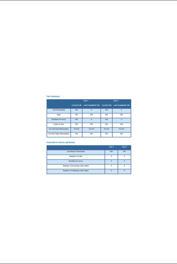
For Line 1 and Line 2, the two available phone lines, the Call Summary section displays the following information:
|
Call Summary - Line 1 and Line 2 |
|
|
|
Current Call/Last Completed Call |
Call Timestamp |
Date and time of the current call |
Type |
May be Incoming or Outgoing |
Duration |
Length of time in seconds of call connection |
Codec in Use |
Audio codec used for decoding the call packet traffic. |
Far-End Host Information |
SIP server IP information: IP address and port number |
Far-End Caller Information |
Caller ID information, if available |
|
Cumulative Since Last Reset |
57

Administrator’s Handbook
Last Reset Timestamp |
Date and time of the last call |
Number of Calls |
Total number of calls for each VoIP line |
Duration |
Time in seconds since the last call |
Number of Incoming Calls Failed |
Number of incoming calls that fail to connect |
Number of Outgoing Calls Failed |
Number of outgoing calls that fail to connect |
The following table shows VoIP line states during various conditions.
VoIP Line |
Hook state |
WAN IP |
Reg-state |
FXS |
Tone |
LED |
|
1/2 |
Voltage |
||||||
|
|
|
|
|
|||
|
|
|
|
|
|
|
|
Disabled |
On/Off-hook |
Up |
Idle |
Off |
N/A |
Off |
|
Enabled |
On-hook |
Up |
Registered |
On |
N/A |
Solid |
|
Enabled |
Off-hook |
Up |
Registered |
On |
Dial tone |
Blink |
|
Enabled |
On/Off hook |
Up |
Failure |
Off |
N/A |
Off |
|
Enabled |
On/Off hook |
Down |
Idle |
Off |
N/A |
Off |
The following table provides the state changes during the boot-up procedure.
VoIP Line |
WAN Status |
Hook State |
Reg-state |
FXS |
Tone |
LED |
|
1/2 |
Voltage |
||||||
|
|
|
|
|
|||
|
|
|
|
|
|
|
|
Disabled |
Down |
Off-hook |
Idle |
On-to-off |
Off |
Off |
|
Enabled |
Down |
On/Off-hook |
Idle |
On |
Congestion |
Off |
|
Enabled |
Up |
Off-hook |
Registered |
On |
Congestion. |
On |
|
|
|
|
|
|
Dial Tone played |
|
|
|
|
|
|
|
after the hook |
|
|
|
|
|
|
|
state is |
|
|
|
|
|
|
|
changed. |
|
58

Firewall
When you click the Firewall tab, the Firewall Status page appears. The Firewall page displays the status of your system firewall elements.
All computer operating systems are vulnerable to attack from outside sources, typically at the operating system or Internet Protocol (IP) layers. Stateful Inspection firewalls intercept and analyze incoming data packets to determine whether they should be admitted to your private LAN, based on multiple criteria, or blocked. Stateful inspection improves security by tracking data packets over a period of time, examining incoming and outgoing packets. Outgoing packets that request specific types of incoming packets are tracked; only those incoming packets constituting a proper response are allowed through the firewall.
Stateful inspection is a security feature that prevents unsolicited inbound access when network address translation (NAT) is disabled. You can configure UDP and TCP “no-activity” periods that will also apply to NAT timeouts if stateful inspection is enabled on the interface. Stateful Inspection parameters are active on a WAN interface only if enabled on your system. Stateful inspection can be enabled on a WAN interface whether NAT is enabled or not.
The Firewall Status page shows whether the each firewall feature is On or Off.
The links at the top of the Firewall page provide access to series of pages that allow you to configure security features of your device.
The links bar on the Firewall page includes the following links. For more information about each link, see the related section in this guide.
Packet Filter (see page 60)
NAT/Gaming (see page 67)
IP Passthrough (see page 72)
Firewall Advanced (see page 75)
59

Administrator’s Handbook
Link: Packet Filter
When you click the Packet Filter link, the Packet Filter page appears.
Security should be a high priority for anyone administering a network connected to the Internet. Using packet filters to control network communications can greatly improve your network’s security. The Packet Filter engine allows creation of a maximum of eight filtersets. Each filterset can have up to eight rules configured.
WARNING:
Before attempting to configure filters and filtersets, please read and understand this entire section thoroughly. The ARRIS NVG599 device incorporating NAT has advanced security features built in. Improperly adding filters and filtersets increases the possibility of loss of communication with the device and the Internet. Never attempt to configure filters unless you are local to the NVG599 device.
Although using filtersets can enhance network security, there are disadvantages:
•Filters are complex. Combining them in filtersets introduces subtle interactions, increasing the likelihood of implementation errors.
•Enabling a large number of filters can have a negative impact on performance. Processing of packets will take longer if they have to go through many checkpoints in addition to NAT.
•Too much reliance on packet filters can cause too little reliance on other security methods. Filtersets are not a substitute for password protection, effective safeguarding of passwords, and general awareness of how your network may be vulnerable.
ARRIS’s packet filters are designed to provide security for the Internet connections made to and from your network. You can customize the NVG599 device’s filtersets for a variety of packet filtering applications. Typically, you use filters to selectively admit or refuse TCP/IP connections from certain remote networks and specific hosts. You will also use filters to screen particular types of connections. This is commonly called firewalling your network.
Before creating filtersets, you should read the next few sections to learn more about how these powerful security tools work.
60
Parts of a Filter
A filter consists of criteria based on packet attributes. A typical filter can match a packet on any one of the following attributes:
The source IP address (where the packet was sent from)
The destination IP address (where the packet is going)
The type of higher-layer Internet protocol the packet is carrying, such as TCP or UDP
Other Filter Attributes
There are three other attributes to each filter:
The filter’s order (i.e., priority) in the filterset
Whether the filter is currently active
Whether the filter is set to forward packets or to block (discard) packets
Design Guidelines
Careful thought must go into designing a new filterset. You should consider the following guidelines:
Be sure the filterset’s overall purpose is clear from the beginning. A vague purpose can lead to a faulty set, and that can actually make your network less secure.
Be sure each individual filter’s purpose is clear.
Determine how filter priority will affect the set’s actions. Test the set (on paper) by determining how the filters would respond to a number of different hypothetical packets.
Consider the combined effect of the filters. If every filter in a set fails to match on a particular packet, the packet is:
•Forwarded if all the filters are configured to discard (not forward)
•Discarded if all the filters are configured to forward
•Discarded if the set contains a combination of forward and discard filters
An Approach to Using Filters
The ultimate goal of network security is to prevent unauthorized access to the network without compromising authorized access. Using filtersets is part of reaching that goal.
Each filterset you design will be based on one of the following approaches:
That which is not expressly prohibited is permitted.
That which is not expressly permitted is prohibited.
We strongly recommend that you take the latter, and safer, approach to all of your filterset designs.
61

Administrator’s Handbook
Working with Packet Filters
To work with filters:
1. Accessing the Packet Filter page by clicking the Packet Filter link.
2.Globally turn filters on or off by clicking the Enable/Disable Packet Filters button.
3.Select the type of packet filter rule by clicking either the Add a ‘Drop’ Rule or Add a ‘Pass’ Rule button.
•If you select a drop rule, the specified packets will be blocked.
•If you select a pass rule, the specified packets will be forwarded.
4.Click the Add Match button to enter the source IP address or destination IP address this filter will match on. As you create new matches, the list items change. There can only be one match from each match type for a given rule. Match types like Source Port, Destination Port, and TCP Flags are only available if other matches (for example, Protocol =TCP) have previously been created.
5.Select a protocol, if necessary, from the pull-down menu: ICMP, TCP, UDP, or None to specify any another IP transport protocol.
If you chose by number, enter the Protocol by number here. If you chose by name, enter the Protocol by name here. Enter the Source Port this filter will match on.
Enter the Destination Port this filter will match on. If you selected ICMP, enter the ICMP Type here.
62

When you are finished configuring the filter, click the Enter Match button.
The filter is automatically saved.
Packet Filter Rules List
Your entries to the packet filter rules list are displayed as a table.
NOTE:
Default Forwarding Filter
If you create one or more filters that have a matching action of forward, then action on a packet matching none of the filters is to block any traffic.
Therefore, if the behavior you want is to force the routing of a certain type of packet and pass all others through the normal routing mechanism, you must configure one filter to match the first type of packet and apply Force Routing. A subsequent filter is required to match and forward all other packets.
Management IP traffic
If the Force Routing filter is applied to source IP addresses, it may inadvertently block communication with the router itself. You can avoid this by preceding the Force Routing filter with a filter that matches the destination IP address of the NVG599 device itself.
63

Administrator’s Handbook
Example:
Assume a configured Custom Service/Hosted Application for an internal web server whose global port range is 8080-8080. Also assume that we want to allow only one external subnet access to this internal server: 207.53.17.0/24. And finally, assume that we want to disallow one IP address on that subnet, 207.53.17.9, from access to that same server (perhaps they were abusing the system in some way). We would need the following rules:
Input Rules
|
Rule |
Action |
Source IP |
Destination IP |
Protocol |
Source |
|
Destination |
|
|
Order |
Port |
|
Port |
|||||
|
|
|
|
|
|
|
|||
1 |
|
Drop |
207.53.17.9 |
- |
TCP |
|
8080 |
||
2 |
|
Pass |
207.53.17.0/24 |
- |
TCP |
|
8080 |
||
3 |
|
Drop |
- |
- |
TCP |
|
8080 |
||
|
|
|
|
|
|
|
|
|
|
|
|
|
|
|
|
|
|
|
|
|
|
|
|
|
|
|
|
|
|
Caution:
If the packet filter or port forwarding rule involves TCP port 80 or 3389; or UDP port 47806, 43962, 69, 123, or 53; or if you attempt to add or change a match such that this occurs and you are running in VDSL/Ethernet mode, the following warning will appear.
64

Example 2
The following example uses the GUI to detail how to create a public subnet.
1. Select Home Network -> Subnets & DHCP from the Web management GUI.
2.Select On from the Public Subnet Enable drop-down menu.
3.Enter all applicable public subnet IP address information and select Save at the bottom of the view.
4.Select Firewall -> Packet Filter to create a packet filter that will allow specific traffic to flow to a public LAN client.
65
Administrator’s Handbook
5.Scroll to the bottom of the screen and select Add a Pass Rule. This rule will allow traffic to flow through the public subnet based on the match criteria that will be set up next.
The new rule will be at the bottom of the Packet Rules list (as shown below).
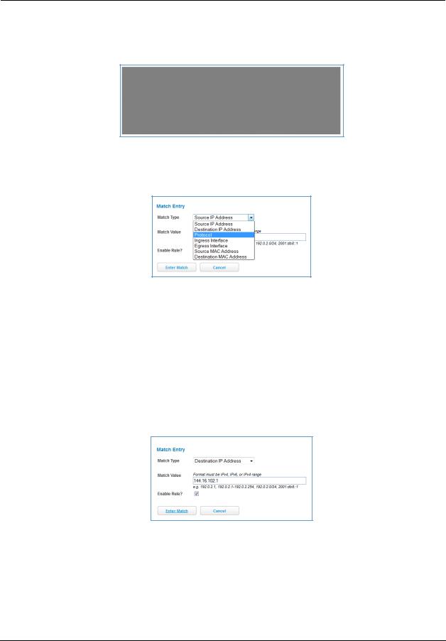
6. Select the Add Match button below the new rule created above. This opens the Match Entry view.
7.For this example, the filter will be made based on a TCP port. Select Protocol from the Match Type dropdown menu. This automatically fills in TCP in the Match Value field. At this point do not enable the rule until all criteria have been entered.
8.Click Enter Match. This will return the GUI to the Packet Rules list.
9.Select Add Match below the rule created earlier.
10.Select Destination Port from the Match Type drop-down menu and enter 21 (this value corresponds to FTP) in the Match Value entry box.
11.Click Enter Match.
12.Select Add Match below the same rule created earlier.
13.Select Destination IP Address from the Match Type drop-down menu and enter the IP address entered in Step 3 of this procedure.
14.Select the Enable Rule check box and click Enter Match. The GUI returns to the Packet Rules list and the rule is active and grayed out. It cannot be edited without first disabling the rule.
66

Link: NAT/Gaming
When you click the NAT/Gaming link, the NAT/Gaming page appears.
The NAT/Gaming feature allows you to host internet applications when NAT (network address translation) is enabled. You can host different games and software on different PCs.
From the Service drop-down menu, you can select any of a large number of predefined games and software. (See “List of Supported Games and Software” on page 70.) In addition to choosing from these predefined services you can also select a user defined custom service. (See “Custom Services” on page 68.)
For each supported game or service, you can view the protocols and port ranges used by the game or service by clicking the Service Details button. For example:
1. Select a hosting device from the Needed by Device drop-down menu.
67
Administrator’s Handbook
2.Once you choose a software service or game, click Add.
Each time you enable a software service or game, your entry will be added to the list of Service names displayed on the NAT/Gaming page.
To remove a game or software from the hosted list, choose the game or software you want to remove and click the Delete button.
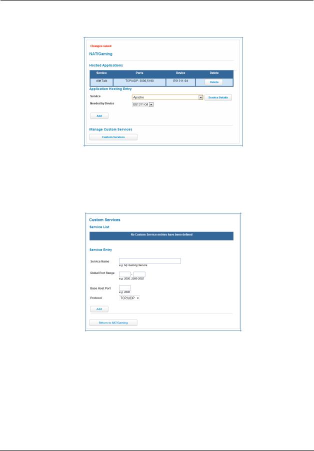
Custom Services
To configure a custom service, click the Custom Services button. The Custom Services page appears.
Enter the following information:
Service Name: A unique identifier for the custom service.
Global Port Range: Range of ports on which incoming traffic will be received.
Base Host Port: The port number at the start of the port range your NVG599 device should use when forwarding traffic of the specified type(s) to the internal IP address.
Protocol: Protocol type of Internet traffic, TCP, UDP, or both.
Click the Add button.
Each time you add a custom service, your entry will be added to the list of service names displayed on the Custom Services page. In addition, once you define a custom service it becomes available in the Service menu on the NAT/Gaming page as one of the services to select.
68
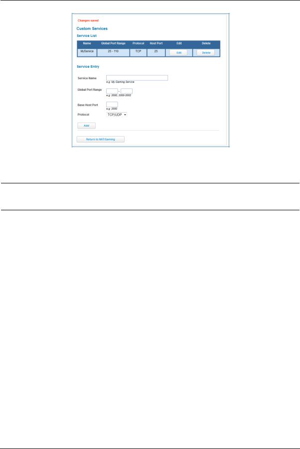
Changes are saved immediately.
To remove this Service, click the Delete button. To edit this Service, click the Edit button.
NOTE:
You cannot edit a custom service if that service is active; it must be inactive before it can be edited.
69

Administrator’s Handbook
List of Supported Games and Software
AIM Talk |
Act of War - Direct Action |
Age of Empires II |
|
|
|
Age of Empires, v.1.0 |
Age of Empires: The Rise of Rome, |
Age of Mythology |
|
v.1.0 |
|
|
|
|
Age of Wonders |
America's Army |
Apache |
|
|
|
Asheron's Call |
Azureus |
Baldur's Gate I and II |
|
|
|
Battlefield 1942 |
Battlefield Communicator |
Battlefield Vietnam |
|
|
|
BitTornado |
BitTorrent |
Black and White |
|
|
|
Blazing Angels Online |
Brothers in Arms - Earned in Blood |
Brothers in Arms Online |
|
|
|
Buddy Phone |
CART Precision Racing, v 1.0 |
Calista IP Phone |
|
|
|
Call of Duty |
Citrix Metaframe/ICA Client |
Close Combat III: The Russian Front, |
|
|
v 1.0 |
|
|
|
Close Combat for Windows 1.0 |
Close Combat: A Bridge Too Far, v |
Combat Flight Sim 2: WWII Pacific |
|
2.0 |
Thr, v 1.0 |
|
|
|
Combat Flight Sim: WWII Europe |
Counter Strike |
DNS Server |
Series, v 1.0 |
|
|
|
|
|
Dark Reign |
Delta Force (Client and Server) |
Delta Force 2 |
|
|
|
Delta Force Black Hawk Down |
Diablo II Server |
Dialpad |
|
|
|
DirecTV STB 1 |
DirecTV STB 2 |
DirecTV STB 3 |
|
|
|
Doom 3 |
Dues Ex |
Dune 2000 |
|
|
|
Empire Earth |
Empire Earth 2 |
F-16, Mig 29 |
|
|
|
F-22, Lightning 3 |
FTP |
Far Cry |
|
|
|
Fighter Ace II |
GNUtella |
Grand Theft Auto 2 Multiplayer |
|
|
|
H.323 compliant (Netmeeting, |
HTTP |
HTTPS |
CUSeeME) |
|
|
|
|
|
Half Life |
Half Life 2 Steam |
Half Life 2 Steam Server |
|
|
|
Half Life Steam |
Half Life Steam Server |
Halo |
|
|
|
Hellbender for Windows, v 1.0 |
Heretic II |
Hexen II |
|
|
|
Hotline Server |
ICQ 2001b |
ICQ Old |
|
|
|
IMAP Client |
IMAP Client v.3 |
IPSec IKE |
|
|
|
Internet Phone |
Jedi Knight II: Jedi Outcast |
Kali |
|
|
|
KazaA |
Lime Wire |
Links LS 2000 |
|
|
|
Lord of the Rings Online |
MSN Game Zone |
MSN Game Zone DX |
|
|
|
MSN Messenger |
Mech Warrior 3 |
MechWarrior 4: Vengeance |
|
|
|
Medal of Honor Allied Assault |
Microsoft Flight Simulator 2000 |
Microsoft Flight Simulator 98 |
|
|
|
Microsoft Golf 1998 Edition, v 1.0 |
Microsoft Golf 1999 Edition |
Microsoft Golf 2001 Edition |
|
|
|
70
Midtown Madness, v 1.0 |
Monster Truck Madness 2, v 2.0 |
Monster Truck Madness, v 1.0 |
|
|
|
Motocross Madness 2, v 2.0 |
Motocross Madness, v 1.0 |
NNTP |
|
|
|
Need for Speed 3, Hot Pursuit |
Need for Speed, Porsche |
Net2Phone |
|
|
|
Operation FlashPoint |
Outlaws |
POP-3 |
|
|
|
PPTP |
PlayStation Network |
Quake 2 |
|
|
|
Quake 3 |
Quake 4 |
Rainbow Six |
|
|
|
RealAudio |
Return to Castle Wolfenstein |
Roger Wilco |
|
|
|
Rogue Spear |
SMTP |
SNMP |
|
|
|
SSH server |
ShoutCast Server |
SlingBox |
|
|
|
Soldier of Fortune |
StarCraft |
StarLancer, v 1.0 |
|
|
|
Starfleet Command |
TFTP |
TeamSpeak |
|
|
|
Telnet |
Tiberian Sun: Command and Con- |
Timbuktu |
|
quer |
|
|
|
|
Total Annihilation |
Ultima Online |
Unreal Tournament Server |
|
|
|
Urban Assault, v 1.0 |
VNC, Virtual Network Computing |
Warlords Battlecry |
|
|
|
Warrock |
Westwood Online, Command and |
Win2000 Terminal Server |
|
Conquer |
|
|
|
|
Wolfenstein Enemy Territory |
World of Warcraft |
X-Lite |
|
|
|
XBox 360 Media Center |
XBox Live 360 |
Yahoo Messenger Chat |
|
|
|
Yahoo Messenger Phone |
ZNES |
eDonkey |
|
|
|
eMule |
eMule Plus |
iTunes |
|
|
|
mIRC Auth-IdentD |
mIRC Chat |
mIRC DCC - IRC DCC |
|
|
|
pcAnywhere (incoming) |
|
|
|
|
|
71
Administrator’s Handbook
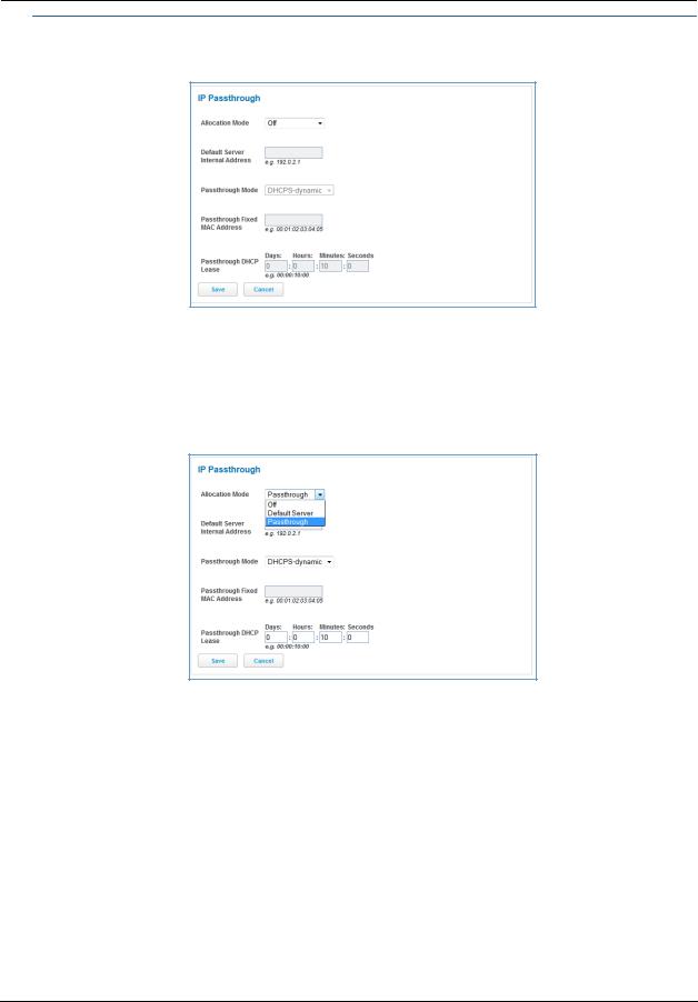
Link: IP Passthrough
When you click the IP Passthrough link, the IP Passthrough page appears.
IP Passthrough
The IP Passthrough feature allows a single PC on the LAN to have the ARRIS Gateway’s public address assigned to it. It also provides PAT (port address translation) (or NAPT – network address and port translation) via the same public IP address for all other hosts on the private LAN subnet.
Using IP Passthrough, the public WAN IP is used to provide IP address translation for private LAN computers. The public WAN IP is assigned and reused on a LAN computer.
72
DHCP address serving can automatically serve the WAN IP address to a LAN computer.
When DHCP is used for addressing the designated passthrough PC, the acquired or configured WAN address is passed to DHCP, which will dynamically configure a single-servable-address subnet, and reserve the address for the configured PC’s MAC address. This dynamic subnet configuration is based on the local and remote WAN address and subnet mask.
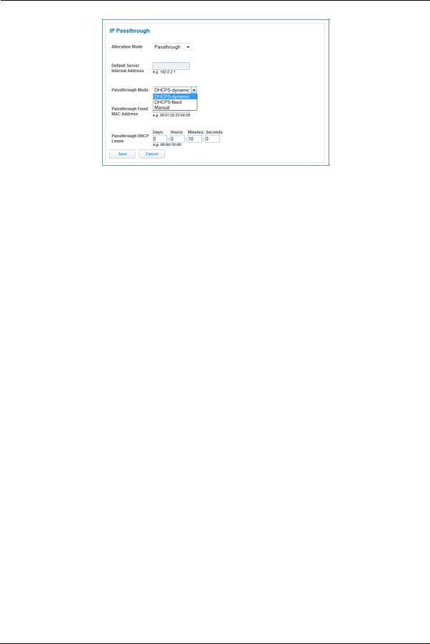
The two DHCP modes assign the needed WAN IP information to the client automatically.
•You can select the MAC address of the PC you want to be the IP Passthrough client with fixed mode, or,
•with “first-come-first-served” – dynamic – the first client to renew its address will be assigned the WAN IP.
Manual mode is like statically configuring your PC. With Manual mode, you configure the TCP/IP Properties of the LAN client PC you want to be the IP Passthrough client. You then manually enter the WAN IP address, gateway address, and so on that matches the WAN IP address information of your ARRIS device. This mode works the same as the DHCP modes. Unsolicited WAN traffic will get passed to this client. The client is still able to access the ARRIS NVG599 device and other LAN clients on the 192.168.1.x network, etc.
The Passthrough DHCP Lease – By default, the passthrough host's DHCP leases will be shortened to two minutes. This allows for timely updates of the host's IP address, which will be a private IP address before the WAN connection is established. After the WAN connection is established and has an address, the passthrough host can renew its DHCP address binding to acquire the WAN IP address. You may alter this setting.
Click Save. Changes take effect upon restart.
A Restriction
Because both the NVG599 device and the passthrough host will use the same IP address, new sessions that conflict with existing sessions will be rejected by the NVG599. For example, suppose you are a teleworker using an IPSec tunnel from the router and from the passthrough host. Both tunnels go to the same remote endpoint, such as the VPN access concentrator at your employer’s office. In this case, the first one to start the IPSec traffic will be allowed; the second one – because, from the WAN, it is indistinguishable – will fail.
73
Administrator’s Handbook
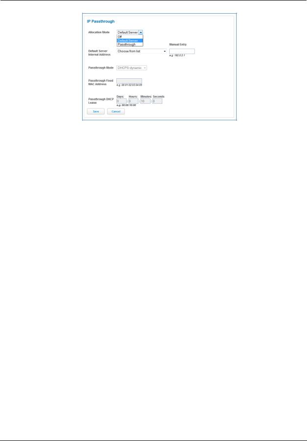
NAT Default Server
The NAT default server feature allows you to:
Direct your NVG599 device to forward all externally initiated IP traffic (TCP and UDP protocols only) to a default host on the LAN, specified by your entry in the Internal Address field.
Enable the default server for certain situations:
–Where you cannot anticipate what port number or packet protocol an in-bound application might use. For example, some network games select arbitrary port numbers when a connection is opened.
–When you want all unsolicited traffic to go to a specific LAN host.
This feature allows you to direct unsolicited or non-specific traffic to a designated LAN station. With NAT on in the device, these packets normally would be discarded. For instance, this feature could be used for application traffic where you do not know in advance the port or protocol that will be used. Some game applications fit this profile.
Click Save. Changes take effect immediately.
74
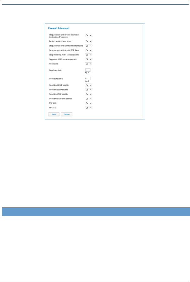
Link: Firewall Advanced
When you click the Firewall Advanced link the Firewall Advanced screen appears.
All computer operating systems are vulnerable to attack from outside sources, typically at the operating system or Internet Protocol (IP) layers. Stateful inspection firewalls intercept and analyze incoming data packets to determine whether they should be admitted to your private LAN, based on multiple criteria, or blocked. Stateful inspection improves security by tracking data packets over a period of time, examining incoming and outgoing packets. Outgoing packets that request specific types of incoming packets are tracked; only those incoming packets constituting a proper response are allowed through the firewall.
Stateful inspection is a security feature that prevents unsolicited inbound access when NAT is disabled. You can configure UDP and TCP “no-activity” periods that will also apply to NAT timeouts if stateful inspection is enabled on the interface. Stateful Inspection parameters are active on a WAN interface only if enabled on your NVG599 device. Stateful inspection can be enabled on a WAN interface whether NAT is enabled or not.
DoS Protection – Denial-of-service (DoS) attacks are common on the Internet, and can render an individual PC or a whole network practically unusable by consuming all its resources. Your NVG599 includes default settings to block the most common types of DoS attacks. For special requirements or circumstances, a variety of additional blocking characteristics are offered. See the following table.
Menu item Function
Drop packets with invalid source or destiWhether packets with invalid source or destination IP address(es) are to be
nation IP address |
dropped |
Protect against port scan |
Whether to detect and drop port scans. |
Drop packets with unknown ether types |
Whether packets with unknown ether types are to be dropped |
Drop packets with invalid TCP flags |
Whether packets with invalid TCP flag settings (NULL, FIN, Xmas, etc.) |
|
should be dropped |
Drop incoming ICMP Echo requests Flood Limit
Whether all ICMP echo requests are to be dropped; On or Off.
Whether packet flooding should be detected and offending packets be dropped; On or Off.
75

Administrator’s Handbook
Menu item |
Function |
|
|
Flood rate limit |
Specifies the number limit of packets per second before dropping the |
|
remainder. |
Flood burst limit |
Specifies the number limit of packets in a single burst before dropping the |
|
remainder. |
Flood limit ICMP enable |
Whether ICMP traffic packet flooding should be detected and offending |
|
packets be dropped; On or Off. |
Flood limit UDP enable |
Whether UDP traffic packet flooding should be detected and offending |
|
packets be dropped; On or Off. |
Flood limit UDP Pass multicast |
Allows exclusion of UDP multicast traffic. On by default. |
Flood limit TCP enable |
Allows exclusion of TCP traffic. Off by default. |
Flood limit TCP SYN-cookie |
Allows TCP SYN cookies flooding to be excluded. |
Neighbor Discovery Attack protection |
Prevents downstream traffic from an upstream device that sends excessive |
|
traffic but receives no replies; On or Off. |
ESP Header Forwarding |
Allows the use of Encapsulating Security Payload (ESP) data payload encryp- |
|
tion for IP Secure (IPsec) from qualifying endpoints; On or Off. |
Authentication Header Forwarding |
Accept and forward IPSec packets with Authencation Headers, which may |
|
be used by some IPSec implementations to validate packet sources ; On or |
|
Off. |
Reflexive ACL |
When IPv6 is enabled, Reflexive Access Control Lists can deny inbound IPv6 |
|
traffic unless this traffic results from returning outgoing packets (except as |
|
configured through firewall rules). |
If you make any changes here, click the Save button.
76

Diagnostics
When you click the Diagnostics tab, the Troubleshoot page appears.
This automated multi-layer test examines the functions of the router from the physical connections to the data traffic being sent by users through the router.
You can run all the tests in order by clicking the Run Full Diagnostics button.
The device will automatically test a number of components to determine any problems. You can see detailed results of the tests by clicking the Details buttons for each item. The details presented depend on the configuration of your router and your network type.
77

Administrator’s Handbook
Here is an example of the Ethernet Details screen.
Test Internet Access
Internet access tests send a ping from the modem to either the LAN or WAN to verify connectivity. A ping could be either an IP address (163.176.4.32) or domain name (www.arris.com). You enter a Web address URL or an IP address in the respective field.
Click the Ping, Trace, or NSLookup button.
Results will be displayed in the Progress Window as they are generated.
Ping - tests the reachability of a particular network destination by sending an ICMP echo request and waiting for a reply.
Traceroute - displays the path to a destination by showing the number of hops and the router addresses of these hops.
NSLookup - converts a domain name to its IP address and vice versa.
To use the ping capability, type a destination address (domain name or IP address) in the text box and click the Ping, Trace, or Lookup button. The results are displayed in the Progress Window.
This sequence of tests takes approximately one minute to generate results. Be sure to wait for the test to run to completion.
78

Each test generates one of the following result codes:
|
|
Result |
|
Meaning |
|
|
|
|
|
|
|
|
|
* PASS: |
The test was successful. |
|
|
|
|
* FAIL: |
The test was unsuccessful. |
|
|
|
|
* SKIPPED: |
The test was skipped because a test on which it depended failed. |
||
|
|
* PENDING: |
The test timed out without producing a result. Try running the test again. |
||
|
|
* WARNING: |
The test was unsuccessful. The service provider equipment your modem connects to may not |
||
|
|
|
support this test. |
|
|
Below are some specific tests: |
|
|
|||
|
|
|
|
|
|
|
|
|
Action |
If Ping Fails, Possible Causes Are: |
|
|
|
|
|
|
|
|
|
|
From the Check Connection Page: |
||
|
|
Ping the Internet default gateway IP address |
DSL is down, DSL settings are incorrect; gateway’s IP |
||
|
|
|
|
address or subnet mask are wrong; gateway router is |
|
|
|
|
|
down. |
|
|
|
Ping an Internet site by IP address |
Site is down. |
||
|
|
Ping an Internet site by name |
Servers are down; site is down. |
||
|
|
|
|
From a LAN PC: |
|
|
|
Ping the modem’s LAN IP address |
IP address and subnet mask of PC are not on the same |
||
|
|
|
|
scheme as the modem; cabling or other connectivity |
|
|
|
|
|
issue. |
|
|
|
Ping an Internet site by IP address |
PC's subnet mask may be incorrect, site is down. |
||
|
|
Ping an Internet site by name |
DNS is not properly configured on the PC, site is down. |
||
79

Administrator’s Handbook
Link: Logs
When you click Logs, the Logs page appears.
The current status of the device is displayed for all logs: System, Firewall, or VoIP. Choose the log you want to display from the drop-down menu.
You can clear all log entries by clicking the Clear Log button.
You can save logs to a text (.TXT) file by clicking the Save to File button. This will download the file to your browser’s default download location on your hard drive. The file can be opened with your favorite text editor.
NOTE:
Some browsers, such as Internet Explorer for Windows XP, require that you specify the ARRIS device’s URL as a “Trusted site” in “Internet Options: Security.” This is necessary to allow the download of the log text file to the PC.
80
 Loading...