


TM508
Table of contents
 Loading...
About this document
This guide describes the installation and testing procedures for the Touchstone
Multi-Line Telephony Modem models (TM508 and TM512).
1 Planning the Installation
Use this chapter to plan the Telephony Modem installation.
2 Installing the Telephony Modem
Use this chapter to install the Telephony Modem.
3Troubleshooting Information
This chapter describes troubleshooting features.
2006-2007 ARRIS
A
ll rights reserved
A
ll information contained in this document is subject to change without notice. ARRIS reserves the right to make
changes to equipment design or program components, as progress in engineering, manufacturing methods, or other
circumstances may warrant.
A
RRIS, ARRIS Interactive, and Touchstone are trademarks of ARRIS Group. All other trademarks are the property of
their respective holders.
Release 5.0 Standard 1.2
March 2007
Touchstone®
TM508/TM512 Installation Guide
Release 5 Standard 1.2
March 2007

ii
Touchstone Telephony Release 5 Standard 1.2 Mar 2007

TM508/TM512 Installation Guide Release 5 Standard 1.2 Mar 2007
iii
Publication history
March 2007
Release 5 Standard 1.2 version of this document.
February 2007
Release 5 Standard 1.1 version of this document.
April 2006
Release 5 Standard 1.0 version of this document.

iv
Touchstone Telephony Release 5 Standard 1.2 Mar 2007

TM508/TM512 Installation Guide Release 5 Standard 1.2 Mar 2007
v
Contents
About this Document vii
Safety Requirements vii
Radio Frequency Emissions and Immunity viii
Product Safety ix
CE Compliance ix
Planning the Installation 1
Environmental Requirements 1
Site Location 1
Power Requirements 2
AC Powering 2
DC Powering 2
Telephony Requirements 4
Network Requirements 4
Telephony Modem Accessories 5
Punch-Block Kit 5
Battery Backup Power Supply 6
Installing the Telephony Modem 7
Cable and Connector Pinouts 8
Telephone Connector Pinouts 8
Telemetry Block Pinouts 8
Procedure: Inspecting and Unpacking the Telephony Modem 10
Action 10
Procedure: Rack-Mounting the Chassis 12
Action 12
Procedure: Wall-Mounting the Chassis 13
Using the Mounting Holes 14
Using the Rack-Mounting Brackets 14
Procedure: Installing the Punch-Block Kit 15
Mounting the Punch-Down Block 16
Connecting Subscriber Wiring 17
Procedure: Connecting Cables 18
Action 19
Procedure: Installing the Battery Backup Power Supply 21
Mounting the Power Supply 22

vi
Touchstone Telephony Release 5 Standard 1.2 Mar 2007
Connecting the Cables 23
Troubleshooting Information 27
Troubleshooting Interfaces 27
Front Panel LEDs 27
Telemetry Block 29
Serial Port 29
TM508/TM512 Installation Guide Release 5 Standard 1.2 Mar 2007
About this Document
This guide describes the installation and testing procedures for the
Touchstone Multi-Line Telephony Modem models:
• TM508A: North American DOCSIS, 100-240V AC/
48V DC Power; 8 telephony lines
• TM512A: North American DOCSIS, 100-240V AC/
48V DC Power; 12 telephony lines
Safety Requirements
ARRIS Telephony Modems comply with the applicable requirements
for performance, construction, labeling, and information when used as
outlined below:
CAUTION
Risk of damage
Make sure that the existing wires providing telephone service are phys-
ically disconnected from the incumbent service provider’s network
interface device. This is a physical break in the connection, not just a
discontinuation of service. Failure to do so will result in damage to the
Telephony Modem.
Connect only DC or AC power, not both, to the TM512. Connecting
both supplies may cause a reset upon loss of AC power.
Do not locate the equipment within 6 feet (1.9m) of a flame or ignition
source (e.g. heat registers, space heaters, fireplaces, etc.), to avoid dam-
age or injury from battery explosion.
Do not use product near water (i.e. wet basement, bathtub, sink or near
a swimming pool, etc.), to avoid risk of electrocution.
Avoid using and/or connecting the equipment during an electrical
storm, to avoid risk of electrocution.

viii
Touchstone Telephony Release 5 Standard 1.2 Mar 2007
Do not locate the equipment within 6 feet (1.9 m) of a flame or ignition
source (i.e. heat registers, space heaters, fireplaces, etc.).
Use only the power cord included with the equipment.
Equipment should be installed near the power outlet and should be eas-
ily accessible.
The shield of the coaxial cable must be connected to earth (grounded)
at the entrance to the building in accordance with applicable national
electrical installation codes. In the U.S., this is required by NFPA 70
(National Electrical Code) Article 820. In the European Union and
cerain other countries, CATV installation equipotential bonding
requirements are specified in IEC 60728-11, Cable networks for televi-
sion signals, sound signals and interactive services, Part 11: Safety.
This equipment is intended to be installed in accordance with the
requirements of IEC 60728-11 for safe operation.
If the equipment is to be installed in an area serviced by an IT power
line network, as is found in many areas of Norway, special attention
should be given that the installation is in accordance with IEC 60728-
11, in particular Annex B and Figure B.4.
In areas of high surge events or poor grounding situations and areas
prone to lightning strikes, additional surge protection may be required
(i.e. PF11VNT3 from American Power Conversion) on the AC, RF,
Ethernet and Phone lines.
When the Telephony Modem is connected to a local computer through
an Ethernet cable, the computer must be properly grounded to the
building/residence AC ground network. All plug in cards within the
computer must be properly installed and grounded to the computer
frame per the manufacturer’s specifications.
Radio Frequency
Emissions and
Immunity
FCC Declaration of Conformity
This equipment has been tested and found to comply with the limits for
a Class B digital device, pursuant to part 15 of the FCC Rules. These
limits are designed to provide reasonable protection against harmful
interference in a residential installation. Operation is subject to the fol-
lowing two conditions: (1) this device may not cause harmful interfer-
ence, and (2) this device may accept any interference that may cause
undesired operations.
This equipment generates, uses and can radiate radio frequency energy
and, if not installed and used in accordance with the instructions, may
cause harmful interference to radio communications. However, there is
no guarantee that interference will not occur in a particular installation.
If this equipment does cause harmful interference to radio or television

ix
TM508/TM512 Installation Guide Release 5 Standard 1.2 Mar 2007
reception, which can be determined by turning the equipment off and
on, the user is encouraged to try to correct the interference by one or
more of the following measures:
Reorient or relocate the receiving antenna.
• Increase the separation between the equipment and the receiver.
• Connect the equipment into an outlet on a circuit different from
that to which the receiver is connected.
• Consult the dealer or an experienced radio/TV technician for
help.
The FCC advises that any unauthorized changes or modifications may
void the user’s authority to operate this equipment. For more informa-
tion on FCC conformity, please contact: ARRIS International, Inc.,
3871 Lakefield Drive, Suite 300, Suwanee, GA 30024.
This product was FCC certified under test conditions that included the
use of the supplied cables between system components. To ensure com-
pliance with FCC regulation, the user must use these cables and install
them properly.
Product Safety UL listed per UL60950-1.
CE Compliance
This product complies with the provisions of the Electromagnetic
Compatibility (EMC) Directive (89/336/EEC), the Amending Directive
(92/31/EEC), the Low Voltage Directive (73/23/EEC), and the CE
Marking Directive (93/68/EEC). As such, this product bears the CE
marking in accordance with the above applicable Directive(s).
A copy of the Declaration of Conformity may be obtained by contact-
ing: ARRIS International, Inc., 3871 Lakefield Drive, Suite 300,
Suwanee, GA 30024.
As indicated by the symbol below, disposal of this product is governed
by Directive 2002/96/EC of the European Parliament and of the Coun-
cil on waste electrical and electronic equipment (WEEE). WEEE could
potentially prove harmful to the environment; as such, upon disposal of
the Telephony Modem the Directive requires that this product must not

x
Touchstone Telephony Release 5 Standard 1.2 Mar 2007
be disposed as unsorted municipal waste, but rather collected sepa-
rately and disposed of in accordance with local WEEE ordinances.

TM508/TM512 Installation Guide Release 5 Standard 1.2 Mar 2007
1
1 Planning the
Installation
Use this chapter to plan the Telephony Modem installation.
Environmental Requirements
Installation of the equipment in a rack should not restrict airflow. In
particular, provide adequate side clearance.
Mount the Telephony Modem properly to prevent uneven mechanical
loading on the chassis. Improper mounting can cause premature failure
and potentially hazardous conditions.
When installed in a closed or multi-unit rack assembly, the operating
temperature inside the rack environment may be higher than ambient
temperature. Install the Telephony Modem in an environment where
the ambient temperatures remains below 50° Celsius.
Site Location
Note: Install the Telephony Modem in a restricted access location.
The Telephony Modem is designed to be installed in a wiring closet
rack. The wiring closet must provide access to power, telephony, and
network facilities as described in this chapter.
The Telephony Modem can be wall-mounted using the rack-mounting
brackets (recommended) or the cutouts on the bottom of the Telephony
Modem. ARRIS recommends wall-mounting to a plywood surface.
2
Touchstone Telephony Release 5 Standard 1.2 Mar 2007
Power Requirements
The Telephony Modem can use either 120V AC power or 48V DC
power. Maximum power consumption is 60 watts.
CAUTION
Risk of equipment damage
Connect only DC or AC power, not both, to the TM512. Connecting
both supplies may cause a reset upon loss of AC power.
Each type of power supply has a separate power connector mounted on
the rear panel of the Telephony Modem. The power connectors are typ-
ically plugged into the AC power or DC power distribution unit of the
rack or cabinet using the power cords supplied with the Telephony
Modem.
Note: Make sure that the power circuits have sufficient capacity to
power the Telephony Modem before connecting power.
AC Powering The Telephony Modem requires up to 85 VA, 47 to 63 Hz AC power.
The socket-outlet must be properly earthed.
DC Powering For DC powering, ARRIS recommends the use of a Local Battery
Backup Supply, part number 718115K. The DC input voltage range is
40 V DC to 60 V DC; the nominal voltage is 48 V DC. The DC power
supply requires up to 60 watts of DC power from a SELV rated source.
If you intend to power the Telephony Modem from a common 48V DC
supply, contact ARRIS for recommendations. The following table
shows the DC power connections.
Signal To AWG Color
DC RTN - 16 Black
48V Feed 1 + 16 Red
3
TM508/TM512 Installation Guide Release 5 Standard 1.2 Mar 2007
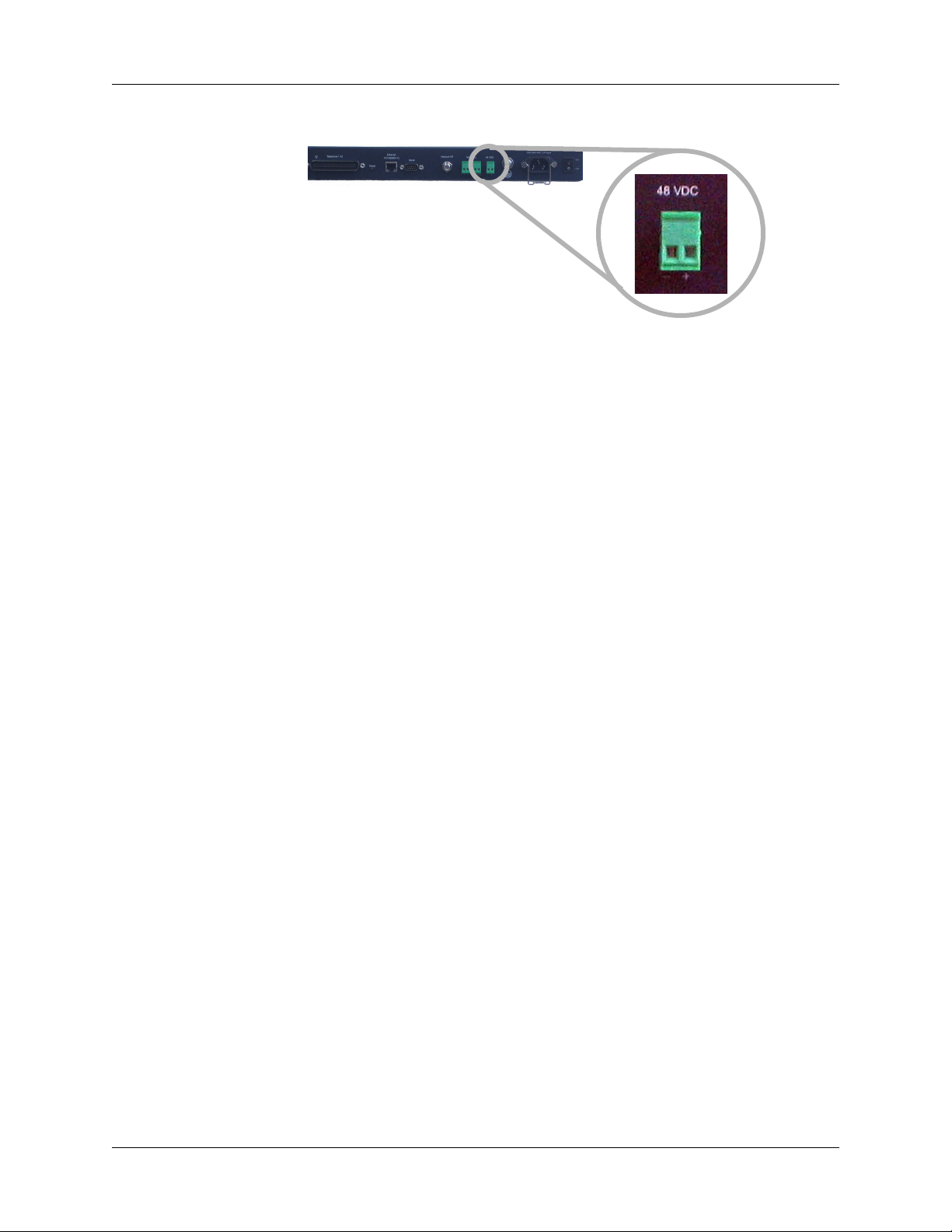
The following diagram shows the location of the DC connector.
Loading...