


ARRIS
Wireless TV Receiver
Product Manual
VIP2500
For use with your AT&T U-verse TV Service

CAUTION
RISK OF ELECTRIC SHOCK
DO NOT OPEN
TO REDUCE RISK OF ELECTRIC SHOCK, DO NOT REMOVE COVER (OR BACK). NO USER-SERVICEABLE PARTS INSIDE.
REFER SERVICING TO QUALIFIED SERVICE PERSONNEL.
Graphical symbols and supplemental warning markings are located on the back and bottom of the terminal.
WARNING
TO REDUCE THE RISK OF FIRE OR SHOCK, DO NOT EXPOSE THIS APPLIANCE TO RAIN OR MOISTURE.
The lightning flash with arrowhead symbol within an equilateral triangle is intended to alert the user to the presence of uninsulated dangerous voltage within the product’s enclosure that may be of sufficient magnitude to constitute a risk of electric shock to persons.
The exclamation point within an equilateral triangle is intended to alert the user to the presence of important operating and maintenance (servicing) instructions in the literature accompanying the appliance.
Product identification and supply rating are provided on the label found on the bottom of the unit.
IMPORTANT SAFETY INSTRUCTIONS
•Read these instructions.
•Keep these instructions.
•Heed all warnings.
•Follow all instructions.
•Do not use this apparatus near water.
•Clean only with a dry cloth.
•Do not block any ventilation openings. Install according to the manufacturer’s instructions.
•Do not install near any heat sources, such as radiators, heat registers, stoves, or other apparatus (including amplifiers) that produce heat.
•Protect the power cord from being walked on or pinched, particularly at plugs, convenience receptacles, and the point where they exit from the apparatus.
•Only use attachments/accessories specified by the manufacturer.
•Unplug this apparatus during lightning storms or when unused for long periods of time.
•Refer all servicing to qualified service personnel. Servicing is required when the apparatus has been damaged in any way, such as the power supply cord or plug is damaged, liquid has been spilled or objects have fallen into the apparatus, the apparatus has been exposed to rain or moisture, does not operate normally, or has been dropped.
ii |
U-verse VIP2500 Wireless Receiver Product Manual |
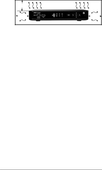
At least 2 inches
V E N T I L A T E
2 inches |
2 inches |
Follow these important safety guidelines when positioning and connecting your wireless receiver:
•Do not block the slots and openings
•Do not place anything on top of the wireless receiver
•Do not position the wireless receiver in a confined space, such as an enclosed cabinet, that does not provide adequate ventilation.
•Do not position the wireless receiver near any external heat source that could raise the temperature around the unit. Do not place the wireless receiver on top of another heat producing electronic device.
•Allow for adequate ventilation around the wireless receiver to maintain normal operating temperature. Do not place it in a sealed enclosure without providing for adequate airflow.
•Do not plug the AC power adapter into a switched power outlet.
•Always transport the receiver in its original factory carton, or in an equally well-padded container.
•Whether installed or being transported, do not expose the receiver to temperature extremes. The temperature range for operation is from 0° to +40°C. The non-operating (transport or storage) temperature range is from -40° to +60°C.
•If the wireless receiver is used outdoors (patio, balcony, etc.), it should be protected from moisture, temperature extremes, and from prolonged exposure to direct sunlight, any of which could cause damage. Note also that adequate ventilation must be maintained, even if the wireless receiver is operated outdoors.
This manual includes the manufacturer’s recommended safeguards and all the information needed to connect your receiver to both your in-home IP network and your entertainment system. The safety and installation information was developed and provided primarily by the receiver manufacturer, ARRIS Enterprises, Inc.
U-verse VIP2500 Wireless Receiver Product Manual |
iii |

Contents
Introduction . . . . . . . . . . . . . . . . . . . . . . . . . . . . . . |
1 |
Overview . . . . . . . . . . . . . . . . . . . . . . . . . . . . . . . |
2 |
Front Panel . . . . . . . . . . . . . . . . . . . . . . . . . . . . . . |
. 2 |
VIP2500 Rear Panel . . . . . . . . . . . . . . . . . . . . . . . . . . . |
3 |
Wireless Connection . . . . . . . . . . . . . . . . . . . . . . . . . . . 4 |
|
Wireless Access Point . . . . . . . . . . . . . . . . . . . . . . . . . 4 |
|
Register the TV Receiver with the Access Point . . . . . . . . . . . . . . |
. 4 |
Connecting Your TV Receiver . . . . . . . . . . . . . . . . . . . . . . . |
. 5 |
Connection Options . . . . . . . . . . . . . . . . . . . . . . . . . . 5 |
|
Common Cabling Examples . . . . . . . . . . . . . . . . . . . . . . . 6 |
|
Connecting to an HDTV – Video Only . . . . . . . . . . . . . . . . . . . . |
7 |
Connecting to an HDTV – Audio Only . . . . . . . . . . . . . . . . . . . . |
8 |
Connecting Audio to a Home Theater Receiver . . . . . . . . . . . . . . . . |
. 9 |
Connecting to a Stereo TV . . . . . . . . . . . . . . . . . . . . . . . . |
10 |
Troubleshooting . . . . . . . . . . . . . . . . . . . . . . . . . . . . |
11 |
iv |
U-verse VIP2500 Wireless Receiver Product Manual |

Introduction
Congratulations on receiving your U-verse VIP2500 Wireless Receiver.
The VIP2500 Series provides these extraordinary home entertainment features:
•With U-verse Wireless Receiver, you have the freedom to move your TV where you want -- anywhere in your home
•Pause your recorded show in one room and pick it up in another with Total Home DVR
•High Definition TV (HDTV), which provides up to twice the color resolution and up to six times the sharpness of standard TV when connected to an HD-capable TV
•Do more than just watch TV; explore, entertain and interact with U-verse Apps
•Enjoy easy access to the hottest Hollywood hits in HD quality with U-verse Movies
•Rich picture quality, with 100% digital picture and sound
This installation manual introduces the basic features, outlines important safeguards, and provides options for integrating your wireless receiver into your entertainment system. Take a few moments to read through this manual. Its configuration diagrams and troubleshooting section will help you make the most of your home entertainment experience.
Included in the carton:
•U-verse VIP2500 Wireless Receiver
•Power adapter
For more information about your AT&T U-verse TV service and its capabilities, refer to the other documentation from your service provider.
Dimensions: 9.25” (235 mm) Wide, 1.77” (45 mm) High, 6.26” (159 mm) Long
Unit Weight: |
1.1 Lbs. (0.5 kg) |
U-verse VIP2500 Wireless Receiver Product Manual |
1 |

Overview
Front Panel
The illustration below and the table following it describe the front-panel features, controls and indicator lights.
1 |
2 |
3 |
4 |
5 |
6 |
7 |
8 |
|
|
|
|
|
|
|
|
|
|
Key |
Item |
Function |
||
|
|
|
|
|
1 |
POWER |
Turns the U-verse Wireless Receiver on or off |
||
|
|
If held for ten (10) seconds or longer, restarts the wireless |
||
|
|
receiver |
||
|
|
Lights green when the wireless receiver is on |
||
|
|
|
|
|
2 |
USB |
USB 2.0 connector |
||
|
|
|
|
|
3 |
SIGNAL |
The five-bar display lights green to indicate signal strength |
||
|
STRENGTH |
from your wireless Access Point device. From one to five |
||
|
|
bars are lit, depending on the strength of the received signal. |
||
|
|
When signal strength is low bars may display as amber |
||
|
|
(weak) or red (unusable). See the Troubleshooting section on |
||
|
|
page 11 for details. |
||
|
|
|
|
|
4 |
LINK |
Lights green when a network connection is established |
||
|
|
|
|
|
5 |
HD |
Lights blue when receiver is set to video resolution of 720p |
||
|
|
or 1080i |
||
|
|
|
|
|
6 |
RECORD |
Lights red when a recording is in progress |
||
|
|
|
|
|
7 |
MENU |
Displays the AT&T U-verse menu on your TV screen |
||
|
|
|
|
|
8 |
Up/Down |
Changes the channel (channel up/channel down) |
||
|
arrow keys |
|
|
|
|
Left/Right |
Use to navigate through on-screen program guide and menu |
||
|
arrow keys |
|
|
|
|
OK |
Use to select programs or accept menu options |
||
|
center key |
|
|
|
|
|
|
|
|
|
|
|
|
|
2 |
U-verse VIP2500 Wireless Receiver Product Manual |

Overview
Rear Panel
The VIP2500 rear panel features are described in the following table.
Key |
Item |
Function |
|
|
|
1 |
NETWORK |
Ethernet 10/100Base-T RJ-45 port |
|
|
|
2 |
Y |
|
3 |
Pb |
RCA component video outputs to an HDTV |
4 |
Pr |
|
|
|
|
5 |
VIDEO OUT |
RCA standard-definition composite video output to a TV, |
|
|
VCR, or other device |
|
|
|
6 |
L R |
Left and right RCA stereo audio (analog) outputs |
7 |
AUDIO OUT |
|
|
|
|
8 |
OPTICAL |
Toslink (S/PDIF) digital audio output |
|
|
|
9 |
HDMI™ |
Connects to a High Definition TV or home theater receiver |
|
|
with an HDMI input (for a DVI input, use an HDMI-to-DVI |
|
|
adapter) |
|
|
|
10 |
POWER |
Connector for the DC power adapter. Use only the adapter |
|
+12 VDC |
specified for VIP2500. |
|
|
|
U-verse VIP2500 Wireless Receiver Product Manual |
3 |

Wireless Connection
As shown in the illustration below, video for the VIP2500 is transmitted wirelessly over the air from a Wireless Access Point. The access point, in turn, is connected to your residential gateway device.
|
802.11n Wireless Link |
|
|
|
|
|
|
|
|
VIP2500 |
|
Residential Gateway |
Wireless Access Point |
Wireless TV Receiver |
|
Wireless Access Point
Your Wireless Access Point is capable of transmitting separate video streams to multiple Wireless TV Receivers as specified by your service provider. The Access point uses Wi-Fi Protected Setup (WPS) protocols to identify, authorize and manage traffic to and from the Wireless TV Receivers.
Register the TV Receiver with the Access Point
Before your Wireless TV Receiver can become operational, it must be paired as an authorized device with the Access Point. Run the WPS procedure as follows:
1.Install the Access Point as described in the accompanying installation document.
2.Connect the cord from the DC Power Adapter to the POWER +12VDC connector on the rear of the Access Point, and plug the adapter into an AC wall socket, and then connect the VIP2500 to your TV set as described starting on page 5.
3.The POWER button on the front of the VIP2500 lights green to indicate power is applied. Ensure power is applied to your TV, as well.
4.Ensure that the Access Point is connected to your home gateway device, and that power is applied to it.
5.When the VIP2500 starts up, it will look for a signal from an Access Point. A prompt will appear on your TV screen asking if you wish to connect.
Wireless Access point
WPS
Button
6.On the front panel of the VIP2500, press OK.
7.Press and hold the WPS button on the front of the Access Point for two seconds, then release to activate the WPS process. The Access Point’s WPS LED will blink orange.
8.An icon appears on the screen, indicating that the connection is in process. When the connection has been established, the screen will display Success.
9.On the front panel of the VIP2500, two or more bars of the Signal Strength Indicator should light green. You have now established a secure wireless connection between the Access Point and the Wireless TV Receiver.
For further information on the Wireless Access Point, refer to the documentation provided.
4 |
U-verse VIP2500 Wireless Receiver Product Manual |
 Loading...