


 Loading...
User Guide
ARRIS SURFboard®
SBM1000 SMART Video Adapter Kit*
*SBM1100
SBM1400
© 2013 ARRIS Enterprises, Inc. All rights reserved.
No part of this publication may be reproduced in any form or by any means or used to make any derivative work (such as translation, transformation, or adaptation) without written permission from ARRIS Enterprises, Inc. (“ARRIS”). ARRIS reserves the right to revise this publication and to make changes in content from time to time without obligation on the part of ARRIS to provide notification of such revision or change.
ARRIS, SURFboard, and the ARRIS logo are trademarks or registered trademarks of ARRIS Enterprises, Inc. All other trademarks are the property of their respective owners.
MOTOROLA and the Stylized M Logo are trademarks or registered trademarks of Motorola Trademark Holdings, LLC, and are used by ARRIS under license. All other product or service names are the property of their respective owners.
ARRIS provides this guide without warranty of any kind, implied or expressed, including, but not limited to, the implied warranties of merchantability and fitness for a particular purpose. ARRIS may make improvements or changes in the product(s) described in this manual at any time.

Safety and Regulatory Information
i
Safety and Regulatory
Information
IMPORTANT SAFETY INSTRUCTIONS
•Read This Before You Begin — When using your equipment, basic safety precautions should always be followed to reduce the risk of fire, electric shock, and injury to persons, including the following:
•Read all of the instructions listed here and/or in the user manual before you operate this device. Give particular attention to all safety precautions. Retain the instructions for future reference.
•This device must be installed and used in strict accordance with manufacturer’s instructions, as described in the user documentation that is included with the device.
•Comply with all warning and caution statements in the instructions. Observe all warning and caution symbols that are affixed to this device.
•To prevent fire or shock hazard, do not expose this device to rain or moisture. The device must not be exposed to dripping or splashing. Do not place objects filled with liquids, such as vases, on the device.
•This device was qualified under test conditions that included the use of the supplied cables between system components. To ensure regulatory and safety compliance, use only the provided power and interface cables and install them properly.
•Different types of cord sets may be used for connections to the main POWER supply circuit. Use only a main line cord that complies with all applicable device safety requirements of the country of use.
•Installation of this device must be in accordance with national wiring codes and conform to local regulations.
•Operate this device only from the type of power source indicated on the device’s marking label. If you are not sure of the type of power supplied to your home, consult your dealer or local power company.
•Do not overload outlets or extension cords, as this can result in a risk of fire or electric shock. Overloaded AC outlets, extension cords, frayed power cords, damaged or cracked wire insulation, and broken plugs are dangerous. They may result in a shock or fire hazard.
•Route power supply cords so that they are not likely to be walked on or pinched by items placed upon or against them. Pay particular attention to cords where they are attached to plugs and convenience receptacles, and examine the point where they exit from the device.
•Place this device in a location that is close enough to an electrical outlet to accommodate the length of the power cord.
•Place the device to allow for easy access when disconnecting the power cord of the device from the AC wall outlet.
•Do not connect the plug into an extension cord, receptacle, or other outlet unless the plug can be fully inserted with no part of the blades exposed.
•Place this device on a stable surface.
•Avoid damaging the device with static by touching the coaxial cable when it is attached to the earth-grounded coaxial cableTV wall outlet.
•Always first touch the coaxial cable connector on the device when disconnecting or reconnecting the Ethernet cable from the device or user’s PC.
•It is recommended that the customer install an AC surge protector in the AC outlet to which this device is connected. This is to avoid damaging the device by local lightning strikes and other electrical surges.
•Postpone installation until there is no risk of thunderstorm or lightning activity in the area.
•Do not use this product near water: for example, near a bathtub, washbowl, kitchen sink or laundry tub, in a wet basement, or near a swimming pool.
SBM1000 SMART Video Adapter Kit • User Guide |
iii |
590631-001-a |
|

Safety and Regulatory Information
•Do not cover the device or block the airflow to the device with any other objects. Keep the device away from excessive heat and humidity and keep the device free from vibration and dust.
•Wipe the device with a clean, dry cloth. Never use cleaning fluid or similar chemicals. Do not spray cleaners directly on the device or use forced air to remove dust.
•For added protection, unplug the device from the wall outlet and disconnect the cables to avoid damage to this device due to lightning and power surges.
•Upon completion of any service or repairs to this device, ask the service technician to perform safety checks to determine that the device is in safe operating condition.
•Do not open the device. Do not perform any servicing other than that contained in the installation and troubleshooting instructions. Refer all servicing to qualified service personnel.
This device should not be used in an environment that exceeds 104º F (40º C).
SAVE THE ABOVE INSTRUCTIONS
Note to CATV System Installer — This reminder is provided to call the CATV system installer’s attention to Article 820.93 and 820.100 of the National Electric Code, which provides guidelines for proper grounding and, in particular, specifies that the Coaxial cable shield shall be connected to the grounding system of the building, as close to the point of cable entry as practical.
FCC STATEMENTS
FCC Interference Statement
This equipment has been tested and found to comply with the limits for a Class B digital device, pursuant to part 15 of the FCC Rules. These limits are designed to provide reasonable protection against harmful interference in a residential environment. This equipment generates, uses, and can radiate radio frequency energy and, if not installed and used in accordance with the instructions, may cause harmful interference to radio communications. However, there is no guarantee that interference will not occur in a particular installation. If this equipment does cause harmful interference to radio or television reception, which can be determined by turning the device off and on, the user is encouraged to try to correct the interference by one or more of the following measures:
•Reorient or relocate the receiving antenna.
•Increase the separation between the device and receiver.
•Connect the equipment into an outlet on a circuit different from that to which the receiver is connected.
•Consult the dealer or an experienced radio/TV technician for help.
This device complies with Part 15 of the FCC Rules. Operation is subject to the following two conditions: (1) This device may not cause harmful interference, and (2) This device must accept any interference received, including interference that may cause undesired operation.
FCC CAUTION: Any changes or modifications not expressly approved by ARRIS for compliance could void the user’s authority to operate the equipment.
FCC Declaration of Conformity
ARRIS Enterprises, Inc., 101 Tournament Drive, Horsham, PA 19044, 1-215-323-1000, declares that the SURFboard® SBM1000 SMART Video Adapter Series complies with 47 CFR Parts 2 and 15 of the FCC rules as a Class B digital device.
Industry Canada (IC) Statement
CAN ICES-3 (B)/NMB-3 (B)
SBM1000 SMART Video Adapter Kit • User Guide |
iv |
590631-001-a |
|

|
Contents |
Safety and Regulatory Information.......................................................................................................... |
iii |
Introduction ................................................................................................................................................. |
1 |
Product Overview ......................................................................................................................................... |
1 |
Standard Features................................................................................................................................... |
1 |
In the Box ...................................................................................................................................................... |
2 |
Contact Information ...................................................................................................................................... |
3 |
Product Overview ....................................................................................................................................... |
4 |
Front Panel .................................................................................................................................................... |
4 |
Rear Panel ..................................................................................................................................................... |
6 |
Installing the MoCA Adapters ................................................................................................................... |
7 |
Pre-installation Guidelines ............................................................................................................................. |
7 |
Getting Started.............................................................................................................................................. |
7 |
Network Service Providers List .............................................................................................................. |
8 |
Home Network Installation Scenarios .................................................................................................... |
8 |
1 Cable Network Installations ..................................................................................................................... |
10 |
1.1 Installing for Cable with Separate Cable Modem & Router ........................................................... |
11 |
1.2 Installing for Cable with an Integrated Cable Modem & Router |
|
(without MoCA Capability).............................................................................................................. |
14 |
1.3 Installing for Cable with Integrated Cable Modem & Router |
|
(with MoCA).................................................................................................................................... |
17 |
2 AT&T Telco Installations........................................................................................................................... |
19 |
2.1 Installing for AT&T U-verse with a Separate Wi-Fi Router ............................................................. |
20 |
2.2 Installing for AT&T U-verse with AT&T Gateway-Integrated |
|
Modem & Router............................................................................................................................ |
22 |
2.3 Installing for AT&T U-verse with an Ethernet-connected |
|
Set-top Box ..................................................................................................................................... |
24 |
3 Verizon FiOS Installation .......................................................................................................................... |
26 |
4 Dish/EchoStar Installation ........................................................................................................................ |
28 |
5 DirecTV Installations................................................................................................................................. |
30 |
5.1 Installing for DirecTV with Single Wire Multi-Switch (SWiM) ........................................................ |
31 |
5.2 Installing for DirecTV (non-SWiM) .................................................................................................. |
33 |
6 Over-the-Air (OTA) Installation ................................................................................................................. |
35 |
Setting Up Access to the Web Admin Interface .................................................................................... |
37 |
Configure a Temporary IP Address ............................................................................................................. |
37 |
Access the SBM1000 Web Admin Interface .............................................................................................. |
41 |
Change My IP Address Back to the Original Configuration ........................................................................ |
42 |
Configuring the MoCA Adapters ............................................................................................................. |
46 |
SBM1000 SMART Video Adapter Kit • User Guide |
v |
590631-001-a |
|

Tables |
|
Prevent Unauthorized Access..................................................................................................................... |
46 |
Manage Your Passwords ............................................................................................................................ |
46 |
Change Your Administrator Security Password ................................................................................... |
47 |
Change the MoCA Network Security Password .................................................................................. |
48 |
Find Current Network Security Password ............................................................................................ |
49 |
Restore Factory Defaults ............................................................................................................................ |
50 |
Change the Adapter IP Configuration ......................................................................................................... |
51 |
Upgrade the Adapter Firmware................................................................................................................... |
52 |
Change the Default MoCA Beacon Power Level........................................................................................ |
53 |
Change the Default MoCA Channel of Operation....................................................................................... |
55 |
Access the SBM1000 MoCA Statistics ...................................................................................................... |
57 |
Troubleshooting Tips................................................................................................................................ |
59 |
Solutions...................................................................................................................................................... |
59 |
Adapter Configuration Screen Definitions ............................................................................................. |
62 |
Settings Screens ......................................................................................................................................... |
62 |
MoCA Setup ......................................................................................................................................... |
62 |
Device Setup ........................................................................................................................................ |
64 |
Status Screens ............................................................................................................................................ |
65 |
Device Status........................................................................................................................................ |
65 |
PHY Rates............................................................................................................................................. |
67 |
Advanced Screens ...................................................................................................................................... |
68 |
Security Setup ...................................................................................................................................... |
68 |
Upgrade ................................................................................................................................................ |
70 |
Warranty Information ............................................................................................................................... |
72 |
|
Tables |
Table 1 – SBM1000 Video Adapter Package Contents................................................................................. |
2 |
Table 2 – SMART Video Adapter Front Panel LEDs...................................................................................... |
5 |
Table 3 – SMART Video Adapter Rear Panel Ports & Connectors................................................................ |
6 |
Table 4 – Troubleshooting Solutions ........................................................................................................... |
59 |
Table 5 – MoCA Setup Screen-Field Descriptions ...................................................................................... |
63 |
Table 6 – Device Setup Screen-Field Descriptions ..................................................................................... |
64 |
Table 7 – Device Status Screen-Field Descriptions..................................................................................... |
66 |
Table 8 – PHY Rates Status Screen-Field Descriptions .............................................................................. |
67 |
Table 9 – Advanced Security Setup Screen-Field Descriptions .................................................................. |
69 |
Table 10 – Advanced Upgrade Screen-Field Descriptions .......................................................................... |
71 |
SBM1000 SMART Video Adapter Kit • User Guide |
vi |
590631-001-a |
|

Figures |
|
|
Figures |
Figure 1 – SBM1100 Single-Port SMART Video Adapter Front View ........................................................... |
4 |
Figure 2 – SBM1400 Four-Port SMART Video Adapter Front View.............................................................. |
4 |
Figure 3 – SBM1100 One-Port SMART Video Adapter Rear View ............................................................... |
6 |
Figure 4 – SBM1400 Four-Port SMART Video Adapter Rear View............................................................... |
6 |
Figure 5 – Installation Scenarios Flowchart................................................................................................... |
9 |
Figure 6 – Cable Network Installations Flowchart....................................................................................... |
10 |
Figure 7 – Cable Installation with Separate Cable Modem & Router ......................................................... |
11 |
Figure 8 – Room 1: SBM1400 Adapter Installation..................................................................................... |
12 |
Figure 9 – Room 2: SBM1100 Adapter Installation with Cable Modem & Router ..................................... |
12 |
Figure 10 – Cable/Telco Installation with Integrated Cable Modem & Router............................................ |
14 |
Figure 11 – Room 1: SBM1400 Adapter Installation................................................................................... |
15 |
Figure 12 – Room 2: SBM1100 Adapter Installation with Gateway ........................................................... |
15 |
Figure 13 – Cable/Telco Installation with Integrated Cable Modem/Router with MoCA............................ |
17 |
Figure 14 – Room 1: SBM1400 Adapter Installation................................................................................... |
18 |
Figure 15 – AT&T Telco Installations Flowchart.......................................................................................... |
19 |
Figure 16 – AT&T U-verse Installation with Separate Wi-Fi Router ............................................................ |
20 |
Figure 17 – Room 1: SBM1400 Adapter Installation................................................................................... |
21 |
Figure 18 – Room 1: AT&T U-verse Installation with Gateway................................................................... |
22 |
Figure 19 – Room 1: SBM1400 Adapter Installation................................................................................... |
23 |
Figure 20 – AT&T U-verse Installation with Ethernet-connected Set-top Box............................................ |
24 |
Figure 21 – Room 1: SBM1400 Adapter Installation................................................................................... |
25 |
Figure 22 – Verizon FiOS Installation .......................................................................................................... |
26 |
Figure 23 – Room 1: SBM1400 Adapter Installation................................................................................... |
27 |
Figure 24 – Dish/EchoStar Installation ........................................................................................................ |
28 |
Figure 25 – Room 1: SBM1400 Adapter Installation................................................................................... |
29 |
Figure 26 – DirecTV Installations Flowchart................................................................................................ |
30 |
Figure 27 – DirecTV Installation with Single Wire Multi-Switch (SWiM) .................................................... |
31 |
Figure 28 – DirecTV Installation (Non-SWiM).............................................................................................. |
33 |
Figure 29 – Room 1: SBM1400 Adapter Installation................................................................................... |
34 |
Figure 30 – Over-the-Air (OTA) Installation ................................................................................................. |
35 |
Figure 31 – Room 1: SBM1400 Adapter Installation................................................................................... |
36 |
Figure 32 – Changing My Admin Security Password.................................................................................. |
47 |
Figure 33 – Changing My Network Security Password .............................................................................. |
48 |
Figure 34 – Finding the Current Network Security Password..................................................................... |
49 |
Figure 35 – Restoring Factory Default Settings .......................................................................................... |
50 |
Figure 36 – Changing the Adapter IP Configuration.................................................................................... |
51 |
Figure 37 – Upgrade Firmware Screen ....................................................................................................... |
52 |
Figure 38 – Change Default MoCA Beacon Power Level Screen............................................................... |
54 |
SBM1000 SMART Video Adapter Kit • User Guide |
vii |
590631-001-a |
|

Figures |
|
|
Figure 39 – Change Default MoCA Channel of Operation Screen.............................................................. |
55 |
|
Figure 40 – Select Single Channel of Operation Screen ............................................................................. |
56 |
|
Figure 41 – MoCA Adapter Device Status Screen...................................................................................... |
57 |
|
Figure 42 – MoCA Adapter(s) PHY Rates Screen ....................................................................................... |
58 |
|
Figure 43 – MoCA Setup Screen ................................................................................................................ |
62 |
|
Figure 44 – Device Setup Screen................................................................................................................ |
64 |
|
Figure 45 – Device Status Screen............................................................................................................... |
65 |
|
Figure 46 |
– PHY Rates Status Screen......................................................................................................... |
67 |
Figure 47 |
– Advanced Security Setup Screen............................................................................................. |
68 |
Figure 48 |
– Advanced Upgrade Screen....................................................................................................... |
70 |
SBM1000 SMART Video Adapter Kit • User Guide |
viii |
590631-001-a |
|

Introduction
1 |
Introduction |
|
Product Overview
Your new ARRIS SURFboard® SBM1000 SMART Video Adapters are high-performance network adapters which use Multimedia over Coax (MoCA) technology to enable connectivity of Ethernet-enabled devices in your home through the existing coaxial cable network. MoCA allows you to share high-definition IP-based multi-media content to multiple Ethernet-enabled devices such as home computers, Smart TVs, set-top boxes, gaming devices, and multi-room DVRs in every room of the house serviced by the coaxial cable network.
There are two SMART video adapters included in your adapter kit. The SBM1100, a single Ethernet port MoCA adapter, enables you to connect an existing cable modem/router/network device to your coaxial cable network. The SBM1400, a four Ethernet port MoCA adapter, enables you to connect up to four network devices to your coaxial cable network.
The SBM1000 adapters will coexist with Telco, Cable, and Satellite TV services. Set up is easy. If you already have available coaxial cable outlets, you will not have to install any new wires or cables.
This guide provides instructions for installing and setting up the SBM1000 SMART Video Adapters on your home network to share audio-visual media content in multiple rooms in your home.
Standard Features
•Built-in MoCA 1.1 technology that works with your existing wireless and MoCA networks
•Supports Cable, Verizon FiOS®, U-Verse®, and DirecTV® networks
•Supports 10/100 Mbps Ethernet connections
•Easy to install – requires no new electrical or cable wiring
•Uses existing home coaxial cabling
•Plugs into the existing cable outlet in your home
•Automatically detects and connects to the existing coaxial cable network
•Delivers high-speed Internet access to HDTVs, set-top boxes, gaming consoles, and other Ethernet-enabled electronic devices in your home
•Front panel status LEDs
•Password protection for secure access control
SBM1000 SMART Video Adapter Kit • User Guide |
1 |
590631-001-a |
|
Introduction
In the Box
Before getting started, check that the following items are included in the SBM1000 box. If any items are missing, please contact ARRIS Technical Support Center at: 1-877-466-8646.
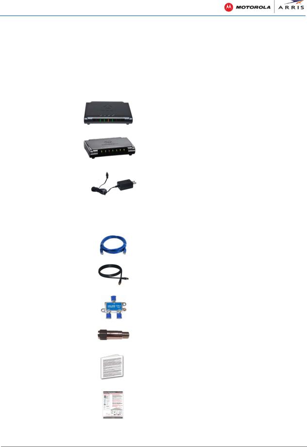
Table 1 – SBM1000 Video Adapter Package Contents
ITEM |
|
|
|
DESCRIPTION |
|
|
|
|
|
|
|
SBM1100 MoCA |
|
|
Single Ethernet port MoCA adapter to connect a |
||
Adapter |
|
|
single Ethernet-enabled device |
||
|
|
|
|
|
|
SBM1400 MoCA |
|
|
Four Ethernet port MoCA adapter to connect up |
||
Adapter |
|
|
to four Ethernet-enabled devices |
||
|
|
|
|
||
Power Adapters (2) |
|
|
Provides power to the MoCA adapter(s) through |
||
|
|
|
an electrical outlet connection |
||
|
|
|
|
|
|
|
|
|
|
WARNING! Only use the power adapters included in |
|
|
|
|
|
the SBM1000 adapter kit. If you use any other power |
|
|
|
|
|
adapter, permanent damage to your MoCA adapters |
|
|
|
|
|
may occur and also void the warranty. |
|
|
|
|
|
||
Ethernet Cables (2) |
|
|
Standard Category 5, or higher, cables for |
||
|
|
|
connecting Ethernet-enabled devices |
||
|
|
|
|
||
Coaxial cables (4) |
|
|
Standard shielded RG6 coaxial cables for |
||
|
|
|
connecting to the home coaxial cable network |
||
|
|
|
|
||
RF Splitters (2) |
|
|
Used for connecting two or more coaxial cable |
||
|
|
|
devices, such as a cable modem, set-top box, or |
||
|
|
|
MoCA adapter to a single coaxial cable outlet |
||
|
|
|
|
||
MoCA Filter |
|
|
Used to limit MoCA signal strength and improve |
||
|
|
|
network performance |
||
|
|
|
|
||
Software License & |
|
|
Contains software license, warranty, and safety |
||
Regulatory Card |
|
|
information for the MoCA adapters |
||
|
|
|
|
||
Quick Start Guide |
|
|
Provides instructions for installing the MoCA |
||
|
|
||||
|
|
|
adapters with other Ethernet-enabled devices on |
||
|
|
|
the high-speed cable home network |
||
|
|
|
|
|
|
|
|
|
|
|
|
SBM1000 SMART Video Adapter Kit • User Guide |
2 |
590631-001-a |
|
Introduction
Contact Information
To contact technical support or obtain additional ARRIS product information:
•Visit the ARRIS Consumer Care website at www.arrisi.com/consumer
•Call ARRIS Technical Support Center at 1-877-466-8646 (USA)
SBM1000 SMART Video Adapter Kit • User Guide |
3 |
590631-001-a |
|
Product Overview
2 |
Product Overview |
|
|
Front Panel |
|
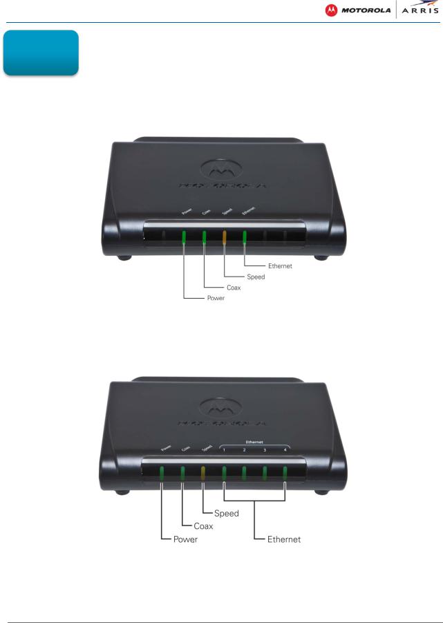
Figure 1 – SBM1100 Single-Port SMART Video Adapter Front View
Figure 2 – SBM1400 Four-Port SMART Video Adapter Front View
SBM1000 SMART Video Adapter Kit • User Guide |
4 |
590631-001-a |
|

Product Overview
|
Table 2 – SMART Video Adapter Front Panel LEDs |
|
|
LED |
LED INDICATORS & STATUS |
|
|
Power |
Green-SOLID: Indicates power is properly connected to the |
|
MoCA adapter and is finished booting |
|
Green-FLASHING: Indicates the MoCA adapter is booting |
|
FLASHING: Concurrent flashing indicates a validation failure |
|
of both the primary and secondary firmware image on the |
|
device |
|
|
Coax |
Green-SOLID: Indicates a network connection is made with |
|
one or more MoCA adapters |
|
Green-FLASHING: Indicates the MoCA adapter is passing |
|
data traffic on the MoCA network |
|
FLASHING: Concurrent flashing indicates a validation failure |
|
of both the primary and secondary firmware image on the |
|
device |
|
|
Speed |
Green-SOLID: Indicates a MoCA network connection with a |
|
225 Mbps or greater transfer rate with each MoCA-enabled |
|
device on the MoCA network |
|
Amber-SOLID: Indicates a MoCA network connection with at |
|
least a 150 to 225 Mbps transfer rate with each MoCA- |
|
enabled device on the MoCA network |
|
Amber-FLASHING: Indicates the MoCA adapter is searching |
|
for a MoCA network |
|
FLASHING: Concurrent flashing indicates a validation failure |
|
of both the primary and secondary firmware image on the |
|
device |
|
LED-OFF (Not lit): Indicates a MoCA network connection |
|
with less than 150 Mbps transfer rate with any single MoCA- |
|
enabled device on the MoCA network |
|
|
Ethernet |
Green-SOLID: Indicates the MoCA adapter has made a |
|
network connection with a network device on the indicated |
|
Ethernet port |
|
Green-FLASHING: Indicates the MoCA adapter is actively |
|
sending or receiving data over the indicated Ethernet port |
|
|
SBM1000 SMART Video Adapter Kit • User Guide |
5 |
590631-001-a |
|
Product Overview
Rear Panel
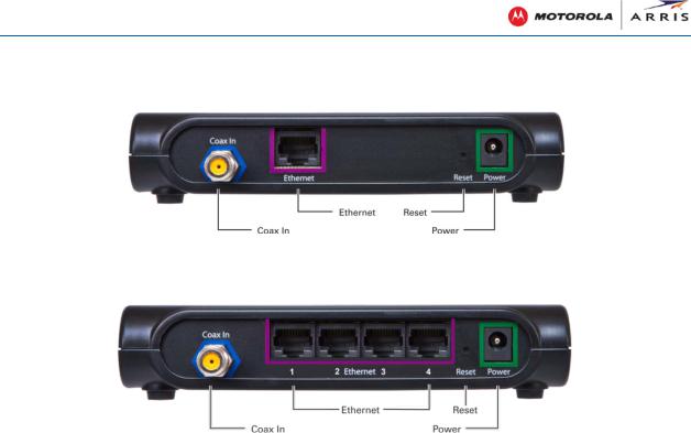
Figure 3 – SBM1100 One-Port SMART Video Adapter Rear View
|
Figure 4 – SBM1400 Four-Port SMART Video Adapter Rear View |
|
|
|
Table 3 – SMART Video Adapter Rear Panel Ports & Connectors |
|
|
|
|
|
|
|
PORT NAME |
DESCRIPTION |
|
|
|
|
|
|
Coax In |
Connects the MoCA adapter to the existing home coaxial cable network. |
|
|
|
|
|
|
Ethernet |
SBM1100: Ethernet port for a network connection to an Ethernet-enabled |
|
|
|
device such as a router, computer, tablet, Smart TV, set-top box (STB), or |
|
|
|
DVR. |
|
|
|
SBM1400: Four Ethernet ports for network connections to |
|
|
|
network-enabled devices such as a computer, game console, Blu-ray |
|
|
|
players, Smart TV, set-top box, or DVR. |
|
|
|
|
|
|
Reset |
Press and hold the Reset button for at least 2 seconds, but no more than |
|
|
|
five seconds to reboot the MoCA adapter and maintain the current MoCA |
|
|
|
adapter settings. |
|
|
|
If you experience a problem, you can push this recessed button to reset |
|
|
|
the MoCA adapter. |
|
|
|
Note: It is recommended that you do not power OFF the MoCA adapters, |
|
|
|
but use the Reset button. |
|
|
|
Press and hold the button for at least five seconds, but no more than 15 |
|
|
|
seconds to restore the MoCA adapter to its factory default configuration. |
|
|
|
|
|
|
Power |
Power connector for the +5VDC only power adapter |
|
|
|
|
|
|
|
|
|
SBM1000 SMART Video Adapter Kit • User Guide |
6 |
||
590631-001-a |
|
|
|

Installing the MoCA Adapters
3 |
Installing the MoCA |
|
Adapters |
||
|
This product is for indoor use only. Do not route the Ethernet cable(s) outside of the building. Exposure of the cables to lightning could create a safety hazard and damage the product.
Pre-installation Guidelines
You can quickly and easily set up your home MoCA network with the SBM1000 adapters. No additional wiring or hardware installation is required before starting this installation.
•For homes with a pre-existing MoCA network, you can install one or more SBM1000 adapters to extend your network.
•For homes with no pre-existing MoCA network or Ethernet-enabled devices, two or more SBM1000 adapters are needed to create a MoCA network.
Note: If there is no pre-existing MoCA network or MoCA-enabled set-top boxes in your home, you will need a minimum of two MoCA adapters to establish a MoCA Network.
•The rooms that you are planning to be part of the home network must have an existing coaxial network connection. If the coaxial connection can receive broadcast television service, make sure that it is NOT receiving more than one of the following:
οOver-the-Air (OTA) Television from an antenna
οDirecTV Satellite
οTelco or Cable TV on the same coaxial cable
Getting Started
The following is a list of the general steps that you will perform to create your home MoCA network using the SBM1000 SMART Video Adapters:
Note: All the recommended components you will need for this installation are included in the SBM1000 adapter box and are referenced as “included” throughout the installation procedures.
•Choose your type of network service provider from the Network Service Providers List.
•Determine the home network installation scenario that best fits your current home network configuration See Home Network Installation Scenarios for the list of available network installation options.
•Select the rooms that you want included in your home MoCA network. To qualify, each room must have an existing coaxial connection.
SBM1000 SMART Video Adapter Kit • User Guide |
7 |
590631-001-a |
|

Installing the MoCA Adapters
If there is no available cable connection in the room, then you must take the appropriate steps to install a cable connection. This may include reconfiguring the internal home coaxial wiring or adding external devices and cabling.
•Install the first MoCA adapter and your Smart TV, set-top box, gaming devices, or other Ethernet-enabled devices in the first qualified room.
•Install the second MoCA adapter and yourcomputer, cable modem/router, gateway, or other network access device in the second qualified room.
•Check the connections on both MoCA adapters. Make sure the Coax LEDs on both adapters light SOLID within five minutes. This indicates that a coaxial link was established between the two adapters.
Note: If the Coax LEDs do not light SOLID within five minutes, you will have to disconnect the power adapter on both MoCA adapters and then reconnect them. If the Coax LEDs still fail to light SOLID, see Troubleshooting Solutions for more information.
•Set up Internet access on both MoCA adapters - must have access to a computer on the network.
Network Service Providers List
The SBM1000 Video Adapters support the following network service providers:
•Traditional cable service provider
•Telco: Verizon FiOS or AT&T (U-verse)
•Satellite: DirectTV or Dish/EchoStar
•Over the Air (OTA)
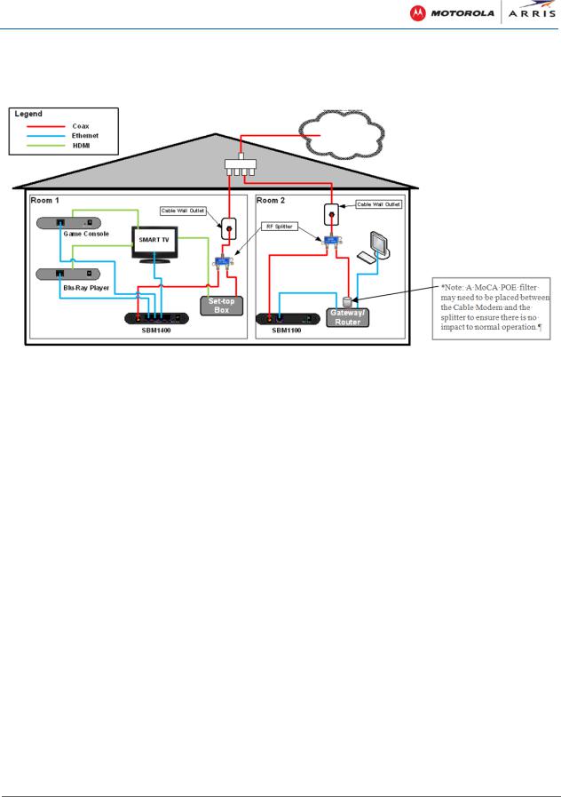
Home Network Installation Scenarios
The following is a list of the supported network installations based on your network service provider. See the flowchart on the next page to help determine the home network installation scenario that best fits your current home network configuration.
•Cable TV with a separate cable modem and router
•Cable TV with a combination cable modem and router (aka gateway) with no built-in MoCA capability
•Cable TV with a combination cable modem and router with built-in MoCA capability
•AT&T U-verse with a separate Wi-Fi router
•AT&T U-verse with an AT&T combination cable modem & router
•AT&T U-verse with an Ethernet cable-connected set-top box
•Verizon FiOS
•Dish/EchoStar
•DirecTV with single wire multi-switch (SWiM)
SBM1000 SMART Video Adapter Kit • User Guide |
8 |
590631-001-a |
|

Installing the MoCA Adapters
•DirecTV (non-SWiM)
•Over-the-Air (OTA) with installation of the MoCA filter included with the SBM1000 adapters
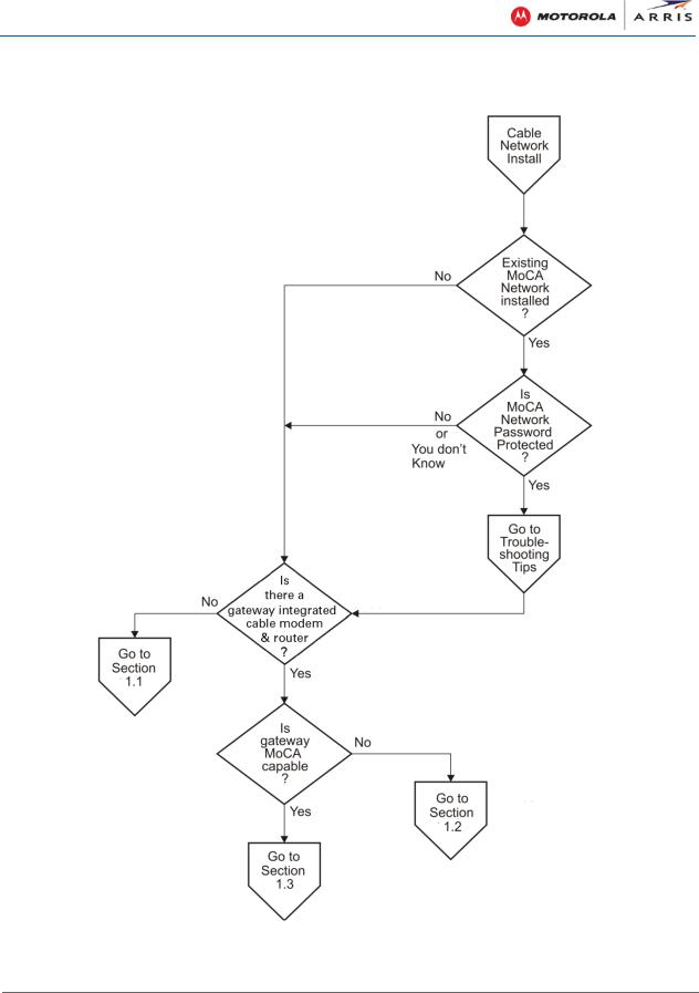
The following flowchart is provided to further help you determine the applicable installation procedure for your SBM1000 adapters. Please follow the questions in the flowchart:
Figure 5 – Installation Scenarios Flowchart
SBM1000 SMART Video Adapter Kit • User Guide |
9 |
590631-001-a |
|
Installing the MoCA Adapters
1 Cable Network Installations
Figure 6 – Cable Network Installations Flowchart
SBM1000 SMART Video Adapter Kit • User Guide |
10 |
590631-001-a |
|

Installing the MoCA Adapters
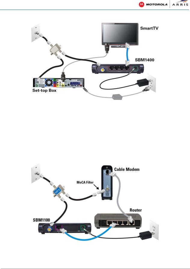
1.1 Installing for Cable with Separate Cable Modem & Router
Figure 7 – Cable Installation with Separate Cable Modem & Router
Follow these steps to set up the SBM1000 MoCA adapters in your home network, if you are receiving your Internet service through a cable modem and router:
1.Identify the rooms that you want to add to your home network and make sure there is a coaxial cable connection in each room.
2.Locate the cable wall outlet (or RF splitter) and electrical wall outlet in the first room (see Room 1 in Figure 7).
Note: Although the SBM1100 and SBM1400 adapters are interchangeable, the SBM1400 is typically located where more than one Ethernet connection is required (see Room 1 in Figure 7).
3.Check if the coaxial cable is connected to an RF splitter. If it is not, then disconnect the cable from your Smart TV or set-top box and connect it to the IN connector on one of the RF splitters (included).
4.Connect one of the coaxial cables (included) to the OUT connector on the RF splitter and your Smart TV or set-top box (see Figure 8).
Note: You can use either OUT connector on the RF splitter (included) for this installation.
5.Connect a second coaxial cable (included) to the other OUT connector on the RF splitter and the Coax In connector on the SBM1400 (see Figure 8).
SBM1000 SMART Video Adapter Kit • User Guide |
11 |
590631-001-a |
|
Installing the MoCA Adapters
Figure 8 – Room 1: SBM1400 Adapter Installation
6.Connect one of the Ethernet cables (included) to one of the Ethernet ports on the SBM1400 and the Ethernet/Network port on your Smart TV or other Smart device (see Figure 8).
Repeat for each additional SBM1400 Ethernet connection with other networked audio-visual devices, if applicable.
7.Connect one of the power adapters (included) to the Power port on the SBM1400 and plug it into an electrical wall outlet (see Figure 8).
8.Locate the cable wall outlet (or RF splitter) and electrical wall outlet in the second room (see Room 2 in Figure 7).
Figure 9 – Room 2: SBM1100 Adapter Installation with Cable Modem & Router
SBM1000 SMART Video Adapter Kit • User Guide |
12 |
590631-001-a |
|
Installing the MoCA Adapters
9.Check if the coaxial cable is connected to an RF splitter. If it is not, then disconnect the cable from your cable modem and connect it to the IN connector on the RF splitter (included); see Figure 9.
10.Connect a third coaxial cable (included) to one of the OUT connectors on the RF splitter (included) and the Cable connector on your cable modem (see Figure 9).
Notes:
οYou can use either OUT connector on the RF splitter (included) for this installation.
οYou may want to install a MoCA filter (included) between your cable modem and RF splitter (see Figure 9) to ensure maximum cable modem network performance.
11.Connect a fourth coaxial cable (included) to the other OUT connector on the RF splitter and the Coax In connector on the SBM1100 adapter (see Figure 9).
12.Connect an Ethernet cable to the Ethernet port on the SBM1100 adapter and one of the LAN Ethernet ports on your router (see Figure 9).
Note: Make sure your router (WAN port) and modem (Ethernet port) are connected via an Ethernet cable.
13.Connect one of the power adapters (included) to the Power port on the SBM1100 and plug it into an electrical wall outlet (see Figure 9).
οThe Coax LEDs on both MoCA adapters should turn ON within five minutes to indicate that a secure coaxial link was established between the two adapters.
οIf the Coax LED does not turn ON within five minutes, disconnect the power adapter from both MoCA adapters and then reconnect them, if the Coax LEDs still fail to turn ON, see Troubleshooting Solutions for more information.
14.Power ON your Smart TV, set-top box, laptop, and any other Ethernet-connected devices.
You can now configure your Smart TV and other Ethernet-enabled devices for Internet access through their related user interfaces.
See Configuring_MoCA_Adapters for more information on setting up the MoCA adapters.
SBM1000 SMART Video Adapter Kit • User Guide |
13 |
590631-001-a |
|
Installing the MoCA Adapters
1.2Installing for Cable with an Integrated Cable Modem & Router (without MoCA Capability)
Figure 10 – Cable/Telco Installation with Integrated Cable Modem & Router
Follow these steps to set up the SBM1000 MoCA adapters in your home network if you are receiving your Internet service through a gateway, also referred to as an integrated cable modem and router:
1.Identify the rooms that you want to add to your home network and make sure there is a coaxial cable connection in each room.
2.Locate the cable wall outlet (or RF splitter) and electrical wall outlet in the first room (see Room 1 in Figure 10).
Note: Although the SBM1100 and SBM1400 adapters are interchangeable, the SBM1400 is typically located where more than one Ethernet connection is required (see Room 1 in Figure 10).
3.Check if the coaxial cable is connected to an RF splitter. If it is not, then disconnect the cable from your Smart TV or set-top box and connect it to the IN connector on one of the RF splitters (included).
4.Connect one of the coaxial cables (included) to the OUT connector on the RF splitter and your Smart TV or set-top box (see Figure 11).
Note: You can use either OUT connector on the RF splitter (included) for this installation.
5.Connect a second coaxial cable (included) to the other OUT connector on the RF splitter and the Coax In connector on the SBM1400 (see Figure 11).
6.Connect one of the Ethernet cables (included) to one of the Ethernet ports on the SBM1400 and the Ethernet/Network port on your Smart TV or other Smart device (see Figure 11).
Repeat for each additional SBM1400 Ethernet connection with other networked audio-visual devices, if applicable.
SBM1000 SMART Video Adapter Kit • User Guide |
14 |
590631-001-a |
|

Installing the MoCA Adapters
Figure 11 – Room 1: SBM1400 Adapter Installation
7.Connect one of the power adapters (included) to the Power port on the SBM1400 and plug it into an electrical wall outlet (see Figure 11).
8.Locate the cable wall outlet (or RF splitter) and electrical wall outlet in the second room (see Room 2 in Figure 10).
Figure 12 – Room 2: SBM1100 Adapter Installation with Gateway
9.Check if the coaxial cable is connected to an RF splitter. If it is not, then disconnect the cable from your gateway and connect it to the IN connector on the RF splitter (included); see Figure 12.
10.Connect a third coaxial cable (included) to one of the OUT connectors on the RF splitter (included) and the Cable connector on your gateway (see Figure 12).
SBM1000 SMART Video Adapter Kit • User Guide |
15 |
590631-001-a |
|

Installing the MoCA Adapters
Notes:
οYou can use either OUT connector on the RF splitter (included) for this installation.
οYou may want to install a MoCA filter (included) between your gateway and RF splitter (see Figure 12) to ensure maximum cable modem network performance.
11.Connect a fourth coaxial cable (included) to the other OUT connector on the RF splitter and the Coax In connector on the SBM1100 adapter (see Figure 12).
12.Connect an Ethernet cable to the Ethernet port on the SBM1100 adapter and one of the LAN Ethernet ports on your gateway (see Figure 12).
13.Connect one of the power adapters (included) to the Power port on the SBM1100 and plug it into an electrical wall outlet (see Figure 12).
οThe Coax LEDs on both MoCA adapters should turn ON within five minutes to indicate that a secure coaxial link was established between the two adapters.
οIf the Coax LED does not turn ON within five minutes, disconnect the power adapter from both MoCA adapters and then reconnect them, if the Coax LEDs still fail to turn ON, see Troubleshooting Solutions for more information.
14.Power ON your Smart TV, set-top box, laptop, and any other Ethernet-connected devices.
You can now configure your Smart TV and other Ethernet-enabled devices for Internet access through their related user interfaces.
See Configure_MoCA_Adapters for more information on setting up the MoCA adapters.
SBM1000 SMART Video Adapter Kit • User Guide |
16 |
590631-001-a |
|

Installing the MoCA Adapters
1.3Installing for Cable with Integrated Cable Modem & Router (with MoCA)
Figure 13 – Cable/Telco Installation with Integrated Cable Modem/Router with MoCA
Follow these steps to set up the SBM1000 MoCA adapters in your home network, if you are receiving your Internet service through a gateway, also referred to as an integrated cable modem and router:
1.Identify the rooms that you want to add to your home network and make sure there is a coaxial cable connection in each room.
2.Locate the cable wall outlet (or RF splitter) and electrical wall outlet in the first room (see Room 1 in Figure 13).
Note: Although the SBM1100 and SBM1400 adapters are interchangeable, the SBM1400 is typically located where more than one Ethernet connection is required (see Room 1 in Figure 13).
3.Check if the coaxial cable is connected to an RF splitter. If it is not, then disconnect the cable from your Smart TV or set-top box and connect it to the IN connector on one of the RF splitters (included).
4.Connect one of the coaxial cables (included) to the OUT connector on the RF splitter and your Smart TV or set-top box (see Figure 14).
Note: You can use either OUT connector on the RF splitter (included) for this installation.
5.Connect a second coaxial cable (included) to the other OUT connector on the RF splitter and the Coax In connector on the SBM1400 (see Figure 14).
SBM1000 SMART Video Adapter Kit • User Guide |
17 |
590631-001-a |
|
Loading...