


NVG595
Table of contents
 Loading...
Administrator’s Handbook
ARRIS® Embedded Software Version 9.1.2
ARRIS® NVG595 Fiber Business Gateway

Administrator’s Handbook
Copyright
©ARRIS Enterprises, Inc. 2013 All rights reserved. No part of this publication may be reproduced in any form or by any means or
used to make any derivative work (such as translation, transformation, or adaptation) without written permission from ARRIS
Enterprises, Inc. (“ARRIS”). ARRIS reserves the right to revise this publication and to make changes in content from time to time
without obligation on the part of ARRIS to provide notification of such revision or change.
ARRIS and the ARRIS logo are all trademarks of ARRIS Enterprises, Inc. Other trademarks and trade names may be used in this
document to refer to either the entities claiming the marks and the names of their products. ARRIS disclaims proprietary interest in
the marks and names of others.
ARRIS provides this guide without warranty of any kind, implied or expressed, including, but not limited to, the implied warranties of
merchantability and fitness for a particular purpose. ARRIS may make improvements or changes in the product(s) described in this
manual at any time.
The capabilities, system requirements, and/or compatibility with third-party products described herein are subject to change without
notice.
EXCEPT AS INDICATED IN THE APPLICABLE SYSTEM PURCHASE AGREEMENT, THE SYSTEM, DOCUMENTATION AND
SERVICES ARE PROVIDED "AS IS", AS AVAILABLE, WITHOUT WARRANTY OF ANY KIND. ARRIS GROUP, INC. (“ARRIS”)
DOES NOT WARRANT THAT THE SYSTEM WILL MEET CUSTOMER'S REQUIREMENTS, OR THAT THEIR OPERATION WILL
BE UNINTERRUPTED OR ERROR-FREE, OR THAT ANY ERRORS CAN OR WILL BE FIXED. ARRIS HEREBY DISCLAIMS ALL
OTHER WARRANTIES, EXPRESS OR IMPLIED, ORAL OR WRITTEN, WITH RESPECT TO THE SYSTEM AND SERVICES
INCLUDING, WITHOUT LIMITATION, ALL IMPLIED WARRANTIES OF TITLE, NON-INFRINGEMENT, INTEGRATION,
MERCHANTABILITY OR FITNESS FOR ANY PARTICULAR PURPOSE AND ALL WARRANTIES ARISING FROM ANY COURSE
OF DEALING OR PERFORMANCE OR USAGE OF TRADE.
EXCEPT AS INDICATED IN THE APPLICABLE SYSTEM PURCHASE AGREEMENT, ARRIS SHALL NOT BE LIABLE
CONCERNING THE SYSTEM OR SUBJECT MATTER OF THIS DOCUMENTATION, REGARDLESS OF THE FORM OF ANY
CLAIM OR ACTION (WHETHER IN CONTRACT, NEGLIGENCE, STRICT LIABILITY OR OTHERWISE), FOR ANY (A) MATTER
BEYOND ITS REASONABLE CONTROL, (B) LOSS OR INACCURACY OF DATA, LOSS OR INTERRUPTION OF USE, OR
COST OF PROCURING SUBSTITUTE TECHNOLOGY, GOODS OR SERVICES, (C) INDIRECT, PUNITIVE, INCIDENTAL,
RELIANCE, SPECIAL, EXEMPLARY OR CONSEQUENTIAL DAMAGES INCLUDING, BUT NOT LIMITED TO, LOSS OF
BUSINESS, REVENUES, PROFITS OR GOODWILL, OR (D) DIRECT DAMAGES, IN THE AGGREGATE, IN EXCESS OF THE
FEES PAID TO IT HEREUNDER FOR THE SYSTEM OR SERVICE GIVING RISE TO SUCH DAMAGES DURING THE 12MONTH PERIOD PRIOR TO THE DATE THE CAUSE OF ACTION AROSE, EVEN IF COMPANY HAS BEEN ADVISED OF THE
POSSIBILITY OF SUCH DAMAGES. THESE LIMITATIONS ARE INDEPENDENT FROM ALL OTHER PROVISIONS OF THIS
AGREEMENT AND SHALL APPLY NOTWITHSTANDING THE FAILURE OF ANY REMEDY PROVIDED HEREIN.
All ARRIS products are furnished under a license agreement included with the product. If you are unable to locate a copy of the
license agreement, please contact ARRIS
Part number: 592050-002-00
Revision: 9.1.2

Table of Contents
Table of Contents
CHAPTER 1 - Introduction. . . . . . . . . . . . . . . . . . . . . . . . . . . . . . . . . . . . . 7
About ARRIS® Documentation . . . . . . . . . . . . . . . . . . . . . . . . . . . . . . . 7
Documentation Conventions . . . . . . . . . . . . . . . . . . . . . . . . . . . . . . . . . 8
eneral . . . . . . . . . . . . . . . . . . . . . . . . . . . . . . . . . . . . . . . . . . . . . . . . . . . . . . . . . . . 8
G
Internal Web Interface . . . . . . . . . . . . . . . . . . . . . . . . . . . . . . . . . . . . . . . . . . . . . . 8
Command Line Interface. . . . . . . . . . . . . . . . . . . . . . . . . . . . . . . . . . . . . . . . . . . . . 8
Organization . . . . . . . . . . . . . . . . . . . . . . . . . . . . . . . . . . . . . . . . . . . . . 9
A Word About Example Screens . . . . . . . . . . . . . . . . . . . . . . . . . . . . . . 9
CHAPTER 2 - Device Configuration. . . . . . . . . . . . . . . . . . . . . . . . . . . . . 11
Important Safety Instructions . . . . . . . . . . . . . . . . . . . . . . . . . . . . . . . 12
POWER SUPPLY INSTALLATION. . . . . . . . . . . . . . . . . . . . . . . . . . . . . . . . . . . . . . . 12
TELECOMMUNICATION INSTALLATION . . . . . . . . . . . . . . . . . . . . . . . . . . . . . . . .12
PRODUCT VENTILATION . . . . . . . . . . . . . . . . . . . . . . . . . . . . . . . . . . . . . . . . . . . . 12
ARRIS® Gateway Status Indicator Lights . . . . . . . . . . . . . . . . . . . . . . . 13
Set up the ARRIS Gateway . . . . . . . . . . . . . . . . . . . . . . . . . . . . . . . . . . 16
Microsoft Windows: . . . . . . . . . . . . . . . . . . . . . . . . . . . . . . . . . . . . . . . . . . . . . . . 16
Macintosh MacOS 8 or higher or Mac OS X: . . . . . . . . . . . . . . . . . . . . . . . . . . . . 18
Attaching a Fiber Optic Module . . . . . . . . . . . . . . . . . . . . . . . . . . . . . 19
Accessing the Web Management Interface . . . . . . . . . . . . . . . . . . . . 20
IP Diagnostics Page Redirect. . . . . . . . . . . . . . . . . . . . . . . . . . . . . . . . . . . . . . . . . 21
Offline Troubleshooting . . . . . . . . . . . . . . . . . . . . . . . . . . . . . . . . . . . . . . . . . . . . 21
Device Status page . . . . . . . . . . . . . . . . . . . . . . . . . . . . . . . . . . . . . . . 22
vice Access Code . . . . . . . . . . . . . . . . . . . . . . . . . . . . . . . . . . . . . . . . . . . . . . . . 22
De
Tab Bar . . . . . . . . . . . . . . . . . . . . . . . . . . . . . . . . . . . . . . . . . . . . . . . . . 24
Help . . . . . . . . . . . . . . . . . . . . . . . . . . . . . . . . . . . . . . . . . . . . . . . . . . . 24
Links Bar . . . . . . . . . . . . . . . . . . . . . . . . . . . . . . . . . . . . . . . . . . . . . . . 24
Device List . . . . . . . . . . . . . . . . . . . . . . . . . . . . . . . . . . . . . . . . . . . . . . . . 25
System Information . . . . . . . . . . . . . . . . . . . . . . . . . . . . . . . . . . . . . . . . . 27
Access Code . . . . . . . . . . . . . . . . . . . . . . . . . . . . . . . . . . . . . . . . . . . . . . . 28
Remote Access . . . . . . . . . . . . . . . . . . . . . . . . . . . . . . . . . . . . . . . . . . . . . 29
Restart Device . . . . . . . . . . . . . . . . . . . . . . . . . . . . . . . . . . . . . . . . . . . . . 31
Broadband . . . . . . . . . . . . . . . . . . . . . . . . . . . . . . . . . . . . . . . . . . . . . . 32
Configure . . . . . . . . . . . . . . . . . . . . . . . . . . . . . . . . . . . . . . . . . . . . . . . . . 34
Fiber Status . . . . . . . . . . . . . . . . . . . . . . . . . . . . . . . . . . . . . . . . . . . . . . . 35
Local Network . . . . . . . . . . . . . . . . . . . . . . . . . . . . . . . . . . . . . . . . . . . 37
Configure . . . . . . . . . . . . . . . . . . . . . . . . . . . . . . . . . . . . . . . . . . . . . . . . . 40
Wi-Fi . . . . . . . . . . . . . . . . . . . . . . . . . . . . . . . . . . . . . . . . . . . . . . . . . . . . . 41
Wi-Fi Security. . . . . . . . . . . . . . . . . . . . . . . . . . . . . . . . . . . . . . . . . . . . . . . . . . . . . 44
MAC Filtering . . . . . . . . . . . . . . . . . . . . . . . . . . . . . . . . . . . . . . . . . . . . . . 46
Wi-Fi Scan . . . . . . . . . . . . . . . . . . . . . . . . . . . . . . . . . . . . . . . . . . . . . . . . 47
Subnets & DHCP . . . . . . . . . . . . . . . . . . . . . . . . . . . . . . . . . . . . . . . . . . . 48

Administrator’s Handbook
IP Allocation . . . . . . . . . . . . . . . . . . . . . . . . . . . . . . . . . . . . . . . . . . . . . . . 50
Voice . . . . . . . . . . . . . . . . . . . . . . . . . . . . . . . . . . . . . . . . . . . . . . . . . . . 52
Line Details . . . . . . . . . . . . . . . . . . . . . . . . . . . . . . . . . . . . . . . . . . . . . . . . 53
Call Statistics . . . . . . . . . . . . . . . . . . . . . . . . . . . . . . . . . . . . . . . . . . . . . . . 54
Firewall . . . . . . . . . . . . . . . . . . . . . . . . . . . . . . . . . . . . . . . . . . . . . . . . .58
Packet Filter . . . . . . . . . . . . . . . . . . . . . . . . . . . . . . . . . . . . . . . . . . . . . . . 60
Working with Packet Filters . . . . . . . . . . . . . . . . . . . . . . . . . . . . . . . . . . . . . . . . . 62
NAT/Gaming . . . . . . . . . . . . . . . . . . . . . . . . . . . . . . . . . . . . . . . . . . . . . . . 69
Custom Services . . . . . . . . . . . . . . . . . . . . . . . . . . . . . . . . . . . . . . . . . . . . . . . . . . 71
Public Subnet Hosts . . . . . . . . . . . . . . . . . . . . . . . . . . . . . . . . . . . . . . . . . 74
P Passthrough . . . . . . . . . . . . . . . . . . . . . . . . . . . . . . . . . . . . . . . . . . . . . 75
I
Firewall Advanced . . . . . . . . . . . . . . . . . . . . . . . . . . . . . . . . . . . . . . . . . . 78
Diagnostics . . . . . . . . . . . . . . . . . . . . . . . . . . . . . . . . . . . . . . . . . . . . . .80
Logs . . . . . . . . . . . . . . . . . . . . . . . . . . . . . . . . . . . . . . . . . . . . . . . . . . . . . . 83
Update . . . . . . . . . . . . . . . . . . . . . . . . . . . . . . . . . . . . . . . . . . . . . . . . . . . 85
Resets . . . . . . . . . . . . . . . . . . . . . . . . . . . . . . . . . . . . . . . . . . . . . . . . . . . . 86
Syslog . . . . . . . . . . . . . . . . . . . . . . . . . . . . . . . . . . . . . . . . . . . . . . . . . . . . 87
Event Notifications . . . . . . . . . . . . . . . . . . . . . . . . . . . . . . . . . . . . . . . . . . 88
NAT Table . . . . . . . . . . . . . . . . . . . . . . . . . . . . . . . . . . . . . . . . . . . . . . . . . 89
CHAPTER 3 - Basic Troubleshooting . . . . . . . . . . . . . . . . . . . . . . . . . . . . 91
Status Indicator Lights . . . . . . . . . . . . . . . . . . . . . . . . . . . . . . . . . . . . .92
LED Function Summary Matrix. . . . . . . . . . . . . . . . . . . . . . . . . . . . . . . . . . . . . . . 95
Factory Reset Switch . . . . . . . . . . . . . . . . . . . . . . . . . . . . . . . . . . . . . .98
Log Event Messages . . . . . . . . . . . . . . . . . . . . . . . . . . . . . . . . . . . . . . .99
CHAPTER 4 - Command Line Interface . . . . . . . . . . . . . . . . . . . . . . . . . 103
Overview . . . . . . . . . . . . . . . . . . . . . . . . . . . . . . . . . . . . . . . . . . . . . .105
Starting and Ending a CLI Session . . . . . . . . . . . . . . . . . . . . . . . . . . . .107
ogging In. . . . . . . . . . . . . . . . . . . . . . . . . . . . . . . . . . . . . . . . . . . . . . . . . . . . . . . 107
L
Ending a CLI Session . . . . . . . . . . . . . . . . . . . . . . . . . . . . . . . . . . . . . . . . . . . . . . 107
Using the CLI Help Facility . . . . . . . . . . . . . . . . . . . . . . . . . . . . . . . . .108
About SHELL Commands . . . . . . . . . . . . . . . . . . . . . . . . . . . . . . . . . .108
SHELL Prompt . . . . . . . . . . . . . . . . . . . . . . . . . . . . . . . . . . . . . . . . . . . . . . . . . . . 108
SHELL Command Shortcuts. . . . . . . . . . . . . . . . . . . . . . . . . . . . . . . . . . . . . . . . . 108
SHELL Commands . . . . . . . . . . . . . . . . . . . . . . . . . . . . . . . . . . . . . . . . 109
Common Commands. . . . . . . . . . . . . . . . . . . . . . . . . . . . . . . . . . . . . . . . . . . . . . 109
WAN Commands . . . . . . . . . . . . . . . . . . . . . . . . . . . . . . . . . . . . . . . . . . . . . . . . . 118
About CONFIG Commands . . . . . . . . . . . . . . . . . . . . . . . . . . . . . . . . . 119
CONFIG Mode Prompt . . . . . . . . . . . . . . . . . . . . . . . . . . . . . . . . . . . . . . . . . . . . 119
Navigating the CONFIG Hierarchy . . . . . . . . . . . . . . . . . . . . . . . . . . . . . . . . . . . 119
Entering Commands in CONFIG Mode . . . . . . . . . . . . . . . . . . . . . . . . . . . . . . . 119
Guidelines: CONFIG Commands . . . . . . . . . . . . . . . . . . . . . . . . . . . . . . . . . . . . . 120
Displaying Current Gateway Settings. . . . . . . . . . . . . . . . . . . . . . . . . . . . . . . . . 120
Step Mode: A CLI Configuration Technique. . . . . . . . . . . . . . . . . . . . . . . . . . . . 120

Table of Contents
Validating Your Configuration. . . . . . . . . . . . . . . . . . . . . . . . . . . . . . . . . . . . . . . 121
CONFIG Commands . . . . . . . . . . . . . . . . . . . . . . . . . . . . . . . . . . . . . . 122
Connection commands . . . . . . . . . . . . . . . . . . . . . . . . . . . . . . . . . . . . . . . . . . . . 122
Filterset commands . . . . . . . . . . . . . . . . . . . . . . . . . . . . . . . . . . . . . . . . . . . . . . . 126
Global Filterset (“IPv6 Firewall”) commands . . . . . . . . . . . . . . . . . . . . . . . . . . 129
Queue commands . . . . . . . . . . . . . . . . . . . . . . . . . . . . . . . . . . . . . . . . . . . . . . . . 130
IP Gateway commands . . . . . . . . . . . . . . . . . . . . . . . . . . . . . . . . . . . . . . . . . . . . 133
IPv6 Commands . . . . . . . . . . . . . . . . . . . . . . . . . . . . . . . . . . . . . . . . . . . . . . . . . . 133
IP DNS commands . . . . . . . . . . . . . . . . . . . . . . . . . . . . . . . . . . . . . . . . . . . . . . . . 140
IP IGMP commands . . . . . . . . . . . . . . . . . . . . . . . . . . . . . . . . . . . . . . . . . . . . . . . 140
NTP commands . . . . . . . . . . . . . . . . . . . . . . . . . . . . . . . . . . . . . . . . . . . . . . . . . . 143
Application Layer Gateway (ALG) commands . . . . . . . . . . . . . . . . . . . . . . . . . . 143
Dynamic DNS Commands . . . . . . . . . . . . . . . . . . . . . . . . . . . . . . . . . . . . . . . . . . 144
Link commands . . . . . . . . . . . . . . . . . . . . . . . . . . . . . . . . . . . . . . . . . . . . . . . . . .144
Management commands . . . . . . . . . . . . . . . . . . . . . . . . . . . . . . . . . . . . . . . . . . 147
Remote access commands . . . . . . . . . . . . . . . . . . . . . . . . . . . . . . . . . . . . . . . . . 149
Physical interfaces commands . . . . . . . . . . . . . . . . . . . . . . . . . . . . . . . . . . . . . . 151
PPPoE relay commands. . . . . . . . . . . . . . . . . . . . . . . . . . . . . . . . . . . . . . . . . . . . 154
NAT Pinhole commands . . . . . . . . . . . . . . . . . . . . . . . . . . . . . . . . . . . . . . . . . . . 154
Security Stateful Packet Inspection (SPI) commands . . . . . . . . . . . . . . . . . . . . 155
VoIP commands . . . . . . . . . . . . . . . . . . . . . . . . . . . . . . . . . . . . . . . . . . . . . . . . . . 157
Targeted Ad Insertion commands . . . . . . . . . . . . . . . . . . . . . . . . . . . . . . . . . . . 167
System commands. . . . . . . . . . . . . . . . . . . . . . . . . . . . . . . . . . . . . . . . . . . . . . . . 169
Debug Commands . . . . . . . . . . . . . . . . . . . . . . . . . . . . . . . . . . . . . . . 174
claimer & Warning Text . . . . . . . . . . . . . . . . . . . . . . . . . . . . . . . . . . . . . . . . . 174
Dis
Commands . . . . . . . . . . . . . . . . . . . . . . . . . . . . . . . . . . . . . . . . . . . . . . . . . . . . . . 174
CLI CShell Commands (debug mode) . . . . . . . . . . . . . . . . . . . . . . . . . . . . . . . . 174
CHAPTER 5 - Technical Specifications and Safety Information. . . . . . 175
Description . . . . . . . . . . . . . . . . . . . . . . . . . . . . . . . . . . . . . . . . . . . . 175
ower Supply . . . . . . . . . . . . . . . . . . . . . . . . . . . . . . . . . . . . . . . . . . . . . . . . . . . .175
P
Environment. . . . . . . . . . . . . . . . . . . . . . . . . . . . . . . . . . . . . . . . . . . . . . . . . . . . . 175
Software and protocols. . . . . . . . . . . . . . . . . . . . . . . . . . . . . . . . . . . . . . . . . . . . 175
Agency approvals . . . . . . . . . . . . . . . . . . . . . . . . . . . . . . . . . . . . . . . 176
Manufacturer’s Declaration of Conformance . . . . . . . . . . . . . . . . . . 177
Important Safety Instructions . . . . . . . . . . . . . . . . . . . . . . . . . . . . . . 179
47 CFR Part 68 Information . . . . . . . . . . . . . . . . . . . . . . . . . . . . . . . . 180
FCC Requirements . . . . . . . . . . . . . . . . . . . . . . . . . . . . . . . . . . . . . . . . . . . . . . . . 180
FCC Statements . . . . . . . . . . . . . . . . . . . . . . . . . . . . . . . . . . . . . . . . . . . . . . . . . .180
RF Exposure Statement: . . . . . . . . . . . . . . . . . . . . . . . . . . . . . . . . . . 181
Electrical Safety Advisory . . . . . . . . . . . . . . . . . . . . . . . . . . . . . . . . . 181
Caring for the Environment by Recycling . . . . . . . . . . . . . . . . . . . . . 182
Beskyttelse af miljøet med genbrug . . . . . . . . . . . . . . . . . . . . . . . . . . . . . . . . . 182
Umweltschutz durch Recycling. . . . . . . . . . . . . . . . . . . . . . . . . . . . . . . . . . . . . . 182
Cuidar el medio ambiente mediante el reciclaje . . . . . . . . . . . . . . . . . . . . . . . 182
Recyclage pour le respect de l'environnement . . . . . . . . . . . . . . . . . . . . . . . . . 182
Milieubewust recycleren. . . . . . . . . . . . . . . . . . . . . . . . . . . . . . . . . . . . . . . . . . . 183
Dba³oÊç o Êrodowisko - recykling . . . . . . . . . . . . . . . . . . . . . . . . . . . . . . . . . . . 183

Administrator’s Handbook
Cuidando do meio ambiente através da reciclagem . . . . . . . . . . . . . . . . . . . . 183
Var rädd om miljön genom återvinning. . . . . . . . . . . . . . . . . . . . . . . . . . . . . . . 183
Copyright Acknowledgments . . . . . . . . . . . . . . . . . . . . . . . . . . . . . . .185
Open Source Software Information . . . . . . . . . . . . . . . . . . . . . . . . . . . . . . . . . . 185
Appendix A - ARRIS® Gateway Captive Portal Implementation . . . . . 209
Overview . . . . . . . . . . . . . . . . . . . . . . . . . . . . . . . . . . . . . . . . . . . . . .210
Captive Portal RPC . . . . . . . . . . . . . . . . . . . . . . . . . . . . . . . . . . . . . . . 211
_00D09E_GetCaptivePortalParams RPC:. . . . . . . . . . . . . . . . . . . . . . . . . . . . . 211
X
X_00D09E_SetCaptivePortalParams RPC: . . . . . . . . . . . . . . . . . . . . . . . . . . . . . 212
Appendix B - Quality of Service (QoS) Examples . . . . . . . . . . . . . . . . . 213
Overview . . . . . . . . . . . . . . . . . . . . . . . . . . . . . . . . . . . . . . . . . . . . . .214
Downstream QoS: Ethernet Switch . . . . . . . . . . . . . . . . . . . . . . . . . .216
Downstream QoS: Egress queues . . . . . . . . . . . . . . . . . . . . . . . . . . . .217
Index . . . . . . . . . . . . . . . . . . . . . . . . . . . . . . . . . . . . . . . . . . . . . . . . . . . 219

CHAPTER 1 Introduction
About ARRIS® Documentation
NOTE::
ARRIS provides a suite of technical information for its family of intelligent enterprise and consumer Gateways.
I
t consists of:
Administrator’s Handbook
Dedicated User Manuals
Specific White Papers
This guide describes the wide variety of features and functionality of the ARRIS® Gateway, when used in
Router mode. The ARRIS® Gateway may also be delivered in Bridge mode. In Bridge mode, the Gateway acts
as a pass-through device and allows the workstations on your LAN to have public addresses directly on the
Internet.
The documents are available in electronic form as Portable Document Format (PDF) files. They are viewed (and
printed) from Adobe Acrobat Reader, Exchange, or any other application that supports PDF files.
They are downloadable from the ARRIS website:
http://www.arrisi.com/consumer
7

Administrator’s Handbook
Documentation Conventions
General
This manual uses the following conventions to present information:
Convention (Typeface) Description
ans serif
bold s
u
underlined sans serif Web GUI page links
nderlined sans serif
derlined sans serif underlined sans serif
un
terminal
bold terminal
Italic Italic type indicates the complete titles of manuals.
Internal Web Interface
Convention (Graphics) Description
Menu commands and button names
Computer display text
User-entered text
Denotes an “excerpt” from a Web page or the visual truncation of a
Web page
Denotes an area of emphasis on a Web page
C
ommand Line Interface
Syntax conventions for the ARRIS® Gateway command line interface are as follows:
Convention Description
straight ([ ]) brackets in cmd line Optional command arguments
curly ({ }) brackets, with values sepa-
rated with vertical bars (|).
bold terminal type face
italic terminal type face
Alternative values for an argument are presented in curly ({ }) brackets, with values separated with vertical bars (|).
User-entered text
Variables for which you supply your own values
8

Organization
This guide consists of five chapters, two appendices, and an index. It is organized as follows:
Chapter 1, “Introduction” — Describes the ARRIS
structure of this guide. It gives a table of conventions.
Chapter 2, “Device Configuration” — Describes how to get up and running with your ARRIS® Gateway.
Chapter 3, “Basic Troubleshooting” — Gives some simple suggestions for troubleshooting problems with
your Gateway’s initial configuration.
Chapter 4, “Command Line Interface” — Describes all the current text-based commands for both the
HELL and CONFIG modes. A summary table and individual command examples for each mode is provided.
S
Chapter 5, “Technical Specifications and Safety Information” — Presents system and device specifica-
tions and important compliance and safety statements.
Appendix A ARRIS® Gateway Captive Portal Implementation — Describes the ARRIS® Gateway Captive
Portal Implementation
Appendix B Quality of Service (QoS) Examples — Describes the ARRIS® Gateway Quality of Service (QoS)
Implementation
®
document suite, the purpose of, the audience for, and
A Word About Example Screens
This manual contains many example screen illustrations. Since ARRIS® Gateways offer a wide variety of features
and functionality, the example screens shown may not appear exactly the same for your particular Gateway or
setup as they appear in this manual. The example screens are for illustrative and explanatory purposes, and
should not be construed to represent your own unique environment.
9

Administrator’s Handbook
10

CHAPTER 2 Device Configuration
Most users will find that the basic Quick Start configuration insert that is shipped with the device is all that
t
hey ever need to use. For more advanced users, this section provides a a rich set of features that can be used
for more in-depth configuration. The following topics cover installation in Router Mode.
This chapter covers:
“Important Safety Instructions” on page 12
“ARRIS® Gateway Status Indicator Lights” on page 13
“Set up the ARRIS Gateway” on page 16
“Accessing the Web Management Interface” on page 20
“Device Status page” on page 22
“Tab Bar” on page 24
“Broadband” on page 32
“Local Network” on page 37
“Wi-Fi” on page 41
“Voice” on page 52
“Firewall” on page 58
“Diagnostics” on page 80
11

Administrator’s Handbook
Important Safety Instructions
POWER SUPPLY INSTALLATION
Connect the power supply cord to the power jack on the ARRIS
priate electrical outlet. There is no power (on / off) switch to power off the device.
®
Gateway. Plug the power supply into an appro-
CAUTION:
Depending on the power supply provided with the product, either the direct plug-in power supply blades,
power supply cord plug or the appliance coupler serves as the mains power disconnect. It is important that
the direct plug-in power supply, socket-outlet or appliance coupler be located so it is readily accessible.
TELECOMMUNICATION INSTALLATION
When using your telephone equipment, basic safety precautions should always be followed to reduce the risk
f fire, electric shock and injury to persons, including the following:
o
Do not use this product near water, for example, near a bathtub, wash bowl, kitchen sink or laundry tub, in a
wet basement or near a swimming pool.
Avoid using a telephone (other than a cordless type) during an electrical storm. There may be a remote risk
of electrical shock from lightning.
Do not use the telephone to report a gas leak in the vicinity of the leak.
CAUTION: The external phone should be UL Listed and the connections should be made in accordance with
Article 800 of the NEC.
PRODUCT VENTILATION
The ARRIS® Gateway is intended for use in a business. Ambient temperatures around this product should not
exceed 104 F (40 C). It should not be used in locaƟons exposed to outside heat radiaƟon or trapping of its
own heat. When properly installed the product should have at least one inch of clearance on all sides except
the bottom and should not be placed inside tightly enclosed spaces unless proper ventilation is provided.
SAVE THESE INSTRUCTIONS
12

ARRIS® Gateway Status Indicator Lights
Side View
0OWER
%THERNET
7I&I
"ROABAND
%THERNET
"ROADBAND
&IBER
3ERVICE
0HONE
0HONE
703
0OWER
%THERNET
7I&I
"ROABAND
%THERNET
"ROADBAND
&IBER
3ERVICE
0HONE
0HONE
703
Colored LEDs on your ARRIS
LED Action
Solid Green = The device is powered.
Flashing Green = A Power-On Self-Test (POST) is in progress
Power*
*During
Firmware
Upgrade
During Boot
rocess
p
Flashing Red = A POST failure (not bootable) or device malfunction occurred.
Orange/Amber = during firmware upgrade (see below)
Off = The unit has no AC power.
During the software installation, you will lose internet and phone service. The LEDs will function as
follows:
1. As firmware is being loaded into flash, the LEDs will operate normally as described.
2. The installation will take a few minutes –
During this phase, the Power LED will flash Orange/Amber during firmware upgrade
(flash writing to memory) and all other LEDs will be off.
3. The Gateway will restart automatically.
As the device reboots, the POWER ON LED behavior will happen.
• Power LED = GREEN/FLASH
• All other LED = OFF
If the device does not boot, and fails its self test or fails to perform initial load of the bootloader:
• Power LED = RED/FLASH
• ALL other LED = OFF
If the device boots and then detects a failure:
Power LED = GREEN/FLASH starting POST and then all LEDs will FLASH RED, including Power LED.
®
Gateway indicate the status of various port activity.
ARRIS® Gateway NVG595 status indicator lights
Ethernet
Wi-Fi
Solid Green = Powered device connected to the associated port (includes devices with wake-on-LAN
capability where a slight voltage is supplied to the Ethernet connection).
Flickering Green = Activity seen from devices associated with the port. The flickering of the light is
synchronized to actual data traffic.
Off = The device is not powered, no cable or no powered devices connected to the associated ports.
Solid Green = Wi-Fi is powered.
Flickering Green = Activity seen from devices connected via Wi-Fi. The flickering of the light is syn-
chronized to actual data traffic.
Off = The device is not powered or no powered devices connected to the associated ports.
13

Administrator’s Handbook
LED A
Solid Green = Good broadband connection.
Flashing Green & Red = If the broadband connection fails to be established for more than three
consecutive minutes the LED switches to Flashing Green when attempting or waiting to establish
Broadband
Eth
ernet
Broadband
Fiber
Service
a broadband connection alternating with a five second steady Red. This pattern continues until the
broadband connection is successfully established.
Flashing Red = No signal on the line. This is only used when ther
ing sequence.
Off = The device is not powered.
Solid Green = Good broadband connection.
Flashing Green & Red = If the broadband connection fails to be established for more than three
consecutive minutes the LED switches to Flashing Green when attempting or waiting to establish
a broadband connection alternating with a five second steady Red. This pattern continues until the
broadband connection is successfully established.
Flashing Red = No signal on the line. This is only used when there is no signal, not during the train-
ing sequence.
Off = The device is not powered.
Solid Green = IP connected (The device has a WAN IP address from DHCP or 802.1x authentication
and the broadband connection is up)
Flashing Green = Attempting connection, attempting IEEE 802.1X authentication or attempting to
obtain DHCP information.
Red = Device attempted to become IP connected and failed (no DHCP response, 802.1x authentica-
tion failed, no IP address from IPCP, etc.). The Red state times out after two minutes and the Service
indicator light returns to the Off state.
Off = The device is not powered or the broadband connection is not present.
ction
e is no signal, not during the train-
Phone 1, 2
WPS
(opens after
using WPS
button)
Solid Green
Flashing Green = Indicates a telephone is off-hook on the associated VoIP line.
Off = VoIP not in use, line not registered or Gateway power off.
Solid Green = Wi-Fi Protected Setup has been completed successfully. It should stay on for 5 minutes
or until push button is pressed again.
Flashing Green = for 2 mins. Indicates when WPS is broadcasting.
Flashing Red = for 2 min, when there is a Session overlap detected (possible security risk) in scenario.
Solid Red = Error unrelated to security, such as failed to find any partner, or WPS is disabled. It should
stay Solid Red for 5 min or until push button is pressed again.
Off = The device is not powered, no cable or no powered devices connected to the associated ports.
= The associated VoIP line has been registered with a SIP proxy server.
14

ARRIS® Gateway NVG595 Rear View
LED Action
Orange/Amber when a Gigabit Ethernet device is connected to each port.
Ethernet
1, 2, 3, 4
Green when 10/100 Ethernet device is connected.
Flash for Ethernet traffic passing.
Off = The device is not powered, or no powered devices connected to the associated ports.
NOTE:
The NVG595 supports two VoIP lines over one RJ14 VoIP port. In order to con-
nect two phone lines the supplied inner/outer pair splitter adapters must be
attached to the RJ14 VoIP port in order to terminate both lines. This is a special-purpose splitter. You must only use the inner/outer pair splitter adapters
supplied by AT&T.
15
Administrator’s Handbook
Set up the ARRIS Gateway
Refer to your Quickstart Guide for instructions on how to connect your ARRIS
PC or local area network, and your Internet access point, whether it is a Fiber connection or a Gigabit Ethernet
connection . Different ARRIS® Gateway models are supplied for any of these connections. If Dynamic Addressing is not enabled on your PC, perform the following.
®
gateway to your power source,
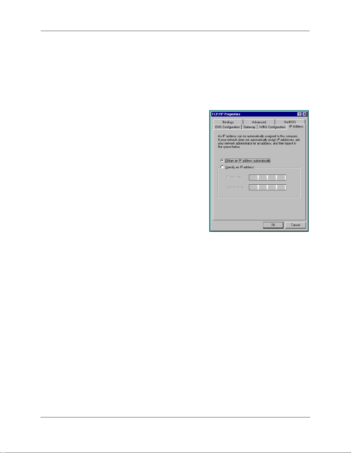
Microsoft Windows:
1. Navigate to the TCP/IP Properties Control Panel.
ome Windows versions follow a path like this:
S
Start menu -> Settings -> Control Panel -> Network (or Network
and Dial-up Connections -> Local Area Connection -> Properties)
-> TCP/IP [your_network_card] or Internet Protocol [TCP/IP] ->
Properties
Some Windows versions follow a path like this:
Start menu -> Control Panel -> Network and Internet Connections -> Network Connections -> Local Area Connection
-> Properties -> Internet Protocol [TCP/IP] -> Properties
2. Select Obtain an IP address automatically.
3. Select Obtain DNS server address automatically, if available.
4. Remove any previously configured Gateways, if available.
5. OK the settings. Restart if prompted.
Windows Vista and Windows 7 obtain an IP address automatically by default. You may not need to configure it
at all.
16

To check;
1
. Open the Networking Control Panel and select Internet Protocol Version 4 (TCP/IPv4).
2. Click the Properties button. The Internet Protocol Version 4 (TCP/IPv4) Properties window should appear
as shown.
3. Set the radio buttons to the values shown above, and click the OK button.
17
Administrator’s Handbook
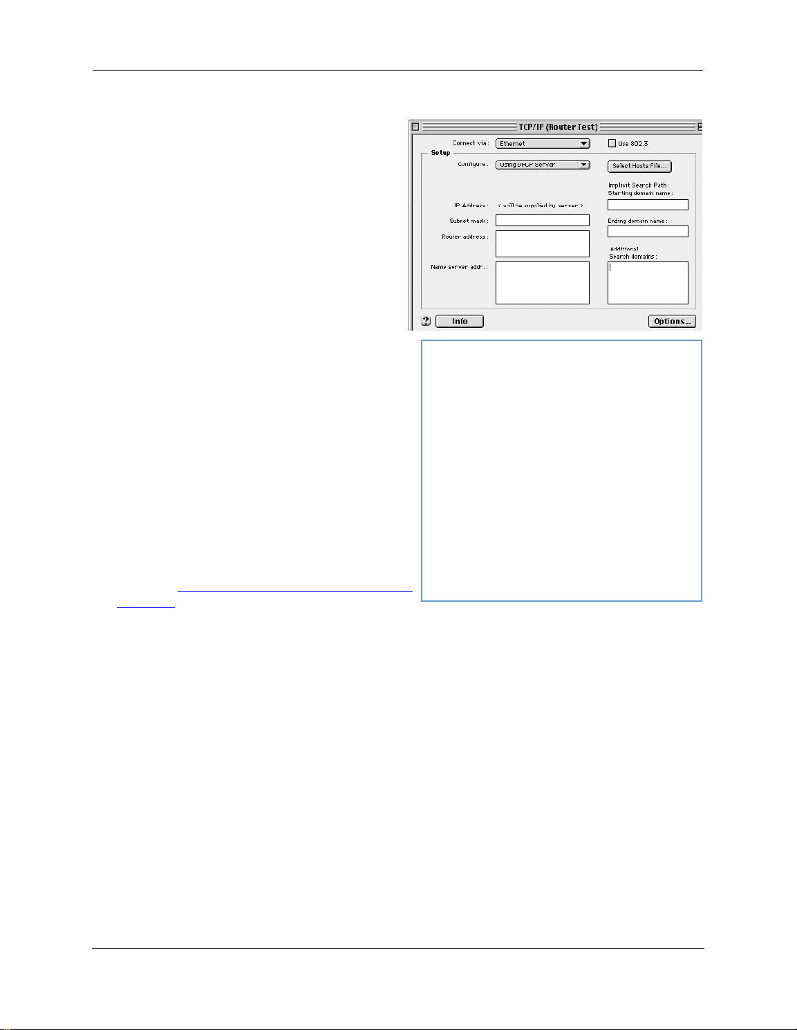
Macintosh MacOS 8 or higher or Mac OS X:
1. Access the TCP/IP or Network control panel.
M
acOS follows a path like this:
Apple Menu -> Control Panels -> TCP/IP Control
Panel
Mac OS X follows a path like this:
ple Menu -> System Preferences -> Network
Ap
2. Select Built-in Ethernet
3. Select Configure Using DHCP
4. Close and Save, if prompted.
Proceed to “
on page 20.
Accessing the Web Management Interface”
18

Attaching a Fiber Optic Module
The following procedure details how to attach an SFP SX/LX connector to the NVG595 and attach the fiber
o
ptic cable to the Optic module.
WARNING!
1. Insert the SFP SX/LX fiber optic module into the Fiber port on the rear of the NVG595. Push it in firmly until
it clicks. The label on the module should be facing upward when the module is inserted. Failure to ensure
this could cause damage to the module.
Laser output can cause serious eye damage. The lasers used in this device produce
ight that is invisible to the naked eye. Assume at all times that the fiber optic cables
l
and optical ports are radiating light energy. When connecting or handling the fiber
cables or connectors, it is imperative that no one looks into the tip of the fiber.
2. Remove the rubber protective cap from the end of the SFP SX/LX fiber optic module.
3. Remove the protective plastic caps from the end of the fiber cable and insert the fiber cable into the SFP SX/
LX fiber optic module. Push firmly until the latch on the end of the connector locks over the fiber cable.
19

Administrator’s Handbook
Accessing the Web Management Interface
1. Run your Web browser application, such as Firefox or Microsoft Internet Explorer, from the computer conn
ected to the ARRIS® Gateway.
2. Enter http://192.168.7.254 in the Location text box. Once the network type is determined, The Device Status
Page opens.
3. Check to make sure the Broadband and Service LEDs are lit GREEN to verify that the connection to the
nternet is active.
I
IP Diagnostics Page Redirect
In the event that your connection to the Internet fails, the Broadband LED will flash RED and you will be redi-
ected to the IP Diagnostics page.
r
Follow the on-screen troubleshooting suggestions.
20

For additional troubleshooting information, see “
page 91.
When your connection is restored or the problem is resolved, the Broadband LED will turn GREEN.
NOTE:
F
or AT&T this function is enabled by default. See the CLI command “set management lan-redirect
Offline Troubleshooting
If the WAN is down, the following information is displayed at the top of the page:
enable [ off | on ]” on page 150
Diagnostics” on page 80 and “Basic Troubleshooting” on
21

Administrator’s Handbook
Device Status page
After you have performed the basic Easy Login configuration, any time you log in to your ARRIS
will access the ARRIS® Gateway Home Page.
You access the Home Page by typing http://192.168.7.254 in your web browser’s location box.
Device Access Code
You may be required to provide your Device Access Code in order to access the web management configura-
ion pages. The Device Access Code is unique to your device. It is printed on a label on the bottom of the
t
Gateway.
®
Gateway you
Enter your Device Access Code and click the Continue
The Device Status Page opens.
22
Continue button.
ontinueContinue
C

DeviceStatusWindow
T
he Device Status displays the following information in the center section:
(icon) Field Description
(Broadband)
(Wi-Fi)
(Voice)
roadband
B
Connection
Status Your Wi-Fi signal may be ‘On’ or ‘Off’.
Band Indicates the current band the Wi-Fi is in, either 2.4 Ghz or 5.0 Ghz.
Network ID (SSID) This is the name or ID that is displayed to a client scan. The default
Authentication Type The type of Wi-Fi encryption security in use. May be Disabled, WPA
Password Wi-Fi network encryption key in use.
Line 1 Indication of VoIP or other phone connection.
Line 2 Indication of VoIP or other phone connection.
‘Waiting for ’ is displayed while the Gateway is training. This should
change to ‘Up’ within two minutes.
‘Up’ is displayed when the session is established.
‘Down’ indicates inability to establish a connection; possible line failure.
SSID for the Gateway is attxxx where xxx is the last 3 digits of the
serial number located on the side of the Gateway.
or WEP, Default Key or Manual.
Some fields may or may not display, depending on your particular setup.
Diagnostics button will connect you to the Troubleshoot page. See “Diagnostics” on page 80.
The Diagnostics
iagnosticsDiagnostics
D
The right-hand frame displays some links to commonly performed tasks for easy access.
Display additional troubleshooting steps - OR -
o to AT&T online support for troubleshooting and
G
repair »
This link will connect you to the IP Diagnostics page with
help for troubleshooting and the AT&T Help Desk information. See “IP Diagnostics Page Redirect” on page 20.
Modify your Wi-Fi security or settings »
This link will connect you to the Wi-Fi page. See “Wi-Fi”
on page 41.
Restart your device »
This link will connect you to the Restart Device page. See
“Restart Device” on page 31.
Find a computer on your Local Network »
This link will connect you to the Device List page. See
“Device List” on page 25.
Adjust firewall settings for gaming and applications »
This link will connect you to the NAT/Gaming page. See
“NAT/Gaming” on page 69.
23

Administrator’s Handbook
Tab Bar
The tab bar is located at the top of every page, allowing you to move freely about the site.
T
he tabs reveal a succession of pages that allow you to manage or configure several features of your Gateway.
Each tab is described in its own section.
Help
Help is provided in your Gateway. Help is available in the right hand frame on every page in the Web interface.
f the Show Help button is displayed, click it to open the Help. If the Hide Help button is displayed click it to
I
close the Help window.
Here is an example:
The page shown here is displayed when you are on the System Informa-
tion page.
Links Bar
The links bar at the top of each page allows you to configure different aspects of the features displayed on the
age. For example, on the Home Summary page, the button bar is shown below:
p
Click the links below to be taken to each section.
“Device Status page” on page 22
“Device List” on page 25
“System Information” on page 27
“Access Code” on page 28
“Remote Access” on page 29
“Restart Device” on page 31
24

Link: Device List
When you click the Device List
This view displays the following information:
Local Network Devices Displays the IPv4 Address, Network Name, and MAC Address of devices con-
MAC Address Client device’s unique hardware address.
IPv4 Address / Name Client device’s IP address or device network name.
Last Activity Date and time of last traffic for this client device
Status May be off or on.
Allocation Type of IP address assignment, for example, Static or DHCP.
Connection Type Type of connection, for example, Ethernet or Wi-Fi
Device List link, the Device List page opens.
Device List Device List
Local Network Devices
nected to this device on your local area network.
25

Administrator’s Handbook
For Wi-Fi client connections, the Device List displays the familiar bars indicating signal strength, as follows:
C
Click the Scan for Devices
Clear Device List button to update the Local Network summary.
lick the Clear Device List
lear Device ListClear Device List
C
Scan for Devices button to seek out other devices that have been connected since the last Local Net-
Scan for DevicesScan for Devices
work summary update.
26

Link: System Information
When you click the System Information
This view displays the following information:
Manufacturer This is the manufacturer’s identifier name.
Model Number This is the manufacturer’s model number.
Serial Number This is the unique serial number of your Gateway.
Software Version This is the version number of the current embedded software in your Gateway.
MAC Address Unique hardware address of this Gateway unit.
First Use Date Date and Time when the Gateway is first used. This field changes to the current date
Time Since Last Reboot Elapsed time since last reboot of the Gateway in days:hr:min:sec.
Current Date/Time Current system date and time in days:hr:min:sec.
Datapump Version Underlying operating system software datapump version
Legal Disclaimer Clicking the Licenses
System Information link, the System Information page opens.
System InformationSystem Information
System Information
and time after a reset to factory defaults.
Licenses link displays a listing of software copyright attributions also
ensesLicenses
Lic
shown here:“Copyright Acknowledgments” on page 186.
27

Administrator’s Handbook
Link: Access Code
Access to your Gateway is controlled through an account named admin. The default Admin password for your
Gateway is the unique Access Code printed on the label on the side or bottom of your Gateway.
As the Admin, you can change this password to a different one of your own choosing between 8 and 20 characters long. The new password must also include two characters from any these categories: alpha, number, and
special characters.
Example: “fru1tfl13s_likeabanana”
ter your Old Access Code, your New Access Code, and click the Use New Access Code
En
Use New Access Code button. The new Access
se New Access CodeUse New Access Code
U
Code takes effect immediately.
You can always return to the original default password by clicking the Use Default Access Code
Use Default Access Code button.
Use Default Access CodeUse Default Access Code
28

Link: Remote Access
The Remote Access page lets you grant access to your NVG595 Gateway to other users on the WAN. This function can be used for advanced troubleshooting or remote configuration.
WARNING
E
If Remote access is not currently enabled, the Remote Access page will let you configure and enable it. If
remote access has been enabled, the Remote Access Page will indicate that, and provides a button to disable
it.
nabling remote access allows anyone who knows or can determine the password, port ID, and URL
(address) of your NVG595 Gateway to view any configuration settings or change the operation of your gateway.
To enable Remote Access:
1. Enter a password. This password must be at least 8 characters long, and must include at least two of the following types of characters:
alphabetic (letter) characters,
numeric (number) characters,
special characters (! @ # $ % ^ & * , etc)
If necessary, set a custom port number for secure HTTP access to the NVG595 remote access session in the
2.
Port Value field.
3. Click the Access Type radio button to select the desired level of access:
Read only access - to allow the remote access session to view, but not change, the configuration and col-
lected statistics of the gateway.
Update access - to allow the session to make changes to the gateway’s configuration.
4. Click Enable Remote Access
The NVG595 updates the Remote Access page and displays the current remote access settings, shows the URL
that a remote access client must use to connect to the remote access session, and provides a button for ending
the remote access session. The remote access client will need to connect to the URL shown on the Remote
Access page, and will need to log in with the username “tech” and the password configured when access was
enabled.
Enable Remote Access.
Enable Remote AccessEnable Remote Access
29
Administrator’s Handbook
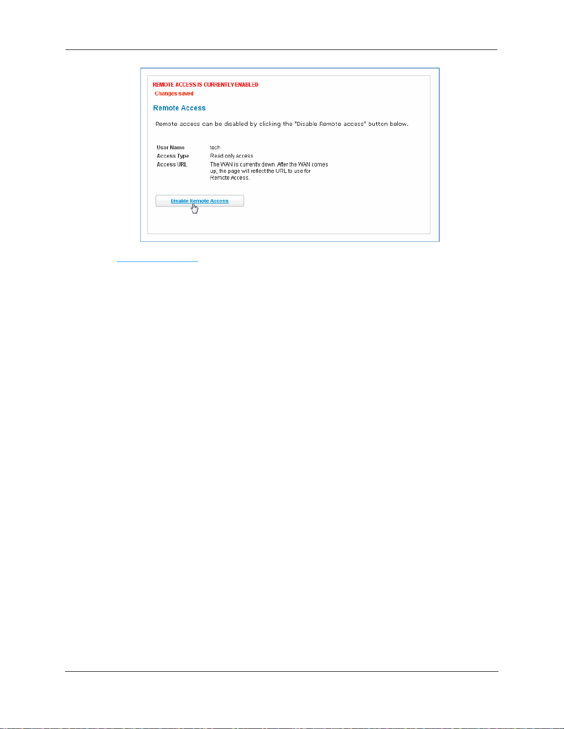
To end (disable) an existing remote access configuration:
C
lick the Disable Remote Access
Disable Remote Access button under the Access URL.
isable Remote AccessDisable Remote Access
D
30
Loading...