

Aprilia ETX 125 User Manual 1998
use and maintenance
aprilia
part# 8102852
ETX 125

© 1998 aprilia s.p.a. - Noale (VE)
This manual is to be considered an integral part of the vehicle,
which must be delivered complete with it also in case of resale.
aprilia s.p.a. reserves the right to modify its models at any time,
without prejudice to the main characteristics here described.
All rights as to electronic storage, reproduction and total or par-
tial adaptation, with any means, are reserved for all Countries.
The mention to products or services supplied by third parties is
made only for information purposes and is not binding in any
case.
aprilia s.p.a takes no responsibility as to the performance or the
use of said products.
First edition: march 1998
Reprint:
Produced and printed by:
Studio Tecno Public
Viale del Progresso - 37038 Soave (VR) - Italy
Tel. +39 (0)45 -76 11 911
Fax +39 (0)45 -76 12 241
www.stp.it
E-mail: customer@stp.it
On behalf of:
aprilia s.p.a.
via G. Galilei, 1 - 30033 Noale (VE) - Italy
Tel. +39 (0)41 - 58 29 111
Fax +39 (0)41 - 44 10 54
www.aprilia.com
use and maintenance
2
ETX 125

FOREWORD
c
★
Before starting the engine, carefully read this manual, paying
particular attention to the chapter "RIDING SAFELY".
Your and other people’s safety depends not only on your quickness of reflexes and on your agility, but also on what you know
about the vehicle, on its efficiency and on your knowledge of the
basic information for RIDING SAFELY. Therefore, get a thorough knowledge of the vehicle, in such a way as to be able to
drive in the traffic safely.
For the controls and repairs not expressly described in this manual, for the purchase of aprilia Genuine Spare Parts, accessories and other products, as well as for specific technical advice,
contact only aprilia Authorized Outlets and Official Dealers, who
can ensure you reliable and prompt servicing.
Thank you for choosing aprilia . We wish you a nice ride.
IMPORTANT:
When asking your Dealer for spare parts, specify the spare parts
code indicated on the SPARE PARTS IDENTIFICATION LABEL.
Write down the identification code in the space here below, in order to remember it also in case of loss or deterioration of the label.
The label is positioned under the left side cover, see p. 40 (REMOVING THE SIDE COVERS).
aprilia
GR NL CH DK J SGP PL IL ROK
MAL RCH BM USA AUS
CODICE RICAMBI spare parts code number
ABCDE
N˚
IUKAPSFB D F E
I.M.
Carefully observe the instructions preceded by the following
warning signs:
Safety norms and regulations to protect the driver
and other people from severe injuries or grave risks.
a
Indications to make the operations easier. Technical
information.
The operations preceded by this symbol must be repeated on the opposite side of the vehicle.
In this manual the various versions are indicated by the following
symbols:
optional
&
catalytic version
2
Italy version
I
United Kingdom version
U
Austria version
A
Portugal version
P
Finland version
"
Belgium version
B
Germany version
D
France version
F
Spain version
E
Greece version
G
Holland version
O
Switzerland version
C
Denmark version
£
Japan version
J
Singapore version
S
Poland version
V
Israel version
%
South Korea version
K
Malaysia version
M
Chile version
R
Bermuda version
Q
United States of America
-
version
Australia version
^
use and maintenance
ETX 125
3

TABLE OF CONTENTS
SAFE DRIVE .....................................................................................................5
SAFETY RULES.........................................................................................6
CLOTHING.................................................................................................9
ACCESSORIES........................................................................................10
LOAD........................................................................................................10
ARRANGEMENT OF THE MAIN ELEMENTS ...............................................12
ARRANGEMENT OF THE INSTRUMENTS ...................................................14
INSTRUMENTS AND INDICATORS ..............................................................14
INSTRUMENTS AND INDICATORS TABLE............................................15
MAIN INDEPENDENT CONTROLS ...............................................................16
CONTROLS ON THE LEFT SIDE OF THE HANDLEBAR.......................16
IGNITION SWITCH...................................................................................17
STEERING LOCK.....................................................................................17
AUXILIARY EQUIPMENT ...............................................................................18
GLOVE/TOOL KIT COMPARTMENT.......................................................18
CRASH HELMET HOOK..........................................................................18
ANTI-THEFT HOOK.................................................................................19
SPECIAL TOOLS
MAIN COMPONENTS .....................................................................................20
FUEL.........................................................................................................20
TRANSMISSION OIL................................................................................20
2 STROKE OIL TANK...............................................................................21
BRAKE FLUID - recommendations ..........................................................22
DISC BRAKES..........................................................................................22
FRONT BRAKE........................................................................................23
REAR BRAKE...........................................................................................24
ADJUSTING THE REAR BRAKE LEVER HEIGHT..................................25
ADJUSTING THE CLUTCH......................................................................26
TYRES......................................................................................................27
COOLANT ................................................................................................28
CATALYTIC SILENCER
INSTRUCTIONS FOR USE .............................................................................31
PRELIMINARY CHECKING OPERATIONS.............................................31
STARTING................................................................................................32
DEPARTURE AND DRIVE.......................................................................34
RUNNING-IN............................................................................................37
STOPPING...............................................................................................37
PARKING..................................................................................................38
POSITIONING THE VEHICLE ON THE STAND......................................38
SUGGESTIONS TO PREVENT THEFT...................................................38
MAINTENANCE ..............................................................................................39
REGULAR SERVICE INTERVALS CHART.............................................39
..............................................................................19
&
...................................................................30
2
IDENTIFICATION DATA..........................................................................40
REMOVING THE SIDE COVERS............................................................ 40
AIR CLEANER.........................................................................................41
CHECKING THE TRANSMISSION OIL LEVEL AND TOPPING UP....... 42
CHANGING THE TRANSMISSION OIL .................................................. 43
FRONT WHEEL.......................................................................................44
REAR WHEEL ......................................................................................... 46
DRIVE CHAIN..........................................................................................48
INSPECTING THE FRONT AND REAR SUSPENSIONS.......................50
REAR SUSPENSION...............................................................................51
CHECKING THE BRAKE PAD WEAR.....................................................52
ADJUSTING THE COLD START CONTROL (
IDLING ADJUSTMENT............................................................................53
ADJUSTING THE ACCELERATOR CONTROL......................................53
SPARK PLUG..........................................................................................54
BATTERY.................................................................................................55
LONG INACTIVITY OF THE BATTERY .................................................. 55
CHECKING AND CLEANING
THE TERMINALS .................................................................................... 56
REMOVING THE BATTERY.................................................................... 56
CHECKING THE ELECTROLYTE LEVEL............................................... 57
RECHARGING THE BATTERY...............................................................57
INSTALLING THE BATTERY .................................................................. 57
CHANGING THE FUSES.........................................................................58
CHECKING THE SIDE STAND AND THE SAFETY SWITCH ................ 59
CHECKING THE SWITCHES..................................................................60
ADJUSTING THE VERTICAL HEADLIGHT BEAM.................................61
BULBS ..................................................................................................... 61
CHANGING THE HEADLIGHT BULBS...................................................62
CHANGING THE DASHBOARD BULBS.................................................63
CHANGING THE FRONT AND REAR DIRECTION INDICATORS.........64
CHANGING THE REAR LIGHT BULB.....................................................64
TRANSPORT ..................................................................................................65
DRAINING THE FUEL TANK...................................................................65
CLEANING .....................................................................................................66
LONG PERIODS OF INACTIVITY...........................................................67
AFTER A PERIOD OF INACTIVITY ........................................................ 67
TECHNICAL DATA ........................................................................................68
LUBRICANT CHART ............................................................................... 72
Importers..................................................................................................73
WIRING DIAGRAM - ETX 125................................................................. 74
WIRING DIAGRAM KEY - ETX 125.........................................................75
)...................................52
e
use and maintenance
4
ETX 125
safe drive
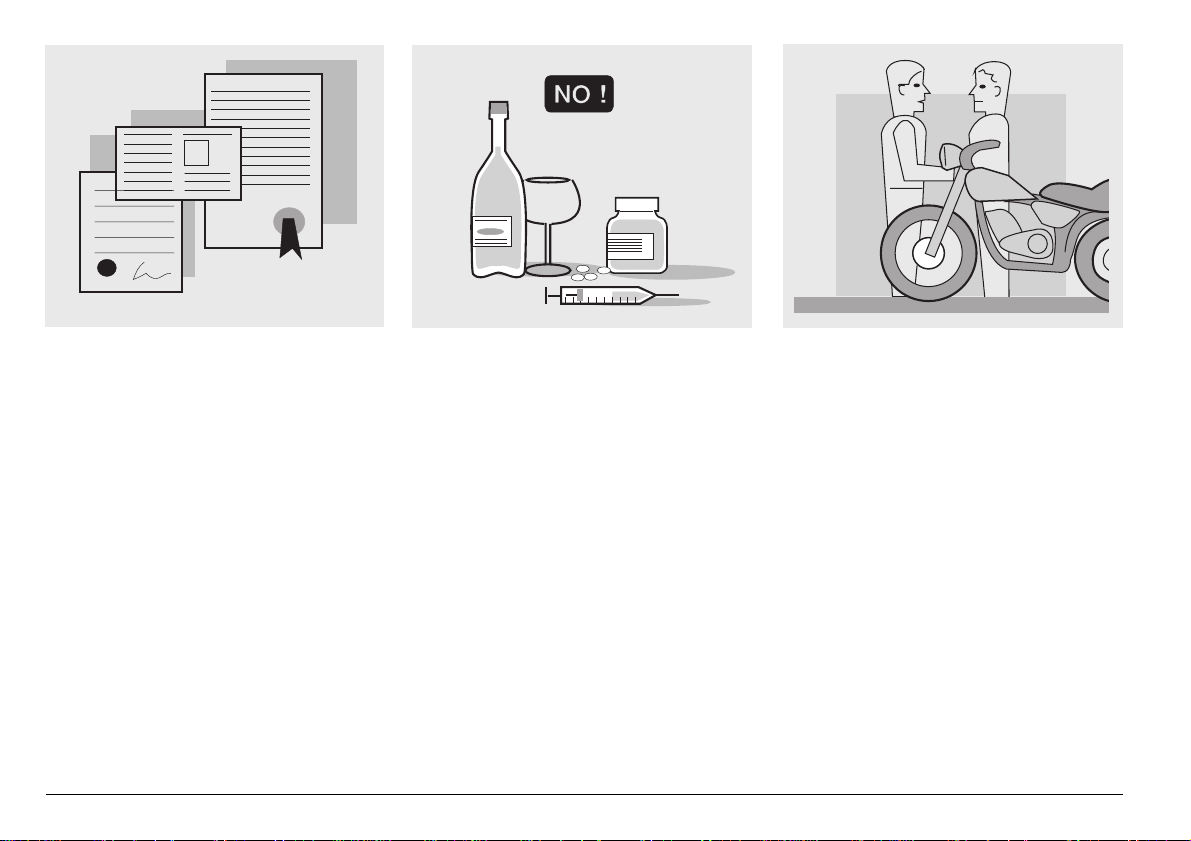
SAFETY RULES
To drive the vehicle it is necessary to be in
possession of all the requirements prescribed by law (driving licence, minimum
age, psychophysical ability, insurance,
state taxes, vehicle registration, number
plate, etc.).
Gradually get to know the vehicle by driving it first in areas with low traffic and/or private areas.
use and maintenance
6
ETX 125
The use of medicins, alcohol and drugs or
psychotropic substances notably increases
the risk of accidents.
Be sure that you are in good psychophysical conditions and fit for driving and pay
particular attention to physical weariness
and drowsiness.
Most road accidents are caused by the
driver’s lack of experience.
NEVER lend the vehicle to beginners and,
in any case, make sure that the driver has
all the requirements for driving.
¡
STOP150 m
150m
STOP
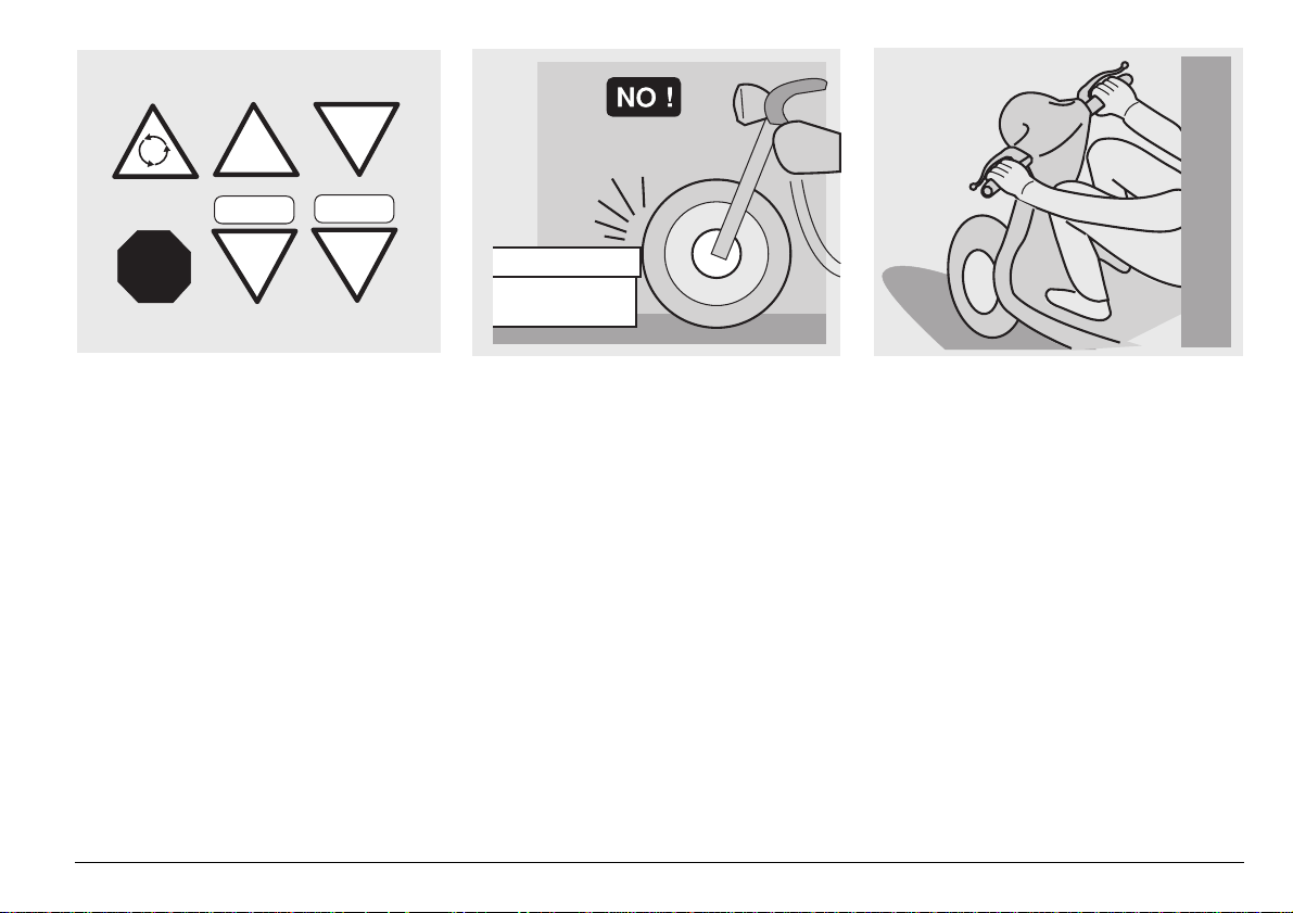
Rigorously observe all road signs and national and local road regulations.
Avoid abrupt movements that can be dangerous for yourself and other people (for
example: rearing up on the back wheel,
speeding, etc.), and give due consideration
to the road surface, visibility and other driving conditions.
Avoid obstacles that could damage the vehicle or make you lose control.
Avoid riding in the slipstream created by
preceding vehicles in order to increase
your speed.
Always drive with both hands on the handlebars and both feet on the footrests (or
on the rider’s footboards), in the correct
driving posture.
Avoid standing up or stretching your limbs
while driving.
use and maintenance
ETX 125
7
OIL
COOLER
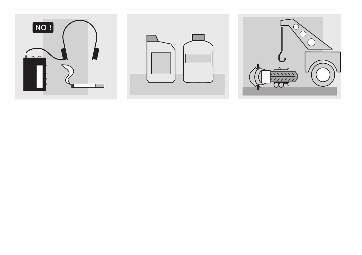
The driver should pay attention and avoid
distractions caused by people, things and
movements (never smoke, eat, drink, read,
etc.) while driving.
use and maintenance
8
ETX 125
Use only the vehicle’s specific fuels and lubricants indicated in the "LUBRICANT
CHART"; check the oil, fuel and coolant
levels regularly.
If the vehicle has been involved in an accident, make sure that no damage has occurred to the control levers, pipes, wires,
braking system and vital parts.
If necessary, have the vehicle inspected by
an aprilia Official Dealer, who should carefully check the frame, handlebars, suspensions, safety parts and all the devices that
you cannot check by yourself.
Always remember to report any malfunction to the technicians to help them in their
work.
Never use the vehicle when the amount of
damage it has suffered endangers your
safety.
A12
345
ONLY ORIGINALS
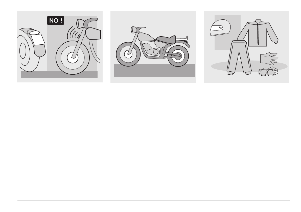
Never change the position, inclination or
colour of: number plate, direction indicators, lights and horns.
Any modification of the vehicle will result in
the invalidity of the guarantee.
Any modification of the vehicle and/or the
removal of original components can compromise vehicle performance levels and
safety or even make it illegal.
We recommend respecting all regulations
and national and local provisions regarding
the equipment of the vehicle.
In particular, avoid all modifications that increase the vehicle’s performance levels or
alter its original characteristics.
Never race with other vehicles.
CLOTHING
Before starting, always wear a correctly
fastened crash helmet. Make sure that it is
homologated, in good shape, of the right
size and that the visor is clean.
Wear protective clothing, preferably in light
and/or reflecting colours. In this way you
will make yourself more visible to the other
drivers, thus notably reducing the risk of
being knocked down, and you will be more
protected in case of fall.
This clothing should be very tight-fitting
and fastened at the wrists and ankles.
Strings, belts and ties should not be hanging loose; prevent these and other objects
from interfering with driving by getting entangled with moving parts or driving mechanisms.
use and maintenance
ETX 125
9
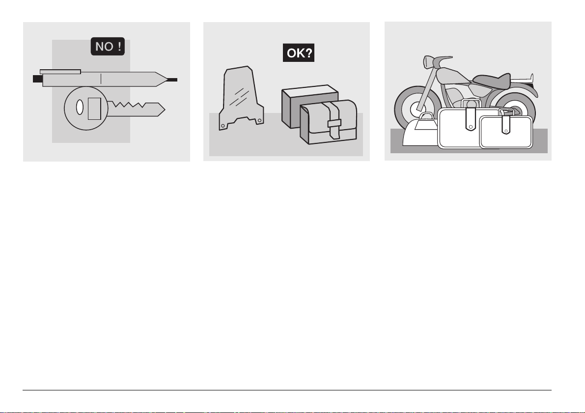
Do not keep objects that can be dangerous
in case of fall, for example pointed objects
like keys, pens, glass vials etc. in your
pockets (the same recommendations also
apply to passengers).
use and maintenance
10
ETX 125
ACCESSORIES
The owner of the vehicle is responsible for
the choice, installation and use of any accessory.
Avoid installing accessories that cover
horns or lights or that could impair their
functions, limit the suspension stroke and
the steering angle, hamper the operation of
the controls and reduce the distance from
the ground and the angle of inclination in
turns.
Avoid using accessories that hamper access to the controls, since this can prolong
reaction times during an emergency.
Large fairings and windscreens assembled
on the vehicle can produce aerodynamic
forces capable of compromising the stability of the vehicle while driving.
Make sure that the equipment is well fastened to the vehicle and not dangerous
during driving. Do not install electrical devices and do not modify those already existing to avoid electrical overloads, because the vehicle could suddenly stop or
there could be a dangerous current shortage in the horn and in the lights. aprilia
recommends the use of genuine accessories ( aprilia genuine accessories).
LOAD
Be careful and moderate when loading
your luggage. Keep any luggage loaded as
close as possible to the centre of the vehicle and distribute the load uniformly on
both sides, in order to reduce imbalance to
the minimum. Furthermore, make sure that
the load is firmly secured to the vehicle, especially during long trips.

KG!
Avoid hanging bulky, heavy and/or dangerous objects on the handlebars, mudguards
and forks, because the vehicle might respond more slowly in turns and its manoeuvrability could be unavoidably impaired.
Do not place bags that are too bulky on the
vehicle sides and do not ride with the crash
helmet hanging from its string, because it
could hit people or obstacles making you
lose control of the vehicle.
Do not carry any bag if it is not tightly secured to the vehicle.
Do not carry bags which protrude too much
from the luggage rack or which cover the
lights, horn or indicators.
Do not carry animals or children on the
glove compartment or on the luggage rack.
Do not exceed the maximum load allowed
for each side-bag.
When the vehicle is overloaded, its stability
and its manoeuvrability can be compromised.
use and maintenance
ETX 125
11
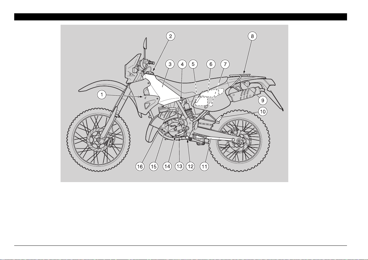
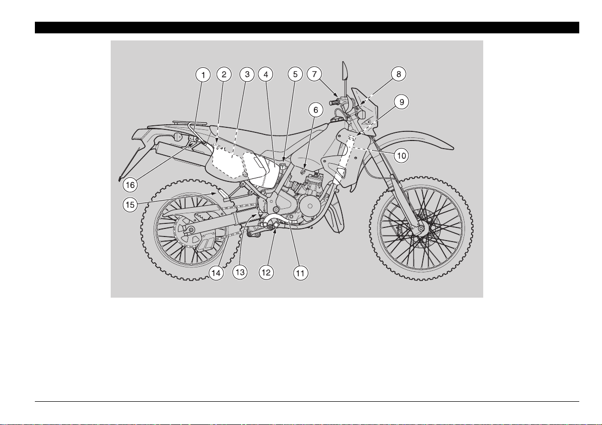
ARRANGEMENT OF THE MAIN ELEMENTS
KEY
1) Horn
2) Fuel tank plug
3) Fuel tank
4) Anti-theft hook (for the aprilia “BodyGuard” armored cable
&
)
5) Battery
7) Fuse carrier
8) Rear luggage rack
9) Passenger left grab rail
10) Passenger left footrest
(snapping, closed/open)
11) Side stand
6) Glove/tool kit compartment
12) Rider left footrest
(with spring, always open)
13) Transmission oil drain plug
14) Shifting lever
15) Transmission oil filling cap
16) Starting lever
use and maintenance
12
ETX 125
KEY
1) Passenger right grab rail
2) 2 stroke oil tank plug
3) 2 stroke oil tank
4) Air cleaner
5) Rear brake fluid tank
6) Fuel cock
7) Brake fluid reservoir (front brake)
8) Ignition switch/steering lock
9) Coolant radiator cap
10) Coolant radiator
11) Rear brake control lever
12) Rider right footrest
(with spring, always open)
13) Rear brake pump
14) Drive chain
15) Passenger right footrest
(snapping, closed/open)
16) Crash helmet hook
use and maintenance
ETX 125
13
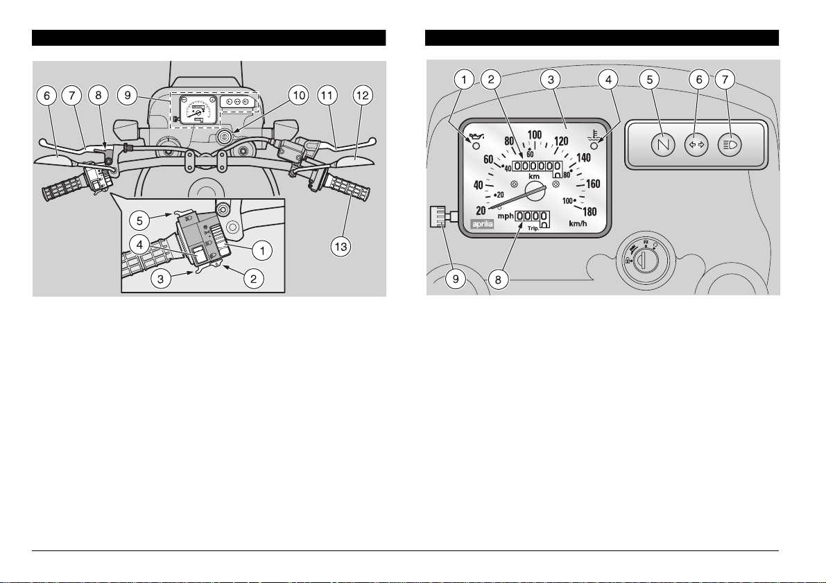
ARRANGEMENT OF THE INSTRUMENTS
INSTRUMENTS AND INDICATORS
KEY
1) Light switch (
2) Direction indicator switch (
3) Horn push button (
4) Dimmer switch (
5) High beam signalling push button (
6) Left rear-view mirror
7) Clutch lever
8) Cold start lever (
9) Instruments and indicators
10) Ignition switch/steering lock (
11) Front brake lever
12) Right rear-view mirror
13) Throttle grip
use and maintenance
14
o
ETX 125
-
b
e
p
f
)
-
- •)
)
a
)
c
)
n
KEY
1) Red 2 stroke oil reserve warning light (
2) Total kilometres odometer
3) Speedometer
4) Red coolant overheating warning light (
a
)
m
s
-
-
)
5) Green neutral indicator warning light (
6) Green direction indicator warning light (
7) Blue high beam warning light (
8) Partial kilometres odometer
9) Odometer trip control
a
j
)
h
)
q
)
c
)
)

INSTRUMENTS AND INDICATORS TABLE
Description Function
2 stroke oil reserve
warning light (
Comes on, for about 0.5 seconds, whenever the ignition switch is brought to position “
j
thus testing the correct operation of the bulb.
If the light does not come on in this phase, contact an aprilia Official Dealer .
a
n
If the warning light comes on during the normal operation of the engine, this
means that the 2 stroke oil reserve is being used; in this case, provide for topping up, see p. 21 (2 STROKE OIL TANK).
”,
Total kilometres odometer
Speedometer
Coolant overheating
warning light (
Neutral indicator warning light
Direction indicator
warning light (
High beam warning light (
Partial kilometres odometer
Odometer trip control
It indicates the total number of kilometres covered.
It indicates the driving speed.
It comes on when the coolant reaches or exceeds the limit temperature.
In this case, stop the engine and check the coolant level, see p. 28 (COOLANT).
h
a
It comes on when the gear is in neutral.
(
q)
Blinks when the direction indicators are on.
c)
Comes on when the headlight is in "high beam" position or when the high beam signalling is
a)
operated.
It indicates the partial number of kilometres covered.
To set it to zero, use the odometer trip control.
Rotate it anticlockwise to set the partial kilometres odometer to zero.
If the maximum allowed temperature is exceeded (the warning light comes on),
the engine may be seriously damaged.
use and maintenance
ETX 125
)
)
15
MAIN INDEPENDENT CONTROLS
c
c
o
p
3) HEADLIGHT SWITCH (
Before operating the light switch, make sure that
the dimmer switch (
When the light switch is in position “
When the switch is in position “
the dashboard light are on.
When the switch is in position “
dashboard light and the low or high beam are on.
By means of the dimmer switch (
operate the low or high beam.
-
•
-
)
-
) (6) is in position “
b
a
”, the lights are off.
•
p
”, the parking lights and
o
”, the parking lights, the
b
a
-
) (6) it is possible to
b
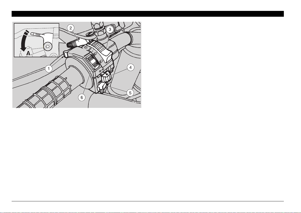
CONTROLS ON THE LEFT SIDE OF THE HANDLEBAR
The electrical parts work only when the ignition
switch is in position "
1) HIGH BEAM SIGNALLING PUSH BUTTON (
It makes it possible to use the high beam for signalling to
forthcoming vehicles while overtaking and in case of peril
and/or emergency.
2) COLD START LEVER (
16
The starter for the cold start of the engine is operated by
rotating the lever “
To disconnect the starter, return the lever “
position.
use and maintenance
e
ETX 125
n
".
e
” anticlockwise (Pos. A) .
)
a
” to its initial
e
”.
4) DIRECTION INDICATOR SWITCH (
To indicate the turn to the left, move the switch to the left; to
indicate the turn to the right, move the switch to the right.
To turn off the direction indicator, press the switch.
5) HORN PUSH BUTTON (
The horn is activated when the push button is pressed.
6) DIMMER SWITCH (
When the light switch (
)
)
)
dimmer switch is in position “
while if it is in position “
)
f
b
-
a
o
p
-
b
”, the low beam comes on.
c
•
-
) (3) is in position “
”, the high beam comes on,
a
o
”, if the
c
Position Function
Key
removal
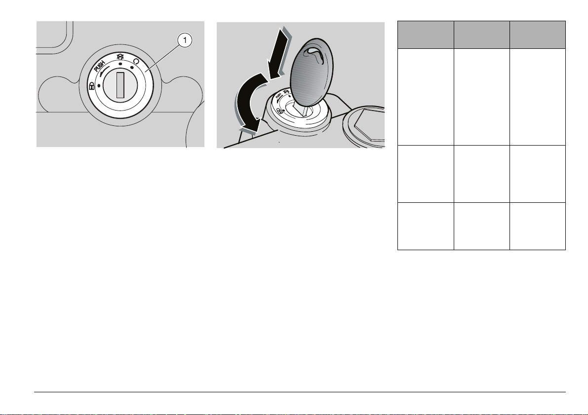
IGNITION SWITCH
The ignition switch (1) is positioned on the
upper plate of the steering column.
The key operates the ignition
switch/steering lock.
Two keys are supplied together with the
vehicle (one spare key).
STEERING LOCK
Never turn the key to position
"
s
a
vehicle.
OPERATION
To lock the steering:
◆
Turn the handlebar completely leftwards.
◆
Turn the key to position “
c
◆
Press and rotate the key anticlockwise
(leftwards), steer the handlebar slowly
until the key reaches position “
◆
Extract the key.
" in running conditions, in or-
der to avoid losing control of the
m
Turn the key and steer the handlebar at the same time.
s
”.
s
Steering
lock
m
n
The steering is
locked.
It is neither
possible to
start the
engine, nor
to switch on
the lights.
Neither the
engine, nor
the lights
can be
switched on.
The engine
and the
lights can be
switched on.
It is possible to
remove the
key.
It is possible to
remove the
key.
It is not possible to
remove the
key.
use and maintenance
ETX 125
”.
17
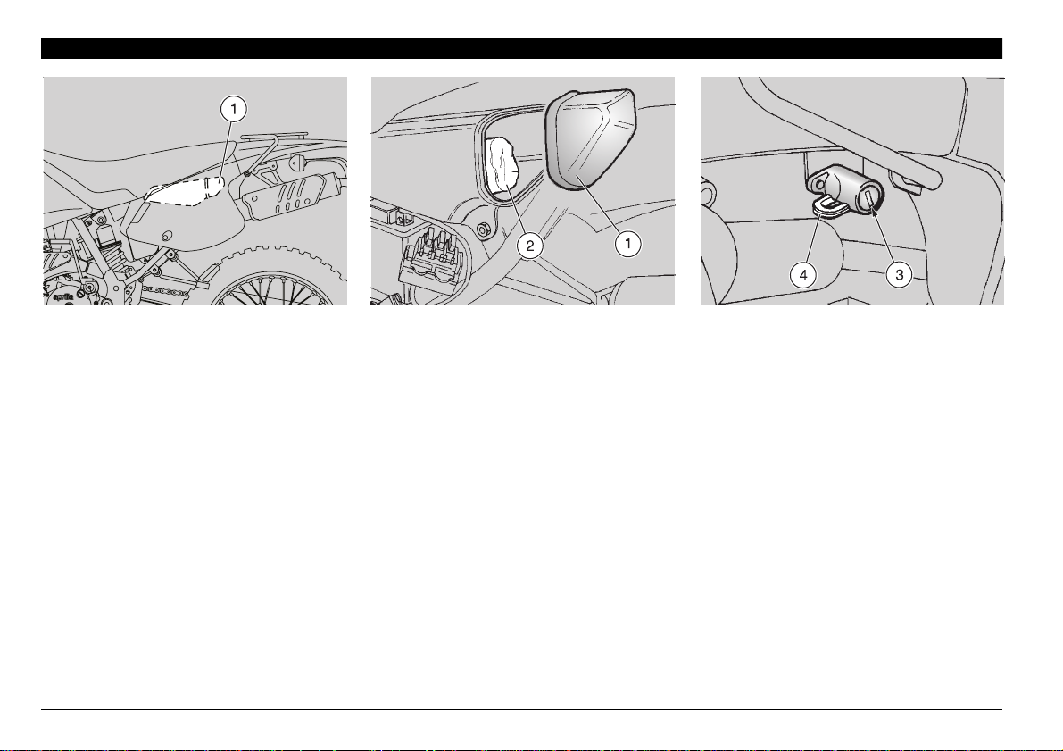
AUXILIARY EQUIPMENT
GLOVE/TOOL KIT COMPARTMENT
The glove/tool kit compartment is
positioned under the left side cover; to
reach it:
◆
Remove the left side cover, see p. 40
(REMOVING THE SIDE COVERS).
◆
Withdraw the compartment cover from
behind (1).
use and maintenance
18
ETX 125
The tool kit (2) includes:
– n˚ 1 tool case
– n˚ 1 4 mm bent Allen spanner
– n˚ 1 5 mm bent Allen spanner
– n˚ 1 6 mm bent Allen spanner
– n˚ 1 8 mm bent Allen spanner
– n˚ 1 7x8mm double fork spanner
– n˚ 1 10x13 mm double fork spanner
– n˚ 1 19 mm fork spanner
– n˚ 1 21x24 mm double socket spanner
– n˚ 1 cross-/cut-headed screwdriver
– n˚ 1 screwdriver handle
– n˚ 1 3x70 mm cross-headed screwdriver
Max. allowed weight: 1.5 kg
CRASH HELMET HOOK
Thanks to the crash helmet hook, you no
longer have to carry the crash helmet with
you every time you park the vehicle.
Do not ride with the crash helmet
hanging from the hook, as this
a
safety.
To hang the crash helmet, proceed as
follows:
◆
◆
◆
◆
may seriously compromise your
Insert the key in the lock (3).
Rotate the key clockwise.
Pass the crash helmet cable through the
hook (4).
Rotate the key anticlockwise.
Make sure that you have correctly
c
closed the hook (4).
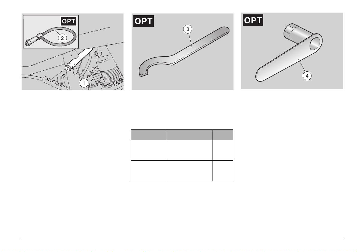
ANTI-THEFT HOOK
The anti-theft hook (1) is positioned on the
left side of the vehicle.
To prevent the vehicle from being stolen, it
is advisable to secure it with the aprilia
“Body-Guard” armored cable
available at any aprilia Official Dealer.
Do not use the hook to lift the
vehicle or for any purpose other
than securing the vehicle once it
a
has been parked.
&
(2),
SPECIAL TOOLS
To perform some specific operations, it is
advisable to use the following special
tools (to be requested to an aprilia Official
Dealer ):
Tool Operations Page
Square pin
spanner (3)
Special
socket
spanner (4)
&
Rear shock
absorber ring
adjustment.
Clutch clearance
adjustment. 26
51
use and maintenance
ETX 125
19
MAIN COMPONENTS
FUEL
The fuel used for internal combustion engines is extremely in-
a
ditions it can become explosive. It is
important to carry out the refuelling and
the maintenance operations in a wellventilated area, with the engine off. Do
not smoke while refuelling or near fuel
vapours, in any case avoid any contact
with naked flames, sparks and any other heat source to prevent the fuel from
catching fire or from exploding. Further,
prevent fuel from flowing out of the fuel
filler, as it could catch fire when getting
in contact with the red-hot surfaces of
the engine.
In case some fuel has accidentally been
spilt, make sure that the area has completely dried before starting the vehicle.
Since petrol expands under the heat of
the sun and due to the effects of sun radiation, never fill the tank to the brim.
Screw the plug up carefully after refuelling. Avoid any contact of the fuel with
the skin and the inhalation of vapours;
do not swallow fuel or pour it from a receptacle into another by means of a
tube.
flammable and in particular con-
DO NOT DISPOSE OF FUEL
IN THE ENVIRONMENT
KEEP AWAY FROM CHILDREN
Use only premium grade petrol (4 Stars
), in conformity with the DIN 51600
U
standard, min. O.N. 98 (N.O.R.M.) and 88
(N.O.M.M.).
Use only unleaded petrol, in conformity
2
with the DIN 51607 standard, min. O.N. 95
(N.O.R.M.) and 85 (N.O.M.M.).
FUEL TANK CAPACITY
(reserve included): 11
TANK RESERVE: 4
serve)
To refuel, proceed as follows:
◆
Unscrew and remove the fuel tank plug
(1).
◆
Refuel.
l
(mechanical re-
l
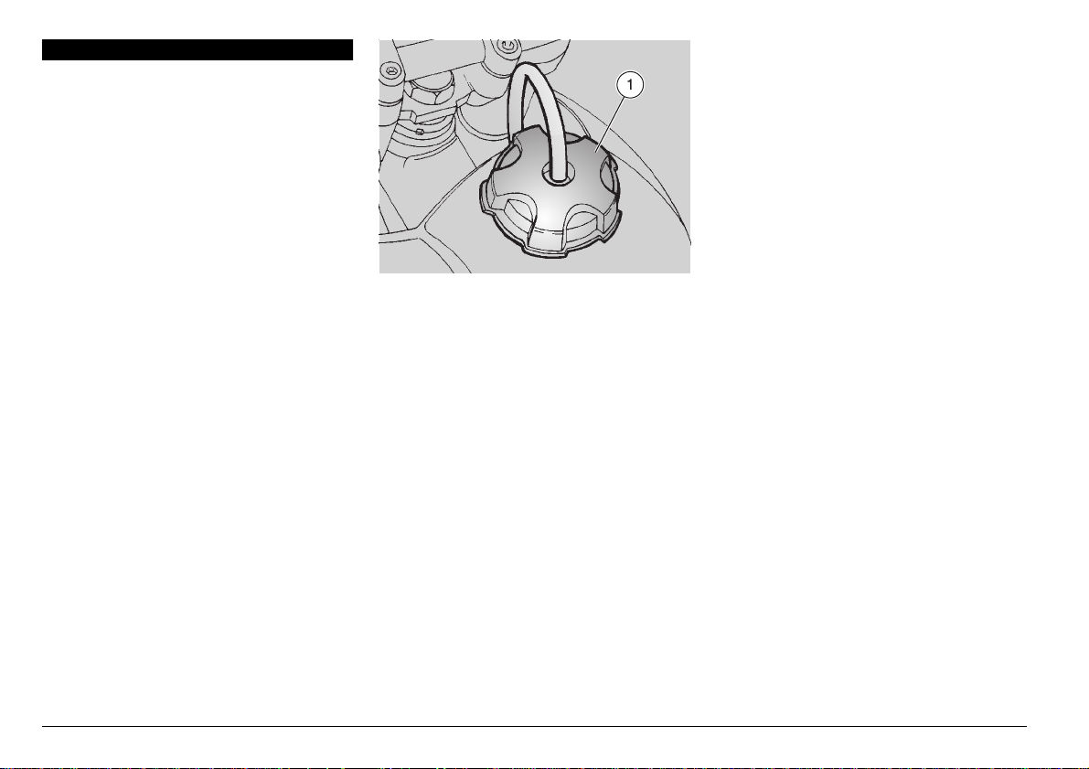
TRANSMISSION OIL
c
Check the transmission oil level every
4000 km, see p. 42 (CHECKING THE
TRANSMISSION OIL LEVEL AND TOPPING UP).
Change the transmission oil after the first
1000 km and successively every 12000
km, see p. 43 (CHANGING THE TRANSMISSION OIL).
Wash your hands carefully after using
the oil.
Do not dispose of the oil in the environment.
Put it in a sealed container and take it to
the filling station where you usually buy
it or to an oil salvage center.
In case any maintenance operation has
to be carried out, it is advisable to use
latex gloves.
Remember: 1 mile = 1.6 km
1 km = 0.625 miles
Use high-quality 75W-90 oil, see
c
p. 72 (LUBRICANT CHART).
Engine oil can cause serious
damage to the skin if handled
a
every day and for long periods.
use and maintenance
20
ETX 125
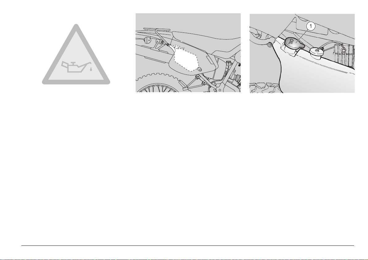
2 STROKE OIL TANK
c
Top up the 2 stroke oil tank every 500 km.
The vehicle is provided with a separate
mixer that ensures the mixing of petrol
and oil for the engine lubrication, see p. 72
(LUBRICANT CHART).
The 2 stroke oil reserve is indicated by the
coming on of the 2 stroke oil reserve warning light “
see p. 15 (INSTRUMENTS AND INDICATORS TABLE).
Remember: 1 mile = 1.6 km
1 km = 0.625 miles
” positioned on the dashboard,
j
The use of the vehicle without 2
a
If you run out of oil in the 2 stroke oil
tank or if the 2 stroke oil pipe has been
removed, contact an
Dealer , who will provide for bleeding
the system.
This operation is indispensable, since
the running of the engine with air in the
2 stroke oil system may result in serious damage to the engine.
stroke oil seriously damages the
engine.
aprilia
Official
To introduce the 2 stroke oil in the tank,
proceed as follows:
◆
Remove the right side cover, see p. 40
(REMOVING THE SIDE COVERS).
◆
Remove the plug (1).
TANK CAPACITY: 1.4
TANK RESERVE: 0.5
Carefully wash your hands after
a
in the environment.
KEEP AWAY FROM CHILDREN
handling the oil.
Do not dispose of the 2 stroke oil
l
l
use and maintenance
ETX 125
21

BRAKE FLUID - recommendations
c
This vehicle is provided with
separate hydraulic circuits.
The following information refers to a
single braking system, but is valid for
both.
lic system.
For any doubt regarding the perfect
functioning of the braking system and
in case you are not able to carry out the
usual checking operations, contact
your
front and rear disc brakes, with
Sudden resistance or clearance
problems on the brake lever may
a
be due to troubles in the hydrau-
aprilia
Official Dealer .
Make sure that the brake discs
are neither oily nor greasy, espe-
a
a
cially after maintenance or
When using the brake fluid, take
care not to spill it on the plastic
or painted parts, since it
checking operations.
Check that the brake cables are neither
twisted nor worn out.
Prevent water or dust from accidentally
getting into the circuit.
In case maintenance operations are to
be performed on the hydraulic circuit, it
is advisable to use latex gloves.
If the brake fluid gets in contact with the
skin or the eyes, it can cause serious irritations.
Carefully wash the parts of your body
that get in contact with the liquid.
Consult a doctor or an oculist if the liquid gets in contact with your eyes.
Do not dispose of the brake fluid in the
environment.
KEEP AWAY FROM CHILDREN
damages them irreparably.
DISC BRAKES
The brakes are the parts that
most ensure your safety and for
a
perfectly working; check them before
every trip.
The brake fluid must be changed once a
year by an
Use brake fluid of the type specified in
the lubricant chart, see p. 72 (LUBRICANT CHART).
When the disc pads wear out, the level of
the fluid inside the reservoir decreases to
automatically compensate for their wear.
The front brake reservoir is positioned
near the front brake lever coupling.
The rear brake reservoir is positioned on
the right side of the vehicle, before the air
filter casing.
Periodically check the brake fluid level in
the tanks, see p. 23 (FRONT BRAKE),
p. 24 (REAR BRAKE) and the wear of the
pads, see p. 52 (CHECKING THE BRAKE
PAD WEAR).
this reason they must always be
aprilia
Official Dealer .
22
use and maintenance
ETX 125
FRONT BRAKE
Carefully read p. 22 (BRAKE FLUID - recommendations) and (DISC BRAKES).
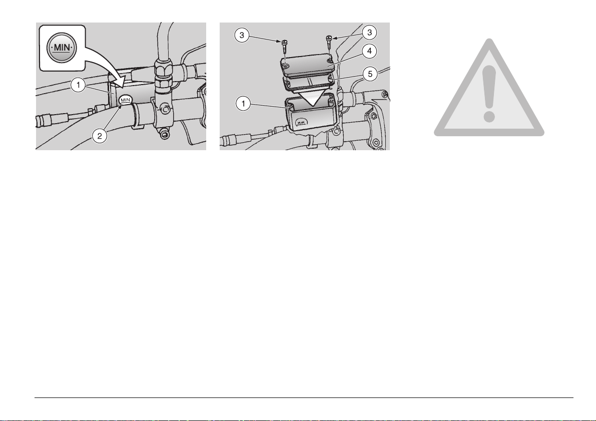
CHECKING
Position the vehicle on firm and
c
flat ground.
To check the brake fluid level, proceed as
follows:
◆
Position the vehicle on the stand.
◆
Rotate the handlebar leftwards, so that
the fluid contained in the reservoir (1) is
parallel to the “ MIN ” mark stamped on
the glass (2).
◆
Make sure that the level of the brake fluid
contained in the tank exceeds the “ MIN ”
mark stamped on the glass (2).
◆
If not, provide for topping up.
TOPPING UP
The brake fluid may flow out of
a
loose or, most important, if the brake
fluid tank cover has been removed.
◆
◆
a
voir rim.
◆
◆
◆
the reservoir. Do not operate the
brake lever if the screws (3) are
Unscrew the two screws (3).
Remove the cover (4).
In order not to spill the brake fluid
while topping up, keep the fluid in
the reservoir parallel to the reser-
Remove the gasket (5).
Fill the tank with brake fluid, see p. 72
(LUBRICANT CHART), until it covers the
glass completely.
Put back the gasket (5) in its seat correctly.
◆
Put back the cover (4).
◆
Screw and tighten the two screws (3).
Check the braking efficiency. If
a
In case of excessive movement of the
brake lever, of excessive elasticity or in
case there is air in the circuit, contact
your aprilia Official Dealer, since it
may be necessary to bleed the system.
necessary, contact your aprilia
Official Dealer.
use and maintenance
ETX 125
23
REAR BRAKE
c
Carefully read p. 22 (BRAKE FLUID - recommendations) and (DISC BRAKES).
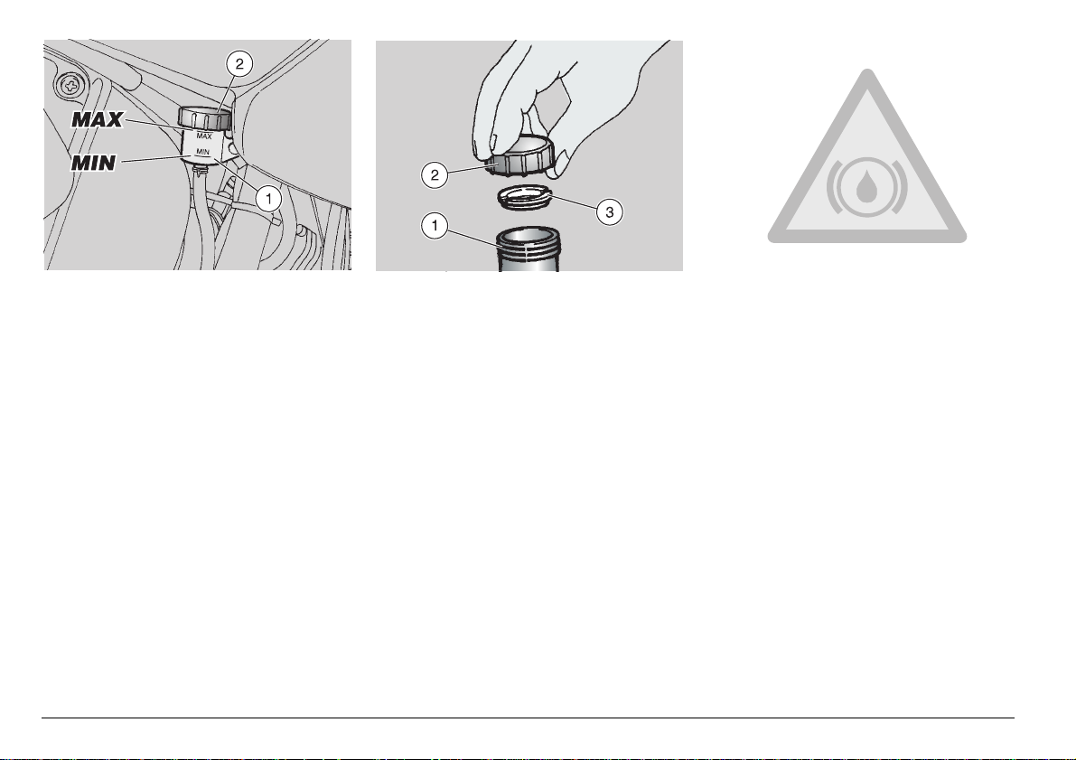
CHECKING
Position the vehicle on firm and
flat ground.
◆
Keep the vehicle in vertical position, so
that the fluid contained in the tank (1) is
parallel to the plug (2).
◆
Make sure that the fluid level exceeds
the " MIN " mark.
◆
If the fluid does not reach the " MIN "
mark, provide for topping up.
use and maintenance
24
ETX 125
TOPPING UP
The brake fluid may flow out of
the tank. Do not operate the rear
a
plug is loose or has been removed.
◆
id in the tank parallel to the tank rim (in
horizontal position).
brake lever if the brake fluid tank
Unscrew and remove the plug (2).
In order not to spill the brake flu-
c
id while topping up, keep the flu-
◆
Remove the gasket (3).
◆
By means of a syringe, top up the brake
fluid reservoir (1), see p. 72 (LUBRICANT CHART) until reaching the “ MAX ”
mark.
◆
To reassemble the components, follow
the reverse order.
Check the braking efficiency. If
necessary, contact your
a
Official Dealer .
In case of excessive stroke of the brake
lever, of excessive elasticity or in case
there is air in the circuit, contact your
aprilia
necessary to bleed the system.
Official Dealer , since it may be
aprilia
 Loading...