

Page 1

K
Service Source
StyleWriter 1200
Page 2

K
Service Source
Basics
StyleWriter 1200
Page 3
Basics Introduction - 1
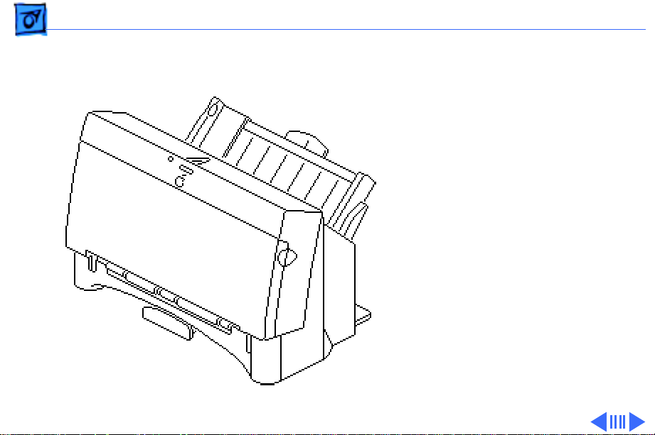
Introduction
The StyleWriter 1200 is a
high-resolution ink-jet
printer. There are some
differences between the
StyleWriter 1200 and the
StyleWriter II.
Page 4

Basics Introduction - 2
Hardware Differences
•The two out-feed rollers at the front of the printer have
only one rubber roller each, vs. two on StyleWriter II.
•The sheet feeder has changed to be compatible with the new
paper feeding scheme that the vendor has implemented
across the product line.
•The plastic cover of the controller and feed rollers has been
changed to match the paper feeder.
•The wheel on the carriage was removed.
Page 5

Basics Introduction - 3
Software Differences
•Some simplifications have been made to the controller
board, and the ROM has been upgraded to incorporate the
additional print modes, auto-power on/off, and a new selftest page.
• Two additional print modes have been added to the
StyleWriter 1200: Fine and Smooth. Fine mode uses 360 dpi
resolution and Smooth uses a 720 dpi horizontal by 360 dpi
vertical resolution.
• The printhead is automatically primed prior to the
printing of the self-test page.
• The Watermark feature allows the user to specify an image
to appear in the background of each page being printed.
Page 6

Basics Introduction - 4
Paper Sizes
The Executive size has been added to the StyleWriter 1200.
The printer offers four paper sizes:
• Letter (8.5" x 11")
• Legal (8.5" x 14")
• A4 (210 mm x 297 mm)
• Executive (7.25 mm x 10.5 mm)
Page 7

Basics Introduction - 5
Envelope Sizes
The number 6 envelope size has been added to the
StyleWriter 1200. The printer offers two envelope sizes:
• Number 6 (6.5" x 3.625")
• Number 10 (9.5" x 4.125")
Page 8
Basics Test Page - 6
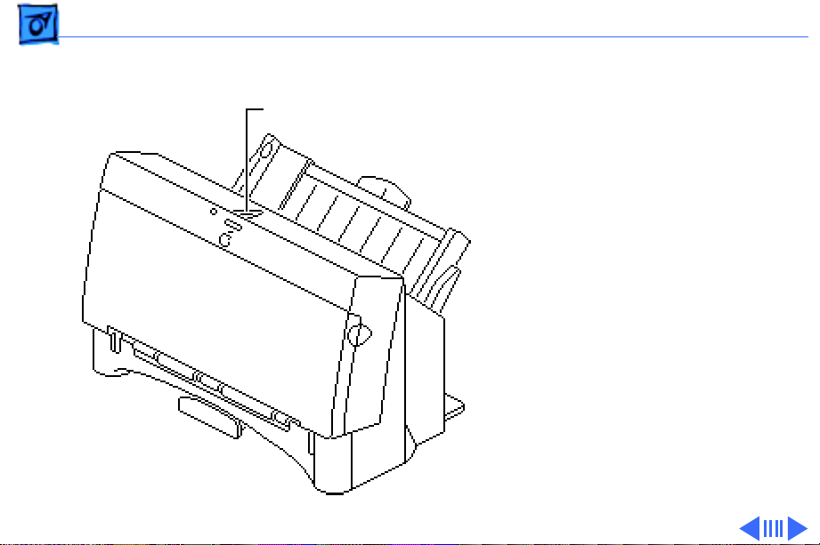
Test Page
Online Key
Turn on the printer and hold
down the online key for at
least 6 seconds or until the
test page prints.
Page 9
Basics Test Page - 7
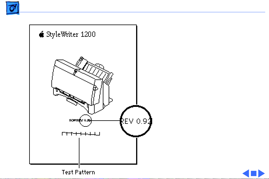
The test page shows the ROM
revision and a test pattern.
Use the test pattern to
determine if the ink jets are
functioning properly. If
lines appear broken,
proceed to the “Printing”
topic in the Troubleshooting
chapter.
Page 10

K
Service Source
Specifications
StyleWriter 1200
Page 11

Specifications Characteristics - 1
Characteristics
Print Methods
Print Head
Print Head Life
Serial bubble jet ink–on–demand
1 by 64 nozzles
Approximately 500 pages (normal mode)
Page 12

Specifications Graphics - 2
Graphics
Resolution
Best: 720 x 360 dpi (best mode, black and white, edge
smoothing)
360 x 360 dpi (grayscale)
Normal: 360 x 360 dpi
Draft: 180 x 180 dpi
Page 13

Specifications Paper Handling - 3
Paper Handling
Paper
Envelopes
Transparencies
Size: LTR, LGL, A4, Executive
Weight: 16–24 lb.
Capacity: 100 sheets (A4, LTR)
Size: Number 6 or 10
Capacity: 10 envelopes
Coated transparencies, or most inkjet transparencies
Page 14

Specifications Ink Cartridges - 4
Ink Cartridges
Type
Ink Color
Ink Amount
Life
Ink cartridge
Black
Approximately 28 g (per cartridge)
Approximately 500 pages
Page 15

Specifications Environmental - 5
Environmental
Acoustic Noise Level
Temperature
Humidity
Approximately 40 dB (reference level)
59–86°F (15–30°C)
10–80% (no condensation)
Page 16

Specifications Electrical - 6
Electrical
Power Source
Power Consumption
U.S./Japan: 120 VAC, 60 Hz, 1.0 A
Europe/Australia: 210–240 VAC, 50 Hz, 0.5 A
48 W maximum
Page 17

Specifications Physical - 7
Physical
Dimensions
Weight
Height: 7 in. (180 mm)
Width: 13.6 in. (345 mm)
Depth: 7.4 in. (200 mm)
Approximately 6.6 lb. (3 kg)
Page 18

K
Service Source
Troubleshooting
StyleWriter 1200
Page 19

Troubleshooting General/ - 1
General
The Symptom Charts included in this chapter will help you
diagnose specific symptoms related to your product. Because cures
are listed on the charts in the order of most likely solution, try
the first cure first. Verify whether or not the product continues to
exhibit the symptom. If the symptom persists, try the next cure.
(Note: If you have replaced a module, reinstall the original module
before you proceed to the next cure.)
If you are not sure what the problem is, or if the Symptom Charts
do not resolve the problem, refer to the Flowchart for the product
family.
For additional assistance, contact Apple Technical Support.
Page 20

Troubleshooting Symptom Charts /Preliminary Checks - 2
Symptom Charts
Preliminary Checks
Computer cannot find
printer
No lights or
movement
Print quality
problems
1 Verify that StyleWriter 1200 driver is installed.
2 Verify that Chooser and Control Panel settings are correct.
3 Verify that serial cable is connected.
4 Replace serial cable.
1 Verify that printer is turned on and plugged into wall socket.
2 Replace fuse.
1 Verify that paper is correct weight.
2 Purge ink cartridge.
3 Replace ink cartridge.
4 Replace printer.
Page 21

Troubleshooting Symptom Charts /Preliminary Checks - 3
Mechanical problems 1 Verify that paper is correct weight.
2 Clear paper jam.
3 Verify that cut sheet feeder aligns with printer.
4 Replace printer.
Page 22

Troubleshooting Symptom Charts /Status Light - 4
Status Light
No status lights 1 Replace fuse.
2 Verify that operation cable is securely connected to logic
board.
3 Replace printer.
Error light on 1 Printer is out of paper; add paper.
2 Check for paper jam; remove jam and then press power
switch.
3 Check for carriage jam.
4 Replace printer.
Page 23

Troubleshooting Symptom Charts /Printing - 5
Printing
No printing 1 Verify that interface cable between printer and computer is
tightly connected.
2 Make sure printer is selected in Chooser.
3 Purge ink cartridge.
4 Replace ink cartridge.
5 Verify that right-margin sensor is seated correctly.
6 Replace printer.
Garbled printing 1 Verify that interface cable between printer and computer is
tightly connected.
2 Purge ink cartridge.
3 Replace ink cartridge.
4 Replace printer.
Page 24

Troubleshooting Symptom Charts /Printing - 6
Overprinting 1 Verify that program being used is set for correct line
spacing and line length.
2 Verify that correct printer driver is installed.
3 Replace printer.
Image too light or too
dark
White lines in
printing
1 Purge ink cartridge.
2 Use 16Ð24 lb. cotton bond paper.
3 Verify that forms thickness lever is set correctly (up for
standard paper and down for envelopes, transparencies,
labels, and heavy paper).
4 Replace ink cartridge.
1 Purge ink cartridge.
2 Replace ink cartridge.
3 Replace printer.
Page 25

Troubleshooting Symptom Charts /Printing - 7
Page prints off
center; images are out
of place
Ink appears on back of
paper
Image wavy, splotchy,
or distorted
1 Use 16Ð24 lb. cotton bond paper.
2 Verify that sheet feeder holds no more than 50 sheets.
3 Verify that paper is inserted properly.
4 Verify that margins in document and paper size in Page Setup
are set correctly.
5 Replace printer.
1 Clean platen with soft, dry cloth.
2 Clean platen rollers.
3 Replace printer.
1 Purge ink cartridge.
2 Replace ink cartridge.
3 Replace printer.
Page 26

Troubleshooting Symptom Charts /Carrier Movement - 8
Carrier Movement
Erratic carrier
motion
Power light is on;
carrier does not move
Printer does not
perform self-test;
ready light is on
Carrier grinds, hums
loudly, or locks
Replace printer.
1 Make sure carrier area is clear of obstructions.
2 Replace printer.
Replace printer.
1 Verify that right-margin sensor is seated correctly.
2 Replace printer.
Page 27

Troubleshooting Symptom Charts/Paper Feed - 9
Paper Feed
No paper feed 1 Verify that cut sheet feeder aligns with printer.
2 Release paper pressure plate on cut sheet feeder.
3 Make sure paper path is clear of obstructions.
4 Replace printer.
Grinding during paper
feed
Paper feed
difficulties: binding,
tearing
1 Make sure paper path is clear of obstructions.
2 Verify that forms thickness lever is set correctly (up for
standard paper and down for envelopes, transparencies,
labels, and heavy paper).
3 Verify that cut sheet feeder aligns with printer.
4 Replace printer.
1 Verify that forms thickness lever is set correctly (up for
standard paper and down for envelopes, transparencies,
labels, and heavy paper).
2 Make sure paper path is clear of obstructions.
Page 28

Troubleshooting Symptom Charts /Paper Feed - 10
3 Verify that paper is inserted properly.
4 Use 16Ð24 lb. cotton bond paper.
5 Verify that cut sheet feeder aligns with printer.
6 Replace printer.
Envelope feed
problems
1 When printing envelopes: (a) adjust paper thickness lever;
(b) do not run cut sheets and envelopes in same print job;
(c) reset paper thickness lever when finished printing
envelopes.
2 Replace printer.
Page 29

Troubleshooting Symptom Charts /Miscellaneous - 11
Miscellaneous
Operations panel
buttons donÕt work
Software-specific
problem
1 Verify that operations panel cable is securely connected to
logic board and operations panel.
2 Replace printer.
1 Verify that software is known-good.
2 Verify that software is compatible with TrueType fonts.
(Check your software application manual.)
Page 30

K
Service Source
T ak e Apart
StyleWriter 1200
Page 31

Take Apart Covers - 1
Covers
No preliminary steps are
required before you begin
this procedure.
Caution:
precautions in Bulletins/
Safety.
Caution:
excessive force to release a
latch or tab.
Note:
the removal of all the covers
on the printer.
Review the ESD
Do not use
This procedure covers
Page 32

Take Apart Covers - 2
Front Access Cover
1
Note:
The front access
cover is held in place by
two arms that function
as hinges. Plastic tabs at
the end of the arms fit
into knobs on the inside
of the upper case.
Open the front access
Arm
Arm
cover.
2 Press the end of each
arm inward and free the
arm tabs from the
upper case.
Front Access Cover
3 Lift off the front access
cover.
Page 33

Take Apart Covers - 3
Upper Case
Upper Case
Release the right side latch
and lift the upper case a
short distance. Repeat for
the left side latch and
remove the case.
Latch
Page 34

Take Apart Covers - 4
Output T ray Assembly
Pull out the tray until the
two tabs rest against the
stops. Press down and
remove the tray.
0utput Tray
Page 35

Take Apart Covers - 5
Rear Cover
Rear Cover
Top Latch
Bottom Latch
1 Press out the two latches
on the bottom of the
printer and press up on
the rear cover.
2 Release the two latches
on the top of the printer.
3 Lift up and remove the
rear cover.
Page 36

Take Apart Covers - 6
Cut Sheet Feeder Cover
Cut Sheet Feeder
1 Press in the front latch
Side Latch
Front Latch
Front Latch
and release the side
latch.
2 Pull back and remove the
cover.
Page 37

Take Apart Covers - 7
Paper Support
Paper Support
1 Pull out the paper
support until it rests
against the stops.
2 Push the support
forward and disconnect
the latches.
3 Slide out the paper
support.
Page 38

Take Apart Covers - 8
Bottom Cover
1 Using a screwdriver,
push out the two front
latches.
2 Pull up and remove the
bottom cover.
Front
Latch
Bottom Cover
Front Latch
Page 39

Take Apart Covers - 9
Replacement Note:
sure the bottom cover
circular tabs are fit
into the proper position
in the printer frame.
Make
Page 40

Take Apart Covers - 10
Latch
On/Off Button
Replacement Note:
Make
sure the latch on the
upper case engages the
on/off button on the logic
board.
Page 41

Take Apart Cut Sheet Feeder - 11
Cut Sheet Feeder
Before you begin, remove
the covers.
Cut Sheet Feeder
Caution
precautions in Bulletins/
Safety.
Caution:
on your hands or clothes.
Although the ink is water
soluble, it contains dyes that
will stain.
: Review the ESD
Do not get the ink
Page 42

Take Apart Cut Sheet Feeder - 12
1 Using a Phillips
screwdriver, remove
the two screws that
secure the cut sheet
feeder to the printer.
2 Press in the latch and
remove the cut sheet
Alignment Pin
Latch
feeder.
3
Replacement Note:
sure the alignment pins
Make
on the cut sheet feeder
are aligned with the
printer frame.
Page 43

Take Apart Roller and Spring - 13
Roller and Spring
Before you begin, remove
the front cover.
Front Cover
Caution
precautions in Bulletins/
Safety.
: Review the ESD
Page 44

Take Apart Roller and Spring - 14
1 Push the roller forward
slightly.
2 Carefully lift up and
remove the roller and
spring.
Page 45

Take Apart Cut Sheet Feeder Roller - 15
Cut Sheet Feeder Roller
Before you begin, remove
the following:
• Covers
• Cut sheet feeder
Cut Sheet Feeder
Roller
Caution
precautions in Bulletins/
Safety.
: Review the ESD
Page 46

Take Apart Cut Sheet Feeder Roller - 16
1
Caution:
When the roller
is removed, the feeder
gear is loose. Remove the
roller slowly so that the
gear will not fly off.
Press in the two latches
on the cut sheet feeder
roller and push out the
roller.
2 Remove the gear.
3 Lift up on one end of the
roller and remove the
other end from the
mounting hole.
Roller
Page 47

Take Apart Cut Sheet Feeder Roller - 17
Line/Notch
Line/Notch
Replacement Note:
Align
the notch on the upper
gear with the upper line
on the cut sheet feeder.
Align the notch on the
lower gear with the
lower line on the cut
sheet feeder.
Page 48

Take Apart Carriage Assembly - 18
Carriage Assembly
Before you begin, remove
the following:
• Covers
• Cut sheet feeder
Carriage Assembly
Caution
precautions in Bulletins/
Safety.
Caution:
print nozzles from clogging,
do not touch or wipe them.
: Review the ESD
To prevent the
Page 49

Take Apart Carriage Assembly - 19
1 Disconnect connector
CNH from the logic
board.
Connector CNH
Page 50

Take Apart Carriage Assembly - 20
2 Remove the plastic
ribbon cable and cable
holder.
Replacement Note:
sure the ribbon cable
holes are mounted on the
two tabs on the inside of
the ribbon cable holder.
Make
Page 51

Take Apart Carriage Assembly - 21
3 Press in the two latches.
4 Push up and remove the
carriage release clip.
Carriage Release Clip
Latch
Latch
Page 52

Take Apart Carriage Assembly - 22
5 Carefully remove the
shaft clips from each
side of the carriage
assembly.
Shaft Clip
Page 53

Take Apart Carriage Assembly - 23
6 Move the carriage to the
far right and disconnect
the carriage from the
Carriage Guide
carriage guide.
Caution:
Do not remove
or loosen the two screws
on top of the carriage
guide. Loosening or
removing these screws
will cause the carriage
to go out of alignment.
Page 54

Take Apart Carriage Assembly - 24
7 Using a flat-blade
screwdriver, carefully
press in the idler roller
and disconnect the
carriage belt.
Page 55

Take Apart Carriage Assembly - 25
8 Hold the carriage
assembly and push back
the carriage shaft.
9 Slide out the carriage
shaft.
Page 56

Take Apart Carriage Motor - 26
Carriage Motor
Carriage
Motor
Before you begin, remove
the following:
• Covers
• Cut sheet feeder
Caution
precautions in Bulletins/
Safety.
: Review the ESD
Page 57

Take Apart Carriage Motor - 27
1 Disconnect connectors
CNH and CNCR from the
main board.
Connector
CNCR
Connector CNH
Page 58

Take Apart Carriage Motor - 28
2 Using a flat-blade
screwdriver, press in
the idler roller and
disconnect the carriage
belt.
Page 59

Take Apart Carriage Motor - 29
3 Using a Phillips
screwdriver, remove
the two mounting
screws.
4 Lift up and pull out the
carriage motor.
Page 60

Take Apart Eject Roller - 30
Eject Roller
Before you begin, remove
the covers.
Eject Roller
Caution
precautions in Bulletins/
Safety.
: Review the ESD
Page 61

Take Apart Eject Roller - 31
Grasp one end of the roller,
press it firmly to the side,
and snap the roller out of the
mounting holes.
Page 62

Take Apart Fuse - 32
Fuse
Before you begin, remove
the following:
• Covers
• Cut sheet feeder
Fuse
Caution
precautions in Bulletins/
Safety.
: Review the ESD
Page 63

Take Apart Fuse - 33
Remove the fuse cover and
replace the fuse.
Page 64

K
Service Source
Additional Procedures
StyleWriter 1200
Page 65

Additional Procedures Ink Cartridge Cleaning - 1
Ink Cartridge Cleaning
No preliminary steps are
required before you begin
this procedure.
Caution:
printer’s ink on your hands
or clothes. Although the ink
is water soluble, it contains
dyes that will stain.
Caution:
print nozzles from clogging,
do not touch or wipe them.
The print nozzles are on the
bottom of the ink cartridge.
Do not get the
To prevent the
Page 66

Additional Procedures Ink Cartridge Cleaning - 2
Note:
Use the Cleaning
option to correct blurred
characters, horizontal white
streaks, and missing dots
caused by clogged ink
nozzles.
Page 67

Additional Procedures Ink Cartridge Cleaning - 3
1 Make sure the
StyleWriter 1200
printing software is
installed.
2 Using the Chooser, select
StyleWriter 1200.
3 Make sure the correct
printer port is selected.
4 Close the Chooser.
Page 68

Additional Procedures Ink Cartridge Cleaning - 4
5 Open any document and
select the print option or
choose Print Window
from the File menu.
Page 69

Additional Procedures Ink Cartridge Cleaning - 5
6 Click the Options button
in the Print dialog box.
Page 70

Additional Procedures Ink Cartridge Cleaning - 6
7 Select the “Clean ink
cartridge before
printing” option and
click OK.
Page 71

K
Service Source
Exploded V ie w
StyleWriter 1200
Page 72

Exploded View 1
Whole Unit
110V 661-0242
220V 661-0243
Rear Cover
922-0184
Front Cover
Spring
922-0190
Front Cover
922-1290
Carriage
Motor
922-0195
Eject Roller
922-0191
Carriage Belt
922-0193
Carriage Unit
922-1291
Chassis*
Interface Cover
922-1928
Upper Case
Cover
922-0185
Cut Sheet
Feeder
922-0188
Paper
Support
922-0189
Cut Sheet
Feeder
Roller
922-0192
Cover, Logic Board
922-2061
Logic Board*
Carriage Release Clips
922-0197
Clip, Shaft
922-0196
Fuse
125 V 922-0180
250 V 922-0181
Feet, Bottom
922-0182
Output Tray
922-0187
*Part of Whole Unit
Power Supply*
BottomCase
922-0198
 Loading...