

Page 1
K
Service Source
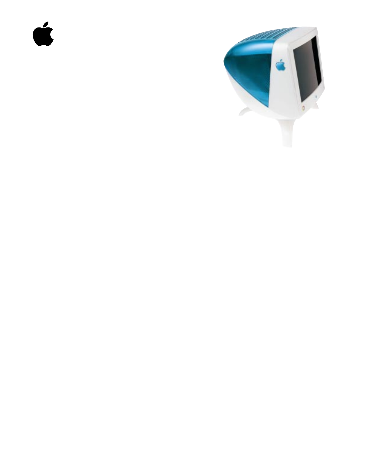
Studio Display (21" CRT, 19.8"
viewable image size)
Page 2
K
Service Source
Basics
Studio Display (21" CRT, 19.8"
viewable image size)
Page 3
Basics Overview - 1
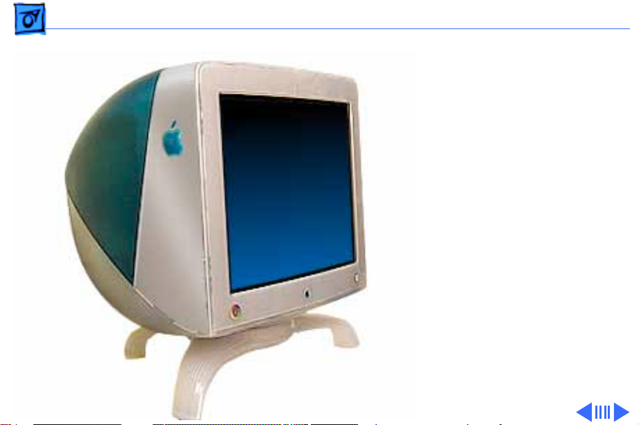
Overview
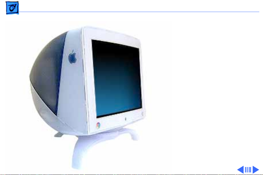
The Studio Display (21"
CRT, 19.8" viewable image
size) supports screen
resolutions ranging from
640 x 480 at 60 Hz to 1600
x 1200 at 85 Hz.
The Studio Display (21"
CRT) complies with TCO 99
as certified by the Swedish
Confederation of
Professional Employees to
meet global safety tests and
energy-saving features.
Page 4

Basics Overview - 2
Features
Features of the Studio Display (21" CRT) include
• 21-inch (19.8-inch diagonal viewable image size) Sony
Trinitron CRT
• 0.25/0.27 mm variable aperture grille pitch
• four USB ports for high-speed USB devices
• horizontal scan rate of 31.5–106 kHz
• multiple resolutions
• translucent plastic housing and tripod stand
• user controls for brightness, contrast, and the Monitors
& Sound control panel
• compatibility with USB-based, 1999-model Power
Macintosh G3 or Power Mac G4 computers (refer to
“Extended Compatibility for Service” in this chapter for
more details on compatibility)
• Energy Star compliance
Page 5
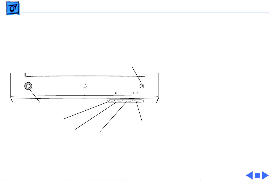
Basics Overview - 3
The front panel of the
display includes the
following controls:
• power button
• brightness increase and
Power Button
decrease
• contrast increase and
decrease
• control panel launcher
button
Control Panel Launcher Button
The control panel launcher
Contrast Decrease Button
Contrast Increase Button
Brightness Increase Button
Brightness Decrease Button
button opens the Monitors &
Sound control panel window.
Page 6

Basics Repair Issues - 4
Repair Issues
Caution:
weighs 77 pounds (35 kg). Use caution when lifting or
moving the display. To move it, lift it by the hand grips on
the bottom of the display. It is recommended that two people
lift the monitor together.
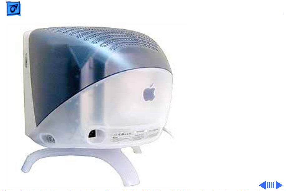
The new exterior design features of this display include a
two-color translucent housing, a tripod monitor stand, and a
VGA-style video cable with a VGA-to-Macintosh adapter.
Out of the box, the Studio Display (21" CRT)
Page 7

Basics Repair Issues - 5
Protecting the Translucent Housing
Important:
translucent plastic, surface scratches can be more visible
than on a standard plastic housing. To avoid cosmetic damage
and protect the housing during service procedures, please
keep in mind the following precautions:
• Use a protective pad that is clean and free of debris
whenever you service the display.
• Use caution working with metal tools to avoid scratching
the housing.
• Before placing the display face down on a book or ream of
paper, ensure the surface provides protection from
scratches.
Because the housing of this monitor is made of
Page 8

Basics Repair Issues - 6
New Tripod Stand Safety Tips
Because this is a new design, keep in mind the following:
•
Caution:
and right sides of the display. Never lift the display by
the tripod stand.
•
Caution:
pushing or pulling the stand legs. The tripod stand is
subject to cracking or breakage if mishandled.
±
•
surface, ensure that all three legs on the tripod stand
contact the surface. If one of the legs is too close to the
table edge, the weight of the monitor could cause the
display to fall off the edge.
Lift the display by the hand grips under the left
Do not adjust the position of the monitor by
Warning:
When placing the monitor on a table
Page 9
Basics Repair Issues - 7
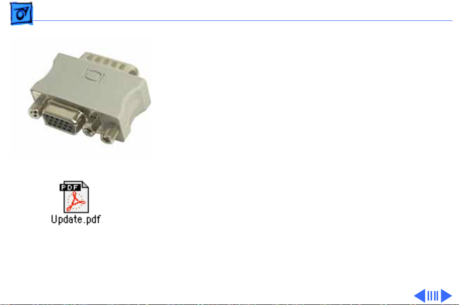
VGA-to-Macintosh Adapter
The connector on the display cable is a VGA video connector.
To ensure the proper connection to your computer or video
card, click the icon Update.pdf for instructions on using the
VGA-to-Macintosh adapter that comes with the Studio
Display (21" CRT).
Page 10
Basics Repair Issues - 8
Extended Compatibility for Service
This Studio Display (21" CRT) works with USB-based,
1999-model Power Macintosh G3 or Power Mac G4
computers. These configurations are still the only approved
configurations for customers using this display. However,
Apple-authorized service providers may service the display
using the following PCI-based Power Macintosh computers,
running Mac OS 8.5 or later, with a third-party Keyspan
USB card installed in the PCI slot:
• Power Macintosh 4400
Find out about the Keyspan
USB card at:
http://www.keyspan.com
• Power Macintosh 6500
• Power Macintosh 7200
• Power Macintosh 7250
• Power Macintosh 7300
• Power Macintosh 7350
• Power Macintosh 8500
• Power Macintosh 8550
Page 11

Basics Repair Issues - 9
• Power Macintosh 8600
• Power Macintosh 9600
• Power Macintosh 9650
To properly set up the display to work with one of the listed
Power Macintosh computers, follow these steps:
1 Confirm that the computer has at least 2 MB VRAM
(required to enable all screen resolutions).
2 Install the Keyspan USB card in the PCI expansion slot.
3 Perform a clean install with Mac OS 8.5 or later.
4
Important:
screen, open the Energy Saver control panel and set the
system sleep mode to Never.
5 Install USB driver 1.1 or later (called Mac Installer)
from the disc that comes with the Keyspan USB card.
To avoid a system “freeze” with a blank
Page 12

Basics Repair Issues - 10
6 Install Apple Displays Software 1.7.1 or later.
7 Restart system and verify that USB ports are working.
Page 13

Basics Repair Issues - 11
USB Display Service Utility, version 2.1.2
In February 2000 version 2.1.2 of the USB Display Service
Utility was introduced. The main difference between this
version and earlier versions is the addition of PowerBook
(FireWire) compatibility.
Important:
Service Utility. To avoid loss of data, use only the latest
version of the USB DSU. Refer to the Read Me file for more
information. You can access the Read Me file and the latest
version of the USB Display Service Utility from the Service
Diagnostics page from Service Source Online.
±
Warning:
download setup parameters, refer to “When the Second
Display is a PowerBook (FireWire)” in the Adjustments
chapter. You must follow that procedure to avoid loss of data
or functionality.
Destroy previous versions of the USB Display
If you plan to use a PowerBook (FireWire) to
Page 14

Basics Repair Issues - 12
Apple Displays Software, version 1.8
In August 1999 version 1.8 of the Apple Displays Software
was released. One of the main differences from previous
versions (1.7.1 and earlier) is the name of a control panel.
The Monitors & Sound control panel (in versions 1.7.1 and
earlier), used for some screen adjustments, is now called
the Monitors control panel in version 1.8 and later. The
features of the Monitors control panel are the same as the old
Monitors & Sound control panel, except audio controls now
have their own separate Sound control panel.
References in this manual that previously specified the
Monitors & Sound control panel, now specify the Monitors
control panel.
Page 15
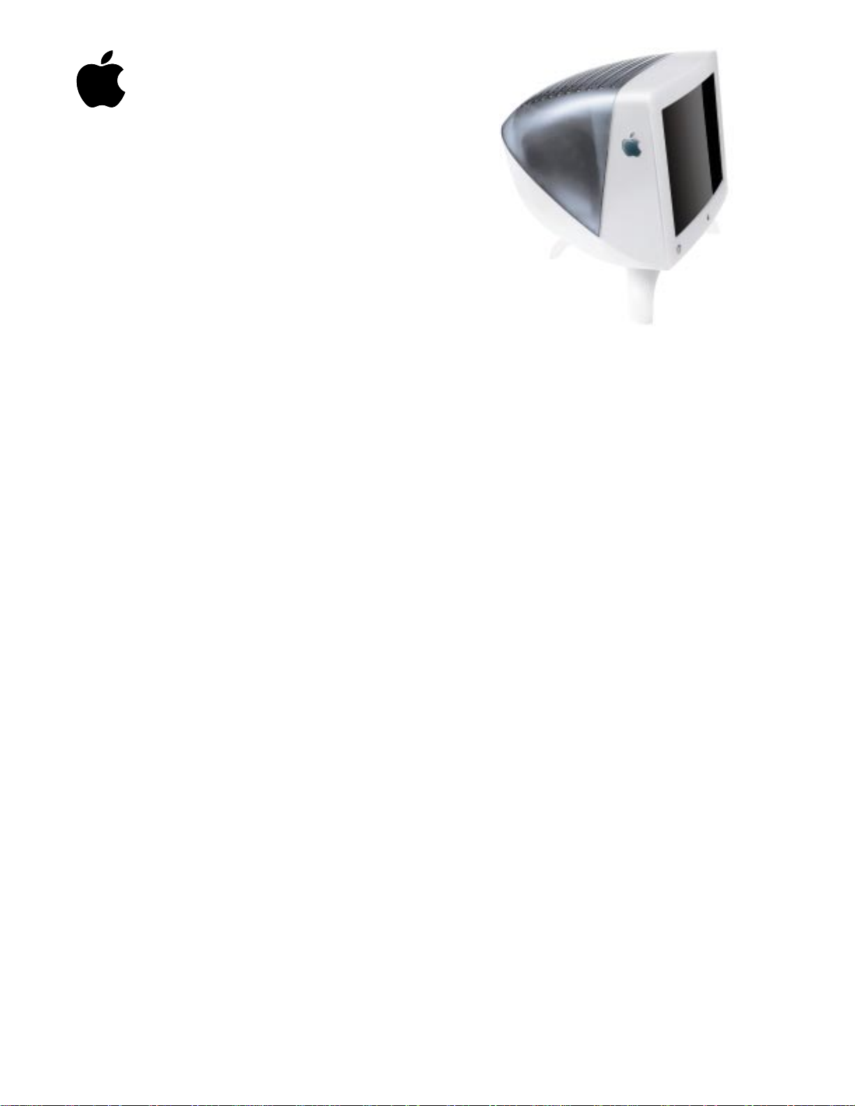
Basics Repair Issues - 13
New Housing Color
In August 1999, a new
version of the Studio Display
(21" CRT) was introduced.
The display performance and
internal circuitry remains
the same as the original
version. However, the new
version offers a new housing
color.
Page 16
Basics Repair Issues - 14
Unlike the original colors of
translucent blue and white,
the new version of the
display is translucent
graphite and white.
Important:
parts (rear housing, bottom
housing with colored control
panel buttons, intermediate
bezel, front bezel, product
ID label, and USB label)
should be exchanged like for
like.
The following table shows
the Apple part numbers for
the housing parts that differ
The housing
Page 17
Basics Repair Issues - 15
by color. Finished goods number M6204LL/A represents the
original blue and white version; M6204LL/B represents
the new graphite and white version.
Part Name M6204LL/A M6204LL/B
Rear housing 922-3681 922-3914
Bottom housing 922-3723 922-3917
Intermed. bezel 922-3726 922-3916
Front bezel 922-3725 922-3913
Product ID label 922-3756 922-3918
USB label 922-3757 922-4055
In addition, a button panel kit (076-0805) contains one of
each color of the button control panel (brightness and
contrast buttons).
Page 18
Basics Repair Issues - 16
New Version of CRT/Video Board
In November 1999, a new version of the CRT/video board
was released. The new version was necessary to handle a
discontinuation of a board component. Adding a different
manufacturer’s component required a somewhat different
board layout.
Important:
not backward compatible with Version 1 (Apple part
number 661-2116). Before replacing a CRT/video board,
you must verify its version and exchange boards like for
like.
For details on identifying the two boards, refer to the section
“Two Versions of the CRT/Video Board” in the
Troubleshooting chapter.
Version 2 (Apple part number 661-2231) is
Page 19

Basics U.S. Repair Strategy - 17
U.S. Repair Strategy
The Studio Display (21" CRT) can be serviced by AppleAuthorized Service Providers (AASPs). For those repairs
that cannot be performed by the AASP (such as CRT repair/
replacement), the service facilitation process is in place.
Parts
To order replacement parts, use the AppleOrder system and
refer to Studio Display (21" CRT) in the “Service Price
Pages.” Large businesses, universities, and K-12 accounts
must provide a purchase order on all transactions, including
orders placed through the AppleOrder system.
Service providers not enrolled in AppleOrder may fax their
orders to Service Provider Support (512-908-8125) or
mail them to the following address:
Page 20

Basics U.S. Repair Strategy - 18
Apple Computer, Inc.
Service Provider Support
Mail Stop 212-SPS
2323 Ridgepoint Drive
Austin, TX 78754
Ordering
Apple Service Providers planning to support the Studio
Display (21" CRT) may facilitate service by calling 800919-2775.
For more details on this facilitation process, please refer to
the Facilitation Process in the archived service notices
section of the Service Source CD. (Open the Notices Archive
folder at the top level of the Main CD. The complete path is
Notices Archive: Service Notices Archive: Service Source
Startup: Service Information: Notices: Service Notices:
Archived List: Facilitation Process.)
Page 21

Basics U.S. Repair Strategy - 19
If you have further questions, please call Service Provider
Support at 800-919-2775 and select option 1.
Warranty and AppleCare Protection Plan
The Studio Display (21" CRT) is covered under the Apple
One-Year Limited Warranty. The AppleCare Protection Plan
is also available for this product. Service Providers are
reimbursed for warranty and AppleCare Protection Plan
repairs facilitated for this display. For pricing information,
refer to “Service Price Pages.”
Page 22

Basics Canada Repair Strategy - 20
Canada Repair Strategy
The service strategy for the Studio Display (21" CRT) is
module replacement. However, sometimes replacing modules
may not resolve the issue. For those issues, whole-unit
replacements are available. To limit “no fault found”
returns on the unit, please use the following procedure when
you require a whole-unit replacement:
1 Troubleshoot the unit to ensure the problem is not with
the software or with the computer.
2 After confirming the issue is with the display, refer to
Service Source Online or the Service Price Pages to
order the modules necessary to repair the display.
3 If the module necessary is not available, or you require a
whole-unit replacement, call Technical Service
Provider Support (TSPS) at 1-800-217-9517. Have
Page 23
Basics Canada Repair Strategy - 21
your 10-digit service account number (beginning with
61) ready. Be prepared to explain the issue, your
troubleshooting steps, and the display's serial number to
the TSPS phone agent.
4 After verifying the troubleshooting you've performed,
the TSPS phone agent will authorize the repair by giving
you the whole-unit service replacement part number,
and a Vantive case number.
5 Use AppleOrder to place the order for the whole-unit
service replacement by manually populating the Part
Number field with the part number given to you by the
TSPS. Then mark the order for review, and put the
Vantive case number in the Comments field. Failure to do
so will result in your order being declined.
6 When you receive the whole-unit service replacement,
return the old display as you would any service module.
Page 24
K
Service Source
Specifications
Studio Display (21" CRT, 19.8"
viewable image size)
Page 25

Specifications Introduction - 1
Introduction
Specifications information for the Studio Display (21" CRT) can
be found in the Spec Database, which you can access in one of three
ways:
• Launch it directly by double-clicking the Apple Spec Database
runtime alias at the top level of the Main Service Source CD.
• Select “Apple Spec Database” from the Service Source dropdown main menu.
• Click the Acrobat toolbar icon for the database, which is near
the right end of the toolbar with the letters “SP.”
Page 26
Features
Exceptional display quality
• 21-inch (19.8-inch viewable image size) Sony
Trinitron CRT
• Aperture grille technology for vivid colors and
sharp text
• Vertically flat screen for reduced glare
Stunning design
• Elegant translucent case that matches Apple’s latest
Power Macintosh G3 computers
• Storage space under the display for your keyboard
• Four-port USB hub for connecting peripherals
Built-in color calibration
• Uses industry-standard ColorSync color
management technology
• Ensures consistent, accurate color over the lifetime
of the monitor
• Saves production time by creating accurate output
with fewer trials
Easy access to powerful software controls
• Single-button access to the familiar Macintosh
Monitors & Sound control panel
• Intuitive control over all screen adjustments
Color is indispensable to today’s computer applications, whether you’re producing magazines,
creating business presentations, or designing multimedia materials.
The Apple Studio Display with ColorSync technology is an uncompromising monitor that
provides accurate color for every situation. It combines lifetime color calibration with outstanding visual performance and a stunning appearance—all for little more than competitive
monitors without those features.
The first thing you’ll notice about this Apple Studio Display is its striking appearance. Its elegant
translucent enclosure and sleek design complements Apple’s newest Power Macintosh G3
systems and is also highly functional. It includes a four-port Universal Serial Bus (USB) hub, and
its unique stand has room underneath to store your keyboard.
The Apple Studio Display with ColorSync technology uses a 21-inch (19.8-inch viewable image
size) Trinitron CRT to deliver vivid colors and sharp text. The cylindrical design of this CRT
creates a vertically flat screen that minimizes glare. The end result is a monitor that’s a pleasure
to view and to work with.
But the most important feature of the Apple Studio Display with ColorSync technology is its
superior color accuracy—and its ability to maintain that accuracy over its lifetime. Using a
patented internal measurement system, the monitor adjusts its electron beam as time passes to
maintain the precise calibrations made at the factory. It can also compensate for changes in the
ambient light. And because it stores its own ColorSync profiles, it can exchange accurate color
information with the other devices in your production process, creating color consistency that
directly translates into fewer trial-and-error stages when you output color documents.
The Apple Studio Display makes it easy to meet your specific needs and to compensate for
changes in environmental conditions. A button on the display brings up the familiar Macintosh
Monitors & Sound control panel on your computer, giving you powerful yet intuitive software
control over all screen adjustments.
With its large screen, crisp Trinitron performance, ready-to-use USB ports, built-in color
calibration, and elegant design, the Apple Studio Display with ColorSync technology is the
complete monitor for demanding applications.
Apple Studio Display with
ColorSync Technology
Page 27
2
Ordering Information
Apple Studio Display with
ColorSync technology
Order No. M6204LL/A
• Apple Displays software
• VGA-to-Macintosh adapter
• Power cord
• Ambient light tool
• User’s setup guide
• Limited warranty
For More Information
For more information about this product, or to find out
where to buy Apple products, visit www.apple.com
on the World Wide Web or call 1-800-538-9696.
To purchase this product from the Apple Store, go
to www.apple.com/store.
Apple stands behind its products with world-class
service and support. Offering quality parts, extended
hardware service options, phone support, and support
via the Internet, we provide you with support choices
that meet your needs. For more information, visit
www.apple.com/support.
Technical Specifications
Picture tube
• 21-inch (diagonal) Trinitron CRT
• 19.8-inch (diagonal) viewable image size
• Variable, superfine 0.25- to 0.27-mm aperture
grille pitch
Resolutions and refresh rates*
• 640 by 480 pixels at up to 85 Hz
• 800 by 600 pixels at up to 85 Hz
• 832 by 624 pixels at up to 75 Hz
• 1,024 by 768 pixels at up to 85 Hz
• 1,152 by 870 pixels at up to 75 Hz
• 1,280 by 1,024 pixels at up to 85 Hz
• 1,600 by 1,200 pixels at up to 85 Hz
Scanning rates
• 31 to 107 kHz (horizontal)
• 48 to 120 Hz (vertical)
User controls (hardware and software)
• Power on/off
• Brightness
• Contrast
• Horizontal size and centering
• Vertical size and centering
• Convergence
• Rotation
• Pincushion
• Keystone
• Parallelogram
• Bow
• Geometry corner correction
• Separate four-corner beam landing correction
• Overscan
• Degauss
Color controls
• Internal calibration system
• Gamma curve adjustment
• Completely variable white-point selection
(4,100K to 9,300K)
• Designed for optimal reproduction of PANTONE colors
Screen treatment
• High-contrast, antireflective, antistatic coating
Connectors and cables
• 15-pin mini D-Sub VGA connector
• VGA-to-Macintosh adapter
• Four-port USB hub
Electrical requirements
• Line voltage: 90V to 264V AC
• Frequency: 47 to 63 Hz, single phase
• Power: 180W (maximum) when operating; less than
30W in standby mode; less than 5W when computer
is in energy-saver mode
Agency approvals
• MPR II
• CE Mark
• EPA ENERGY STAR compliant
• IEC 950
• UL1950
• CSA 950
• EN60950
• NUTEK
• TCO 99
• FCC Part 15 Class B; DOC Class B
Environmental requirements
• Operating temperature: 50° to 104° F (10° to 40° C)
• Storage temperature: 32° to 140° F (0° to 60° C)
• Operating humidity: 20% to 95% noncondensing
• Storage humidity: 5% to 95% noncondensing
• Operating altitude: 0 to 10,000 feet (0 to 3,048 m)
Size and weight
• Height: 22.3 inches (56.6 cm)
• Width: 20.1 inches (51.1 cm)
• Depth: 21.7 inches (55.0 cm)
• Weight: 77 pounds (35 kg)
System requirements
• The new Power Macintosh G3 computer with
built-in USB
• Mac OS 8.0 or later
* Not all computer models and configurations are capable of driving the
monitor to the highest display format it supports.
Specification Sheet
Apple Studio Display with ColorSync Technology
Apple Computer, Inc.
1 Infinite Loop
Cupertino, CA 95014
(408) 996-1010
www.apple.com
© 1999 Apple Computer, Inc. All rights reserved. Apple, the Apple logo, ColorSync, Mac, Macintosh, and Power Macintosh are trademarks of Apple
Computer, Inc., registered in the U.S. and other countries. The Apple Store is a trademark of Apple Computer, Inc. PANTONE is a registered trademark of
Pantone, Inc. Trinitron is a trademark of Sony Corporation, registered in the U.S. and other countries. Other product and company names mentioned herein
may be trademarks of their respective companies. Mention of non-Apple products is for informational purposes only and constitutes neither an endorsement
nor a recommendation. Apple assumes no responsibility with regard to the selection, performance, or use of these products. All understandings, agreements,
or warranties, if any, take place directly between the vendors and the prospective users. Product specifications are subject to change without notice.
January 1999 L03536B
Nothing works and looks better with a new Power Macintosh
G3 computer than an Apple Studio Display with ColorSync
technology (sold separately).
Page 28
Features
Exceptional display quality
• 21-inch (19.8-inch viewable image size) Sony
Trinitron CRT
• Aperture grille technology for vivid colors and
sharp text
• Vertically flat screen for reduced glare
Stunning design
• Elegant translucent case that matches Apple’s new
Power Mac G4 computers
• Storage space under the display for your keyboard
• Four-port USB hub for connecting peripherals
Built-in color calibration
• Uses industry-standard ColorSync color
management technology
• Ensures consistent,accurate color over the lifetime
of the monitor
• Saves production time by creating accurate output
with fewer trials
Easy access to powerful software controls
• Single-button access to the familiar Macintosh
Monitors & Sound control panel
• Intuitive control over all screen adjustments
Color is indispensable to today’s computer applications, whether you’re producing magazines,
creating business presentations, or designing multimedia materials.
The Apple Studio Display with ColorSync technology is an uncompromising monitor that
provides accurate color for every situation. It combines lifetime color calibration with outstanding visual performance and a stunning appearance—all at a competitive price.
The first thing you’ll notice about this Apple Studio Display is its striking appearance. Its elegant
translucent enclosure and sleek design complement Apple’s new Power Mac G4 systems and
are also highly functional. The display includes a four-port Universal Serial Bus (USB) hub, and
its unique stand has room underneath to store your keyboard.
The Apple Studio Display with ColorSync technology uses a 21-inch (19.8-inch viewable image
size) Trinitron CRT to deliver vivid colors and sharp text. The cylindrical design of this CRT
creates a vertically flat screen that minimizes glare. The end result is a monitor that’s a pleasure
to view and to work with.
But the most important feature of the Apple Studio Display with ColorSync technology is its
superior color accuracy—and its ability to maintain that accuracy over its lifetime. Using a
patented internal measurement system, the monitor adjusts its electron beam as time passes to
maintain the precise calibrations made at the factory. It can also compensate for changes in the
ambient light. And because it stores its own ColorSync profiles, it can exchange accurate color
information with the other devices in your production process, creating color consistency that
directly translates into fewer trial-and-error stages when you output color documents.
The Apple Studio Display makes it easy to meet your specific needs and to compensate for
changes in environmental conditions. A button on the display brings up the familiar Macintosh
Monitors & Sound control panel on your computer, giving you powerful yet intuitive software
control over all screen adjustments.
With its large screen, crisp Trinitron performance, ready-to-use USB ports, built-in color
calibration, and elegant design, the Apple Studio Display with ColorSync technology is the
complete monitor for demanding applications.
Ap ple Stu dio Displa y with
ColorS ync Technology
Page 29
2
Ordering Information
Apple Studio Display with
ColorSync technology
Order No. M6204LL/B
• Apple Displays software
• Power cord
• Ambient light tool
• User’s setup guide
For More Information
For more information about this product, or
to find out where to buy Apple products, visit
www.apple.com/products on the World Wide
Web or call 800-538-9696.To purchase
this product from the Apple Store,go to
www.apple.com/store.
Apple stands behind its products with worldclass service and support. Offering quality parts,
extended hardware service options, phone support,
and support via the Internet, we provide you with
support choices that meet your needs. For more
information, visit www.apple.com/support.
Technical Specifications
Picture tube
• 21-inch (diagonal) Trinitron CRT
• 19.8-inch (diagonal) viewable image size
• Variable,superfine 0.25- to 0.27-mm aperture
grille pitch
Resolutions and refresh rates
• 640 by 480 pixels at up to 85 Hz
• 800 by 600 pixels at up to 85 Hz
• 832 by 624 pixels at up to 75 Hz
• 1,024 by 768 pixels at up to 85 Hz
• 1,152 by 870 pixels at up to 75 Hz
• 1,280 by 1,024 pixels at up to 85 Hz
• 1,600 by 1,200 pixels at up to 85 Hz
Scanning rates
• 31 to 107 kHz (horizontal)
• 48 to 120 Hz (vertical)
User controls (hardware and software)
• Power on/off
• Brightness
• Contrast
• Horizontal size and centering
• Vertical size and centering
• Convergence
• Rotation
• Pincushion
• Keystone
• Parallelogram
• Bow
• Geometry corner correction
• Separate four-corner beam landing correction
• Overscan
• Degauss
Color controls
• Internal calibration system
• Gamma curve adjustment
• Completely variable white-point selection
(4,100K to 9,300K)
• Designed for optimal reproduction of PANTONE colors
Screen treatment
• High-contrast,antireflective, antistatic coating
Connectors and cables
• 15-pin mini D-Sub VGA connector
• Four-port USB hub
Electrical requirements
• Line voltage:90V to 264V AC
• Frequency: 47 to 63 Hz, single phase
• Power:180W (maximum) when operating; less than
30W in standby mode; less than 5W when computer
is in energy-saver mode
Agency approvals
• MPR II
• CE Mark
• EPA ENERGY STAR compliant
• IEC 950
• UL1950
• CSA 950
• EN60950
• NUTEK
• TCO 99
• FCC Part 15 Class B; DOC Class B
Environmental requirements
• Operating temperature:50° to 104° F (10° to 40° C)
• Storage temperature:32° to 140° F (0° to 60° C)
• Operating humidity:20% to 95% noncondensing
• Storage humidity:5% to 95% noncondensing
• Operating altitude:0 to 10,000 feet (0 to 3,048 m)
Size and weight
• Height:22.4 inches (56.9 cm)
• Width:22.6 inches (57.4 cm)
• Depth:21.7 inches (55.0 cm)
• Weight:77 pounds (35 kg)
System requirements
• A 1999-model Power Macintosh G3 computer or a
Power Mac G4 computer with built-in USB
• Mac OS 8.5 or later
Specification Sheet
Apple Studio Display with ColorSync Technology
Apple Computer, Inc.
1 Infinite Loop
Cupertino, CA 95014
408-996-1010
www.apple.com
© 1999 Apple Computer, Inc. All rights reserved.Apple, the Apple logo, ColorSync, Mac, Macintosh, and Power Macintosh are trademarks of Apple
Computer,Inc., registered in the U.S. and other countries. The Apple Store and Power Mac are trademarks of Apple Computer, Inc. ENERGY STAR is a U.S.
registered mark. PANTONE is a registered trademark of Pantone, Inc. Trinitron is a trademark of Sony Corporation, registered in the U.S. and other
countries. Other product and company names mentioned herein may be trademarks of their respective companies. Product specifications are subject to
change without notice.
August 1999 L04180A
Nothing works and looks better with a new Power Mac G4
computer than an Apple Studio Display with ColorSync
technology (sold separately).
Page 30
K
Service Source
Troubleshooting
Studio Display (21" CRT, 19.8"
viewable image size)
Page 31

Troubleshooting General - 1
General
The “Symptom Charts” section included in this chapter will help
you diagnose specific symptoms related to your product. Because
cures are listed on the charts in the order of most likely solution,
try the first cure first. Verify whether or not the product
continues to exhibit the symptom. If the symptom persists, try
the next cure.
original module before you proceed to the next cure.
If you are not sure what the problem is, or if the symptom charts
do not resolve the problem, contact Apple Technical Support.
Note:
If you have replaced a module, reinstall the
Page 32

Troubleshooting First Checklist - 2
First Checklist
Important:
unnecessary time delays, read this checklist before you return a
module.
To prevent needless module replacement and
The display is not compatible with all
computers.
This Studio Display (21" CRT) works with USB-based, 1999model Power Macintosh G3 or Power Mac G4 computers. Refer to
“Extended Service Compatibility” in the Basics chapter for more
details on compatibility.
For best display performance, operate the display in one of the
factory-preset screen resolutions.
The CRT raster will not always resemble a
perfect rectangle.
CRT tolerances allow for some distortion. Additional distortion can
be caused by magnetized metal objects (desks, file cabinets).
Rotate the monitor or move it to a different location if you notice
raster bowing or bent raster edges. You can also use the Monitors
control panel or the USB Display Service Utility to make geometry
adjustments to optimize the screen display.
Jitter, faint lines, or screen movement can be
caused by the computer or external
interference such as electronic devices and
fluorescent lights.
Fluorescent lights, computers, other monitors, or electronic
appliances such as coffee makers and copy machines can cause
raster distortion. Move the unit to another room or building to
determine if external interference is the source of the problem.
Note:
If the raster has shifted up/down or right/left only, adjust
it using the geometry controls in the Monitors control panel
(Apple Displays Software). Keep in mind that if you then move the
monitor to another location you may need to readjust the controls.
If the display changes (for better or worse) when you move it to
another location, the environment is the source of the problem.
Move the monitor or the distortion-causing object.
Page 33

Troubleshooting First Checklist - 3
Variances in screen color and brightness are usually
caused by the setup controls or the environment.
Screen color purity over the entire screen may not always be
perfect. CRT tolerances allow for some distortion.
Try adjusting the beam landing, rotation, brightness, or contrast
to reduce or eliminate the symptom.
Color imperfections can be caused by magnetized metal objects
(desks, file cabinets). Move the unit to a different location if you
notice color blotches or a change in brightness on an area of the
screen. If the display changes (for better or worse) when you
move it to another location, the environment is the source of the
problem. Relocate the monitor or move the distortion-causing
object.
A misadjusted screen can mimic the
symptoms of main deflection board or CRT
failures.
By performing the adjustment procedures, you might determine if
one or more of the adjustments is the cause of the problem.
Page 34

Troubleshooting Symptom Charts - 4
Symptom Charts
Note:
Check this section periodically for updates and new
symptoms and cures.
No video (screen is
black); power
indicator light off
Important:
turned on, allow the monitor to warm up for approximately 30
minutes, unless instructed otherwise.
For procedures that require the monitor to be
No Video
1 Shut down computer and monitor. Inspect power cord for
damage; use ohmmeter to check for continuity.
2 Verify that monitor power cord is connected to power socket
on back of computer, that computer is connected to live power
source, that monitor power button is on, and that computer
connected to display is on.
3 Check for blown fuse (located at FP1) on power board. If
blown, replace it with 4 A, 250 V fuse (Apple part number
922-0502). Turn on power. If fuse blows again, replace
power board. If fuse blows again, it is likely that an
electrical short on the main deflection board is causing the
blown fuse. In this case, reinstall original power board (with
a new fuse), and replace main deflection board. Then follow
the steps in “Adjusting the Display after Replacing the Main
Deflection Board” in the Adjustments chapter.
4 Check for loose connections at user controls (control panel)
board. Reseat board and connectors.
5 Replace user controls (control panel) board.
No video (screen is
black); amber power
indicator light on
1 Check cable connections.
Important: Check for bent pins on the video connector. Be
sure the USB and video cables from the monitor are connected
to the ports on the computer.
2 Verify computer video signal by connecting known-good
monitor.
3 Check internal cable connections to CRT/video board.
4 Replace main deflection board, and follow the steps in
“Adjusting the Display after Replacing the Main Deflection
Board” in the Adjustments chapter.
5 Replace power board.
6 Replace video cable.
7 If the symptom remains, follow the steps in “Connecting a
Second Monitor for Downloading Setup Parameters” in the
Adjustments chapter. Then follow the steps in “Downloading
Setup Parameters and Replacing the CRT/Video Board” and
Page 35

Troubleshooting Symptom Charts - 5
“Adjusting the Display after Replacing the CRT/Video Board”
in the Adjustments chapter.
No video (screen is
black); green power
indicator light on
1 Check that front panel Brightness and Contrast controls are
not set to their minimum settings.
2 Check that video/USB cable connections are secure between
monitor, adapter, and computer.
3 Check that single-pin connector B104 on CRT/video board is
completely seated.
4 Check that both pins at connector BL1 (red and black wires
from CRT yoke to main deflection board) are seated properly.
5 Follow the steps in “Checking High Voltage” in this chapter.
If the high voltage is 0 V DC, replace main deflection board,
and follow the steps in “Adjusting the Display after Replacing
the Main Deflection Board” in the Adjustments chapter.
6 If the symptom remains after replacing the main deflection
board, follow the steps in “Connecting a Second Monitor for
Downloading Setup Parameters” in the Adjustments chapter.
Then follow the steps in “Downloading Setup Parameters and
Replacing the CRT/Video Board” and “Adjusting the Display
after Replacing the CRT/Video Board” in the Adjustments
chapter.
Geometry
Shape of raster is
distorted
1 Read “First Checklist” at the beginning of this chapter.
2 Degauss the display by shutting down the computer and
monitor, and then waiting 20 minutes before turning on
computer and monitor. (The screen will degauss at power-on
using the display’s internal degaussing circuitry.)
3 Rotate monitor at least 90 degrees or move it to another
location. If symptom changes, there is an environmental
problem caused by stray magnetic fields, and the monitor is
operating normally.
4 From the Monitors control panel, click Geometry icon and
then click Factory Settings button.
5 If necessary, adjust geometry controls to optimize front-of-
screen performance.
6 Replace main deflection board, and follow the steps in
“Adjusting the Display after Replacing the Main Deflection
Board” in the Adjustments chapter.
Page 36

Troubleshooting Symptom Charts - 6
Screen Color
Screen is one
predominant color
Screen shows blotches
of color
1 Remove video cable and adapter at computer and check
connectors for damaged or missing pins. Verify that video
cable is securely connected to computer.
2 Check for bent pins on internal connections.
3 Open Monitors control panel, and click Color icon. Verify that
a standard white point has been selected (D50, 6500, or
9300). Then click Recalibrate button (recalibration can take
20 seconds to 2-1/2 minutes).
4 Check that CRT socket connection is tight and there are no
bent pins on the CRT neck.
5 Refer to the Adjustments chapter. Follow the steps in
“Downloading Setup Parameters and Replacing the CRT/Video
Board.” Then follow the steps in “Adjusting the Display after
Replacing the CRT/Video Board.”
1 Degauss the display using an external degaussing coil, if
available. (You can purchase a degaussing coil for about $25
at most larger electronic parts stores.)
2 From the Monitors control panel, click Geometry icon and
then click Beam Landing button.
Caution:
Changes made from the Beam Landing screen are
automatically saved when you click OK. Therefore, only click OK
when you are sure the adjustments you have made are optimal. If
you click Reset before clicking OK, the screen will reset to the
previously saved screen configuration (the state of the screen
when OK was clicked last).
3 Adjust the display as follows to minimize color blotches:
Corner
Beam Landing
Icon
Top/Bottom
Beam Landing
Icon
• If color blotches appear in the corners of the screen only
(not along the top or bottom of the screen), then click the
Corner Beam Landing icon and use the -/+ slider control to
individually adjust the color purity for the affected
corner(s). Click OK when done.
• If color blotches appear along the top or bottom of the
screen, click the Top/Bottom Beam Landing icon and use the
-/+ slider control to adjust the color purity for the top and
bottom of the screen. Click OK when done.
-
Important:
Do not use the Top/Bottom Beam Landing
control to adjust color in the corners of the screen. The
Page 37

Troubleshooting Symptom Charts - 7
Top/Bottom Beam Landing control affects the entire
horizontal span of the top and bottom of the display
screen.
- Any time you adjust the Top/Bottom Beam Landing, check
the screen rotation. Because the position of the raster can
be affected by the top/bottom beam landing adjustment,
go back to the Geometry screen and click Rotate to correct
the screen’s rotation.
- Recheck the screen for color blotches. If color blotches
appear in the corner(s), then make the Corner Beam
Landing adjustment.
4 Shut down computer and monitor, and move them to an area
where there are no external speakers or large metal objects
such as benches or cabinets that could cause a stray magnetic
field. (Refer to “First Checklist” at the beginning of this
chapter.)
5 If you don’t see improvement, degauss the display again. If
you don’t have a hand-held degaussing coil, wait 20 minutes
before turning on computer and monitor. (The screen will
degauss at power-on using the display’s internal degaussing
circuitry.)
6 If the beam landing adjustment had no affect, verify that beam
landing coils are connected.
7 Call Apple Technical Support (in the US, call 800-919-
2775, option 3).
Screen is very bright
(monitor might shut
down)
Device connected to
USB port does not
work
Screen Brightness
1 Adjust front panel Brightness and Contrast controls.
2 Check high voltage as described in “Checking High Voltage” in
this chapter.
3 Refer to the Adjustments chapter. Follow the steps in
“Downloading Setup Parameters and Replacing the CRT/Video
Board.” Then follow the steps in “Adjusting the Display after
Replacing the CRT/Video Board.”
USB
1 Verify USB cable plugged into a working Power Macintosh G3
(Blue and White).
2 Try USB device in all four USB ports on the display. If device
is still not working, check that it functions by plugging it
directly into the Power Macintosh G3 (Blue and White).
3 Use the Apple System Profiler software found under the Apple
menu to see whether the Studio Display (21" CRT) is
recognized as a USB device. Check that the attached USB
Page 38

Troubleshooting Symptom Charts - 8
devices are listed in the Devices and Volumes tab. All of the
connected USB devices should be listed.
If the display and any devices plugged into the display are not
listed, verify that all of the internal USB cable connectors
are seated correctly. Reseat the cables to be sure of a tight fit.
4 Verify that cable connectors at USB assembly are seated
correctly. Reseat connectors. Check cable connections to
power board.
5 Replace USB assembly.
Miscellaneous
Screen jitter at 1600
x 1200 resolution
Limited Geometry and
Color controls when
display connected to
Apple video card
Popping sound that
may or may not be
followed by blank
screen
A slight jitter may be visible when connected to the ATI Rage 128
video card in the Power Macintosh G3 (Blue and White). If so,
refer to the Power Macintosh G3 (Blue and White) service
manual. (The customer might need to replace the video card.)
Important:
Due to signal dependencies not present on the VGA-style connector
of most third-party cards, you must use the VGA-to-Macintosh
adapter (Apple part number 922-3769) to connect the display to
the DB-15 video connector, if the card has one. The VGA-toMacintosh adapter is included with the Studio Display (21" CRT).
By using the VGA-to-Macintosh adapter and connecting to the DB15 port on the card, the additional video controls become available
for use. Be sure to connect the adapter to the card first, then
connect the display cable.
Note:
hours or days after installation. However, it is possible to hear
the popping sound or see the screen go blank for a moment anytime
during the life of the product. CRT arcing is normal and expected
on a certain percentage of CRT-type displays from all
manufacturers. An arc happens when residual particles inside the
CRT are dislodged. This usually occurs when the display has
experienced physical vibration like transportation. The arc time
is short and there is no safety hazard because the arc is contained
inside the sealed glass of the CRT. This arcing will not cause
permanent damage to the display.
The display is not at fault and should not be replaced.
This problem most likely can occur within the first few
Note:
Operating the display at higher altitudes can increase the
probability of the popping sound.
1 Turn off monitor power button. Wait a few seconds, and turn
on monitor power button.
2 Shut down computer and monitor. Unplug power cord and
Page 39

Troubleshooting Symptom Charts - 9
video/USB cables. Count to ten. Then plug in power cord and
video/USB cables. This action should remove all symptoms.
Faint shadows or
“ghosting” on text of
desktop icons
Apple Displays
Software working
incorrectly
(adjusting screen
parameters has no
effect; display is not
listed on the Monitors
control panel)
Thin horizontal lines
on screen
1 Verify that video cable and adapter are securely connected to
computer. Check for bent pins on both external and internal
connections.
2 If using a third-party cable extender or video switch box,
remove it.
3 If wiggling video cable connectors improves the symptom,
replace video cable.
1 Reinstall Apple Displays Software and reboot computer.
2 Verify USB connection by using the control strip to change
resolutions.
Displays larger than 15 inches with tron-style CRTs typically
have two wires, each about one-quarter to one-third of the way
from the top and bottom of the display image. These supporting
wires, which are thinner than a human hair, stabilize the
aperture grill against shocks. The lines are common to all tronstyle displays and are not screen defects. They cannot be adjusted
out or eliminated by repairing or replacing display modules.
Display does not work
with USB card in
Power Macintosh
computer
Important:
approved only for use with USB-based, 1999-model Power
Macintosh G3 or Power Mac G4 computers. However, you can
service this display using one of the following PCI-based Power
Macintosh computers, running Mac OS 8.5 or later, with a thirdparty Keyspan USB card installed in the PCI expansion slot:
• Power Macintosh 4400
• Power Macintosh 6500
• Power Macintosh 7200
• Power Macintosh 7250
• Power Macintosh 7300
For customers, the Studio Display (21" CRT) is
Page 40

Troubleshooting Symptom Charts - 10
• Power Macintosh 7350
• Power Macintosh 8500
• Power Macintosh 8550
• Power Macintosh 8600
• Power Macintosh 9600
• Power Macintosh 9650
Note:
Other third-party USB cards have not been tested with this
display.
To properly set up the display to work with one of the listed Power
Macintosh computers, follow these steps:
1 Confirm that the computer has at least 2 MB VRAM (required
to enable all screen resolutions).
2 Install the Keyspan USB card in the PCI expansion slot.
3 Perform a clean install with Mac OS 8.5 or later.
4
Important:
open the Energy Saver control panel and set the system sleep
mode to Never.
5 Install USB driver 1.1 or later (called Mac Installer) from
the disc that comes with the Keyspan USB card.
6 Install Apple Displays Software 1.7.1 or later.
7 Restart system and verify that USB ports are working.
To avoid a system “freeze” with a blank screen,
Displays message:
“There is not
sufficient power for
USB device”
Display does not wake
from sleep when
using Keyspan USB
card
This message can occur when the display is used with a thirdparty Keyspan USB card in a PCI-based Power Macintosh running
Mac OS 8.6. Keyspan is working with Apple to resolve this. A
software update is expected soon. For the latest information,
check this Keyspan support page: http://www.keyspan.com/
products/USB/card/docs/swp/aaFAQS.htm#MacOS86
In the meantime, try this:
1 Disconnect and reconnect the USB devices. They should work
correctly after doing this.
2 Install an earlier version of Mac OS (such as 8.5).
This happens when the display is used with a third-party
Keyspan USB card using USB driver 1.1. Apple is working on a
solution. As soon as the solution is ready, Keyspan will post an
update to the driver on their Web site. For the latest information,
refer to this Keyspan support page: <http://www.keyspan.com/
products/USB/card/docs/swp/aaFAQS.htm#MacOS86>
In the meantime, set the computer sleep mode to Never.
Page 41

Troubleshooting Symptom Charts - 11
Geometry button
missing from
Monitors control
panel; USB card not
recognized
This symptom could occur if the display was set up incorrectly
with a third-party Keyspan USB card in a PCI-based Power
Macintosh computer. The Monitors control panel appears as
follows with a truncated title bar (StudioDsply21) and a missing
geometry button:
Display is on, but
control panel
launcher button does
not work
1 To properly set up the configuration, go to the symptom
“ Display does not work with USB card in Power Macintosh
computer” in this chapter. Follow the steps in sequence.
Ensure the USB software is installed before the Apple
Displays Software.
2 If the symptom remains, refer to the Adjustments chapter.
Follow the steps in “Downloading Setup Parameters and
Replacing the CRT/Video Board.” Then follow the steps in
“Adjusting the Display after Replacing the CRT/Video Board.”
1 Check for loose connection at USB port and verify
compatibility of computer system (refer to “Extended
Compatibility for Service” in Basics chapter).
2 Check for loose connections at user controls (control panel)
board. Reseat board and connectors.
3 Check for loose connections at cables on bottom housing
behind CRT. Reseat connectors.
4 Replace user controls (control panel) board.
5 Replace front bezel.
6 Refer to the Adjustments chapter. Follow the steps in
“Downloading Setup Parameters and Replacing the CRT/Video
Board.” Then follow the steps in “Adjusting the Display after
Replacing the CRT/Video Board.”
Page 42

Troubleshooting Symptom Charts - 12
AppleVision error
message occurs
The steps you take to correct this problem depend on the
conditions under which this error message occurs. There are
three possible cases:
•
Case 1Ñ
setup parameters, removed the old CRT/video board, installed a
new CRT/video board, and restarted the system.
1. Ensure you are using the latest version of the USB Display
Service Utility.
2. Refer to the Adjustments chapter to upload the setup
parameters as described in “Upload Parameter Settings.”
Then follow the steps in “Adjusting the Display after
Replacing the CRT/Video Board.”
•
Case 2Ñ
installed a new CRT/video board without downloading setup
parameters.
1. Reinstall the original CRT/video board.
2. Refer to the Adjustments chapter, and follow the steps in
“Downloading Setup Parameters and Replacing the CRT/Video
Board.” Then follow the steps in “Adjusting the Display after
Replacing the CRT/Video Board.”
•
Case 3Ñ
display and you have not yet performed any service repairs.
1. Ensure you are using the latest version of the USB Display
Service Utility. This version of the USB DSU can correct this
problem automatically if you download and upload the setup
parameters without replacing the CRT/video board (as
described in the next step).
2.
perform the steps in “Download Setup Parameters” and
“Upload Setup Parameters” in the Adjustments chapter. Then
adjust the display as described in “Adjusting the Display
after Replacing the CRT/Video Board.”
Error message appears when you have downloaded
Error message appears when you have erroneously
Error message appears when you first turn on the
Important: Without replacing the CRT/video board,
Page 43

Troubleshooting Symptom Charts - 13
Communication error
message occurs when
opening the USB
Display Service
Utility
If the following error message occurs,
1 Confirm that computer you have connected to the Studio
Display (21" CRT) is compatible. Refer to “Extended
Compatibility for Service” in Basics chapter.
2 If using a third-party video card, check that it supports DDC
(Data Display Channel).
3 Check external cable connections.
Important: Check for bent pins on the video connector. Be
sure the USB and video cables from the monitor are connected
to the ports on the computer.
4 If using a third-party cable extender or video switch box,
remove it.
5 Check internal cable connections to CRT/video board.
6 Refer to the Adjustments chapter. Follow the steps in
”Downloading Setup Parameters and Replacing the CRT/Video
Board.’ Then follow the steps in ”Adjusting the Display after
Replacing the CRT/Video Board.”
“Serial # invalid”
error message occurs
after replacing the
original CRT/video
board with a new
board and trying to
open the USB Display
Service Utility
If the following error message occurs,
1 The replacement CRT/video board was not configured
correctly at the factory; remove the board and replace with a
new board.
2 Refer to the Adjustments chapter. Follow the steps in
“Downloading Setup Parameters and Replacing the CRT/Video
Board” to upload the parameter settings to the new board.
Then follow the steps in ”Adjusting the Display after
Replacing the CRT/Video Board.”
Page 44

Troubleshooting Symptom Charts - 14
Error message occurs
when using the USB
Display Service
Utility and the Write
File procedure
finishes
If the following error message occurs,
1 Check external cable connections.
Important: Check for bent pins on the video connector. Be
sure the USB and video cables from the monitor are connected
to the ports on the computer.
2 If using a third-party cable extender or video switch box,
remove it.
3 Check internal cable connections to CRT/video board.
4 Repeat the Write File process up to three times.
5 Order a new CRT/video board. When it arrives, refer to the
Adjustments chapter and follow the steps in ”Downloading
Setup Parameters and Replacing the CRT/Video Board.’ Then
follow the steps in ”Adjusting the Display after Replacing the
CRT/Video Board.”
After system startup,
Apple Monitor
Plugins error
message occurs
If the following error message occurs,
1 Click OK.
2 Reinstall the original CRT/video board.
3 Return the defective CRT/video board (the service part).
4 Order a new CRT/video board. When it arrives, refer to the
Adjustments chapter and follow the steps in ”Downloading
Setup Parameters and Replacing the CRT/Video Board.’ Then
follow the steps in ”Adjusting the Display after Replacing the
CRT/Video Board.”
Page 45

Troubleshooting Symptom Charts - 15
Error message occurs
after a new CRT/video
board was installed
and the Write File
button was clicked
If the following error message occurs,
1 Click Quit.
2 Check that the version of the CRT/video board matches the
original CRT/video board. See the section “Two Versions of
the CRT/Video Board” in this chapter.
3 Install the same version of the CRT/video board, and continue
the Upload Parameter Settings procedure as described in the
Adjustments chapter.
Note: If you don’t have a matching version in stock, order a
new CRT/video board and, while you wait for it to arrive,
reinstall the original board. This way you ensure the CRT/
video board parameter settings can still be downloaded when
the new board arrives.
Page 46

Troubleshooting Checking High Voltage - 16
Checking High Voltage
This high-voltage check is a required procedure for some of the
symptoms in this chapter. After checking high voltage, return to
the symptom chart, if necessary.
±
Warning:
procedure before beginning.
±
Warning:
nearby. If there is an accident, someone nearby could save your
life. Apple recommends that your staff be trained in
cardiopulmonary resuscitation (CPR).
±
Warning:
serious injury. Double-check all multimeter connections before
taking the reading.
Read all of the warnings, notes, and steps of this
Do not perform this procedure without someone else
Voltage at the anode, with the power on, can cause
Caution:
voltage probe (Apple part number 076-0392). Use only the
Apple high-voltage probe; other high-voltage probes will not
give accurate readings for this procedure.
±
injury may occur if the anode is knocked off while the CRT is
charged.
1 Turn off the monitor and computer. Disconnect the power
2 Refer to the Take Apart chapter to remove the following:
3 Attach the Apple high-voltage probe to a multimeter and
4 With the power switches off, connect the power cords and
5 From the rear of the CRT—away from the CRT frame—
6 Turn on the computer and monitor.
7 Note the reading on the meter. The reading should be 27 V DC
Do not attempt this procedure without the Apple high-
Warning:
cords and video/USB cables. Wait at least two minutes for the
CRT to discharge.
• USB cover
• rear housing
• anode cap cover (but not the anode cap)
attach the ground wire to the chassis.
±
chassis is secure.
video/USB cables.
carefully insert the probe under the anode cap.
(± 0.5 V DC). The high-voltage probe reduces the anode
voltage by a factor of 1,000 to a level that can be safely
measured on a multimeter. A reading of 27 V DC is equivalent
to 27 kV DC at the anode.
Probe the anode carefully. Serious damage and
Warning: Verify that the ground wire connection to the
Page 47

Troubleshooting Checking High Voltage - 17
±
Warning: Do not remove the probe from under the anode
cap until power is turned off. Injury or damage to equipment
may occur.
8 If reading is 0 V DC, ensure the multimeter connections are
in place and the multimeter is operating. If reading is still 0
V DC, replace the main deflection board.
9 If the reading is out of range, use the USB Display Service
Utility, a multimeter, and the high-voltage probe. Use the
high-voltage slider control on the USB DSU to make final
adjustments until the high voltage reaches 27 V DC (± 0.5 V
DC).
10 Turn off the monitor.
11 Unplug the monitor.
12 Remove the probe from under the anode cap.
13 Go back to the symptom chart for the next cure, if necessary.
Page 48

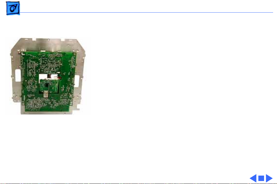
Troubleshooting Two Versions of the CRT/Video Board - 18
Two Versions of the CRT/Video Board
Important:
board was introduced. The second version is not backward
compatible with the previous version (the original board). You
must verify the version and replace boards like for like.
Check the serial number on the back of the display (rear
housing). A serial number of WR9451T8HOE or later means the
unit uses a version 2 board. To interpret the number, check the
date code embedded in the number.
WR945xxxxxx can be interpreted as aaywwxxxxxx, where
• y = last digit of year (1999)
• ww = week of year (45th week)
So any units produced after the 45th week of 1999 use the version
2 board (661-2231). And units produced before that week have a
version 1 board (661-2116) installed.
Visually identify the version of the board itself before performing
a board replacement. Check for a cylindrical standoff at the top of
the board, as shown. Version 1 has a standoff; version 2 does not.
In November 1999, a second version of the CRT/video
Note:
An alternate way of identifying the board version is to check
the 7-digit number (followed by a letter) on the solder side of the
board:
• 820-0997-A, B, C, or D = Version 1
• 820-1082-A, B, C, or D = Version 2
Page 49

K
Service Source
T ak e Apart
Studio Display (21" CRT, 19.8"
viewable image size)
Page 50

Take Apart Safety Guidelines - 1
Safety Guidelines
±
Warning:
vacuum picture tube. To prevent serious injury, review
CRT safety in Bulletins/Safety.
±
Warning:
discharging the CRT and setting up an ongoing ground
connection.
±
Warning:
sharp sheet-metal edges of the EMI shield, board chassis,
and other metal areas of the display assembly.
This product contains high voltage and a high-
Never use a grounding wriststrap until after
When the rear housing is removed, avoid the
Page 51

Take Apart New Tripod Stand Safety Tips - 2
New Tripod Stand Safety Tips
Important:
following:
• Lift the display by the hand grips under the left and right
sides of the display. Never lift the display by the tripod
stand.
• Likewise, do not adjust the position of the monitor by
pulling the stand legs. The tripod stand is subject to
cracking or breakage if mishandled.
• When placing the monitor on a table surface, ensure that
all three legs on the tripod stand contact the surface. If
one of the legs is too close to the table edge, the weight of
the monitor could cause the display to fall off the edge.
Because this is a new design, keep in mind the
Page 52

Take Apart Protecting the Translucent Housing - 3
Protecting the Translucent Housing
Important:
translucent plastic, surface scratches can be more visible
than on standard plastic housing. To avoid cosmetic damage
and protect the housing during service procedures, please
keep in mind the following precautions:
• Use a protective pad that is clean and free of debris
whenever you service the display.
• Use caution working with metal tools to avoid scratching
the housing.
• Before placing the display face on a book or ream of
paper, ensure the surface provides protection from
scratches.
Because the housing of this monitor is made of
Page 53

Take Apart Cable Reference - 4
Cable Reference
Important:
illustrations that show the detachable cables between the
boards.
You might find it helpful to print the cable illustrations and
refer to them when reassembling the display.
Refer to the Exploded View chapter for two
Page 54

Take Apart Service Tools - 5
Service Tools
Required Tools
The following tools are required to service the Studio
Display (21" CRT):
• Protective pad and a thick book or ream of paper on
which to place the display face down
• Magnetic Phillips screwdriver
• Magnetic, long T-15 torx driver
• Flat-blade screwdriver
• CRT discharge tool (Apple part number 076-0381)
• Thin metal flat-blade nail file (such as from a pocket
knife) or tweezers with a thin rounded end
• Popsicle sticks or orange stick (for wedging in-between
intermediate bezel and rear housing)
• Set of jeweler’s screwdrivers
Page 55

Take Apart Service Tools - 6
Suggested Tools
• Turntable (for easily repositioning the monitor)
• Needlenose pliers
Page 56

Take Apart USB Cover - 7
USB Cover
No preliminary steps are
required before you begin
this procedure.
Page 57

Take Apart USB Cover - 8
1 With the monitor
upright, use a flat-blade
screwdriver or
needlenose pliers to peel
off the USB label.
Replacement Note:
USB label should not be
re-used because the
adhesive may not hold
the label properly.
Therefore, replace the
USB label as described in
the next note.
The
Page 58

Take Apart USB Cover - 9
Replacement Note:
August 1999 a new color
version of the display
was introduced. The USB
label you use to replace
the old label must match
the housing color.
Replace the USB label
like for like (Apple part
number 922-3757 for
blue; Apple part number
922-4055 for gray).
In
Page 59

Take Apart USB Cover - 10
2 Use a Phillips
screwdriver to remove
the two screws.
Page 60

Take Apart USB Cover - 11
3 Lift away the plastic USB
cover from the housing.
Page 61

Take Apart Tripod Stand - 12
Tripod Stand
No preliminary steps are
required before you begin
this procedure.
Important: The tripod stand
should remain attached for
most of the Take Apart
procedures. The tripod stand
helps support the weight of
the display, and it enables
you to reposition the display
as needed during the
procedures.
Page 62

Take Apart Tripod Stand - 13
1 Place the display face
down on a raised padded
surface such as a thick
book or ream of paper.
2 Use a flat-blade
screwdriver to remove
the plastic insert on the
bottom of the tripod
stand.
Page 63

Take Apart Tripod Stand - 14
3 Looking through the
center opening, slide up
the tripod stand and
rotate the stand until the
inner tabs line up with
the slots in the bottom
housing.
4 When the inner tabs are
aligned, firmly grasp the
tripod stand and slide it
up as far as it will go.
Page 64

Take Apart Tripod Stand - 15
5 Pull the tripod stand
toward you to remove it
from the bottom housing.
(The two plastic rings
will drop as the tripod
stand is removed.)
Page 65

Take Apart Tripod Stand - 16
Replacement Note:
tripod stand (Apple part
number 922-3682)
includes the stand, the two
rings, and the plastic insert.
The
Page 66

Take Apart Rear Housing - 17
Rear Housing
Before you begin, remove
the USB cover.
Caution:
the rear housing, read all of
the steps in this procedure
before removing the rear
housing.
To avoid scratching
Page 67

Take Apart Rear Housing - 18
1
Caution:
display near a table
corner so you can rotate
the monitor and reach all
six rear housing screws
from below. Ensure all
three feet of the tripod
stand maintain contact
with the table.
With the screen facing
you, remove the two T15 torx screws at the
front underside of the
rear housing.
Position the
Page 68

Take Apart Rear Housing - 19
2 Rotate the display to
remove the remaining
four T-15 torx screws
that line the outer edge
at the underside of the
rear housing.
Page 69

Take Apart Rear Housing - 20
Important:
following non-marring
rounded tools to disengage
the rear housing tabs:
• Orange sticks and/or
popsicle sticks (up to
six)
• Ether a blunt nail file
from a pocket knife or
tweezers with a thin
rounded end
You need the
Page 70

Take Apart Rear Housing - 21
3 Check the seam where
the rear housing meets
the bezel. Notice the six
slots (two on top, two on
each side.
Page 71

Take Apart Rear Housing - 22
4 Starting at one side of
the rear housing, wedge
a rounded tool, such as
the nail file from a
pocket knife, into the
lower slot to disengage
the tab.
5 Flex the side of the rear
housing as you disengage
the first tab.
Page 72

Take Apart Rear Housing - 23
6 Wedge a popsicle stick or
orange stick into the
disengaged tab slot.
Continue around the side
and top of the rear
housing—using the nail
file or tweezers to
disengage each tab—then
place a popsicle stick or
orange stick in the slot
to keep the tab
disengaged. Continue
around the display until
all six tabs are
disengaged.
Page 73

Take Apart Rear Housing - 24
7 Pull the rear housing
back and off of the
display assembly.
8 Route the video cable and
USB cable through the
back panel opening.
Page 74

Take Apart Rear Housing - 25
Replacement Note:
position the rear housing
onto the display assembly,
• Check the back of the
display. Ensure the power
adapter and video/USB
cables are centered
correctly with the rear
housing openings.
• Then check each side of
the rear housing. Line up
the three integral pins on
the display assembly with
the holes in the rear
housing.
• Check the top of the
display. Line up the two
pins near the center.
As you
Page 75

Take Apart Rear Housing - 26
• When you are sure the
rear housing is lined up
correctly, face the
display screen and reach
around to the back of the
rear housing. With both
hands, press the rear
housing onto the display
assembly. You might need
to strike the top of the
rear housing, near the
intermediate bezel, to
snap it into place. Then
replace the screws.
Page 76

Take Apart Discharging the CRT and Removing the Anode Cap - 27
Discharging the CRT and Removing the Anode Cap
Before you begin, remove
• USB cover
• Rear housing
±
Warning:
contains high voltage and a
high-vacuum picture tube.
To prevent serious injury,
review CRT safety in
Bulletins/Safety and read
the safety guidelines at the
beginning of this chapter.
This product
Page 77

Take Apart Discharging the CRT and Removing the Anode Cap - 28
1 Use a flat-blade
screwdriver to press in
on one of the side tabs on
the anode cap cover. Lift
up that side. Repeat for
the other side.
Page 78

Take Apart Discharging the CRT and Removing the Anode Cap - 29
2 Tilt up the anode cap
cover and release it from
the two back slots on the
top EMI panel.
Page 79

Take Apart Discharging the CRT and Removing the Anode Cap - 30
3 Using the CRT discharge
tool (Apple part number
076-0381), connect
the clip to the metal CRT
frame and insert the
needle underneath the
anode cap to discharge
the CRT.
Page 80

Take Apart Discharging the CRT and Removing the Anode Cap - 31
4 Remove the anode cap
from the anode aperture.
Page 81

Take Apart Discharging the CRT and Removing the Anode Cap - 32
5 For working inside the monitor with the power off,
establish an ongoing ground by using a cable with
alligator clips at both ends. Connect one end to the anode
aperture, and connect the other end to the metal CRT
frame.
6 With the CRT discharged and the ongoing ground in place,
wear a grounding wriststrap to prevent equipment
damage from static electricity.
Page 82

Take Apart Back EMI Shield - 33
Back EMI Shield
Before you begin,
• Remove USB cover
• Remove rear housing
• Discharge CRT and
remove anode cap
Page 83

Take Apart Back EMI Shield - 34
1 Remove the eight
Phillips screws and star
washers that surround
the EMI shield.
Page 84

Take Apart Back EMI Shield - 35
2 Remove the two lower
Phillips screws that
secure the heatsink to
the back EMI shield and
the copper posts inside
the display assembly.
Replacement Note:
heatsink, included on earlier
versions of the display, is
not essential. So do not
replace the heatsink, but do
ensure the two screws still
secure the back EMI shield
to the copper posts.
3 Pull off the back EMI
shield from the rear of
the CRT/video board.
The
Page 85

Take Apart Back EMI Shield - 36
Caution:
removing the lower screws
on the heatsink can cause the
screws that secure the other
end of the copper posts to
become loose or fall inside
the unit. Therefore, after
the back EMI shield and top
EMI panel are removed,
check the screws at the
copper posts inside to
ensure no screws have
become lost inside the unit.
On some units,
Page 86

Take Apart Back EMI Shield - 37
Replacement Caution:
Secure the two inside screws
at the metal shield to the
copper posts first. Then
avoid overtightening the
outside screws at the back
EMI shield. Overtightening
the outside screws could
potentially loosen the inside
screws.
Page 87

Take Apart Top EMI Panel - 38
Top EMI Panel
Before you begin,
• Remove USB cover
• Remove rear housing
• Discharge CRT and
remove anode cap
• Remove back EMI shield
1 Remove the two Phillips
screws (with star
washers) from the top
EMI panel.
Page 88

Take Apart Top EMI Panel - 39
2 Lift up the back of the
top EMI panel until the
two back tabs clear the
slots.
3 Holding the back of the
EMI panel up, pull it
back to slide clear of the
side tabs.
Page 89

Take Apart Power Board - 40
Power Board
Before you begin,
• Remove USB cover
• Remove rear housing
• Discharge CRT and
remove anode cap
• Remove back EMI shield
• Remove top EMI panel
Page 90

Take Apart Power Board - 41
1 Remove the three
Phillips screws and star
washers that secure the
power board’s shield to
the display assembly.
Page 91

Take Apart Power Board - 42
2 Swing out the power
board on its hinges. Then
lift it up and move it off
the hinge hooks.
Page 92

Take Apart Power Board - 43
3 Open the cable clamp,
and disconnect the
following cables:
• 2-pin locking
connector from BP6
• 9-pin connector from
BP4
• 12-pin connector
from BP5
• 10-pin locking
connector from BP3
Replacement Note:
Depending on when the
unit was made, the
power board can have up
to three cable clamps.
Page 93

Take Apart Power Board - 44
4 Disconnect 2-pin
locking connector BP2,
located at the bottom of
the power board by the
fuse.
5 Remove the power board
from the display
assembly.
Page 94

Take Apart Power Board - 45
Replacement Note:
power board part includes
no detachable cables.
Replacement Note:
the illustration “Detachable
Cables: Power Board and
CRT/Video Board” in the
Exploded View chapter.
The
Refer to
Page 95

Take Apart Main Deflection Board - 46
Main Deflection Board
Before you begin,
• Remove USB cover
• Remove rear housing
• Discharge CRT and
remove anode cap
• Remove back EMI shield
• Remove top EMI panel
Page 96

Take Apart Main Deflection Board - 47
1 Open the cable clamp
that secures the anode
cable to the plastic yoke
on the CRT.
2 Refer to “CRT/Video
Board” in this chapter to
remove the red and white
focus wires from the
CRT socket.
Page 97

Take Apart Main Deflection Board - 48
3 Remove the three
Phillips screws and star
washers that secure the
main deflection board
shield to the display
assembly.
Page 98

Take Apart Main Deflection Board - 49
4 Gently swing out the
board on its hinges.
Page 99

Take Apart Main Deflection Board - 50
5 Swing out the main
deflection board far
enough until you can see
that the bottom bracket
at the inside corner
clears the video cable at
its strain relief.
Page 100

Take Apart Main Deflection Board - 51
6 Lift up the main
deflection board and
move it off the three
hinge hooks.
7 While supporting the
board, disconnect
• 10-pin locking
connector from BA9
(to power board)
• 3-pin locking
connector BF1 (to
yoke)
• 9-pin connector BA8
(to power board)
• 2-pin locking
connector BL1 (to
yoke)
 Loading...