

Page 1
Shake 4
Tutorials
Page 2

Apple Computer, Inc.
© 2005 Apple Computer, Inc. All rights reserved.
Under the copyright laws, this manual may not be
copied, in whole or in part, without the written consent
of Apple. Your rights to the software are governed by
the accompanying software license agreement.
The Apple logo is a trademark of Apple Computer, Inc.,
registered in the U.S. and other countries. Use of the
keyboard Apple logo (Option-Shift-K) for commercial
purposes without the prior written consent of Apple
may constitute trademark infringement and unfair
competition in violation of federal and state laws.
Every effort has been made to ensure that the
information in this manual is accurate. Apple Computer,
Inc. is not responsible for printing or clerical errors.
Apple Computer, Inc.
1 Infinite Loop
Cupertino, CA 95014-2084
408-996-1010
www.apple.com
Apple, the Apple logo, Final Cut, Final Cut Pro, FireWire,
Mac, Macintosh, Mac OS, Nothing Real, QuickTime,
Shake, and TrueType are trademarks of Apple Computer,
Inc., registered in the U.S. and other countries.
Adobe and Photoshop are trademarks or registered
trademarks of Adobe Systems Incorporated in the U.S.
and/or other countries.
Cineon is a registered trademark of Eastman Kodak
Company.
Maya, Alias, and Alias|Wavefront are trademarks or
registered trademarks of Alias Systems Corp. in the U.S.
and/or other countries.
IRIX is a registered trademark of Silicon Graphics, Inc.
3ds Max is a registered trademark of Autodesk Inc.
Other company and product names mentioned herein
are trademarks of their respective companies. Mention
of third-party products is for informational purposes
only and constitutes neither an endorsement nor a
recommendation. Apple assumes no responsibility with
regard to the performance or use of these products.
Page 3

Contents
1
Preface 7Welcome to Shake 4
7
The Tutorial Lessons
8
Installing the Tutorial Media
8
Mac OS X Notes
Chapter 1 11 Shake Basics
11
Tutorial Summary
12
A Tour of the Basics
16
Loading Images
19
Viewing Images, Parameters, and Channels
24
Working With Windows
24
Launching a Flipbook
26
Compositing Elements
31
Setting Resolution
33
Filtering and Masking
34
Tuning Parameters
37
Working With Layer Nodes
40
Transforming an Image
41
Fading an Element
43
Rendering a Sequence
Chapter 2 47 Intermediate Skills
47
Tutorial Summary
48
Inserting Nodes Into a Tree
50
Grouping Nodes and Using SetDOD
55
Using the Time View
66
Creating Motion Blur
71
Importing Photoshop Files
75
Keyframe Animation and the Curve Editor
80
Color Correction
Chapter 3 91 Depth Compositing
91
Tutorial Summary
92
Simulated Depth and 3D Compositing
3
Page 4

4
93
98
Working With Z Channels
Creating Composites With ZCompose
10 2 Color Correcting Premultiplied Images
10 7 Fading With Distance
111 3D Compositing With the MultiPlane Node
121 Animating a MultiPlane Camera
12 5 Importing Camera and Animation Data
Chapter 4 13 3Working With Expressions
13 3 Tutorial Summary
13 3 Creating the Fan Composite
13 6 Creating a Light Source With RGrad
13 8 Looping Frames in the Time View
13 9 Using Local Variables and Expressions
14 4 Simulating Volumetrics With RBlur
15 3 Concatenating Color Adjustments
15 6 Adding Motion Blur to Pre-Animated Elements
Chapter 5 163Using Keylight
163
Tutorial Summary
164
Using Keylight to Pull a Key
165
Testing the Mask With a Viewer Script
167
Adjusting the Mask With Parameters
169
Masking
17 2
Color Correcting the Foreground Image
17 5
Advanced Keylight Techniques
17 8
Using fgBias to Remove Blue Spill
17 9
Using a Holdout Matte
Chapter 6 183Using Primatte
183
Tutorial Summary
183
The Basics of Pulling a Key in Primatte
18 6
Inner Mechanics of Primatte
191
Masking Primatte
19 4
Spill Suppression in Primatte
200
Compositing Outside of Primatte
Chapter 7 201 Tracking and Stabilization
201
Tutorial Summary
201
Tracking and Stabilizing Nodes
202
Stabilizing an Image Sequence
206
Converting Stabilization Data to MatchMove Data
208
Using the MatchMove Node
Contents
Page 5

215 Position the Foreground Element
218 Color Correct the Foreground Element
Chapter 8 225Working With Macros
225 Tutorial Summary
225 What Is a Macro?
226 Creating a Handmade Macro
232 Saving and Testing the Macro
234 Adding a Button to the Interface
237 How to Set Slider Ranges
238 Creating Macros With MacroMaker
241 Creating Sliders in MacroMaker
Chapter 9 243 Creating Clean Plates
243
Tutorial Summary
243
Stitching Images
247
Stabilizing and Stitching Background Plates
252
Creating a Clean Plate With QuickPaint
Contents
5
Page 6

6
Contents
Page 7

Welcome to Shake 4
This guide includes hands-on tutorials, demonstrations,
and explanations of Shake features and workflow.
In addition to the fundamental topics, this guide also explains specialized topics, such
as 3D compositing, expressions, keying, and tracking. Check the lesson summaries
below for a quick overview of each tutorial.
Preface
For further study, you’ll want to explore the
book (also available in PDF format from the onscreen Help menu and in the
directory) that contains detailed information about color correction, keying and spill
suppression, masking, transforms, premultiplication, bit depth, logarithmic color space,
caching and optimization, and other Shake features. The
includes a helpful “Cookbook” chapter with additional tips and macros to improve your
workflow and productivity.
Shake 4 User Manual
Shake 4 User Manual
. This is a two-volume
Shake/doc
also
The Tutorial Lessons
•
Tutorial 1: “Shake Basics”
tasks, including loading and compositing images, tuning parameters, transforming
images, adding masks, and rendering.
•
Tutorial 2: “Intermediate Skills”
with the
You will also learn how to add motion blur, how to color-match the elements in a
composite, and how to import Photoshop files as layers in a composite.
•
Tutorial 3: “Depth Compositing”
creating “real” and simulated depth in your composites. You’ll start with Z channels
and filtering options. Then you’ll work with Shake’s
Tutorial 4: “Working With Expressions”
•
animation with expressions, rather than keyframes.
Tutorial 5: “Using Keylight”
•
Keylight
performing spill suppression.
SetDOD
node: pulling keys, applying masking, creating holdout mattes, and
—This tutorial introduces Shake through a series of common
—This tutorial shows how to optimize your workflow
node, and how to use the Shake Time View, and the Curve Editor.
—This tutorial demonstrates different methods for
MultiPlane
—This tutorial shows how to generate
—This two-part lesson covers the basics of using the
node.
7
Page 8

•
Tutorial 6: “Using Primatte”
Photron Primatte keying plug-in, as well as masking and spill suppression.
•
Tutorial 7: “Tracking and Stabilization”
for Shake’s tracking technology, including removing unwanted motion from an
image sequence and “matchmoving” an element to the motion of another element
in the composite.
Tutorial 8: “Working With Macros”
•
groups of commands, called macros. In this example, you’ll set up a basic macro for a
motion blur effect that is adjustable to any angle.
•
Tutorial 9: “Creating Clean Plates”
with the
You will also use the
AutoAlign
node, and how to use the
—This lesson describes the basic use and mechanics of the
—This tutorial demonstrates the primary uses
—This tutorial demonstrates how to create reusable
—This tutorial demonstrates how to stitch images
QuickPaint
SmoothCam
node to create a clean background plate.
node to stabilize footage.
Installing the Tutorial Media
Before you continue with the tutorials, you need to install the tutorial media. The
sample files for the lessons are located on the Shake Installation disk, in the
Documentation/Tutorial_Media
from the Shake Installation website.
•
Installation CD:
your
$HOME/nreal
•
Online (Linux/IRIX Users):
password to access the download site for the Shake tutorial media.
Copy the
directory.
directory. Licensed users can also download these files
Tutorial_Media
Contact your system administrator for the URL and
folder from the
Documentation
directory to
Note:
Tutorial_Media
Mac OS X Notes
The following information applies to Shake on the Mac OS X platform:
Using the Three-Button Mouse
You must use a three-button mouse with Shake as many functions are not possible
with a single- or two-button mouse. The middle scroll wheel commonly serves as the
middle mouse button. Many commands in Shake require you to “middle-click.”
The Delete Key
The Macintosh Delete key located below the F12 key is the equivalent of the Linux
Backspace key; the Macintosh Delete key grouped with the Help, Home, and End keys
is the equivalent of the Linux Delete key.
8 Preface
You can install the tutorial media files anywhere you like, but the
directory is used in this guide to simplify the process of instruction.
Welcome to Shake 4
$HOME/nreal/
Page 9

Important: Macintosh users should bear in mind that the Delete key used in Shake is
not the key located below the F12 key but, rather, the one grouped with the Help,
Home, and End keys. If you are using a smaller Macintosh keyboard without the second
Delete, use Option-Delete (again, the key below F12).
Keyboard Command Differences Between Platforms
Some keyboard commands are different between the Mac OS X platform and the Linux
or IRIX platform. In most cases in this documentation, the Macintosh keyboard
command is cited first, followed by the Linux/IRIX command.
Control vs. Command
On the Mac OS X platform, you can use the Control or Command key interchangeably.
For example, use Control-C or Command-C to copy an object.
Launching Shake in the Terminal
Mac OS X wraps up binaries and their contents into one icon in the Finder. Click the
Shake icon in Mac OS X to launch Shake, or right-click the Shake icon to obtain menu
options. For example, right-click the Shake icon and choose Show Package Contents
from the shortcut menu to open the subdirectories. Alternatively, you can use the
Terminal to navigate to shake.app/Contents/MacOS/ to find the actual binary files.
Preface Welcome to Shake 4 9
Page 10

10 Preface Welcome to Shake 4
Page 11
1 Shake Basics
This tutorial introduces Shake through a series of
common tasks, including loading and compositing
images, tuning parameters, transforming images, adding
masks, and rendering.
1
Tutorial Summary
• A tour of the basics
• Loading images
• Viewing images, parameters, and channels
• Working with windows
• Launching a Flipbook
• Compositing elements
11
Page 12

• Setting resolution
• Creating a new element
• Tuning parameters
• Working with layer nodes
• Transforming an image
• Applying a mask
• Rendering a sequence
A Tour of the Basics
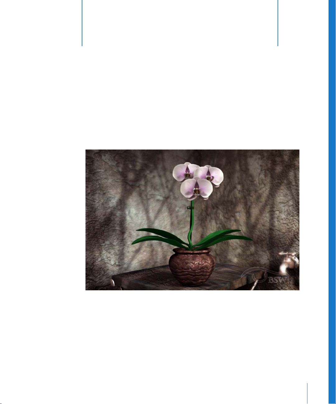
In this tutorial you’ll create a composite with images created at Big Sister's Watching,
NY by Brandon Robinson and Melissa Graff.
You’ll start by layering the images for the composite. Then you’ll incorporate additional
elements for soft shadows and lighting. Before you begin, let’s review some basic
Shake operations.
Launching Shake
You can launch the Shake application from your desktop or from the command line,
assuming the Shake binary files are located in the directory created for Shake during
installation.
To launch Shake:
m
On the Mac OS X platform, browse to the application directory and double-click the
Shake icon, or simply click the Shake icon in the Dock.
m
On the Linux or IRIX platform, enter the following in any shell:
shake
For you Mac users, the Shake icon may appear on the Dock. If it’s not there, then you
can drag it to the dock from the application directory. You can also launch from the
Mac OS X Terminal, but you must type the complete path to Shake (that is,
Applications/Shake/shake.app/Contents/MacOS/shake), or set the appropriate
environment variables.
Note: For more information, see “Environment Variables for Shake” in Chapter 14 of the
Shake 4 User Manual.
12 Chapter 1 Shake Basics
Page 13
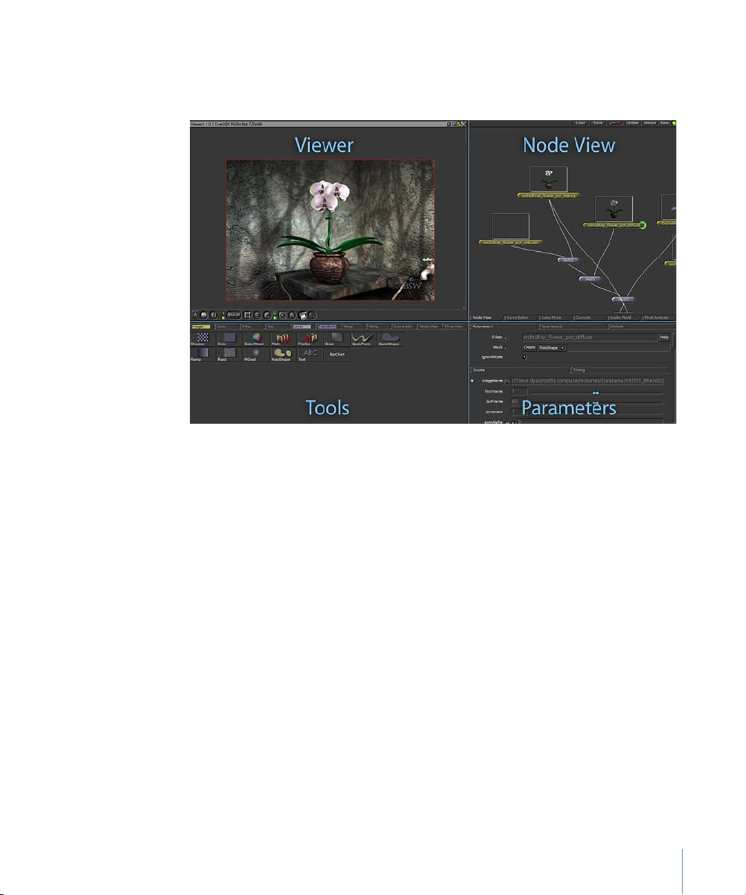
Using the Shake Panels
When you start Shake, you’ll notice that the interface is divided into four panels: Viewer,
Node View, Tools, and Parameters.
Each image process in Shake is accomplished by connecting items, called nodes, as a
tree structure in the Node View. The result is an overview of the images, layers, and
processes in your project. Shake projects are called scripts because the results are
stored as a list of sequential commands in a script file.
So, where do the nodes come from? The Tools panel lists the objects and functions—
the nodes—that you can add to your script. The Viewer shows the output of a selected
node in the script. The Viewer is also the place where you use interactive controls to
transform images and create shapes.
In the Parameters panel, you edit a selected node or change project settings on the
Globals tab. And, speaking of tabs, three of the four panels are divided into a number
of tabs that allow access to commands, additional parameters, and other functional
windows, like the Curve Editor and Audio Panel.
You don’t need to know all the screen controls at this point, but you’ll probably have
some questions while you’re working through this tutorial. Being the advanced
compositing artist that you are, you never crack open the user documentation—except
for this tutorial guide, of course—so how can you figure out what all the screen items
do? Contextual help, that’s how!
Chapter 1 Shake Basics 13
Page 14
Contextual Help
Move the mouse pointer over a control or parameter to display brief help messages in
the Info field at the bottom of the screen. These messages explain what each item does
and also show any relevant hot keys.
The Info field displays
context-sensitive help.
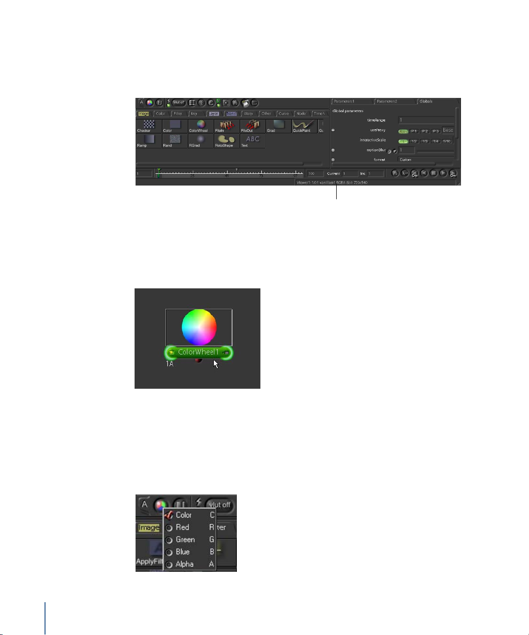
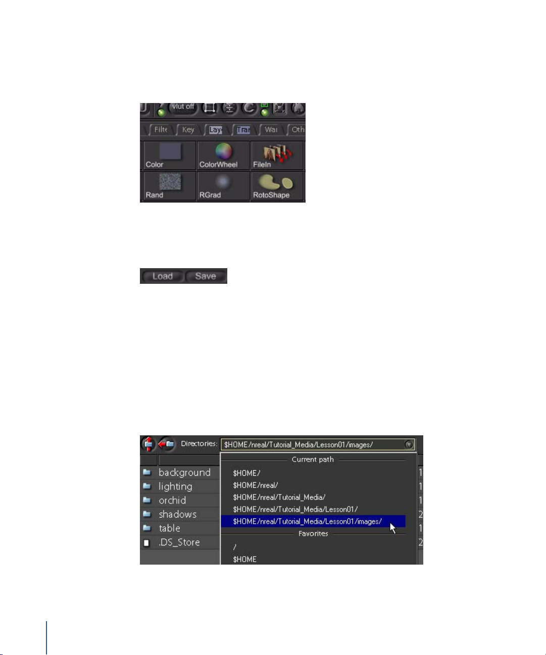
For example, suppose you want to know what would happen if you clicked on the
ColorWheel command on the Image tab. Move your pointer over the command and
the message Create node: “ColorWheel()” appears in the Info field. Go ahead, click it if
you want. You’ll add a ColorWheel node to the Node View.
Your first color wheel!
Shortcut Menus and Lists
In addition to the contextual help, you can right-click many controls to display shortcut
menus with additional commands and functions. Try this: Right-click the View Channel
button. A shortcut menu appears with the hot keys for each channel display option.
14 Chapter 1 Shake Basics
Page 15
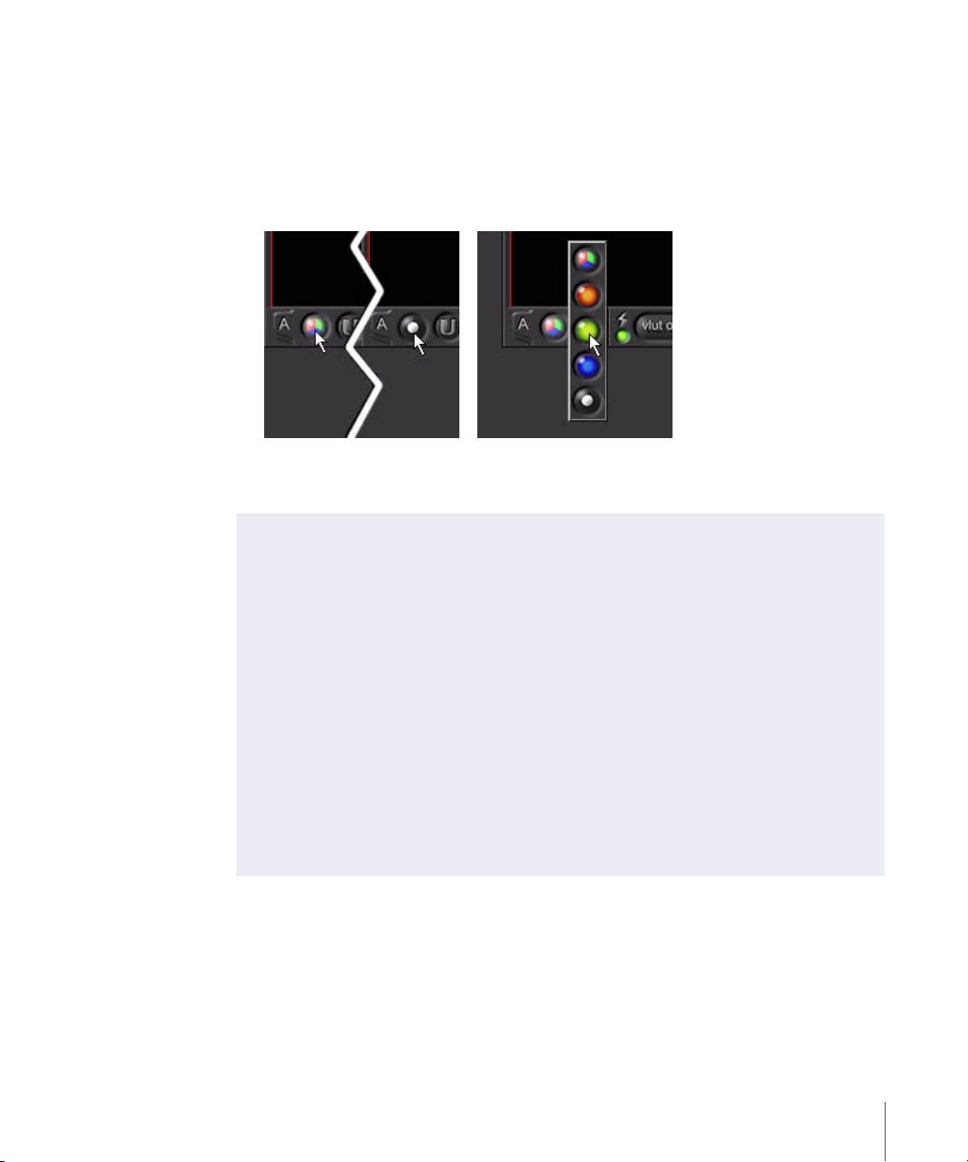
For many onscreen controls, there are also click-and-hold behaviors:
• Click a button to toggle between its two default states. For example, click the View
Channel button to toggle between RGB and alpha channel views.
• Press and hold a button to select an option from a pop-up list. When you press and
hold the View Channel button, for example, you can select from a list of available
channel options.
Click to toggle between RGB and
alpha views.
Press and hold to choose from a pop-up menu.
Overriding the Default Button Choices
To override the default choices, Control-click and hold to choose your next option.
For example, the default button behavior for the View Channel button is to toggle
between RGB view and alpha view. To modify the behavior to toggle from RGB view
to red channel view to alpha channel view and then back to RGB view, perform the
following steps:
1 Make sure the View Channel button is set to RGB (Color) View.
2 Control-click and hold the button, then choose the Red Channel button from
the pop-up menu.
3 Control-click and hold the button, then choose the Alpha Channel button.
Because the alpha view already toggles to RGB view, you do not have to Control-click
and hold again to toggle back to RGB view.
To save this behavior, choose File > Save Interface Settings.
Chapter 1 Shake Basics 15
Page 16
Loading Images
To load images into your project, you use the FileIn node from the Image Tool tab. In
these tutorials, the notation for creating nodes is identified with this format: Tab NameNode Name, as in “insert an Image-FileIn node”.
Note: Do not confuse the FileIn node with the Load and Save buttons at the upper-
right corner of the screen. The Load and Save buttons are for retrieving and saving
Shake scripts.
If you still have that ColorWheel node in the Node View, you need to remove it. Click
once on the node to select it, then press the Delete (Mac OS X) or Backspace (IRIX/
Linux) key.
To load the images:
1 In the Image tab, click FileIn to launch the File Browser.
2 Browse to the $HOME/nreal/Tutorial_Media/Tutorial_01/images directory.
Note: See “Browsing Tips” below for information on saving this directory to a list of
favorites.
16 Chapter 1 Shake Basics
Page 17
3 Double-click the background directory to open it, select the background.30-59@.jpg
image sequence, then click Next at the bottom of the browser (or press the Space bar).
You click Next instead of OK to select additional files. When you’re done, you’ll load all
the images at once.
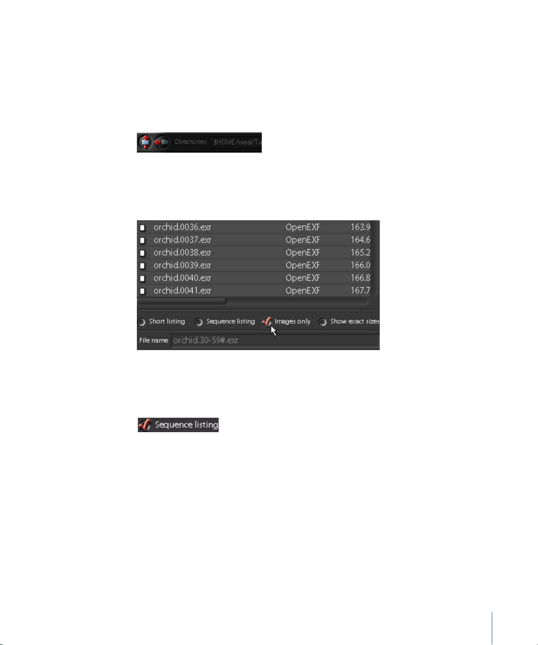
4 Click the Up Directory button, and browse to the orchid directory where you’ll find the
orchid.30-59#.exr image sequence.
The “30-59” tells you this is a sequence of 30 frames. The # symbol indicates frame
numbers padded with zeros, so that all frames have four-digit numbers. Don’t believe it?
5 Just for fun, click to deselect the “Sequence listing” checkbox.
You’ll see the individual files in the image sequence. This is a good thing to know if you
ever need to load just one frame from a sequence.
6 Click to select the Sequence listing box again to switch back to the original view.
7 Select the orchid.30-59#.sgi image sequence, then click Next.
8 Click the Up Directory button and navigate to the table directory, where you’ll find the
table.30-59@.exr image sequence.
This sequence name includes the @ symbol instead of the # symbol. The @ symbol
indicates these frame numbers are not padded with leading zeros. Toggle the
“Sequence listing” option and you’ll see.
9 To load the sequence, activate “Sequence listing,” then select table.30-59@.exr. This time,
do not click Next!
10 Click OK to include the last file and close the browser.
Chapter 1 Shake Basics 17
Page 18
.
Browsing Tips
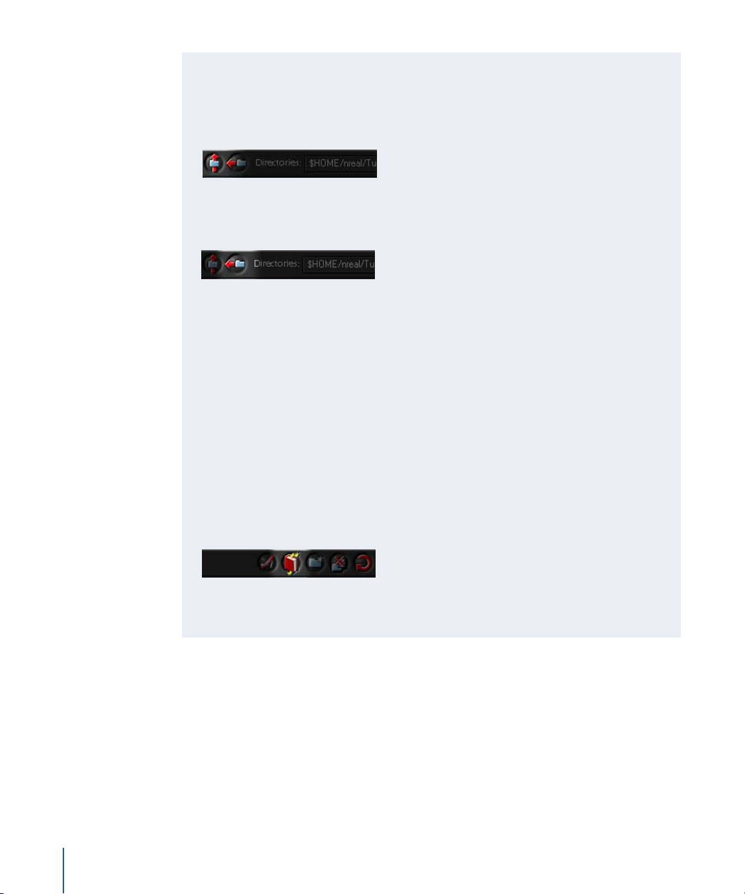
There are several ways to navigate within the File Browser:
• To move up one level, click the Up Directory button or press Delete (Mac OS X), or
press Backspace (IRIX or Linux).
• To move back to the previously viewed directory, click the Previous Directory
button.
• To move down one level, double-click a directory.
• To scroll by file, click in the file list, then press the Up Arrow or Down Arrow key to
scroll up or down.
• To scroll using the mouse, middle-click and drag or Option-click and drag (Mac OS
X), or Alt-click and drag (you do not have to use the scroll bar on the right). You can
also use the mouse scroll wheel.
• To jump to a file name, type a letter to move to the first file that starts with that
letter.
• To review browsing history, use the Directories pop-up menu, which lists the files in
your $HOME directory, as well as recently visited directories and favorite project
directories.
• To save a favorite location, click the Bookmark button near the top of the File
Browser. The current location is saved to a list of favorites.
• To import multiple files, click Next, or press the Space bar. On the last file, click OK
to import all selected files and close the File Browser.
After you click OK, the selected images appear as FileIn nodes in the Node View. They
might overlap each other, but this is easy to fix.
18 Chapter 1 Shake Basics
Page 19
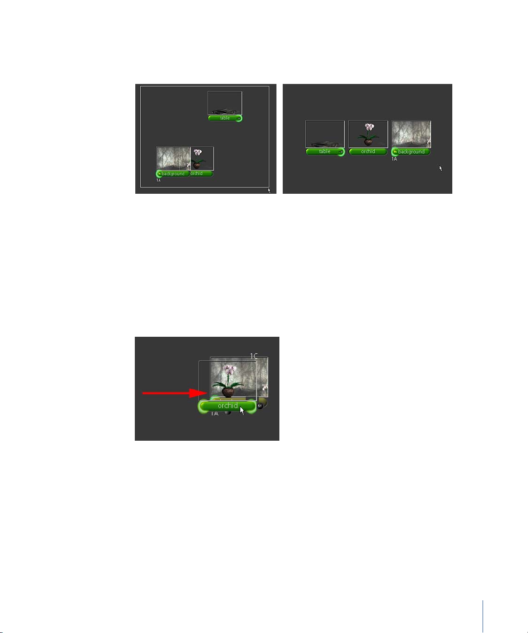
11 Drag a selection box around all the nodes, then press L on your keyboard to line them
up. You can also right-click in the Node View and choose Node Layout > Layout
Selected from the shortcut menu.
Viewing Images, Parameters, and Channels
Each node represents a function or operation that can be viewed or modified. In this
case, these are FileIn nodes that reference images from your disk directories. As shown
in the previous illustration, image thumbnails appear above the nodes. If there is an
accompanying alpha channel, a thumbnail includes transparency, as well. To test this,
drag the mid node over the background node in the node tree and you’ll create a mini-
composite. Does this help you composite at all? No, but it gives you a quick preview of
what the composite might look like.
To create an actual composite, you must connect the nodes. This happens in a
moment, so stop fidgeting.
Working With Thumbnails
When working with thumbnails, bear in mind the following:
• The thumbnails represent the frame at the time of file loading.
• To refresh for the current frame, select the node and press R with the pointer in the
Node View.
Chapter 1 Shake Basics 19
Page 20
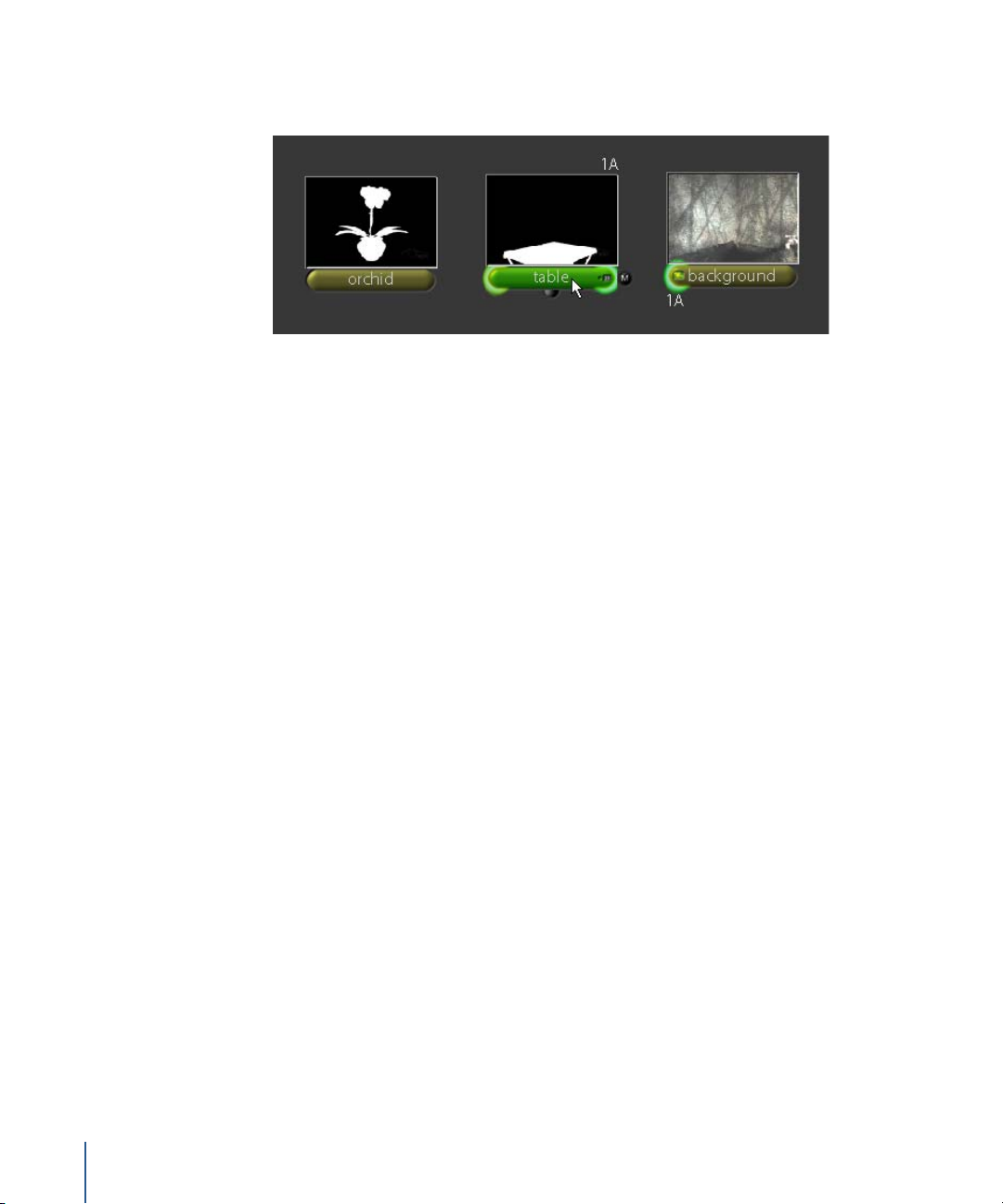
• To view the alpha channel, place the pointer over the thumbnail and press A. To
return to the RGB view, place the pointer over the thumbnail and press C for “color.”
• Any node can have a thumbnail—select the node and press T.
Note: The thumbnails do not dynamically update (see below).
• To hide thumbnails, select the nodes and press T. Press T again to show the
thumbnails.
• Additional controls for the thumbnails are located in the Globals tab.
Shake does not dynamically update thumbnails because it can be inefficient and
inaccurate. For example, if you’re working on 6K plates, do you really want to spend all
of your time resizing 6K plates down to tiny icons? (Please say “no.”)
Suppose your script has 900 nodes, which I think we can all agree is not unlikely.
Continually updating all thumbnails would require... well, that’s a lot of coffee breaks.
The most efficient and accurate way to check a node is to load it into the Viewer.
This leads us to the next topic, loading and viewing nodes.
Viewing a Node or Loading Its Parameters
There are several ways to activate the controls on a node:
• To load a node into the Viewer, click the left side of the node.
20 Chapter 1 Shake Basics
Page 21
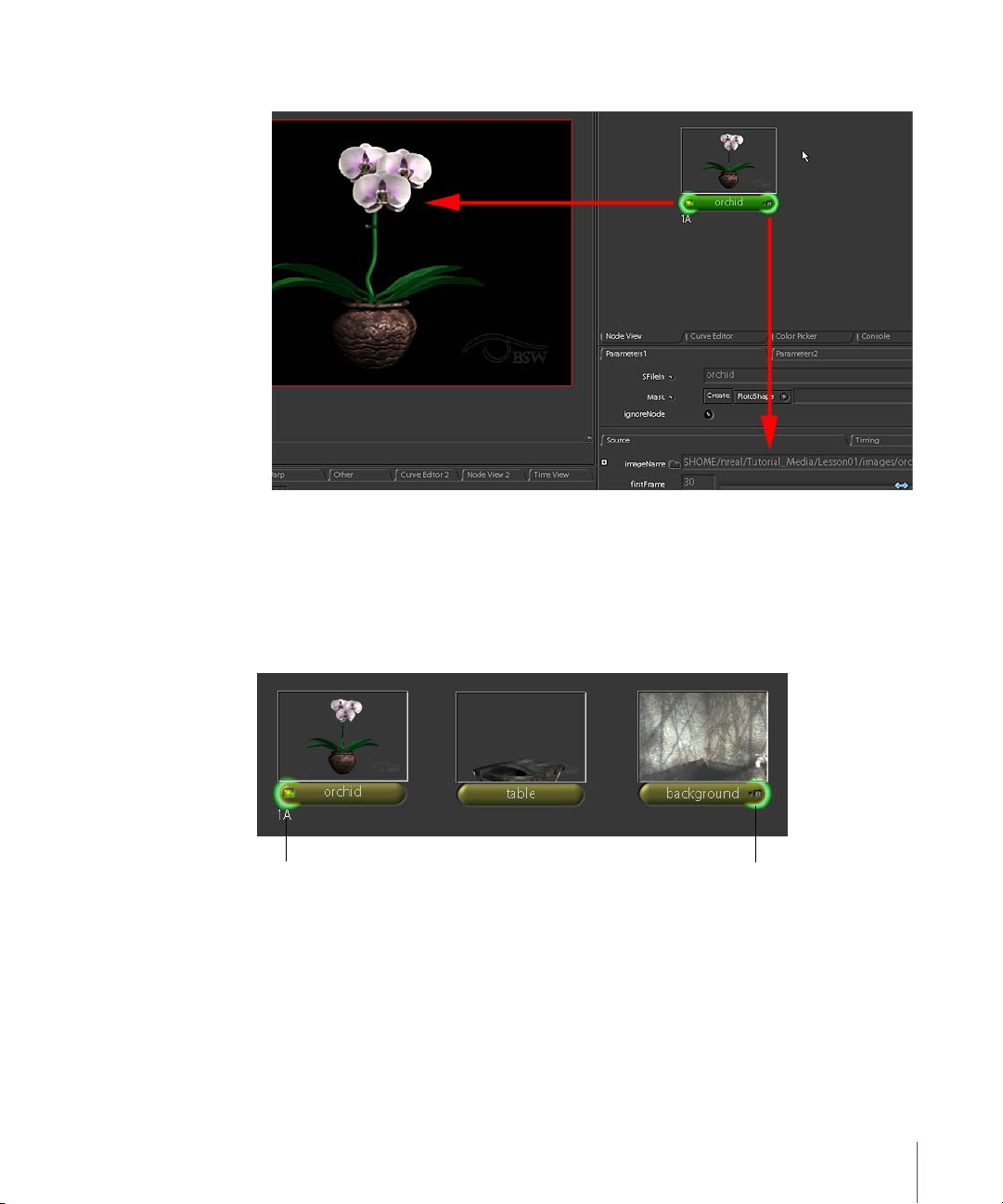
• To load the parameters into the Parameters tab, click the right side of the node.
• To load a node into the Viewer and the Parameters tab simultaneously, double-click
the node.
Sometimes, you need to edit the parameters of one node while viewing the output
from another. For example, you’ll often want to adjust a color correction while looking
at the result in the final composite.
Loaded into Viewer 1,
buffer A.
Loaded into the
Parameters tab.
In the illustration above, the orchid node is loaded into the Viewer—the highlight on
the left side of the node is the Viewer indicator. The 1A label also appears below the
node to indicate it is loaded into Viewer 1, buffer A (stay tuned for information on
Viewer buffers).
Chapter 1 Shake Basics 21
Page 22
The gray square on the right side of the background node—it’s supposed to be a tiny
text field—indicates that this node is selected for editing in the Parameters tab. So why
is this useful? In a real composite—you’ll have one soon—you’ll often want to adjust a
node while viewing the end result at the final output node in your script.
We mentioned contextual help for screen controls, and this also works to get
information about nodes. As you pass the pointer over a node (no need to click), the
resolution, bit depth, node name and type, and channels are displayed in the Info field
of the Shake window. For example, move the pointer over the FileIn node named
background, and you’ll see that it stores an 8-bit image, with RGB channels, and a
resolution of 720 x 486 pixels.
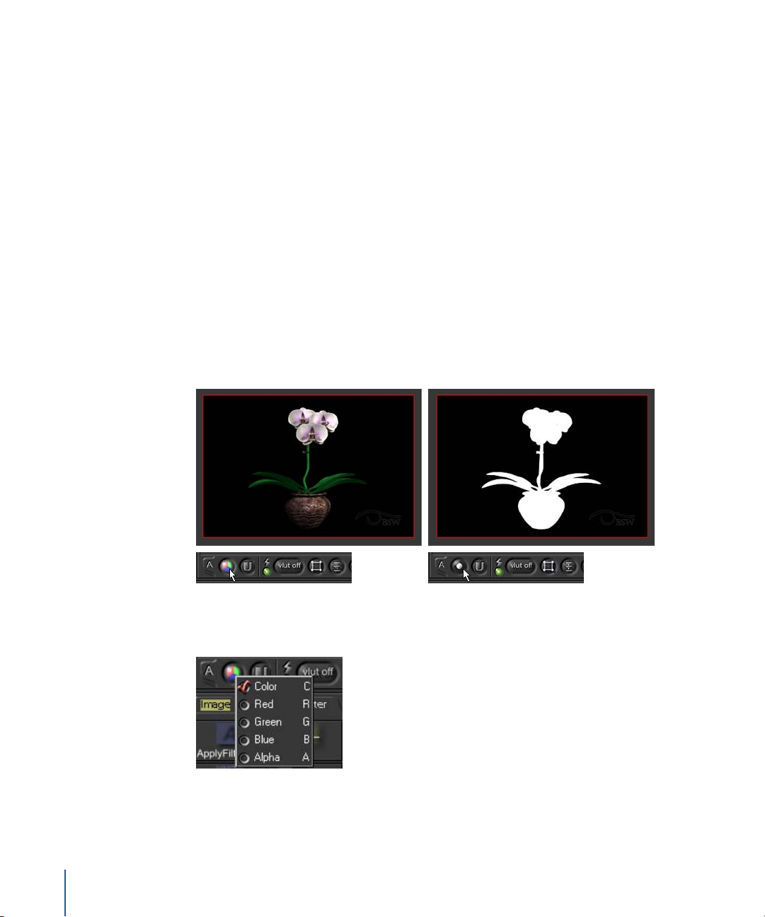
Displaying Different Channels in the Viewer
Use the View Channel button to toggle the display of different channels in the Viewer.
This is important when you want to check the quality of matte edges or transparencies
in the alpha channel. You’ll also need to view independent R, G, or B channels for many
color-correction operations. For example, click the View Channel button to toggle to
the alpha channel view.
There you see the alpha channel. However, nobody actually uses the View Channel
button. Remember when you right-clicked this button to see the hot keys?
Use the hot keys when the pointer is in the Viewer to quickly view a channel (C, R, G,
B, or A).
22 Chapter 1 Shake Basics
Page 23
Panning, Zooming, and Framing
While working in Shake, you’ll need to pan, zoom, and frame the contents of the Node
View, the Viewer, and other windows in Shake.
• To pan: Drag the pointer over a window while pressing the middle mouse button. Or,
drag the pointer while pressing Option (Mac OS X) or Alt (Linux/IRIX)
• To zoom: Drag the pointer over the window while pressing Control-Option (Mac OS X)
or Control-Alt (Linux/IRIX). You can also press plus (+) or minus (–) to zoom in or out.
• To frame: Move the mouse pointer over the window and press F.
• To expand or shrink the window: Move the pointer over a panel and press the Space
bar This toggles the window between full-screen and standard view.
Setting the Frame Range
There are two places to set the frame range in Shake. The first and most important is in
the Globals tab. The Globals tab lists all script settings—the frame range, proxy
settings, default resolutions, GUI settings, and quality settings. The first Parameters tab
contains a listing of parameters for a selected node.
There are two ways to show the Globals tab:
m
Click the Globals tab.
m
Double-click an empty area in the Node View.
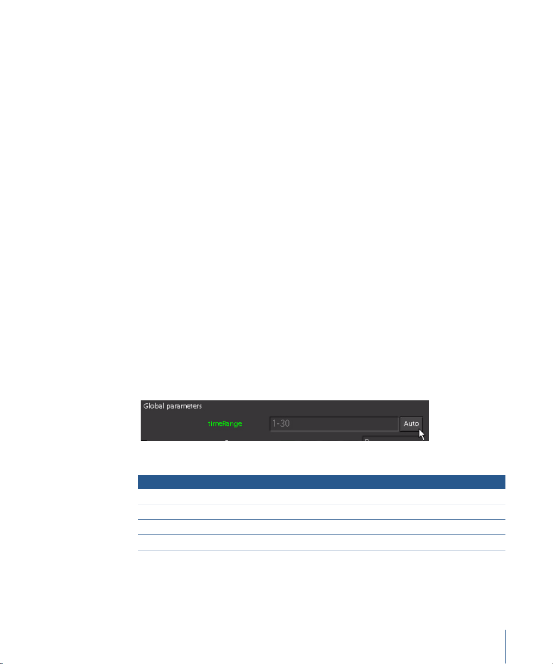
The first parameter in the Globals tab is the timeRange parameter. This frame range
determines which frames are rendered. Although it is saved in the script, you can
override it in the command line. Click the Auto button to examine the FileIn nodes and
determine the frame range automatically.
To enter the time range:
m
Click Auto in the timeRange parameter.
The timeRange parameter is extremely flexible because you can customize the range:
Entry Calculates
1-56 Frames 1 to 56
20-30 11 images from frames 20 to 30
1-56x3 Frames 1, 4, 7, and so on
1,10,20-30x2 Frames 1, 10, 20, 22, 24, 26, 28, and 30
Chapter 1 Shake Basics 23
Page 24
Working With Windows
Now that you have a few images loaded, this is a good time to practice methods of
working with the Shake windows.
Function Keyboard Notes
Expand a window full screen Space bar Press the Space bar again to
zoom back to normal view.
Pan a window Middle-click and drag, or Option-
click and drag (Mac OS X); Alt-click
and drag (Linux/IRIX)
Zoom a window Command–middle-click and drag,
Control–middle-click and drag, or
Control–Option-click and drag
(Mac OS X); Control–Alt-click and
drag (Linux/IRIX)
Zoom in on a Viewer + / – (under the Mac OS X function
keys); Backspace key (Linux/IRIX)
Reset a View Home Works in the Node View, the
Resize a pane Grab the border between two
Works in all windows, including
the File Browser.
Works in the Node View, the
Viewer, the Time Bar, and the
Curve Editor.
Gives you an integer-based
zoom so you have fewer roundoff artifacts on your display. The
zoom follows the pointer.
Viewer, the Time Bar, and the
Time View.
panes and drag to resize the
window.
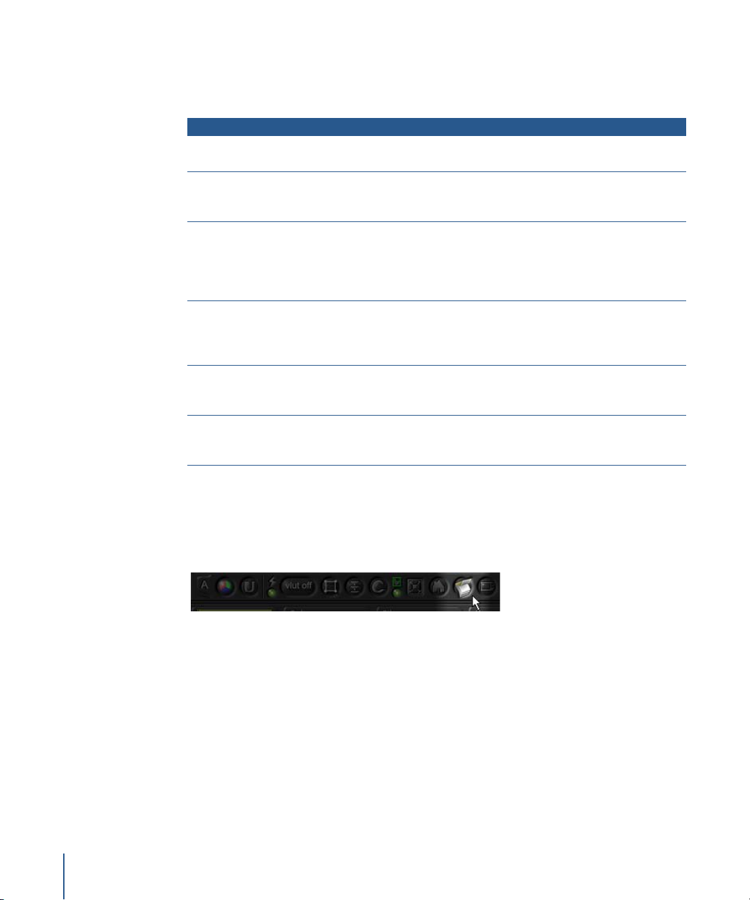
Launching a Flipbook
In the Viewer shelf, click the Flipbook button to render a Flipbook for the node
displayed in the current Viewer.
If a FileOut node is selected, the actual FileOut is not executed. To render to disk, use the
Render command (right-click in the Node View, or use the Render menu). Otherwise,
the sequence is rendered into memory and you can play it back.
24 Chapter 1 Shake Basics
Page 25
Flipbook Controls
The following table contains several Flipbook controls.
Control Action
. (Period; think of it as the > key.) Play forward.
, (Comma; think of it as the < key.) Play backward.
R, G, B, A, C Show the red, green, blue, alpha, and color channels.
Shift-drag Scrub through the animation.
Escape (Esc) Close the window.
You can have as many Flipbooks as memory allows, but once closed, all links to the
Flipbook are lost—you cannot save or use the images again. You can stow the
Flipbooks and retrieve them later, but they take up memory.
You can also use the Time Bar to indicate a frame range and obtain playback. The Time
Bar displays the range that you want to concentrate on, and does not get saved into
the script.
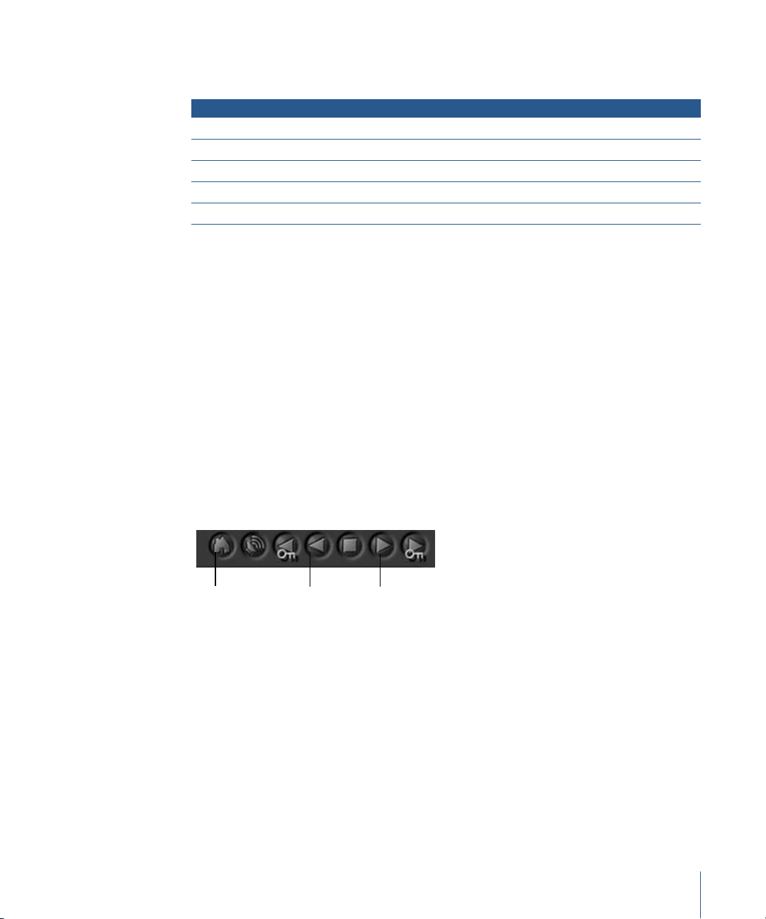
To set the playback range for the Time Bar:
m
Place the pointer over the Time Bar and press Home on the keyboard (or click the
Home button in the Time Bar) to load the script’s timeRange into the Time Bar.
To play the sequence in the Viewer:
m
Click the Play forward button in the Time Bar to play through the sequence. Playback
does not occur in not real time, but does place the images into the memory cache,
optimizing future calculations in the interface.
Home
m
Shift-click the Play Forward button to playback from the images cached to disk from
Play
backward
Play
forward
the Time Bar.
For more information on the Flipbook, see “The Flipbook, Monitor Previews, and Color
Calibration” in Chapter 11 of the Shake 4 User Manual.
Chapter 1 Shake Basics 25
Page 26
Compositing Elements
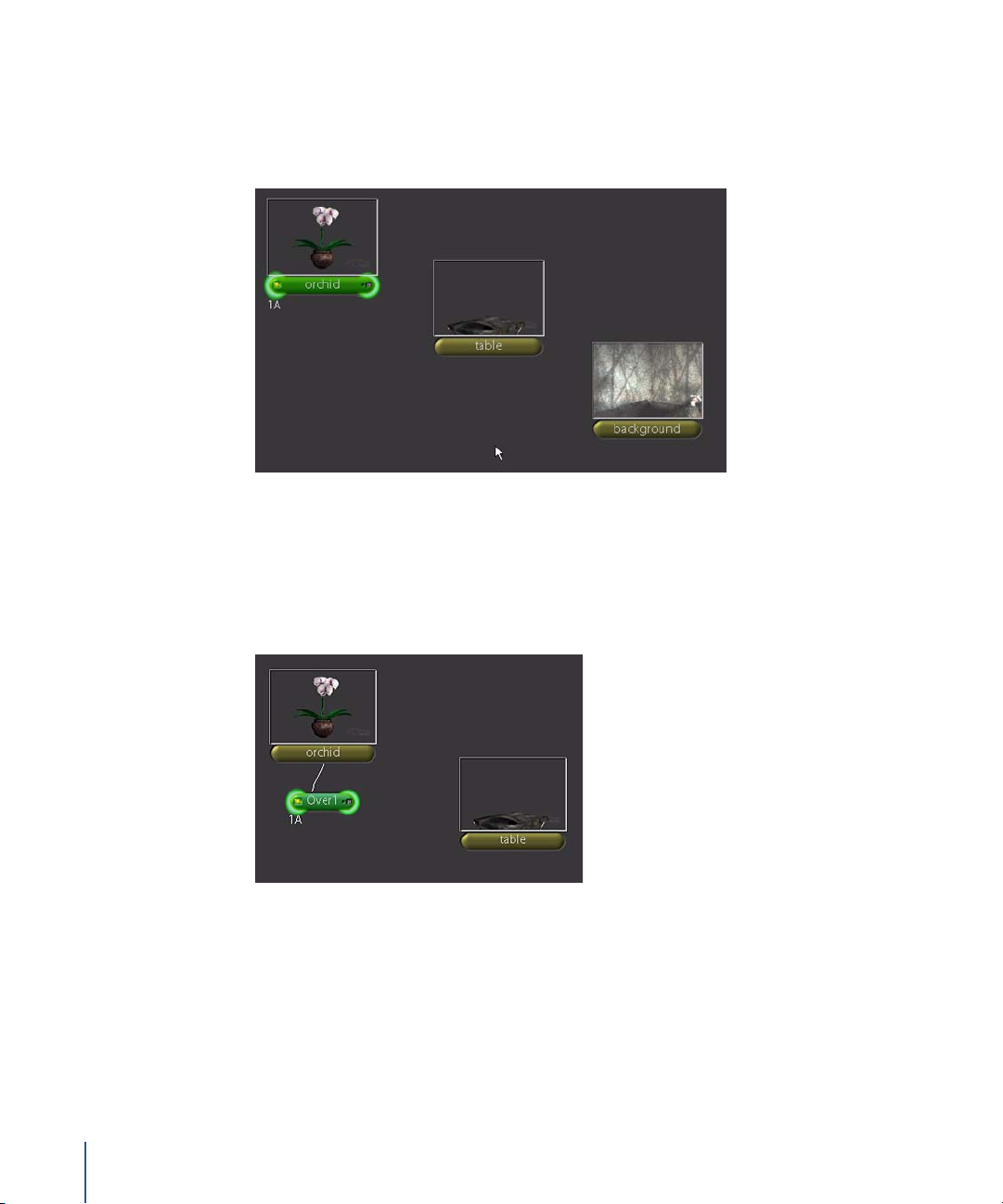
Now that you know how to navigate through the Shake interface, you’re ready to
composite the elements. Finally! Arrange the FileIn nodes like this, in the order that you
want to composite them:
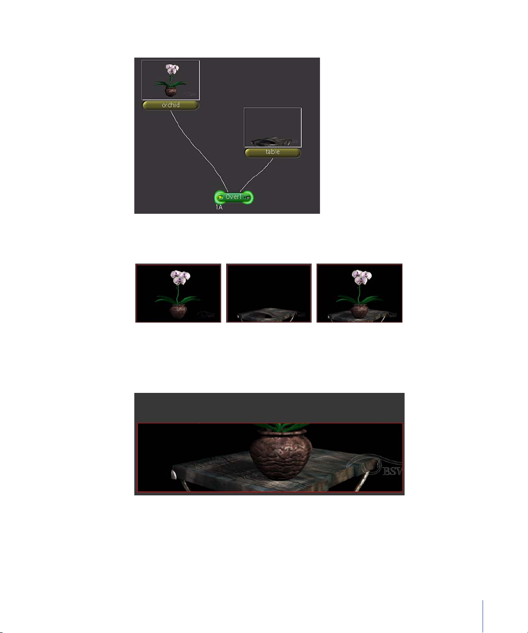
To begin the composite:
1 Click the orchid node to select it.
2 In the Tool tabs, click the Layer tab, then click Over.
Over1 is automatically attached to the orchid, because that node was selected when
you added the new node.
The Over1 node has two inputs on the top of the node, although you won’t see them
until you place the pointer over the node. The orchid node is attached to the first input.
3 Move the Over1 node down a little. Then, drag the second input from the top of the
Over1 node to the bottom of the table node to connect the two nodes.
26 Chapter 1 Shake Basics
Page 27
You can also drag from the bottom of table to the second input on Over1.
Information flows downward in the Node View like a stream—the image data is passed
from the orchid and table nodes, and fed into the Over1 node to create the composite.
orchid node
table node
Over1 node
What happened? The top half of the image is gone. We’ll fix this in a minute—and
explain what it means.
Chapter 1 Shake Basics 27
Page 28
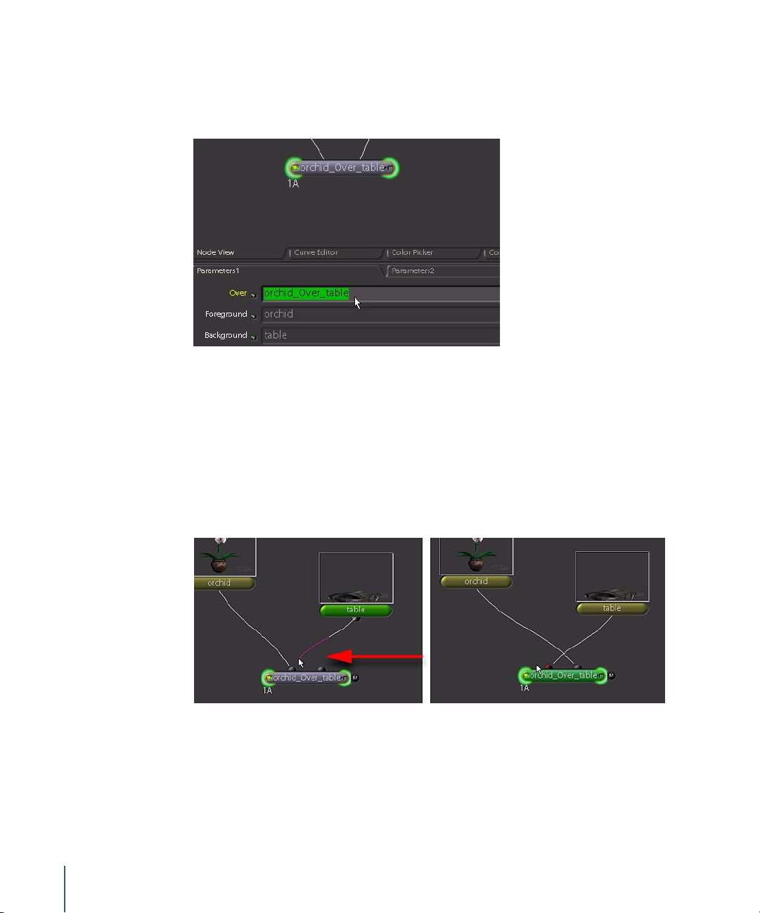
Look in the Parameters tab, where the Over1 parameters now appear. The first
parameter is the same for all nodes: the name of the node. By default, Shake assigns a
generic name and appends a number to it, which allows each node to have a unique
name. You can type a different name in the text field and make it more descriptive.
4 Click in the first parameter field for Over1, and type “orchid_Over_table.”
The new name reflects the compositing logic for the node: “Input 1 is Over Input 2.” If
you switch the inputs, then the compositing order is reversed.
Note: When you move the pointer over the line—called a noodle—that connects two
nodes, the end changes color (magenta = lower end, yellow=upper end) to show that
you can drag or delete the connection.
5 Drag the lower end of the table noodle to the first input on orchid_Over_table.
28 Chapter 1 Shake Basics
Page 29
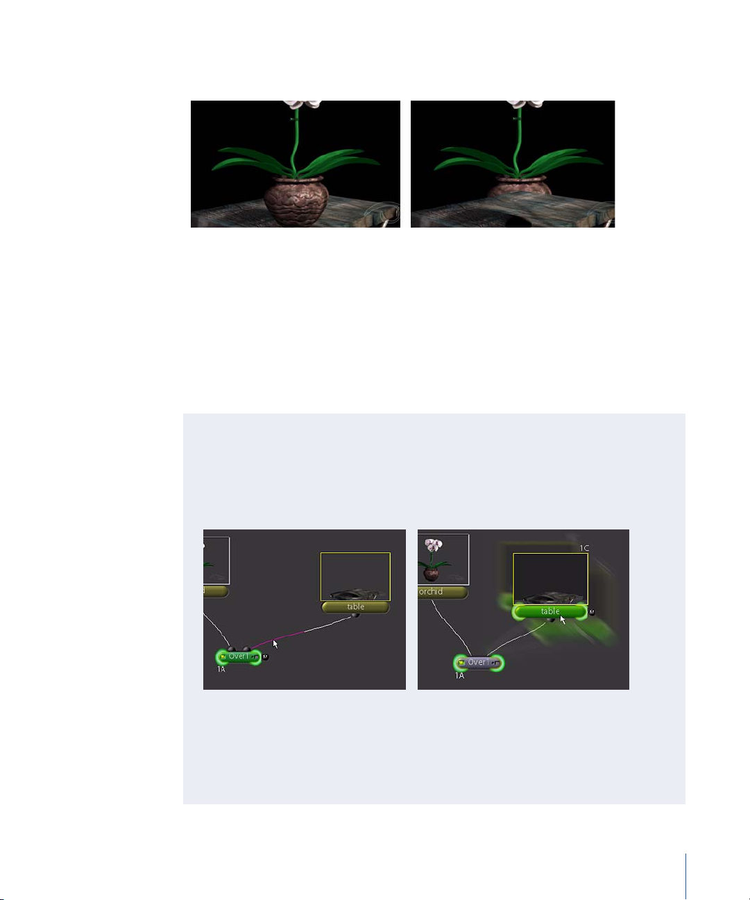
The node logic is switched, which completely changes the result of the composite. The
orchid now appears behind the table when it should be on top.
6 Switch the inputs again (or press Command-Z or Control-Z to undo your previous
operation). The orchid image appears over the table image again.
As you work with the different layer nodes, you’ll find they have distinct methods for
creating the layered output. The Over node, for example, follows the logic of “Input 1 is
Over Input 2”—or more specifically, “The pixel values of Input 1 are placed Over the
pixel values of Input 2.” As you’ll soon see, other layer nodes use different logic to
create their output, such as “The pixel values of Input 1 are Added to the pixel values of
Input 2” or “The pixel values of Input 1 are Multiplied by the pixel values of Input 2.”
Breaking Connections Between Nodes
Use one of the following methods when you need to break a connection between
nodes:
• Move the pointer over one end of a noodle and press Delete (Mac OS X) or
Backspace (IRIX and Linux). You can also Control-click the noodle.
• Select a node and press E on your keyboard to extract the node—and
appropriately break all its connections. If necessary, you can always drag any node
back over a noodle to insert it again.
• Take advantage of Shake’s namesake and quickly drag and shake a node to break
its connection.
Chapter 1 Shake Basics 29
Page 30
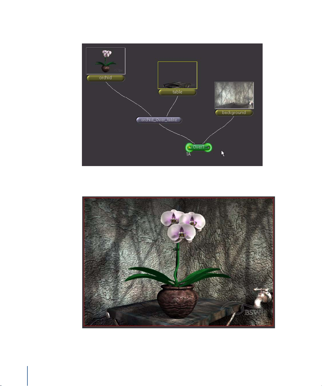
7 In the Node View, select the orchid_Over_table node and add one more Over node. Use
the following illustration as a guide to connect the background element.
The result appears in the Viewer. We can thank the folks at Big Sister's Watching, NY for
their impressive work. But it didn’t always look like this, did it?
30 Chapter 1 Shake Basics
Page 31

If you were paying attention when you connected images to that first Over node, your
composite looked like this for a brief period:
Although everything turned out fine, it’s important to understand why Shake clipped
the image—it’s a feature, honest—and how this can help you. This, and other
mysteries, are explained in the next section.
Setting Resolution
Shake supports an Infinite Workspace, which means you can dynamically change
resolution during the compositing process and Shake will handle it. For example, you
can simultaneously output an HD image and a 601 video image and your compositing
process will be independent of any specific resolution—yes, even independent of the
resolution you set up in the Globals tab. You can change resolution at any place, as
many times as you need, along the node tree.
Resolution = 660 x 170
Resolution = 720 x 486
Resolution = 720 x 486
Chapter 1 Shake Basics 31
Page 32

Setting Resolution in a Composite
There are several ways to set the resolution for your composite:
• Composite elements so that one of the elements is already set to the resolution
you want to use. Then, use the clipMode parameter in the layer node (Over, lAdd,
lMult, and so on) to indicate which image you want to pass as the resolution for the
next node in the tree.
• From the Transform tab, use the Fit, Resize, or Zoom node to scale your images.
• From the Transform tab, use the Crop, Viewport, or Window node to change the size
(that is, resolution) of the workspace you’re passing down the node tree. These
nodes do not resize the image, but instead reset the framing of the image.
Notice that none of these methods involve the Globals tab, where you’d expect all
global project settings to be defined. The resolution set in the Globals tab does
determine the initial resolution Shake-generated elements such as rotoshapes, ramps
and gradients, but it does not change the resolution of images read into the script
from outside source files.
So, what does this have to do with the clipped image in our composite? What you saw
earlier was the result of Shake’s automatic method for adjusting resolution according to
the images you’re using. Take another look at your composite to see how this
information applies.
To set the resolution with the clipMode parameter:
1 Move the mouse pointer over the orchid node.
In the Info field at the bottom of the screen, you’ll see that this image has a resolution
of 720 x 486.
2 Now click the left side of the table node to load the image into the Viewer.
This image is 660 x 170 pixels—different dimensions than the orchid image. When you
use a layer node, Shake assumes you want to pass the resolution of the second image
(called the “background” image) to the next node in the tree. In this case, Shake took
the resolution of the table image and passed it downstream. Unfortunately, the smaller
resolution also framed out part of the orchid image. Don’t fret; you can change which
input controls the resolution.
3 Double-click the orchid_Over_table node in the Node View to simultaneously view that
node and load its parameters.
In the Parameters tab, you’ll see setting called clipMode. When clipMode is set to
“foreground,” the resolution of the first image is used; when set to “background,” the
resolution of the second image is used.
32 Chapter 1 Shake Basics
Page 33

4 To ensure that the resolution is 720 x 486 pixels, set clipMode to foreground.
The image is no longer clipped.
5 Double-click the Over1 node to view the full composite again.
In this situation, the Over1 node restores the orchid image, even without the clipMode
fix. This is because orchid isn’t truly clipped. The Shake Infinite Workspace ensures that
images are never permanently clipped due to framing. If an image is clipped at one
point in the node tree, the image data will still be there when the resolution is
increased further down the tree.
Filtering and Masking
All the elements in this project are in sharp focus. Softening a portion of the
background will add an illusion of depth to the shot. You don’t have a “soft-focus”
version of the background, but you can create one with a Blur node and an RGrad
mask. Add the blur effect first, then mask it to create a depth-of-focus effect.
To add the blur effect to the background:
1 Select the background node, then insert a Filter–Blur node.
2 Click the left side of the Over1 node to load it into the Viewer.
3 Click the right side of the Blur1 node to load it into the Parameters tab.
4 In the Blur1 parameters, drag the slider beneath the first pixels value field (the slider
appears when you move the pointer over it), and set the blur pixels to 20.
Not bad, but the angle of the background walls means the sides which are closer to the
camera should gradually draw into focus. You can fix this with a mask.
Chapter 1 Shake Basics 33
Page 34

5 Using the following illustration as a guide, add a new Image–RGrad node and attach it
to the side mask port on the Blur1 node.
The blur effect is now controlled by the pixel values in the RGrad1 alpha channel.
Lighter pixels allow the effect to be applied to the background image. Darker pixels
block the effect.
Tuning Parameters
So now you’ve got your basic composite. The mask needs some fine tuning to improve
the effect, and this will give you some practice with the Parameter controls. Node
controls may include parameters for numerical entry, sliders to set values, color
controls, and Viewer overlays (onscreen transform controls) for interactive control. The
RGrad1 node has all these parameters and controls.
Note: If you are using a stylus, open the Globals tab, then turn on virtualSliderMode in
the guiSettings subtree. This assists you with the virtual slider. You should also assign
one of the stylus buttons as the right-mouse button.
To adjust the placement and shape of the gradient:
1 Click the left side of the Over1 node to load it into the Viewer.
34 Chapter 1 Shake Basics
Page 35

2 Click the right side of the RGrad1 node to load it into the Parameters tab.
3 In the RGrad1 Parameters tab, set radius to 100, and falloffRadius to 400.
4 Display the subtree for center, then change the xCenter value to 360.
5 Change aspectRatio to 1.5.
The result will look similar to this:
The overlay circles and crosshairs are interactive transform controls that allow you to
make adjustments in the Viewer.
6 Drag the inner and outer circles to change the radius and falloffRadius, then drag the
crosshairs to move the center of the gradient, adjusting the appearance of focal range.
Chapter 1 Shake Basics 35
Page 36

In the illustration below, the radius is set to 312 and the falloffRadius is set to 370.
It’s looking better, but there’s still a big difference between the sharp area and the
blurred area. Adjust the gradient colors to fix this, then set the Blur1 node to use a color
channel from RGrad1 as the mask, instead of the alpha channel. When you change the
gradient colors and substitute the alpha channel with one of the color channels, you
can adjust the opacity of the mask and its effect on the blur filter.
7 Click the right side of the Blur1 node to load its parameters, expand the Mask subtree,
then set maskChannel to R (red).
It doesn’t matter which of the three color channels you specify. You just need to choose
one of the color channels to use as the mask.
8 Now click the right side of the RGrad1 node to load it back into the Parameters tab.
9 Click the centerColor control.
The Color Picker opens.
36 Chapter 1 Shake Basics
Page 37
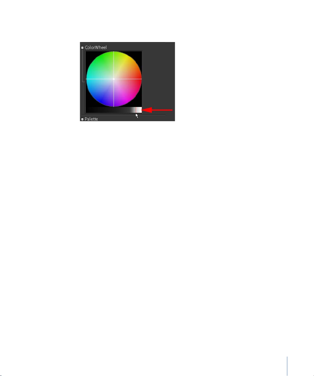
10 Drag in the luminance bar, under the ColorWheel, until you see a softer focus for the
background in the Viewer.
Working With Layer Nodes
This example includes other elements for soft shadows and lighting. Instead of the Over
node, you’ll use Layer–lMult and Layer–Screen to blend these elements into the
composite you created in the previous exercise.
To load the lighting and shadow images:
1 Add an Image–FileIn node to the node tree.
2 In the File Browser, navigate to the $HOME/nreal/Tutorial_Media/Tutorial_01/images/
lighting directory, select lighting.30-59@.exr, then click Next (or press the Space bar).
3 Move up one directory, then open the shadows directory, select shadows.30-59@.exr,
then click OK.
Chapter 1 Shake Basics 37
Page 38

4 Arrange the nodes as shown in the illustration below.
Composite the soft shadows first.
5 Select the Over1 node, then add a Layer–lMult node to the tree.
6 Connect the shadows image to the second input.
Rather than place one image over another, the lMult node multiplies pixel values
together. For this reason, it doesn’t matter that the shadows image is connected to the
second input. The shadow image is multiplied into the existing image, not placed on
top of it. Here is the result:
Now you have some nice soft shadows in the nooks and crannies, but they might be a
little too dark. You can adjust the amount that the first input is multiplied by the
second input.
38 Chapter 1 Shake Basics
Page 39

7 In the lMult1 parameters, drag the percent slider to set it to 65.
Next, composite the lighting pass.
8 Select the lMult1 node and insert a Layer–Screen node.
9 Connect the lighting node to the second input of the Screen1 node.
Not again! In the Viewer, you’ll see a clipped image, similar to what you saw earlier in
this tutorial.
Move the pointer over the lighting node and you’ll see it has a resolution of 360 x 243.
This resolution is obviously not the desired output.
Chapter 1 Shake Basics 39
Page 40

10 Drag the noodle from the second input on Screen1 to the first input.
That fixed the clipping situation but didn’t change the size of the lighting image to
match the rest of the composite. You could re-render this element at the full resolution,
but who has time to do that? Alternatively, you can resize it with a transform node (just
don’t tell your CG supervisor).
Transforming an Image
Most of the transform nodes display onscreen controls that let you interactively scale,
move, and even distort the image. In this example, use the Move2D node to resize and
position the lighting image.
You can speed up interactive tranforms by changing the Viewer update method. Press
and hold the “always” button in the upper-right corner of the Node View, then choose
“release” from the pop-up menu.
This tells Shake to update the Viewer only after you’ve released the mouse button.
To scale and position the lighting image:
1 Select the lighting node, then insert a Transform–Move2D node.
2 Locate the scale parameter in the Parameters tab, then, type “2” in the first value field
(xScale).
40 Chapter 1 Shake Basics
Page 41

Or, in the Viewer, drag a corner of the Move2D transform control until the scale
parameter is set to 2.
The size is right, but the image is not in the correct position.
3 Drag the triangles or the crosshairs to position the image to match the rest of the
composite.
4 Open the pan subtree in the Move2D1 parameters, then adjust the values so that xPan
= 181 and yPan = 12 3.
The lighting pass should now be in the right place.
Fading an Element
You’re almost done. The final step in this exercise—before rendering the animation—is
to adjust the lighting pass. Right now, it’s a little washed-out, so you’ll use a Fade node
to control its effect on the rest of the image. Fade operates on all channels in the
image, including the alpha channel. This time you’ll use the shortcut menu to insert the
required node.
To adjust the opacity of an image:
1 Click the Color tab to display the color command nodes.
Chapter 1 Shake Basics 41
Page 42
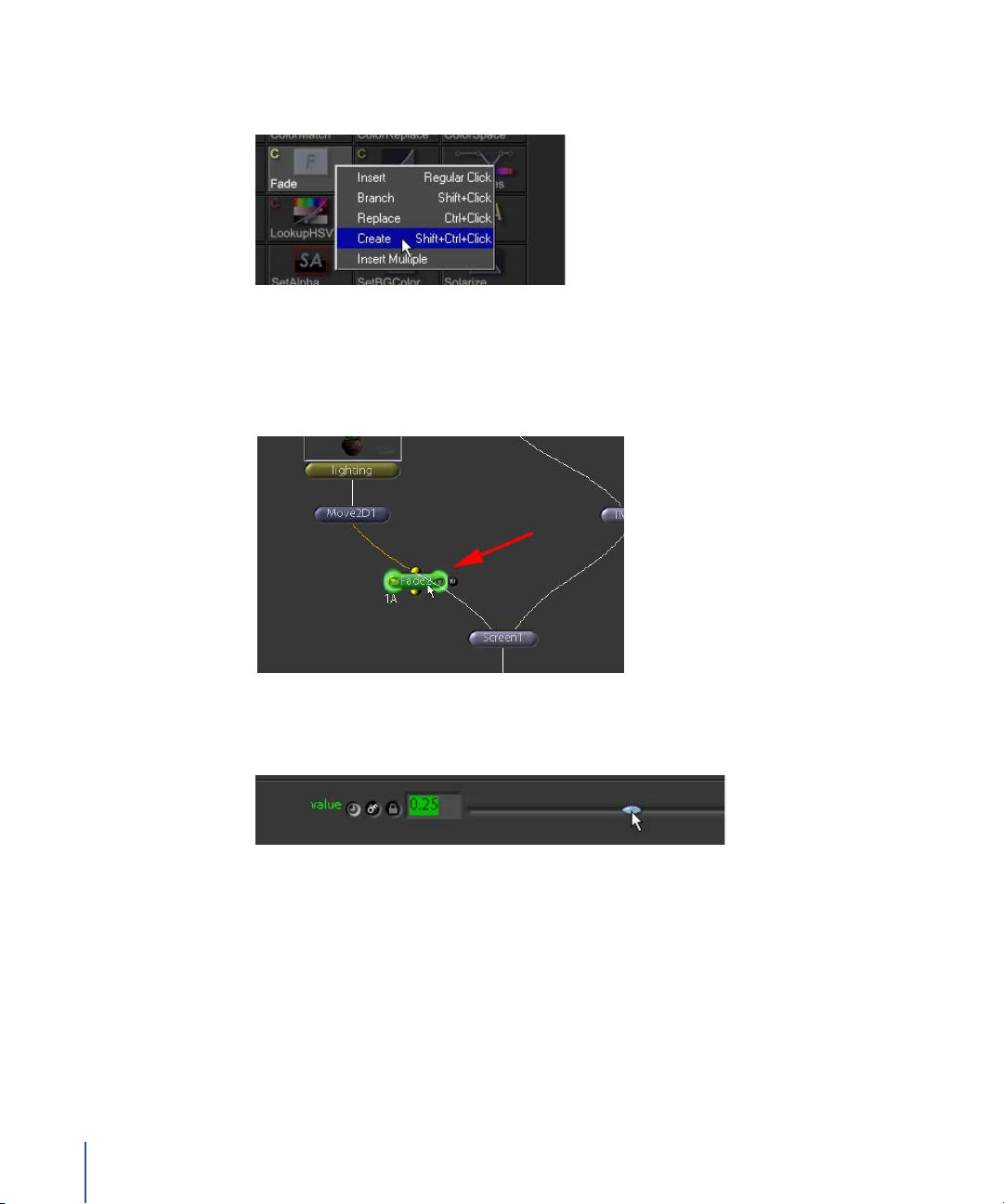
2 Right-click Fade, then choose Create from the shortcut menu (or, you can click Fade
while holding down the Control and Shift keys).
This inserts a new Fade1 node that is not connected to any existing nodes.
3 Drag Fade1 over the connection between the Move2D1 and the Screen1 nodes. When
the inputs turn yellow, release the mouse button and Fade1 is inserted between the
two nodes.
4 In the Fade1 parameters, drag the value slider to 0.25.
This reduces the opacity of the lighting pass to 25 percent.
42 Chapter 1 Shake Basics
Page 43

The finished image will look similar to this:
Rendering a Sequence
When you’re ready to create the final images for your composite, you insert at least one
FileOut node at the place in the node tree where you want to render. This is often at the
bottom of the node tree, because this is where the final result is composited. However,
you can place as many FileOut nodes as you need to output from different places along
the tree, and send rendered output to multiple directories and formats.
To add a FileOut node:
1 In the Globals tab, click the Auto button to ensure that the timeRange is set to 1-30.
2 Attach an Image–FileOut node to Over1.
The File Browser opens.
3 In the File Browser, navigate to the desired directory.
4 In the File Name text field at the bottom of the browser, type “comp.#.sgi” as the file
name.
Chapter 1 Shake Basics 43
Page 44

About File Names
When you enter the file name for render output, the name should include a
combination of the following:
• The name of the file.
• A frame-numbering symbol for image sequences. When you render to an image
sequence, include a frame numbering symbol—either @ or #. A single @ is an
unpadded number—that is, 1, 2, 3, 4. A single # is 4-place padding—that is, 0001,
0002, 0003. Either symbol used multiple times indicates that many places of
padding, that is, @@@@@ is 00001, 00002, 00003.
• A .mov extension for QuickTime files. When you render to a QuickTime file, omit the
frame-numbering symbol and append the file name with the .mov extension. The
QuickTime format options appear in the FileOut parameters.
• A file format extension, such as .cin, .sgi, .jpg, .iff, and so on, is required.
For example:
Enter comp.#.sgi as your file name, and the rendered images are written as
comp.0001.sgi, comp.0002.sgi, comp.0003.sgi, and so on.
5 Once you have entered your file name settings in the File Browser, click OK.
To save the script:
1 Click the Save button in the upper-right corner of the Shake window (or press
Commmand-S or Control-S).
Because this is the first time you are saving the script, the Save Script window appears.
Next time you click Save, Shake updates the existing file with the latest changes.
44 Chapter 1 Shake Basics
Page 45

2 In the File Name text field, type “orchid.shk” as the name for the script, then click OK.
Note: To Save As, use Command-Shift-S or Control-Shift-S, or choose File > Save As.
To render files to disk:
1 From the menu bar, choose Render > Render FileOut Nodes.
The Render window appears.
Note: You can also right-click in the Node View, then choose Render > Render FileOut
Nodes from the shortcut menu.
In the Render window, you can enter a new time range, proxy scale, quality level,
motion blur, and the number of CPUs to use for the render. To render all FileOut nodes,
enable All in the renderFileOuts parameter.
To render only active FileOuts, enable Selected. You can also select a FileOut node after
the Render Parameters window is opened.
2 Click the Auto button to copy the time range from the Globals tab.
3 Click Render.
The images are rendered to disk, and a 320 x 243 snapshot view of the current frame is
displayed. The snapshot is always 320 x 243, regardless of input resolution, and only
shows the currently rendering frame.
Batch Rendering in a Shell
You can choose to render on the command line. Click the Save button at the top of the
Node View (or press Command-Shift-S or Control-Shift-S) to save the script. If you have
not yet saved the script, you are prompted for a script name; otherwise it writes over
what you had before.
Note: If you are working in a shell, you have usually set environment variables. For
more information, see “Environment Variables for Shake” in Chapter 14 of the Shake 4
User Manual.
1 Save your script and hide or quit Shake.
Chapter 1 Shake Basics 45
Page 46

2 Open Terminal and navigate to the directory where your orchid.shk script is saved.
3 Type:
shake -exec orchid.shk -v
Note: In OS X, if you do not have environment variables set for Shake, you must type
the full Shake path, for example:
/Applications/Shake/shake.app/Contents/MacOS/shake -exec orchid.shk -v
Usually, you set your environment variables to use the shake command with a lowercase “s.” For more information, see “Environment Variables for Shake” in Chapter 14 of
the Shake 4 User Manual.
On a Linux or IRIX system, type the following (the Shake command begins with a
lower-case “s”):
shake -exec orchid.shk -v
The -v means “verbose,” so the render status is displayed. For more information on the
command line, see Appendix B, “The Shake Command-Line Manual,” in the Shake 4 User
Manual.
4 To override the time range, use the -t option:
shake -exec orchid.shk -v -t 10-20
or
shake -exec orchid.shk -v -t 1-56x2
The above command renders every other frame.
46 Chapter 1 Shake Basics
Page 47

2 Intermediate Skills
This tutorial shows how to optimize your workflow with
the SetDOD node, and how to use the Shake Time View,
and the Curve Editor. You will also learn how to add
motion blur, how to color-match the elements in a
composite, and how to import Photoshop files as layers
in a composite.
2
Tutorial Summary
• Inserting nodes into a tree
• Using the Time View
• Grouping nodes and using SetDOD
• Creating motion blur
• Importing Photoshop files
• Keyframe animation and the Curve Editor
• Color corrrection
47
Page 48

To explore the topics of this tutorial, you’ll work with images from the Beanfield music
video Tides, kindly provided by the artist, Maximilian Graenitz.
Inserting Nodes Into a Tree
Before you continue with the tutorial, take a moment to review different ways to insert
and manage items in the Node View. The illustrations show a generic “node,” but you
can try these with any node from the Tool tabs.
• Insert, Method 1: Select the parent node, then click a node button in the Tool tabs.
• Insert, Method 2: Drag an existing node onto a noodle to insert it between
connected nodes.
• Branch: Select the parent node, then Shift-click a node button in the Tool tabs.
48 Tutorial 2 Intermediate Skills
Page 49

• Replace: Select the node you want to replace, then Control-click a node button in
the Tool tabs.
• Insert Unconnected: Control-Shift-click a node button in the Tool tabs. The new node
appears in the Node View unconnected to any other node.
• Extract: Select the node, then press E (for Extract). The node is disconnected from the
tree.
Tutorial 2 Intermediate Skills 49
Page 50

• Delete: Select the nodes by clicking, Shift-clicking or dragging a selection box, then
press Delete.
• Delete Connection: Control-click the noodle, or move the pointer over one end of the
noodle (it turns magenta at the bottom or yellow at the top), then press Delete.
Grouping Nodes and Using SetDOD
When your script includes many elements, two features can help you control the
organization and rendering of the nodes: the SetDOD node and the Groups command.
SetDOD provides a powerful optimization step that reduces rendering time, I/O activity,
and memory use. The Groups commands lets you combine two or more nodes into a
“gr ouped” node in the tree.
50 Tutorial 2 Intermediate Skills
Page 51

Optimizing With SetDOD
A DOD (Domain of Definition) is a rectangular region around an element that defines
the part of the image you want to include in render calculations. Usually, the DOD is
used to exclude empty image areas from render calculations.
Before SetDOD: Whole image area is
calculated and rendered.
After SetDOD: Only image area inside DOD
is calculated and rendered.
But you can also use SetDOD to crop out parts of an image that you don’t want to
include in your composition. Give it a try.
To open the little_guys.shk script:
1 Click the Load button at the top of the Node View.
2 In the File Browser, navigate to the $HOME/nreal/Tutorial_Media/Tutorial_02/scripts
directory.
3 Select the little_guys.shk file and click OK.
Tutorial 2 Intermediate Skills 51
Page 52

To add the SetDOD node:
1 In the Node View, select the mitosis node.
2 Insert a Transform–SetDOD node.
3 Make sure the onscreen controls are enabled for the Viewer.
4 Drag the DOD corners or edges in the Viewer to frame the “little guy” character.
52 Tutorial 2 Intermediate Skills
Page 53

This tells Shake to calculate only the image information within the DOD boundaries.
The rest of the image is ignored, thereby reducing memory usage, I/O activity, and
processing time, both upstream and downstream in the node tree.
5 Click the Flipbook button in the Viewer shelf to create a preview of the image with the
DOD applied.
When you play back the preview (press the period key), you’ll see that the DOD crops
some of the animation as the clip plays. To fix this, make an adjustment to the border.
To adjust the SetDOD border:
1 Load the SetDOD1 node into the Parameters tab.
2 Change the border setting to these values: left = 240, right = 600, bottom = 65, and
top = 512.
This allows enough border space to include all the animation from the clip.
Note: You can further optimize rendering for each frame by animating the DOD
borders at different places along the duration of the clip. Don’t do this for the current
tutorial—it will cause problems later in the example—but keep it in mind for future
reference.
The SetDOD node will save you a small amount of render time for each frame. As the
number of elements in your composite increases, so does the potential render time.
Additional SetDOD nodes can dramatically optimize a complex composite.
Grouping Nodes
Next you’ll use Shake’s Groups commands to combine the mitosis, SetDOD1, and
Move2D1 nodes as one node in the tree. This will help you copy and manage these
elements in the script.
Tutorial 2 Intermediate Skills 53
Page 54

To group the mitosis, setDOD1, and Move2D1 nodes:
1 In Node View, drag to select the mitosis, setDOD1, and Move2D1 nodes.
2 Right-click in the Node View, then choose Groups > Group Selected Nodes from the
shortcut menu.
The new Group1 node appears in the Node View.
3 In the Parameters tab, rename the node to “mitosis_group.”
54 Tutorial 2 Intermediate Skills
Page 55

4 Click the Expand button on the mitosis_group node to show its contents.
When a group is expanded, you can select and edit the nodes inside the group.
5 Click the Expand button again hide its contents.
Using the Time View
In the next example, you’ll make a few adjustments to the mitosis clip in the Time View,
where you can modifiy the location and duration of clips.
To display the Time View:
m
Click the Time View tab (on the right side of the Tool tabs, underneath the Viewer),
then then press the Space bar to expand this pane to full screen size.
Tutorial 2 Intermediate Skills 55
Page 56

Each image node and layer node in the composite is represented by a horizontal bar,
lined up with the frames in the Time Bar.
Tips for Working in the Time View
• The Time View shares similiar functions with the Node View. You can select nodes
in both windows. You can view nodes, load parameters, and ignore nodes by
clicking the controls on the bars in the Time View.
Load into
the Viewer
• Turn on the Select Group button to load only the active nodes into the Time View.
• To scale the Time View, press Command or Control while holding down the middle
Load into the
Parameters tab
Ignore node
Load into
the Viewer
Load into the
Parameters tab
Press I to ignore.
mouse button, and drag left or right.
• To pan the Time View, hold down the middle mouse button and drag left or right.
The mitosis clip starts at frame 1 and ends at frame 50. The towers bar is a still image
with no start or end frame—notice the “infinity” (∞) symbols at each end of the towers
bar. The Over1 bar also has the “infinity” symbols at each end. You change the length of
a clip by dragging its timing handles, located on either end of the bar.
Note: The mitosis_group node does not appear in the Time View because groups do
not have In/Out points in time. The Time View shows only images, image sequences,
movie files, and layer nodes.
To modify the duration of the mitosis clip:
1 Drag the right timing handle to the left until its number reads 35.
2 Press the Space bar again to restore the original size of the Time View.
You’ve just shortened the length of the clip. The new start/end frames also appear in
the mitosis Parameters tab.
56 Tutorial 2 Intermediate Skills
Page 57
To load the mitosis node into the Parameters tab, do one of the following:
m
In the Node View click the right side of the mitosis node.
m
In the Time Bar, click the parameters indicator on the mitosis bar.
The mitosis parameters appear in the Parameters tab.
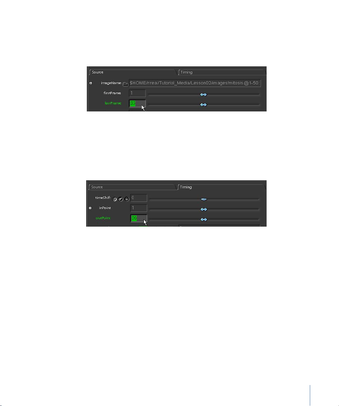
Under the Source subtab , the firstFrame parameter is set to 1 and the lastFrame
parameter is set to 35. These are the source frames read from the image sequence
on disk.
Click the Timing subtab and you’ll see how the clip lines up with the Time Bar frames.
The inPoint is set to 1 and the outPoint is set to 36, which is one frame after the last
frame in your clip.
Suppose you want to change where the clip begins in the Time Bar, but you don’t want
to change the number of frames used from the clip.
Tutorial 2 Intermediate Skills 57
Page 58

To modify the clip’s position in the Time Bar:
m
In the Time View, drag the middle of the mitosis bar to the right.
The entire clip moves to the right.
Frame numbers where the In/Out
points line up in the Time Bar
Start (In point) and end (Out point)
frames for the sequence or clip
As you drag the mitosis bar, dark blue numbers appear outside the ends of the bar to
show where the start and end frames of the clip line up with the Time Bar frames.
Check the Timing subtab, and you’ll see the new time shift indicated there also.
The first parameter, timeShift, shows the difference, if any, between the frame numbers
of the clip and the frame numbers in the Time Bar. Positive numbers shift the clip
forward and negative numbers shift the clip backward.
The next two parameters, inPoint and outPoint, correspond to the dark blue numbers
you saw while dragging the clip in the Time View.
To restore the mitosis clip to its original Source and Timing parameters:
1 In the Source subtab, set firstFrame to 1 and lastFrame to 50.
2 In the Timing subtab, set timeShift to 0, inPoint to 1, and outPoint to 51.
Continuing with this lesson, after extending the length of the mitosis clip, you’ll create
several copies of it, then slide those copies in the Time Bar to stagger their start and
end frames. This ensures that the clips are not synchronized, lending the illusion of
multiple “little guys” spawning independently.
58 Tutorial 2 Intermediate Skills
Page 59

To extend the length of the mitosis clip:
1 In the Time View, press the Control or Command key and drag the right timing handle
of the mitosis clip until the Out point (dark blue number) reads 101.
Pressing the Control or Command key while dragging a timing handle breaks the
relationship between the disk clip and the duration of the clip in the composite. The
newly extended area of the clip is calculated in one of several repeat modes. The
default repeat mode—represented by a blue bar—is a freeze frame: Shake fills the
expanded time range in the clip with a freeze frame of the last frame in the clip.
Note: When you drag a timing handle without pressing Control or Command, you extend
the length of the sequence in the composite without modifying the extended area. In
other words, if you drag a timing handle beyond the number of frames in the source clip,
the output after the last frame in the source clip will consist of empty black frames.
For the purposes of this example, change the repeat mode from a freeze frame to a
loop (or mirror) playback.
2 In the Timing subtab of the mitosis parameters, set the outMode control to Mirror.
The inMode and outMode parameters tell Shake what to do with a clip that is
extended beyond the number of frames available from the image sequence on disk. In
this example, the animation wasn’t designed to loop, so use the Mirror outMode to
repeat the frames in reverse order. In all, there are five repeat modes:
Button Mode Result
Black No frames repeat.
Freeze Last (or first) frame is held and repeated indefinitely.
Repeat The entire clip repeats, starting at the first frame.
Tutorial 2 Intermediate Skills 59
Page 60
Button Mode Result
Mirror The clip repeats, first in reverse order, and then forward,
indefinitely. To provide a smooth transition, the first frame does
not repeat between the loops.
InclusiveMirror The entire clip repeats, first in reverse order, and then forward,
indefinitely.
You now have everything set up for the first original copy of our “little guys” element.
The next step is to make a copy of all the nodes for this element, and paste four or
more copies to populate the composite.
To make copies of the elements:
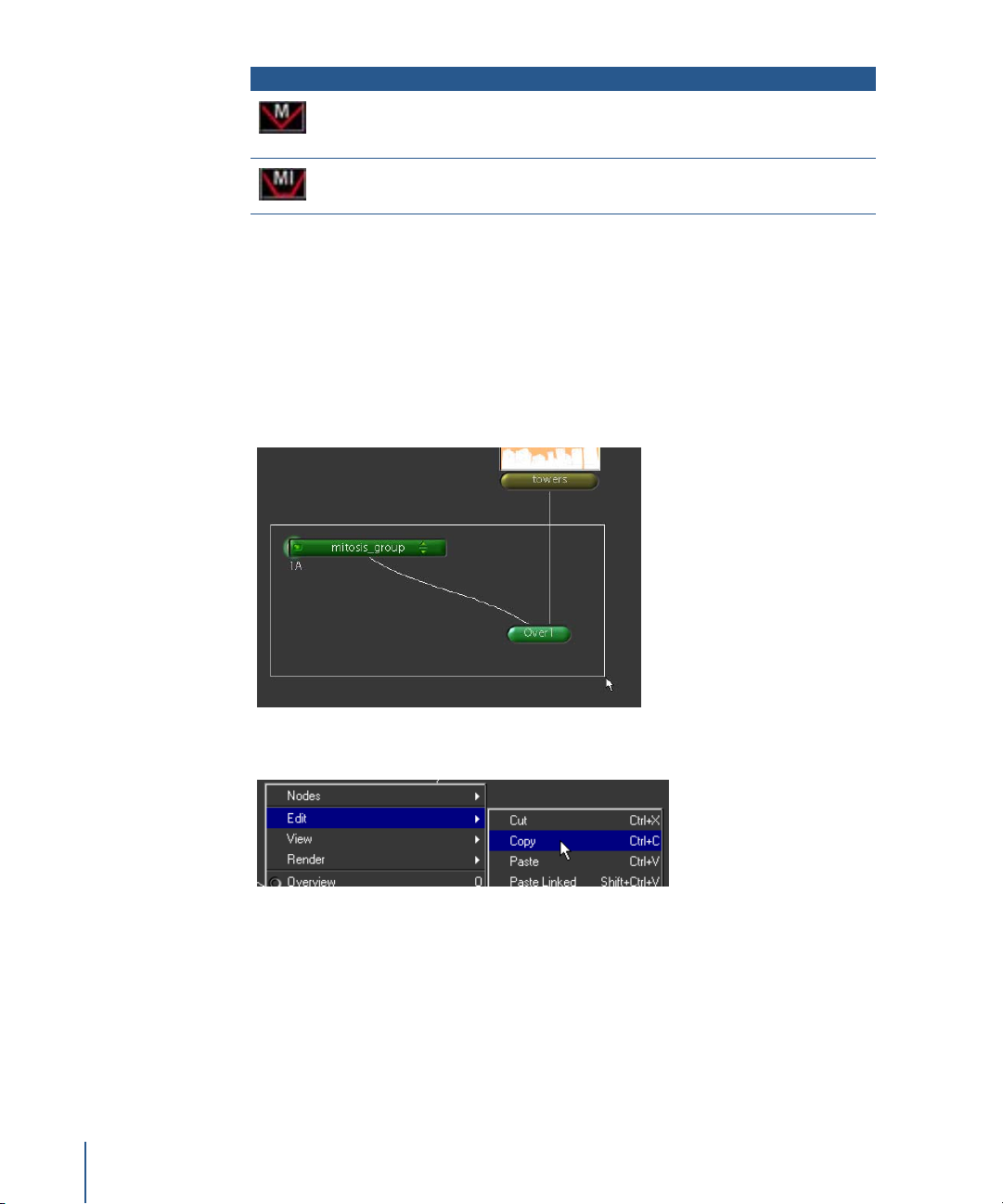
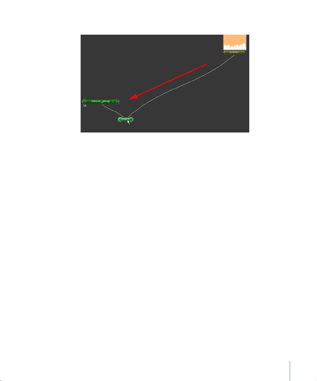
1 In the Node View, select both the mitosis_group node and the Over1 node.
Note: To collapse the mitosis_group node, click the Expand/Collapse button on the
right side of the group header.
2 Right-click in the Node View, then choose Edit > Copy from the shortcut menu.
60 Tutorial 2 Intermediate Skills
Page 61
3 Drag the selected nodes to the left in the Node View to make room for the copies.
4 Right-click in the Node View, then choose Edit > Paste from the shortcut menu (or
press Control-V) to place the first copy.
5 Repeat Step 4 to paste at least three additional copies.
Tutorial 2 Intermediate Skills 61
Page 62
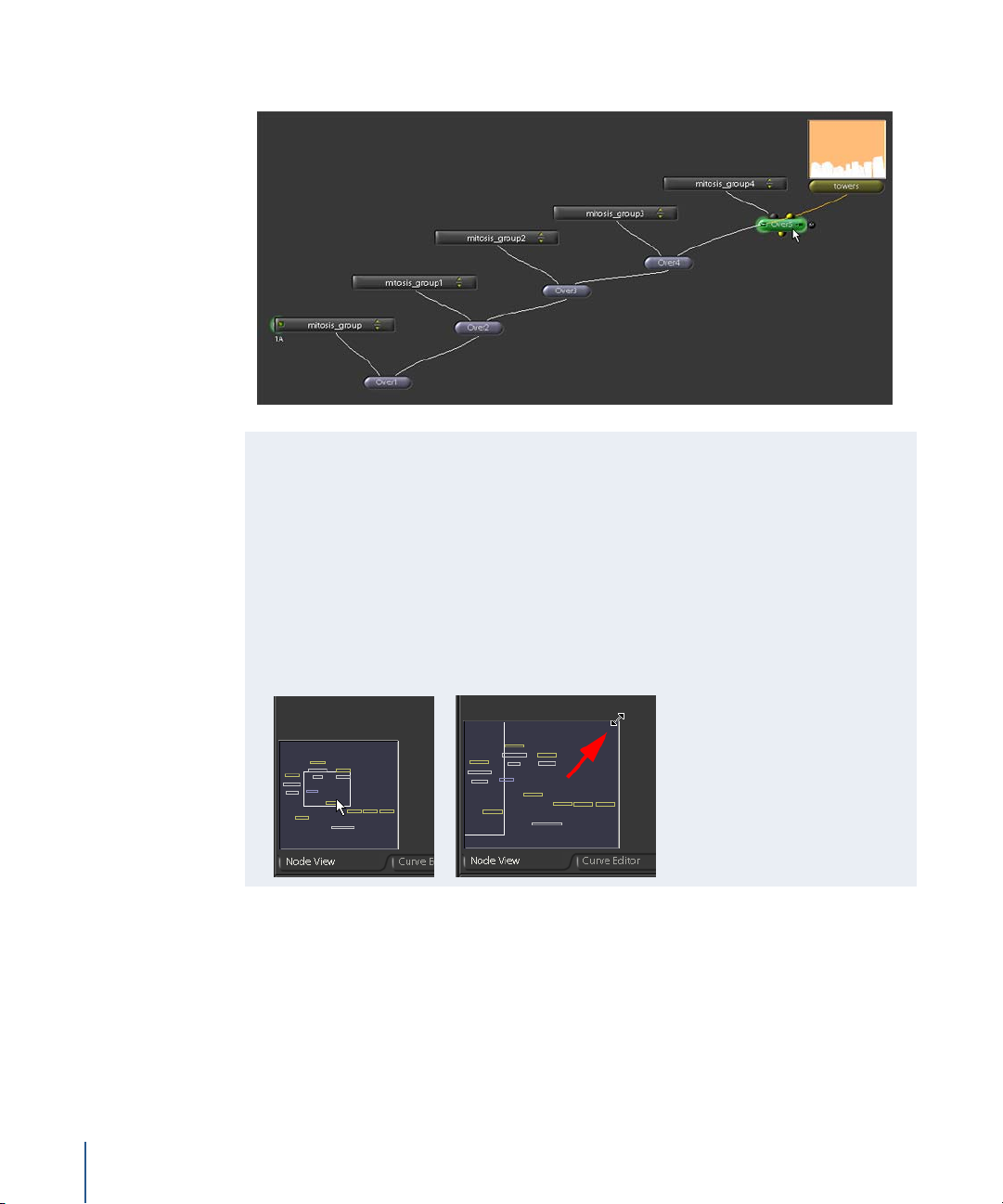
6 Using the illustration below as a guide, connect the copies to the rest of the node tree.
Tips for Navigating in the Node View
The Node View can get a little unwieldy when you add a large number of nodes to
your script. Here are some tips to help you work more efficiently. With the pointer
over the Node View:
• Press the plus key (+) to zoom in. Press the minus key (–) to zoom out.
• Press F on your keyboard to frame all selected nodes. If none is selected, press F to
frame the entire node tree.
• Press O to display the node overview. You can drag inside the overview frame to pan
to different areas of the node tree, and also drag the overview border to resize it.
So you have your copies. But they all occupy the same position in the Viewer. Use all
those Move2D nodes to position the “little guys” at different points in the Viewer.
62 Tutorial 2 Intermediate Skills
Page 63
To position the “little guys”:
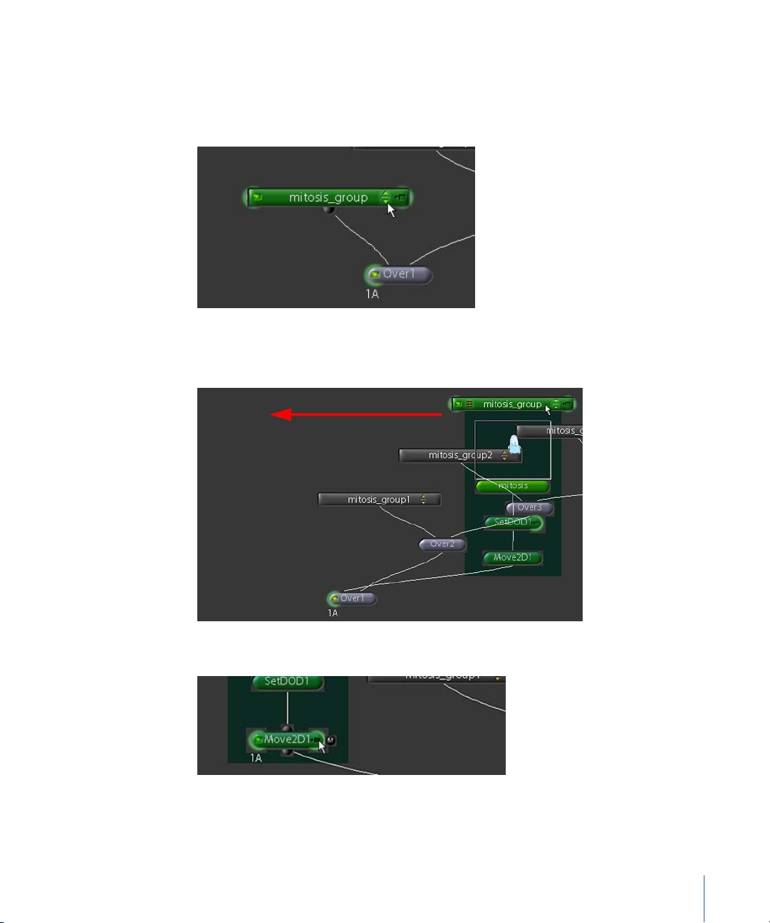
1 Load the leftmost Over1 node into the Viewer.
2 Click the Expand/Collapse button on the leftmost mitosis_group node to show its
contents.
The group window expands (and jumps to its original paste position).
3 Drag the group header to the left to see its contents more clearly.
4 Click the right side of the Move2D1 node to load its parameters into the Parameters tab.
Keep that Over1 node, at the bottom of the node tree, displayed in the Viewer.
Tutorial 2 Intermediate Skills 63
Page 64

5 Drag a corner of the Move2D onscreen controls (the box overlay) to change the size of
the element.
6 Drag the top and side triangles to position the element within the frame.
It doesn’t matter where you place the element or how big it is. Just resize it and move
it away from the center.
7 Click the Expand/Collapse button on the mitosis_group node to hide its contents.
8 Repeat the previous steps to size and place all the copies of the mitosis element.
Now you need to stagger the copies in the Time View, to start the animation for each
copy at different places in the time line.
To stagger the mitosis clips in the Time View:
1 Set the Out frame in the Time Bar to 50.
2 Open the Time View and drag each copy of the mitosis clip—but not the original—so
that the bars are randomly staggered, like this:
This causes the animation of each copy to start at a unique spot along the Time Bar.
64 Tutorial 2 Intermediate Skills
Page 65

3 Double-click the Over1 node (the last Over node at the bottom of the node tree), to see
the results of the composite.
When you are finished, your composite should look similar to this:
4 Click the Flipbook button to preview the finished composite.
That’s it for this example. In the next project, you’ll see how to add motion blur to
elements in a composite.
Tutorial 2 Intermediate Skills 65
Page 66

Creating Motion Blur
The motion blur feature lets you simulate the effect you see with moving objects in real
photography. Shake relies on changes in position or scaling created with one of the
Transform nodes—Move2D, Move3D, CornerPin, and so on—to generate motion blur for
an element.
In this example, you’ll open the “magic carpet” script and add motion blur to one of the
elements.
To open the “magic carpet” script:
1 Click the Load button at the top of the Node View, browse to the $HOME/nreal/
Tutorial_Media/Tutorial_02/scripts directory, then open the magic_carpet.shk script.
66 Tutorial 2 Intermediate Skills
Page 67

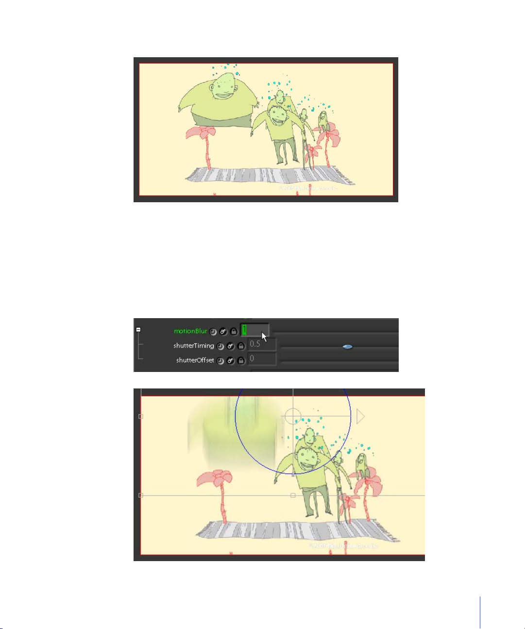
2 Click the Globals tab and expand the motionBlur subtree.
Note: The Move2D, Move3D, CornerPin, CameraShake, Pan, Rotate, Scale, Stabilize, and
MatchMove transform nodes also have motion blur parameters.
The motion blur parameter has no effect until you apply an animated transformation to
an element. Shake creates the motion blur by tracking each pixel through the
transformation.
Motion Blur Parameters
• motionBlur: Controls motion blur quality. When set to 0, the blur effect is turned
off. When set to 1 or greater, the blur effect is of high quality. Lower the motionBlur
value to 0.5 for acceptable quality, or to 0.1 for draft previewing.
• shutterTiming: Specifies the fraction of the frame exposed for the motion blur. The
default setting of 0.5 indicates that only half of the frame of movement is exposed.
This mimics the shutter exposure of 178 degrees out of 360 for a real film camera,
rounded up to 0.5. You can also enter 178/360 to be exact. To match a video camera
with a shutter setting of 1/300, enter 1/300 in the shutterTiming parameter. This
resolves the setting to 0.0033 and creates a tiny amount of motion blur. When
shutterTiming is set to 0, motion blur is disabled. If set to 1, the entire frame is
calculated. You can also set this number higher than 1 to calculate later movement
into the current frame.
• shutterOffset Specifies an offset from the current frame, from which the blur effect
should be calculated. The default of 0 calculates motion blur starting with the
current frame. If, for example, you set the shutterOffset to –1, blur is calculated
from the previous frame. This can be useful when adjusting motion blur for
rotoshapes.
Tutorial 2 Intermediate Skills 67
Page 68
To create a transformation for motion blur:
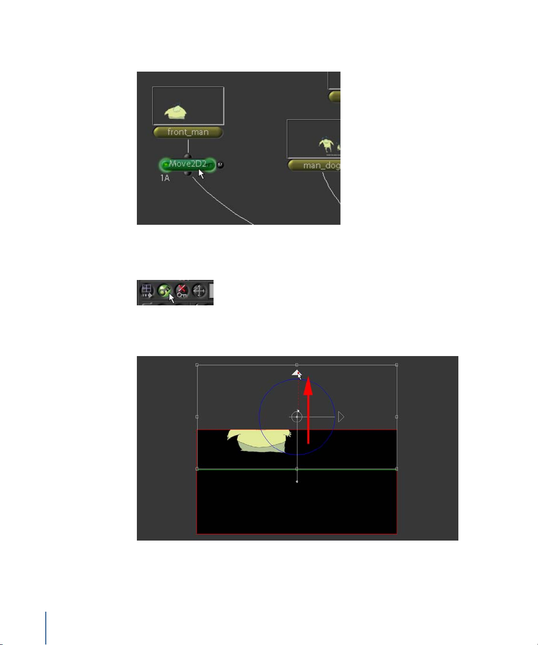
1 Select the front_man node, then insert a Transform–Move2D node.
2 Move the playhead to frame 25 in the Time Bar.
3 Enable the Autokey button in the Viewer shelf.
4 Move the playhead to frame 30, then drag the onscreen transform control up until the
“front man” character moves out of view.
This animated transformation between frames 25 and 30 creates the movement Shake
needs to generate motion blur.
68 Tutorial 2 Intermediate Skills
Page 69
5 Click the right side of the Over4 node to load the final output into the Viewer.
No motion blur, right? You still need to specify the motion blur settings. (See “Motion
Blur Parameters” on page 67 to review the Shake motion blur settings.)
To activate the motion blur:
1 Scroll to the bottom of the Move2D1 parameters and expand the motionBlur subtree.
2 Set motionBlur to 1.
You should now see some motion blur action.
Tutorial 2 Intermediate Skills 69
Page 70

3 Set motionBlur to 0.25 to lower the blur quality.
4 Enter a few different settings for shutterTiming to test the effect of this parameter.
shutterTiming = 0.5
shutterTiming = 1.5
shutterTiming = 0.15
Time to settle on one of these.
5 Set shutterTiming to 0.35.
6 Test the effect of shutterOffset by entering different values for this parameter.
shutterOffset = 0.5
shutterOffset = –2
shutterOffset = 1.25
7 Reset shutterOffset to 0.
8 Click the Flipbook button to generate a preview of the completed composite.
70 Tutorial 2 Intermediate Skills
Page 71
Note: Generally, it’s better to define motion blur settings for individual transform
nodes. You can set motionBlur to 0 in the Globals tab to temporarily turn off all motion
blur calculations, and thereby speed up your workflow. Just remember to reset the
global motionBlur parameter to 1 when you need to preview the effect in the Viewer or
render final output.
The first two motion blur parameters in the Globals tab are multipliers of the motion
blur settings for the individual transform nodes. Entering 0 for global motionBlur, for
example, internally multiplies all the motionBlur settings in the transform nodes by 0,
which effectively disables all motion blur. On the other hand, entering a global
motionBlur setting of 2 doubles the values. Set the global motionBlur to 1 to restore
motionBlur settings on the individual nodes.
Importing Photoshop Files
Shake handles several different file formats. The FileIn node is the standard method for
“reading in” (importing) images into the Node View. However, Photoshop files are
handled a bit differently. You can use the FileIn node to read in Photoshop files, but if
your file has multiple layers, it’s better to use the import feature designed specifically
for Photoshop. Give it a try.
First you’ll use the FileIn node to read in a Photoshop file. Then you’ll compare the
results to the Photoshop import feature.
To import a Photoshop file using the FileIn node:
1 Create a new script by choosing New Script from the File menu.
2 Add an Image–FileIn node.
3 Browse to the $HOME/nreal/Tutorial_Media/Tutorial_02/images/field_wawas directory,
then double-click the background.psd file.
Shake inserts the Photoshop file as a single image.
Tutorial 2 Intermediate Skills 71
Page 72
Now use the Photoshop import feature to read in the same file.
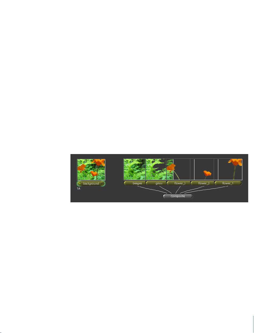
To import a Photoshop file using the Import command:
1 Choose Import Photoshop File from the File menu.
2 Browse to the same directory as before ($HOME/nreal/Tutorial_Media/Tutorial_02/
images/field_wawas) and double-click the background.psd file.
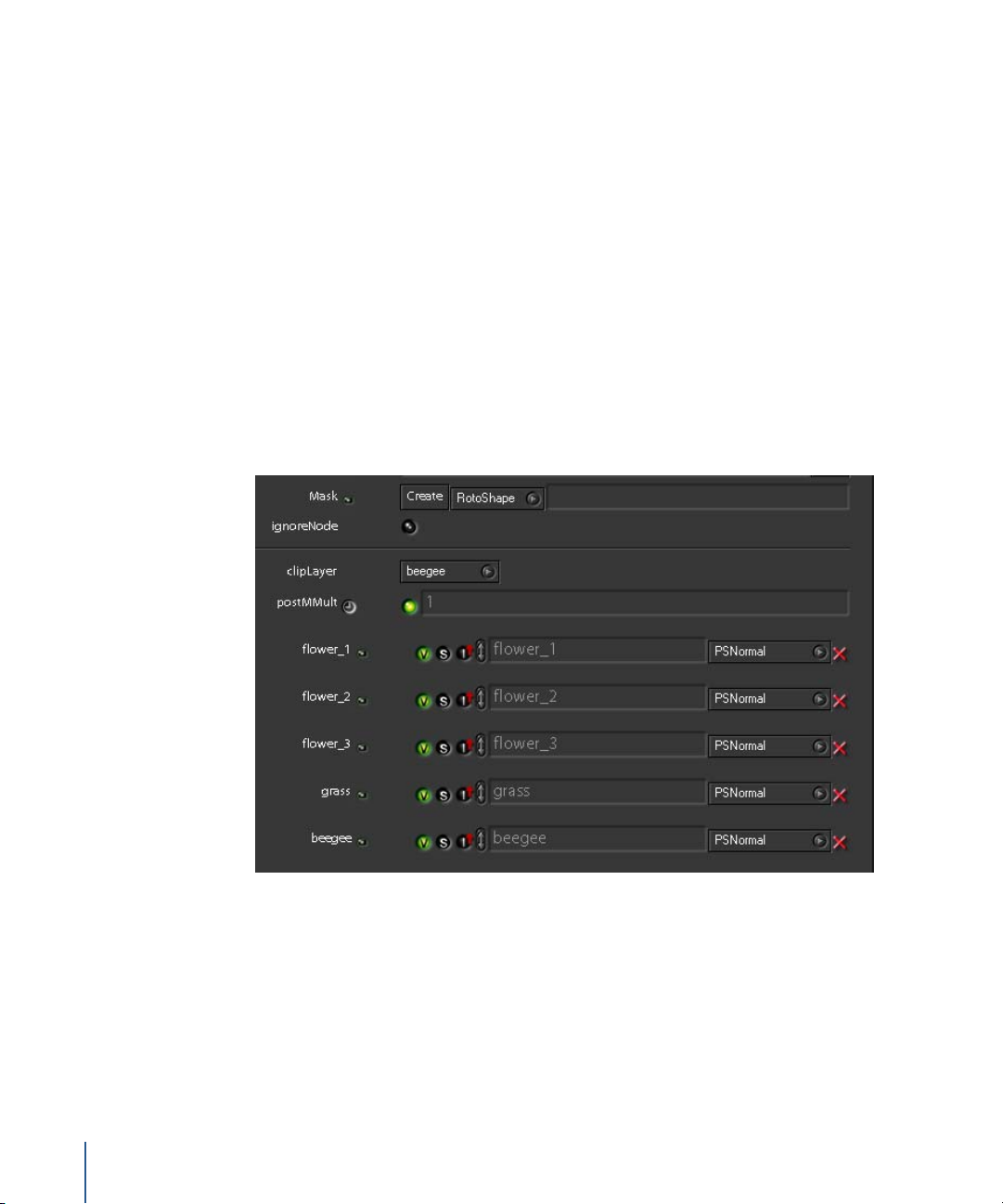
This time, Shake organizes each Photoshop layer in the file as a separate image and
inserts a Composite node to create the same result as the background node that you
inserted.
Note: The Composite node in this example is actually a Layer–Multilayer node, inserted
with the Photoshop import command and renamed “Composite.”
What’s so great about this? Now you can expand the node tree and insert other
elements between the Photoshop layers. You can also edit the layers in the original
Photoshop file, and the changes will be updated in your Shake script.
3 Double-click the Composite node to load it into the Viewer and Parameters tab.
72 Tutorial 2 Intermediate Skills
Page 73

As you can see, each Photoshop layer has its own set of parameters inside the
Composite node. The clipLayer parameter controls the output resolution of the
Composite node.
Name (layer)
Solo layer
Layer visibility
Ignore layers above
Drag this control to change the position of
the layer in the composite.
Blend mode
Delete layer
Now let’s add some new elements and incorporate them into the composite.
4 In Node View, delete the background node.
5 Insert an Image–FileIn node, then browse to the $HOME/nreal/Tutorial_Media/
Tutorial_02/images/field_wawas directory.
6 Shift-click wawa1.1-30@.tif, wawa2.1-30@.tif, and wawa3.1-30@.tif to select these image
sequences, then click OK.
7 Arrange the nodes as shown in the following illustration.
Tutorial 2 Intermediate Skills 73
Page 74

Zoom in on the Composite node (press Command-middle-click or Control-middle-click
and drag right). You’ll see the plus sign (+) on the top-right edge of the Composite
node.
Drag any noodle to the plus sign and you’ll add new inputs—in this case, new layers—
to the node.
8 Drag a noodle from the wawa1 node to the + sign on the Composite node.
9 Load the Composite parameters.
Note that a new layer is stacked on top of the existing layers in the Photoshop file.
Move it behind all the “flower” layers.
10 Using the Reposition control for the wawa1 layer, drag that layer down below the
flower_3 layer.
11 Drag noodles from both the wawa2 and wawa3 nodes to the plus sign on the
Composite node.
74 Tutorial 2 Intermediate Skills
Page 75

12 In the Parameters tab, use the Reposition controls to drag the wawa2 and wawa3 layers
below the grass layer.
13 Click the Save button at the top of the Node View, and save the script as
field_wawas.shk.
Keyframe Animation and the Curve Editor
This section continues with the script you created in the previous section. You’ll add
animation to create motion that doesn’t exist in the original image sequences. Then,
you’ll use the Curve Editor to adjust the animation keyframes.
To animate the “wawa” characters:
1 In the Globals tab, enter 1-30 as the timeRange, then click the Home button in the
Viewer playback controls to match the Time Bar to the global time range.
2 Select the wawa2 node and insert a Transform–Move2D node.
Before completing the next step, make sure the playhead is set to frame 1.
Tutorial 2 Intermediate Skills 75
Page 76

In the Move2D1 Parameters tab, click the AutoKey button next to the pan parameters.
3 Move the playhead to frame 30, then, using the onscreen transform controls, drag the
wawa2 character to the right edge of the frame.
4 Again, using the tranform controls of the Move2D1 node, adjust the vertical position of
the wawa2 element at frames 10, 20, and 30 to create a “bouncing” movement. It
should look like the character is hopping through the grass.
No need to be precise. The result is two animation curves, visible in the Curve Editor.
The first curve (xPan) makes the “wawa” move from left to right. The second curve
(yPan) creates the up-and-down movement to make the character look like it’s
hopping. In a moment, you’ll edit the animation in the Curve Editor.
5 In the Move2D1 Parameters tab, click the small clock button next to the pan
parameters.
This is the Load Curve button. A red checkmark over the button indicates that the
Move2D1 pan parameter is loaded in the Curve Editor. Usually the checkmark appears
whenever you activate AutoKey for a parameter. In this case, it didn’t because there are
more parameters in the pan subtree.
76 Tutorial 2 Intermediate Skills
Page 77
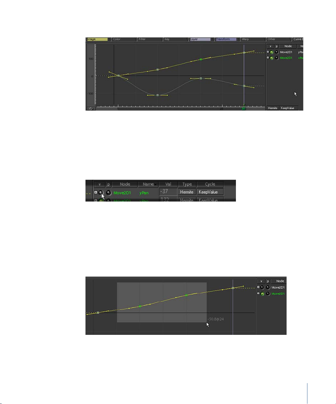
6 Click the Curve Editor 2 tab (in the Tool tabs) to view the animation curves.
Note: To expand the window, position the pointer in the Curve Editor and press the
Space bar. Press the Space bar again to reset the Curve Editor window.
Here you’ll see the curves for the two pan parameters that you animated: xPan and
yPan. The points on the curves indicate the places where you set keyframes in the Time
Bar. To the right of the curves, you’ll see the individual curve channels.
7 Click the Visibility button for the yPan parameter to hide this curve.
Notice that the xPan curve basically follows a linear path. Yours might look different,
but in the example shown here, the xPan was animated so that wawa2 moves from left
to right as it “hops.” As you can see, the xPan curve actually has more keyframes than it
needs to create that linear movement.
8 Drag a selection box around all the keyframes—excluding the first and last
keyframes—on the xPan curve. Then, press Delete (near the Page Up/Page Down keys)
or Backspace to remove the extra keyframes.
9 Click the Visibility button for the yPan parameter to display this curve again.
Tutorial 2 Intermediate Skills 77
Page 78
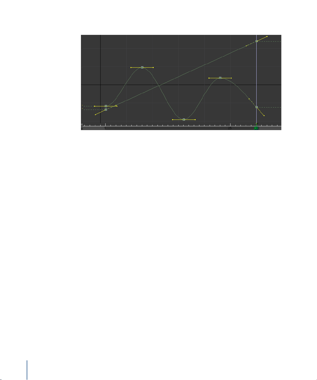
10 Drag the yPan keyframes until your curves look similar to the following illustration.
Now make use of what you’ve already learned about motion blur.
11 In the Move2D1 parameters, expand the motionBlur subtree, set motionBlur to 1, and
shutterTiming to 1.25.
If you move the playhead, you’ll see motion blur on the wawa2 character. Note that the
blur effect disappears at frame 30. You can create an offset to fix this.
12 In the motionBlur subtree, set shutterOffset to –1.
If you need practice on animation and the Curve Editor, add another Move2D node for
wawa3 and animate that, as well.
78 Tutorial 2 Intermediate Skills
Page 79
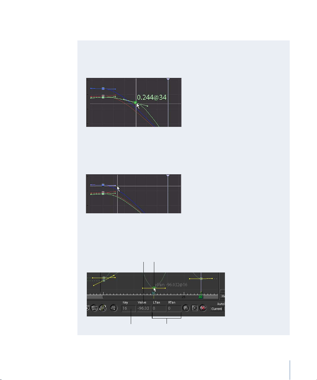
13 Before you continue, click the Save button at the top of the Node View to save the
changes you’ve made.
Curve Editing Tips
• To move a keyframe, click the keyframe and drag.
• To insert a keyframe, Shift-click a curve segment. You can also enter a value at the
desired frame in the Val field of the Curve Editor.
• To remove a keyframe, select the keyframe and press Delete (near the Page Up/
Page Down keys) or Backspace.
• To adjust the tangents, click and drag a tangent handle.
A “flatter” tangent creates a smoother ease-in/ease-out effect for the animation at
that point in the curve.
• To break the tangents of a curve, Control-click a tangent handle.
• To restore broken tangents, Shift-click a tangent handle.
• To perform a precise edit on a keyframe, select its point on the curve, then
manually enter the frame number and value in the Key and Value fields at the
bottom of the Curve Editor.
Numeric value of keyframe
Location of keyframe
on Time Bar
Tutorial 2 Intermediate Skills 79
Selected keyframe
Tangent angles
Page 80
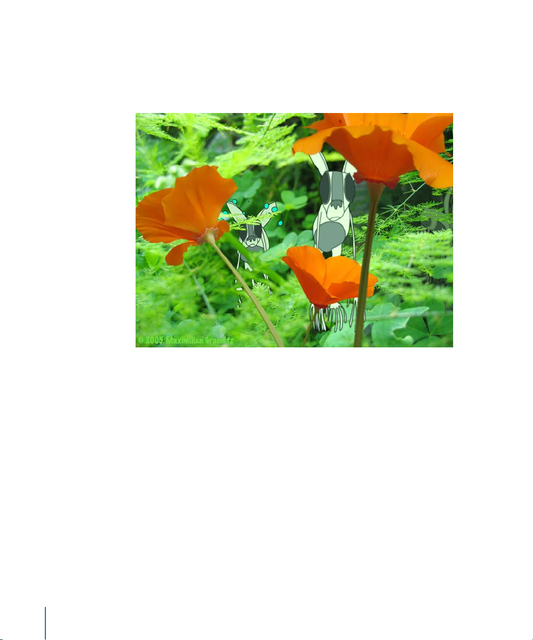
Color Correction
You’ve got a nice composite with the animated “wawas.” Now it ‘s time to blend the
elements using color correction. First, you need to match the base colors of the
animation to the photographic layers. Second, you want to vary the luminosity of the
characters to mimic the lighting from the background.
Many color-correction nodes reflect Shake’s command-line heritage by applying color
corrections as single-function mathematical operations—Add, Brightness, Gamma, and
Multiply all perform single-function color corrections. Other nodes work as master
color-correction nodes by applying the combined result of multiple color functions. The
ColorMatch node falls in the latter category.
In this next example, you’ll use the ColorMatch node to match the base colors of one of
the animated characters to the photographic background. Then you’ll apply clones of
this color correction to the other characters, so that any changes you make to the
original ColorMatch node will ripple down to the other characters.
To color correct wawa1:
1 In Node View, select the wawa1 node.
2 Insert a Color–ColorMatch node (choose ColorMatch from the Color command tab).
80 Tutorial 2 Intermediate Skills
Page 81

A ColorMatch node appears after the wawa1 node.
ColorMatch1 is already loaded into parameters, but we need to see the result of the
composite to match our character to the background.
3 Click the left end of the Composite node to load its output into the Viewer.
In the ColorMatch parameters, you’ll see controls that let you specify the low, mid, and
high colors of the image (the “Source”) that you want to color correct. Typically, the low
color is black or the darkest color in the image. The high color is white or the lightest
color. The mid color is neutral gray or a value between the low and high values you’ve
selected.
Choosing the low, mid, and high values from the
source image you want to color correct
Tutorial 2 Intermediate Skills 81
Page 82

The ColorMatch Parameters tab also contains controls for colors you want to match (the
“Dest” or destination colors), which are also low, mid, and high. When you first insert
the ColorMatch node, the color selections for Source and Dest will be the same.
Choosing the low, mid, and high values from the
destination image that the source image will match
As you adjust the Source and Dest colors, the ColorMatch node will color correct the
source image to conform to similar colors in the destination image. This is a good way
to match the base colors of your animated elements to the background.
4 Zoom into the Viewer (press + a few times) to get a closer view of the wawa1 character.
5 In the ColorMatch parameters, click the lowSource color control and click the black
outline of the “wawa.”
Try to get the darkest pixel you can find on the outline.
6 Click to select the highSource color control, then drag inside of the white area of
wawa’s ear.
82 Tutorial 2 Intermediate Skills
Page 83

7 Click to select the midSource color control, then drag inside a gray area between the
wawa’s nose. This should be the most neutral area between the low and high values
you’ve selected.
You won’t see a difference in the Viewer because you haven’t specified the Destination
colors yet. As you continue with the next steps, notice how the image changes with
each of your selections.
8 Click to select the lowDest color control, then drag inside the darkest area you see in
the background.
9 Click to select the highDest color control, then drag inside the brightest area from the
background.
Tutorial 2 Intermediate Skills 83
Page 84

10 Click the midDest color control, then drag inside a neutral area or a midrange value
between the lightest and darkest areas in the background.
Your ColorMatch settings will look similar to this:
11 Click the Home button in the Viewer shelf to see the entire image.
84 Tutorial 2 Intermediate Skills
Page 85

The image doesn’t look quite matched. So let’s make adjustments to the color
selections. You can do this with precise channel sliders, found in the subtrees beneath
the color controls. You can also drag over the color control while pressing keystroke
modifiers to focus adjustments to specific values.
To adjust color selections with subtree sliders:
1 Expand the first subtree beneath the lowDest color control.
R channel value
B channel value
B channel value
Beneath the color control, you’ll see a slider with several buttons—R, G, B, H, S, V, T, M,
and L. The slider acts like a master control to adjust a specific color property: red (R),
green (G), blue (B), hue (H), saturation (S), value (V), temperature (T), magenta (M), or
luminosity (L).
2 Make sure the Luminosity (L) button is selected, then move the slider left to change the
Luminosity setting to 0.1.
3 Expand the first and second subtrees under highDest, to show the channel sliders
beneath the property buttons. Set the rHighD slider to 0.85, and the gHighD slider
to 0.98.
This is definitely an improvement, and adds little more contrast, but the green color is
still too strong. Let’s adjust the midrange color. This time, instead of the color sliders,
you’ll use the keystroke modifiers.
Tutorial 2 Intermediate Skills 85
Page 86
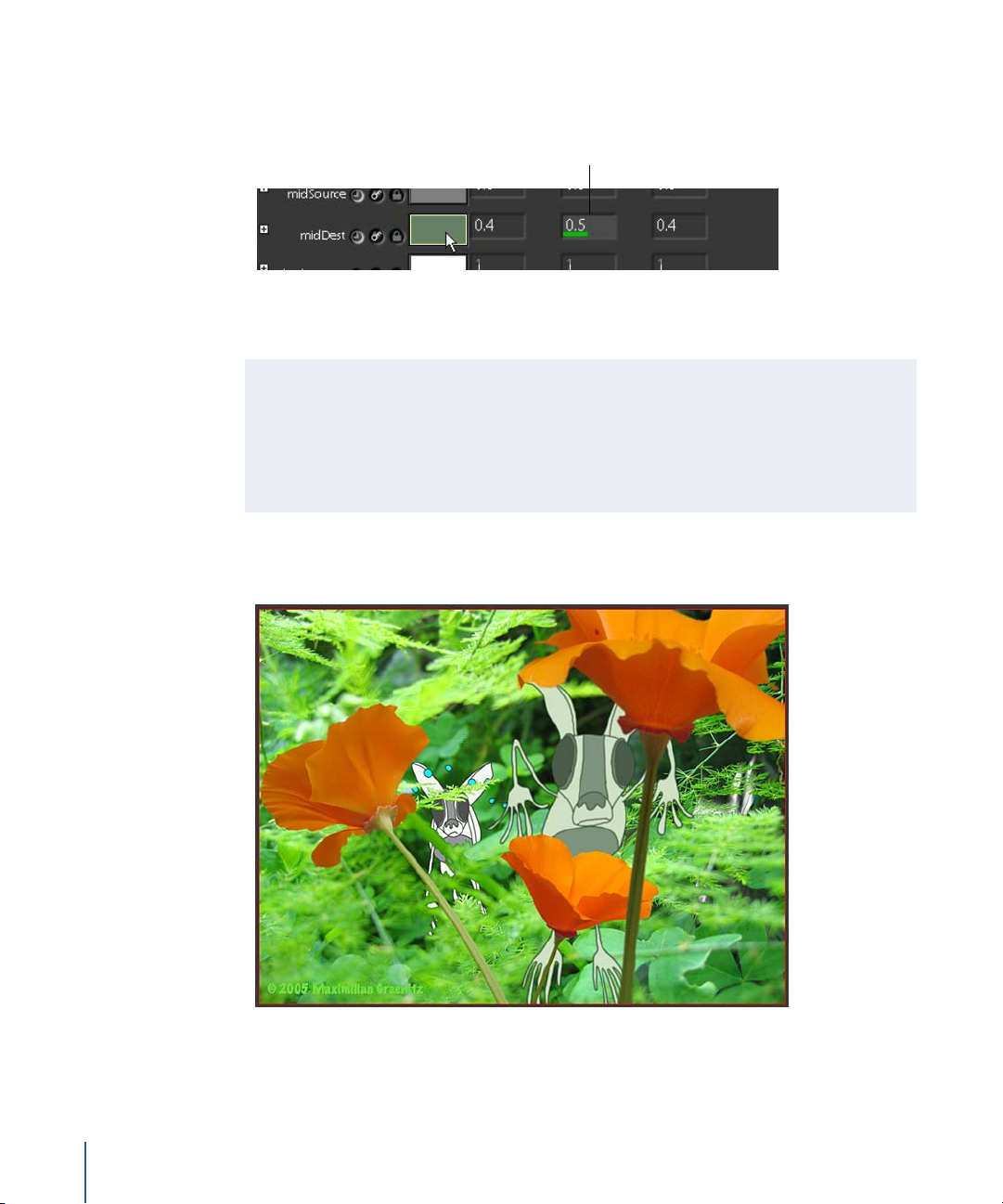
To adjust colors with the keystroke modifiers:
1 Hold down the G key on your keyboard while dragging over the midDest color control,
until the rgb channels are set to 0.4, 0.5, and 0.4.
Green channel value
l
2 Using the keystroke modifiers or the color sliders, continue to make adjustments to the
low, mid, and high destination values until you get a result that you like.
Keystroke Modifiers for Color Controls
Hold down one of the following modifier keys while dragging inside a color control
to adjust the color according to a specific property.
R = Red, G = Green, B = Blue, O= Offset, H=Hue, S=Saturation, V=Value,
T=Temperature, C=Cyan, M=Magenta, Y=Yellow, and L=Luminance.
You should have a fairly good match between the background and wawa1. Now apply
that color correction to the other characters.
You could copy and paste the node to apply it to the other characters. However, if you
decide to make changes , you’ll need to update every instance of the ColorMatch node.
86 Tutorial 2 Intermediate Skills
Page 87

Since you have multiple characters—and they’re composited at different places in the
node tree, a better method is to copy and clone the ColorMatch node. Then, when you
adjust the original color correction, your changes will apply to the base colors of the
other characters, also.
To clone the color correction node:
1 Select the ColorMatch1 node and press Command-C or Control-C to copy it.
2 Press Shift-Command-V or Shift-Control-V to paste a copy of node as a clone of
ColorMatch1.
3 Drag the copy over the noodle that connects the wawa2 node to the Composite node.
There! You have a new node called ColorMatch1_clone. If you need more proof that it’s
a clone—and a visual reminder of the node it’s linked to—turn on the enhanced Node
View.
4 Right-click in the Node View, then choose Enhanced Node View from the shortcut
menu (or press Control-E).
Tutorial 2 Intermediate Skills 87
Page 88

You see a connection between the original ColorMatch node and the clone, with an
arrow pointing toward the parent.
5 Press Shift-Control-V again to paste another ColorMatch1 clone, and drag it to the
noodle under wawa3.
6 Press Control-E to turn off enhanced Node View.
Changes in ColorMatch1 will be applied also to ColorMatch1_clone1, and any other
clones of ColorMatch1—as long as you do not change the parameters of the clones. If,
for example, you manually adjust the ColorMatch1_clone3 parameters, they will not
update with future changes from ColorMatch1.
Note: When you create a clone from a node, Shake links all parameters of the clone to
its parent. When you change individual parameters in the clone, this breaks the link to
the parent for the changed parameters only; any unchanged parameters remain linked
to the parent. The magenta connection line appears in Enhanced Node View as long as
at least one parameter is linked between clone and parent.
Extended View also includes other display changes to give you a better overview of the
current script and the relationships between the nodes. For more information, see
Chapter 7, “Using the Node View” in the Shake 4 User Manual.
88 Tutorial 2 Intermediate Skills
Page 89

Now that you’ve color corrected the base colors of the characters, you can add other
nodes to simulate lighting for their positions at various distances from the camera.
To adjust brightness for wawa3:
1 Select the wawa3 node and insert a Color–Brightness node.
2 In the Brightness1 parameters, set the value slider to 0.88.
The final character, wawa2, is moving into a shadowed area of the background. Use the
Mult color-correction node and animate its settings to darken the character as it moves
out of frame.
To animate the color correction for wawa2:
1 Select the wawa2 node and insert a Color–Mult node (not MMult).
2 Drag the playhead to frame 15.
3 In the Mult1 node parameters, click the AutoKey button next to the Mult color control.
This sets the first keyframe at frame 15.
4 Drag the playhead to frame 30.
5 While holding down the L key, drag over the Mult1 color control, until the RGB values
look similar to this:
Tutorial 2 Intermediate Skills 89
Page 90

It doesn’t need to be exactly the same as the illustration, but the color correction on
wawa2, should match the dark area in the background. The goal is to animate this color
correction so that the wawa appears to be retreating into the shadows.
Before Mult After Mult
You’re finished with the field wawas! Again, good work!
6 Click the Save button to save your changes to the file on disk.
7 Click the Flipbook button to preview the completed composite.
90 Tutorial 2 Intermediate Skills
Page 91

3 Depth Compositing
This tutorial demonstrates different methods for creating
“real” and simulated depth in your composites. You’ll
start with Z channels and filtering options. Then you’ll
work with the MultiPlane node.
3
Tutorial Summary
• Simulated depth and 3D compositing
• Working with Z channels
• Creating composites with ZCompose node
• Color correcting premultiplied images
• Fading with distance
• 3D compositing and the MultiPlane node
• Animating a MultiPlane camera
• Importing camera and animation data
91
Page 92

Simulated Depth and 3D Compositing
In this tutorial, you’ll use various methods to create the illusion of depth in composites.
You can simulate 3D transformations by positioning, scaling, and rotating the images in
the composite. Shake can also perform Z channel operations to filter and mask
elements, according to the perceived distance from the “camera” or viewing plane.
The MultiPlane node provides another method by compositing elements in 3D space
(with x, y, and z axes). Animated camera moves simulate the change in depth and
perspective. You can also import animation data from third-party software, and utilize
the “camera” and point cloud data in the MultiPlane 3D compositing space.
The images for this tutorial were produced by Adonic Film, Los Angeles.
Setting Up the Depth Composite
Start by reading in the images for the first project. You’ll use these images to review
basic information about compositing for simulated depth.
To read in the images for a Z channel composite:
1 In a new Shake script, insert an Image–FileIn node.
2 When the File Browser appears, navigate to $HOME/nreal/Tutorial_Media/Tutorial_03/
images/depth.
Shift-click to select balloons.iff, city_bg.jpg, and city_bg_depth.jpg. Then click OK.
You’ll see the following nodes in the Node View. The balloons.iff image has the Z
channel embedded in the file.
92 Chapter 3 Depth Compositing
Page 93
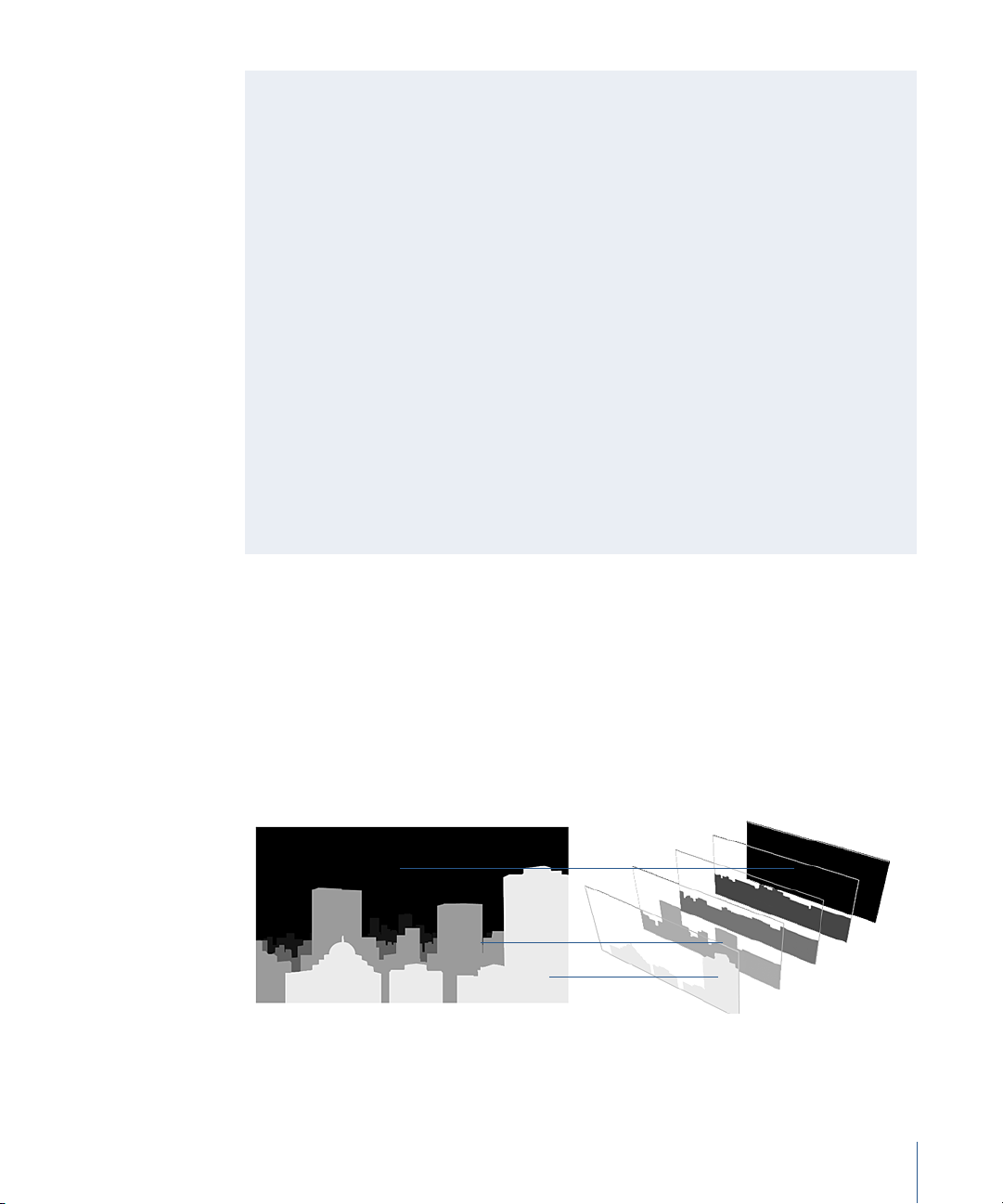
Launching Shake Projects From Terminal
Here’s something you can try to speed up your workflow in Shake: Open a Terminal
window and enter simple commands that perform the compositing functions before
you launch the Shake interface.
The following steps provide an alternative way to read images into Shake:
1 Open Terminal, found in the Applications/Utilities folder.
2 In the Terminal window, type the following:
cd nreal/Tutorial_Media/Tutorial_03/images/depth
The “cd” command tells Terminal to change directories according to the specified
path.
3 At the Terminal prompt, type:
shake balloons.iff city_bg.jpg city_bg_depth.jpg -gui
4 Press Return.
The “shake” command tells Terminal to read in three image files, and the “-gui”
command at the end of the line prompts Terminal to open the Shake graphical user
interface.
Working With Z Channels
Most compositing depends on the information in the R, G, B, and alpha channels to
create a final composite. An optional channel, called the Z channel, stores depth
information as a grayscale image. Unlike the alpha channel or a rotoshape, the Z
channel represents perceived distances from the viewing plane and image masks in
varying degrees, allowing elements to appear in front of and behind other elements in
the composite. Lighter values are interpreted as being closer to the viewing plane.
Progressively darker values indicate increased distance from the viewing plane.
0.000
0.545
0.898
Chapter 3 Depth Compositing 93
Page 94

As shown in the illustration above, Shake orders these pixels and outputs the higher
values when it layers the images for the composite. Z channels are usually rendered
from 3D animation software, where each pixel has a known distance from the camera.
Note: You may need to make adjustments—inverting the grayscale image, for
example—to make the Z channel from your animation software work in a Shake
composite. This is because there are different methods for processing depth
information and your software may not match the method Shake uses to handle Z
channel data.
A Z channel can be rendered into the same file as the RGBA channels. You can also
generate and save a Z channel file—either with 3D animation software or a paint
program—and then use the Shake Reorder and Copy nodes to incorporate the Z
channel into an image. This latter method is useful when working with live-action
plates and other elements that do not have a rendered Z channel.
These images show the Z channels for the images in the first example of this tutorial:
balloons.iff includes five channels: RGBA (left) and Z (right).
city_bg.jpg include three channels: RGB.
The Z channel for balloons.iff was rendered from the original 3D scene file that created
that image, and is stored as one of the channels in the file. The Z channel for the city
background was hand-painted in an image editor. In this tutorial, you’ll incorporate this
separate image as the Z channel for the background.
94 Chapter 3 Depth Compositing
The hand-painted city_bg_depth.jpg will be added
to city_bg.jpg as a Z channel.
Page 95

Displaying Z Channels
The Z channel—or lack of it—in the background image is a problem because some of
the balloons and dirigibles should appear in front of the buildings, while others should
appear behind buildings.
Background image, no Z channel Background image, with Z channel mask
This background is a 3D image. You could render a Z channel for it, when you have the
animation file. If the background were a live-action plate, however, that wouldn’t be an
option—not without recreating the entire scene in 3D.
You could create a bunch of rotoshape masks to handle the overlapping elements, but
just look at all those balloons and buildings. Do you really want to roto them? No.
Fortunately, there’s a much easier solution. You can build your own the Z channel using
a hand-painted mask of the background image, then combine it with the existing Z
channel in the balloon image.
When you load an image containing a Z channel into the Viewer, “RGBAZ” appears in
the Viewer title bar. To display the Z channel in the Viewer, you must activate a Viewer
script.
Additional Viewing and Framing Tips
• With the pointer over the Viewer, press the Home key to reset an image to a 1:1
view ratio. Any visual artifacts caused by a non-integer zoom are removed.
• Press + / – (near the Delete / Backspace key) to zoom the image. The location of the
pointer determines the point of zoom.
• Shift-F ensures that the Viewer title bar is visible. The Viewer title bar displays
information about the image.
For example, “BWAZ” in the Viewer title bar tells you that you are looking at an 8-bit
black-and-white image with alpha and Z channels.
Chapter 3 Depth Compositing 95
Page 96

To view the Z channel of an image:
1 Load the balloons node into the Viewer.
2 Press and hold the Viewer Script button, then choose the View Z button from the pop-
up menu.
The Viewer displays the Z channel embedded in the balloons.iff file.
3 To see the numerical Z values, right-click the View Z button, then choose Load Viewer
Script Controls into Parameters2 Tab from the shortcut menu.
4 In the Parameters2 tab, set the floatZinA parameter to Original or Distance.
The parameters for the View Z script also include display options to normalize Z values
for Maya or 3ds Max files, and to adjust the depth range.
5 In the Viewer shelf, click the View Channel button to toggle to alpha channel view. The
Viewer displays an inverted view of the Z channel for balloons.iff.
96 Chapter 3 Depth Compositing
Page 97

The real Z values are placed into the alpha channel for analysis. The inverted display is a
result of the Alpha channel view.
6 Click a pixel or drag over the image to display the Z distance value at the top of the
Viewer, shown as the “alpha” value.
When the View Z script is active, you can use the Pixel Analyzer to get the minimum
and maximum values in terms of distance.
7 Click the Pixel Analyzer tab (in the row of tabs beneath the Node View).
The Pixel Analyzer opens.
8 Set Mode to Image, to analyze all displayed pixels, then click the Maximum color control.
The maximum distance value is displayed in the Alpha channel field. Click any of the
other Value Range options to change the display range (for example, 0-255, 0-1023, and
so on).
9 Click the Minimum color control to display the minimum distance value in the Alpha
channel field.
Chapter 3 Depth Compositing 97
Page 98
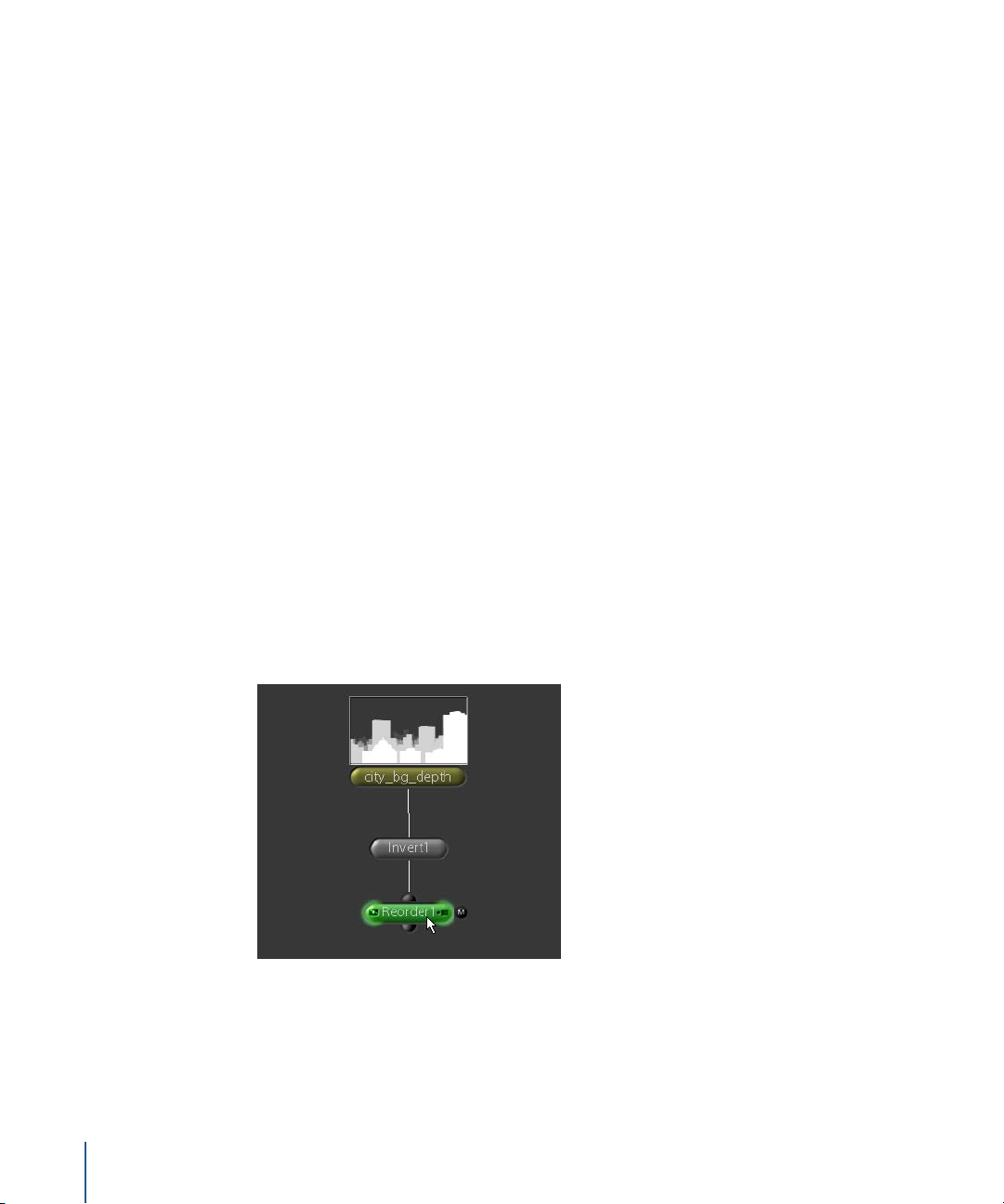
Some software processes Z channel data differently than Shake. If you’re using 3ds Max,
for example, you’ll see negative values in the Z channel of the rendered image. If you’re
using a Maya-rendered image, you’ll see values calculated as –1/distance. Setting the
floatZinA parameter to Distance returns the actual distance from the camera. You can
also choose to “normalize” the Z channel data for either Maya or 3ds Max by selecting
the appropriate item in the zNormalize parameter.
10 Click the View Z button to disable the Viewer script, then press C to reset the Viewer to
display all color channels.
Creating Composites With ZCompose
In the next example, use the ZCompose node to composite these elements together.
The ZCompose node is designed to consider five channels—R, G, B, A, and Z—when
layering images. A little preparation is required to convert the painted Z channel
(city_bg_depth.jpg) into a proper Z channel for the background image.
To prepare the Z channel for the city_bg_depth image:
1 In the Node View, select the city_bg_depth node.
2 Apply a Color–Invert node.
Why the Invert node? The Z data must be inverted for one of the images, because the Z
channels don’t match. In the city_bg_depth image, the pixel values go from light to
dark as distance increases, while in balloons.iff, the inverse is true. Therefore, you need
to invert the city_bg_depth image to match the Z channel of the other image.
3 With the Invert1 node selected, add a Color–Reorder node.
The Reorder node will create a Z channel for this image by copying another channel
(red) to the Z channel position.
98 Chapter 3 Depth Compositing
Page 99

4 In the Reorder parameters, enter “rgbar” in the channels value field. This string specifies
that red goes to the red channel, green to the green channel, blue to the blue channel,
alpha to the alpha channels, and red again to the fifth channel—the Z channel.
You now have a Z channel for the background. Next, you’ll copy this Z channel to the
city_bg image.
To copy the Z channel to the city_bg image:
1 In the Node View, select the city_bg node.
2 Attach a Layer–Copy node.
3 Connect the Reorder1 node to the second input of Copy1.
4 In the Copy1 parameters, enter “z” in the channels field. This copies the Z channel from
the Reorder1 node to the city_bg image.
Now, with the Z channels in place, you can create the composite using a ZCompose
node. ZCompose takes two images and uses the Z channel values to “stack” the RGBA
pixels by comparing which image has the lower Z value. The order in which the layers
are composited does not matter. Instead, the pixels with the higher Z values are
composited on top and passed down the tree.
To composite balloons and city_bg using ZCompose:
1 In the Node View, select the balloons node.
2 Attach a Layer–ZCompose node.
Chapter 3 Depth Compositing 99
Page 100

3 Connect the Copy1 node to the second input of ZCompose1.
So what’s the result? Probably different than you expected. There are several places
where the balloon images are not masked by the Z channel.
ZCompose will not work properly unless all images have an alpha channel. In this case,
you need to create an alpha channel for the city_bg.jpg image.
To create an alpha channel for city_bg:
1 Double-click the city_bg node to load it into the Viewer and into the Parameters tab.
2 Click the View Channel button in the Viewer shelf to display the alpha channel.
The screen goes black, which indicates that the city_bg image does not have an alpha
channel.
100 Chapter 3 Depth Compositing
 Loading...