

Page 1

Shake 4
User Manual
Page 2

Apple Computer, Inc.
© 2005 Apple Computer, Inc. All rights reserved.
Under the copyright laws, this manual may not be
copied, in whole or in part, without the written consent
of Apple. Your rights to the software are governed by
the accompanying software license agreement.
The Apple logo is a trademark of Apple Computer, Inc.,
registered in the U.S. and other countries. Use of the
keyboard Apple logo (
Option-Shift-K
) for commercial
purposes without the prior written consent of Apple
may constitute trademark infringement and unfair
competition in violation of federal and state laws.
Every effort has been made to ensure that the
information in this manual is accurate. Apple Computer,
Inc. is not responsible for printing or clerical errors.
Apple Computer, Inc.
1 Infinite Loop
Cupertino, CA 95014-2084
408-996-1010
www.apple.com
Apple, the Apple logo, Final Cut, Final Cut Pro, FireWire,
Mac, Macintosh, Mac OS, Nothing Real, QuickTime,
Shake, and TrueType are trademarks of Apple Computer,
Inc., registered in the U.S. and other countries. Exposé
and Finder are trademarks of Apple Computer, Inc.
Adobe is a trademark of Adobe Systems Inc.
Cineon is a trademark of Eastman Kodak Company.
Maya, Alias, Alias/Wavefront, and O2 are trademarks of
SGI Inc.
3ds Max is a trademark of Autodesk Inc.
Softimage and Matador are registered trademarks of
Avid Technology, Inc.
Times is a registered trademark of Heidelberger
Druckmaschinen AG, available from Linotype Library
GmbH.
Other company and product names mentioned herein
are trademarks of their respective companies. Mention
of third-party products is for informational purposes
only and constitutes neither an endorsement nor a
recommendation. Apple assumes no responsibility with
regard to the performance or use of these products.
ACKNOWLEDGEMENTS
Portions of this Apple software may utilize the following
copyrighted material, the use of which is hereby
acknowledged.
Double Negative Visual Effects (OpenEXR): Portions of
the OpenEXR file translator plug-in are licensed from
Double Negative Visual Effects.
FilmLight Limited (Truelight): Portions of this software
are licensed from FilmLight Limited. © 2002-2005
FilmLight Limited. All rights reserved.
FLEXlm 9.2 © Globetrotter Software 2004. Globetrotter
and FLEXlm are registered trademarks of Macrovision
Corporation.
Framestore Limited (Keylight): FS-C Keylight v1.4 32 bit
version © Framestore Limited 1986-2002.
Industrial Light & Magic, a division of Lucas Digital Ltd.
LLC (OpenEXR): Copyright © 2002 All rights reserved.
Redistribution and use in source and binary forms, with
or without modification, are permitted provided that
the following conditions are met:
Redistributions of source code must retain the above
copyright notice, this list of conditions and the following
disclaimer.
Redistributions in binary form must reproduce the
above copyright notice, this list of conditions and the
following disclaimer in the documentation and/or other
materials provided with the distribution.
Neither the name of Industrial Light & Magic nor the
names of its contributors may be used to endorse or
promote products derived from this software without
specific prior written permission.
THIS SOFTWARE IS PROVIDED BY THE COPYRIGHT HOLDERS
AND CONTRIBUTORS "AS IS" AND ANY EXPRESS OR IMPLIED
WARRANTIES, INCLUDING, BUT NOT LIMITED TO, THE IMPLIED
WARRANTIES OF MERCHANTABILITY AND FITNESS FOR A
PARTICULAR PURPOSE ARE DISCLAIMED. IN NO EVENT SHALL
THE COPYRIGHT OWNER OR CONTRIBUTORS BE LIABLE FOR ANY
DIRECT, INDIRECT, INCIDENTAL, SPECIAL, EXEMPLARY, OR
CONSEQUENTIAL DAMAGES (INCLUDING, BUT NOT LIMITED TO,
PROCUREMENT OF SUBSTITUTE GOODS OR SERVICES; LOSS OF
USE, DATA, OR PROFITS; OR BUSINESS INTERRUPTION) HOWEVER
CAUSED AND ON ANY THEORY OF LIABILITY, WHETHER IN
CONTRACT, STRICT LIABILITY, OR TORT (INCLUDING NEGLIGENCE
OR OTHERWISE) ARISING IN ANY WAY OUT OF THE USE OF THIS
SOFTWARE, EVEN IF ADVISED OF THE POSSIBILITY OF SUCH
DAMAGE.
Oliver James (Keylight 32-bit support): © 2005 Apple
Computer, Inc. All rights reserved.
This new version has been updated by Oliver James, one
of Keylight's original authors, to provide full support for
floating point images.
Thomas G. Lane ( JPEG library ): © 1991-1998 Thomas G.
Lane. All rights reserved except as specified below.
The authors make NO WARRANTY or representation,
either express or implied, with respect to this software, its
quality, accuracy, merchantability, or fitness for a
particular purpose. This software is provided AS IS, and
you, its user, assume the entire risk as to its quality and
accuracy. Permission is hereby granted to use, copy,
modify, and distribute this software (or portions thereof)
for any purpose, without fee, subject to these conditions:
(1) If any part of the source code for this software is
Page 3

distributed, then this README file must be included, with
this copyright and no-warranty notice unaltered; and any
additions, deletions, or changes to the original files must
be clearly indicated in accompanying documentation.
(2) If only executable code is distributed, then the
accompanying documentation must state that this
software is based in part on the work of the Independent
JPEG Group. (3) Permission for use of this software is
granted only if the user accepts full responsibility for any
undesirable consequences; the authors accept NO
LIABILITY for damages of any kind. These conditions
apply to any software derived from or based on the IJG
code, not just to the unmodified library. If you use our
work, you ought to acknowledge us. Permission is NOT
granted for the use of any IJG author's name or company
name in advertising or publicity relating to this software
or products derived from it. This software may be
referred to only as the Independent JPEG Group's
software. We specifically permit and encourage the use of
this software as the basis of commercial products,
provided that all warranty or liability claims are assumed
by the product vendor.
Sam Leffler and Silicon Graphics, Inc. (TIFF library):
© 1988-1996 Sam Leffler. Copyright © 1991-1996 Silicon
Graphics, Inc.
Permission to use, copy, modify, distribute, and sell this
software and its documentation for any purpose is
hereby granted without fee, provided that (i) the above
copyright notices and this permission notice appear in
all copies of the software and related documentation,
and (ii) the names of Sam Leffler and Silicon Graphics
may not be used in any advertising or publicity relating
to the software without the specific, prior written
permission of Sam Leffler and Silicon Graphics.
©
THE SOFTWARE IS PROVIDED AS-IS AND WITHOUT
WARRANTY OF ANY KIND, EXPRESS, IMPLIED OR OTHERWISE,
INCLUDING WITHOUT LIMITATION, ANY WARRANTY OF
MERCHANTABILITY OR FITNESS FOR A PARTICULAR PURPOSE.
IN NO EVENT SHALL SAM LEFFLER OR SILICON GRAPHICS BE
LIABLE FOR ANY SPECIAL, INCIDENTAL, INDIRECT OR
CONSEQUENTIAL DAMAGES OF ANY KIND, OR ANY DAMAGES
WHATSOEVER RESULTING FROM LOSS OF USE, DATA OR
PROFITS, WHETHER OR NOT ADVISED OF THE POSSIBILITY OF
DAMAGE, AND ON ANY THEORY OF LIABILITY, ARISING OUT OF
OR IN CONNECTION WITH THE USE OR PERFORMANCE OF
THIS SOFTWARE.
Photron USA, Inc. (Primatte Keyer): © 2004 Photron, USA
Glen Randers-Pehrson, et al. ( png ): libpng version 1.0.8
- July 24, 2000. © 1998-2000 Glenn Randers-Pehrson,
© 1996, 1997 Andreas Dilger, © 1995, 1996 Guy Eric
Schalnat, Group 42, Inc.
COPYRIGHT NOTICE, DISCLAIMER, and LICENSE
For the purposes of this copyright and license,
Contributing Authors is defined as the following set of
individuals: Andreas Dilger, Dave Martindale, Guy Eric
Schalnat, Paul Schmidt, Tim Wegner.
The PNG Reference Library is supplied AS IS. The
Contributing Authors and Group 42, Inc. disclaim all
warranties, expressed or implied including, without
limitation, the warranties of merchantability and of
fitness for any purpose. The Contributing Authors and
Group 42, Inc. assume no liability for direct, indirect,
incidental, special, exemplary, or consequential
damages, which may result from the use of the PNG
Reference Library, even if advised of the possibility of
such damage.
Permission is hereby granted to use, copy, modify, and
distribute this source code, or portions hereof, for any
purpose, without fee, subject to the following restrictions:
1. T he origin of this source code must not be
misrepresented. 2. Altered versions must be plainly
marked as such and must not be misrepresented as
being the original source. 3. This Copyright notice may
not be removed or altered from any source or altered
source distribution. The Contributing Authors and Group
42, Inc. specifically permit, without fee, and encourage
the use of this source code as a component to
supporting the PNG file format in commercial products.
If you use this source code in a product, acknowledgment
is not required but would be appreciated.
Julian R. Seward ( bzip2 ): © 1996-2002 Julian R Seward.
All rights reserved. Redistribution and use in source and
binary forms, with or without modification, are permitted
provided that the following conditions are met:
1. Redistributions of source code must retain the above
copyright notice, this list of conditions and the following
disclaimer. 2. The origin of this software must not be
misrepresented; you must not claim that you wrote the
original software. If you use this software in a product, an
acknowledgment in the product documentation would
be appreciated but is not required. 3. Altered source
versions must be plainly marked as such, and must not
be misrepresented as being the original software. 4. The
name of the author may not be used to endorse or
promote products derived from this software without
specific prior written permission.
THIS SOFTWARE IS PROVIDED BY THE AUTHOR ``AS IS'' AND
ANY EXPRESS OR IMPLIED WARRANTIES, INCLUDING, BUT NOT
LIMITED TO, THE IMPLIED WARRANTIES OF MERCHANTABILITY
AND FITNESS FOR A PARTICULAR PURPOSE ARE DISCLAIMED.
IN NO EVENT SHALL THE AUTHOR BE LIABLE FOR ANY DIRECT,
INDIRECT, INCIDENTAL, SPECIAL, EXEMPLARY, OR
CONSEQUENTIAL DAMAGES (INCLUDING, BUT NOT LIMITED TO,
PROCUREMENT OF SUBSTITUTE GOODS OR SERVICES; LOSS OF
USE, DATA, OR PROFITS; OR BUSINESS INTERRUPTION)
HOWEVER CAUSED AND ON ANY THEORY OF LIABILITY,
WHETHER IN CONTRACT, STRICT LIABILITY, OR TORT (INCLUDING
NEGLIGENCE OR OTHERWISE) ARISING IN ANY WAY OUT OF THE
USE OF THIS SOFTWARE, EVEN IF ADVISED OF THE POSSIBILITY
OF SUCH DAMAGE.
Julian Seward, Cambridge, UK.
jseward@acm.org
bzip2/libbzip2 version 1.0.2 of 30 December 2001
Page 4

Page 5

1
Contents
Preface 15 Shake 4 Documentation and Resources
15
What Is Shake?
16
Using the Shake Documentation
16
Onscreen Help
17
Contextual Help
17
Apple Websites
18
Keyboard and Mouse Conventions on Different Platforms
19
Using a Stylus
20
Using Dual-Head Monitors
Chapter 1 23 An Overview of the Shake User Interface
23
Opening Shake
24
Overview of the Shake User Interface
27
Making Adjustments to the Shake Window
28
Navigating in the Viewer, Node View, and Curve Editor
30
Working With Tabs and the Tweaker
31
Menus and the Title Bar
35
Script Management
38
The File Browser
45
Using and Customizing Viewers
72
The Parameters Tabs
78
Using Expressions in Parameters
81
The Parameters Tab Shortcut Menu
82
The Domain of Definition (DOD)
88
The Time Bar
90
Previewing Your Script Using the Flipbook
Chapter 2 91 Setting a Script’s Global Parameters
91
About Global Parameters
92
The Main Global Parameters
98
guiControls
101
Monitor Controls
10 2
Colors
5
Page 6

10 2
enhancedNodeView
10 4
Application Environmental Variables
10 4
Script Environmental Variables
Chapter 3 10 7Adding Media, Retiming, and Remastering
10 7
About Image Input
11 0
Using the FileIn (SFileIn) Node
117
Retiming
12 3
The TimeX Node
12 5
Manual Manipulation of Time
12 6
Remastering Media
13 0
Working With Extremely High-Resolution Images
13 2
Using Shake With Final Cut Pro
Chapter 4 13 7Using Proxies
13 7
Using Proxies
13 9
Using interactiveScale
141
Using Temporary Proxies
14 4
Permanently Customizing Shake’s Proxy Settings
14 8
Using Pre-Generated Proxy Files Created Outside of Shake
15 0
Pre-Generating Your Own Proxies
163
When Not to Use Proxies
164
Proxy Parameters
Chapter 5 167Compatible File Formats and Image Resolutions
167
File Formats
17 0
Table of Supported File Formats
17 3
Format Descriptions
17 8
Support for Custom File Header Metadata
18 0
Table of File Sizes
18 0
Controlling Image Resolution
183
Nodes That Affect Image Resolution
18 6
Cropping Functions
Chapter 6 191 Importing Video and Anamorphic Film
191
The Basics of Processing Interlaced Video
19 6
Setting Up Your Script to Use Interlaced Images
200
Displaying Individual Fields in the Viewer
204
Integrating Interlaced and Non-Interlaced Footage
205
Video Functions
209
About Aspect Ratios and Nonsquare Pixels
6
Contents
Page 7

Chapter 7 217Using the Node View
217
About Node-Based Compositing
218
Where Do Nodes Come From?
219
Navigating in the Node View
221
Using the Enhanced Node View
224
Noodle Display Options
226
Creating Nodes
228
Selecting and Deselecting Nodes
231
Connecting Nodes Together
235
Breaking Node Connections
235
Inserting, Replacing, and Deleting Nodes
240
Moving Nodes
240
Loading a Node Into a Viewer
241
Loading Node Parameters
243
Ignoring Nodes
243
Renaming Nodes
244
Arranging Nodes
246
Groups and Clusters
251
Opening Macros
251
Cloning Nodes
253
Thumbnails
257
The Node View Shortcut Menu
Chapter 8 261Using the Time View
261
About the Time View
262
Viewing Nodes in the Time View
263
Clip Durations in the Time View
263
Adjusting Image Nodes in the Time View
270
The Transition Node
Chapter 9 277Using the Audio Panel
277
About Audio in Shake
278
Loading, Refreshing, and Removing Audio Files
280
Previewing and Looping Audio
282
Playing Audio With Your Footage
283
Viewing Audio
283
Slipping Audio Sync in Your Script
285
Extracting Curves From Sound Files
288
Exporting an Audio Mix
Contents
7
Page 8

Chapter 10 291 Parameter Animation and the Curve Editor
291
Animating Parameters With Keyframes
294
Using the Curve Editor
298
Navigating the Curve Editor
300
Working With Keyframes
316
More About Splines
Chapter 11 323The Flipbook, Monitor Previews, and Color Calibration
323
Cached Playback From the Viewer
323
Launching the Flipbook
324
Flipbook Controls
325
Viewing, Zooming, and Panning Controls
325
Memory Requirements
326 Creating a Disk-Based Flipbook
330 Viewing on an External Monitor
331 Monitor Calibration With Truelight
Chapter 12 333 Rendering With the FileOut Node
333 Attaching FileOut Nodes Prior to Rendering
336 Rendering From the Command Line
337 Using the Render Parameters Window
339 The Render Menu
339 Support for Apple Qmaster
Chapter 13 343 Image Caching
343 About Caching in Shake
343 Cache Parameters in the Globals Tab
344 Using the Cache Node
349 Commands to Clear the Cache
349 Memory and the Cache in Detail
352 Customizing Image Caching Behavior
Chapter 14 355Customizing Shake
355 Setting Preferences and Customizing Shake
355 Creating and Saving .h Preference Files
359 Customizing Interface Controls in Shake
371 Customizing File Path and Browser Controls
375 Tool Tabs
378 Customizing the Node View
379 Using Parameters Controls Within Macros
386 Viewer Controls
392 Template Preference Files
392 Changing the Default QuickTime Configuration
8
Contents
Page 9

393 Environment Variables for Shake
400 Interface Devices and Styles
401 Customizing the Flipbook
401 Configuring Additional Support for Apple Qmaster
Chapter 15 405 Image Processing Basics
405 About This Chapter
405 Ta king Advantage of the Infinite Workspace
408 Bit Depth
414 Channels Explained
417 Compositing Basics and the Alpha Channel
421 About Premultiplication and Compositing
437 The Logarithmic Cineon File
Chapter 16 451 Compositing With Layer Nodes
451 Layering Node Essentials
452 Compositing Math Overview
453 The Layer Nodes
470 Other Compositing Functions
Chapter 17 473 Layered Photoshop Files and the MultiLayer Node
473 About the MultiLayer Node
473 Importing Photoshop Files
477 Importing a Photoshop File Using the FileIn Node
478 Using the MultiLayer Node
Chapter 18 485 Compositing With the MultiPlane Node
485 An Overview of the MultiPlane Node
487 Using the Multi-Pane Viewer Display
493 Connecting Inputs to a MultiPlane Node
494 Using Camera and Tracking Data From .ma Files
500 Transforming Individual Layers
506 Attaching Layers to the Camera and to Locator Points
512 Parameters in the Images Tab
517 Manipulating the Camera
Chapter 19 527Using Masks
527 About Masks
528 Using Side Input Masks to Limit Effects
530 Using Masks to Limit Color Nodes
533 Masking Concatenating Nodes
534 Masking Transform Nodes
536 Masking Layers
Contents 9
Page 10

539 Masking Filters
540 The -mask/Mask Node
542 Masking Using the Constraint Node
Chapter 20 545 Rotoscoping
545 Options to Customize Shape Drawing
546 Using the RotoShape Node
548 Drawing New Shapes With the RotoShape Node
550 Editing Shapes
556 Copying and Pasting Shapes Between Nodes
557 Animating Shapes
562 Attaching Trackers to Shapes and Points
564 Adjusting Shape Feathering Using the Point Modes
566 Linking Shapes Together
567 Importing and Exporting Shape Data
567 Right-Click Menu on Transform Control
568 Right-Click Menu on Point
568 Viewer Shelf Controls
572 Using the QuickShape Node
Chapter 21 579 Paint
579 About the QuickPaint Node
580 Toggling Between Paint and Edit Mode
580 Paint Tools and Brush Controls
583 Modifying Paint Strokes
585 Animating Strokes
587 Modifying Paint Stroke Parameters
591 QuickPaint Hot Keys
591 QuickPaint Parameters
594 StrokeData Synopsis
Chapter 22 597 Shake-Generated Images
597 Generating Images With Shake
597 Checker
598 Color
599 ColorWheel
600 Grad
601 Ramp
602 Rand
603 RGrad
604 Te xt
609 Tile
10 Contents
Page 11

Chapter 23 611Color Correction
611 Bit Depth, Color Space, and Color Correction
612 Concatenation of Color-Correction Nodes
615 Premultiplied Elements and CG Element Correction
617 Color Correction and the Infinite Workspace
620 Using the Color Picker
625 Using a Color Control Within the Parameters Tab
627 Customizing the Palette and Color Picker Interface
627 Using the Pixel Analyzer
631 The PixelAnalyzer Node
635 Color-Correction Nodes
637 Atomic-Level Functions
646 Utility Correctors
659 Consolidated Color Correctors
674 Other Nodes for Image Analysis
Chapter 24 681 Keying
681 About Keying and Spill Suppression
682 Pulling a Bluescreen or Greenscreen
683 Combining Keyers
687 Blue and Green Spill Suppression
691 Edge Treatment
696 Keying DV Video
702 Keying Functions
Chapter 25 717 Image Tracking, Stabilization, and SmoothCam
717 About Image Tracking Nodes
720 Image Tracking Workflow
728 Strategies for Better Tracking
733 Modifying the Results of a Track
739 Saving Tracks
740 Tracking Nodes
754 The SmoothCam Node
Chapter 26 763Transformations, Motion Blur, and AutoAlign
763 About Transformations
764 Concatenation of Transformations
766 Inverting Transformations
766 Onscreen Controls
775 Scaling Images and Changing Resolution
778 Creating Motion Blur in Shake
783 The AutoAlign Node
794 The Transform Nodes
Contents 11
Page 12

Chapter 27 807 Warping and Morphing Images
807 About Warps
807 The Basic Warp Nodes
821 The Warper and Morpher Nodes
830 Creating and Modifying Shapes
845 Using the Warper Node
854 Using the Morpher Node
Chapter 28 861 Filters
861 About Filters
861 Masking Filters
864 The Filter Nodes
Chapter 29 895 Optimizing and Troubleshooting Your Scripts
895 Optimization
899 Problems With Premultiplication
900 Unwanted Gamma Shifts During FileIn and FileOut
902 Avoiding Bad Habits
Chapter 30 905 Installing and Creating Macros
905 How to Install Macros
907 Creating Macros—The Basics
914 Creating Macros—In Depth
Chapter 31 935 Expressions and Scripting
935 What’s in This Chapter
935 Linking Parameters
937 Variables
939 Expressions
941 Reference Tables for Functions, Variables, and Expressions
947 Using Signal Generators Within Expressions
951 Script Manual
Chapter 32 963 The Cookbook
963 Cookbook Summary
963 Coloring Tips
967 Filtering Tips
968 Keying Tips
974 Layering Tips
977 Transform Tips
979 Creating Depth With Fog
980 Te xt Treatments
984 Installing and Using Cookbook Macros
985 Command-Line Macros
12 Contents
Page 13

986 Image Macros
989 Color Macros
993 Relief Macro
993 Key Macros
994 Transform Macros
996 Warping With the SpeedBump Macro
996 Utility Macros
10 01 Using Environment Variables for Projects
Appendix A 1005 Keyboard Shortcuts and Hot Keys
1005 Keyboard Shortcuts in Shake
Appendix B 1015 T he Shake Command-Line Manual
1015 Viewing, Converting, and Writing Images
Index 10 31
Contents 13
Page 14

14 Contents
Page 15

Shake 4 Documentation and Resources
Welcome to the world of Shake 4 compositing. This
chapter covers where to find help, how the keyboard and
mouse work on different platforms, and how to set up
Shake for use with a stylus.
What Is Shake?
Shake is a high-quality, node-based compositing and visual effects application for film
and video. Shake supports most industry-standard graphics formats, and easily
accommodates high-resolution and high bit depth image sequences and QuickTime
files (Mac OS X only).
Among Shake’s many built-in tools are industry-standard keyers for pulling bluescreens
and greenscreens, a complete suite of color-correction tools, features for high-quality
motion retiming and format remastering, motion tracking, smoothing, and stabilization
capabilities, integrated procedural paint tools, and a rotoscoping and masking
environment that provides complete control over animated and still mattes. Shake also
supports an extensive list of third-party plug-ins, and is compatible across both the
Mac OS X and Linux platforms.
Preface
Shake is also an image-processing tool that can be used as a utility for media being
passed along a pipeline of many different graphics applications. Large facilities can use
Shake to process and combine image data from several different departments—for
example, taking a project from initial film recording; providing processed images and
tools for use by the 3D animation, digital matte, and roto departments; recombining
the output from all these groups with the original plates for compositing; and
ultimately sending the final result back out for film recording.
Shake’s tools can be accessed in several different ways. While most artists work within
the graphical interface, advanced users can access a command-line tool running from
the Terminal. Likewise, more technically oriented users can perform complex image
processing by creating scripts (the Shake scripting language is similar to C), thereby
using Shake as an extensive image-manipulation library.
15
Page 16

Using the Shake Documentation
There are several components to the documentation accompanying Shake, including
printed user manuals and tutorials, onscreen documentation in PDF and HTML formats,
and contextual help available directly from within the Shake interface.
User Manual
The Shake 4 User Manual is divided into two volumes:
• Volume I—The Interface: Explains the basics of the Shake interface and provides
instructions for working with media, file formats, nodes, and so on.
• Volume II—Compositing: Discusses the specific features Shake provides for image
compositing. Part I of this volume covers such topics as image processing,
rotoscoping, color correction, and so on. Part II delves into Shake’s advanced
functionality, including optimizing, creating macros, and using expressions. This
section also includes “The Cookbook,” a repository of useful Shake tips and
techniques.
Tutorials
If you are new to Shake, you are encouraged to work through the Shake 4 Tutorials.
These interactive lessons provide you with a solid introduction to Shake’s functionality
and workflow.
Onscreen Help
Onscreen help (available to Mac OS X users in the Help menu) provides easy access to
information while you’re working in Shake. Onscreen versions of the Shake 4 User
Manual and Shake 4 Tutorials are available here, along with other documents in PDF
format and links to websites.
To access onscreen help in Mac OS X:
m
In Shake, choose an option from the Help menu.
Note: You can also open PDF versions of the user manual and tutorials from the
Shake/doc folder.
Viewing Shake Onscreen Documentation on Linux Systems
To view Shake onscreen documentation on a Linux system, you’ll need to download
and install Adobe Acrobat Reader, then configure the PDF browser path in the Shake
application.
To configure the PDF browser path in Shake:
1 Open the Globals tab.
2 Open the guiControl subtree (click the “+” sign).
The subtree expands.
16 Preface Shake 4 Documentation and Resources
Page 17
3 Click the folder icon next to the pdfBrowser Path parameter.
The Choose Application window appears.
4 In the Choose Application window, browse to and select the Adobe Acrobat Reader
application.
To save your PDF browser settings in Shake:
1 Choose File > Save Interface Settings.
The “Save preferences to” window appears.
2 In the “Save preferences to” window, save your settings to a defaultui.h file.
Contextual Help
In addition to the onscreen help, the Shake interface provides immediate contextual
help from within the application. Moving the pointer over most controls in Shake
displays their function in the Info field, located at the bottom-right side of the Shake
interface. The Info field provides immediate information about each control’s function.
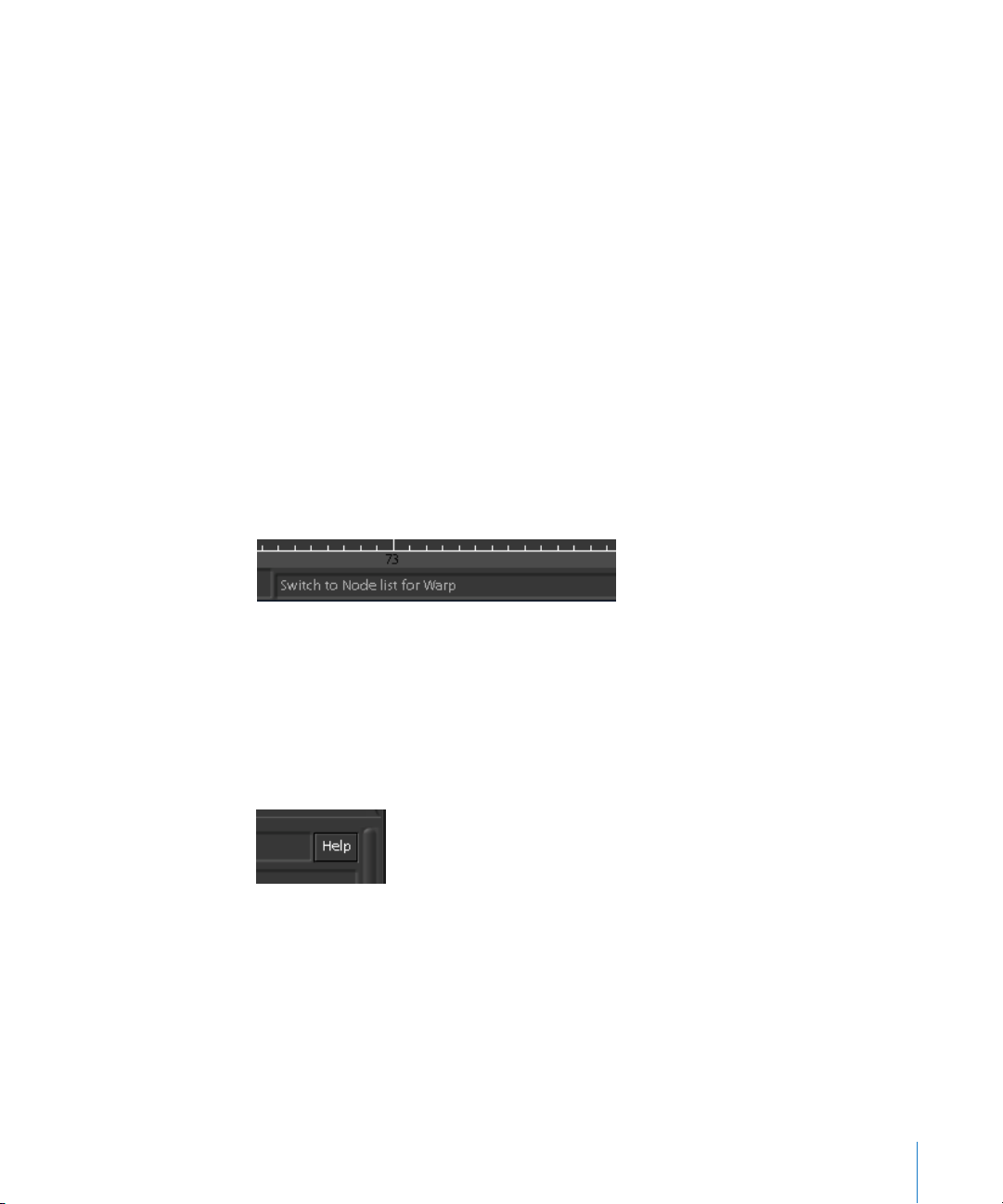
For example, moving the pointer over the Warp tool tab displays the following
information in the Info field.
In addition to the information available from the Info field, each node in Shake has a
corresponding HTML-based contextual help page, available via a special control in the
Parameters tab.
To display a node’s contextual help page:
m
Load a node’s parameters into the Parameters tab, then click the Help button to the
right of the node name field.
Note: Contextual help pages are opened using your system’s currently configured
default web browser.
Apple Websites
There are a variety of discussion boards, forums, and educational resources related to
Shake on the web.
Preface Shake 4 Documentation and Resources 17
Page 18

Shake Websites
The following websites provide general information, updates, and support information
about Shake, as well as the latest news, resources, and training materials.
For more information about Shake, go to:
• http://www.apple.com/shake
To get more information on third-party resources, such as third-party tools and user
groups, go to:
• http://www.apple.com/software/pro/resources/shakeresources.html
An useful listserver, archive, and extensive macro collection are accessible at the
unofficial Shake user community site, HighEnd2D.com:
ttp://www.highend2d.com/shake
h
For more information on the Apple Pro Training Program, go to:
• http://www.apple.com/software/pro/training
Keyboard and Mouse Conventions on Different Platforms
Shake can be used on the Mac OS X and Linux platforms. Functions or commands that
are platform-specific have been documented whenever possible. This section
summarizes the main differences.
• Keyboard: Hot keys or keyboard commands that vary between the Macintosh and
Linux platforms are documented when possible. In most cases, the Command and
Control keys are interchangeable. The Macintosh Delete key located below the F12
key is the equivalent of the Linux Backspace key; the Macintosh Delete key grouped
with the Help, Home, and End keys is the equivalent of the Linux Delete key.
Important: Macintosh users should remember that the Delete key used in Shake is
not the key located below the F12 key but, rather, the one grouped with the Help,
Home, and End keys.
• Mouse: Shake requires the use of a three-button mouse. A three-button mouse
provides quick access to shortcut menus and navigational shortcuts. Shake also
supports the middle scroll wheel of a three-button mouse.
Shake documentation refers to the three mouse buttons as follows:
Mouse Button Documentation Reference
Left mouse button Click
Middle mouse button Middle mouse button or middle-click
Right mouse button Right-click
18 Preface Shake 4 Documentation and Resources
Page 19

Note: This manual uses the term “right-click” to describe how to access shortcut menu
commands.
The following table lists the user manual notation system.
Notation Example
Hot keys/keyboard commands To break a tangent handle in the Curve Editor, Control-click the
handle.
Some hot keys/keyboard
commands vary depending on
the platform. The Mac OS X
command appears first, followed
by the Linux command. The two
hot keys/commands are
separated by a forward slash.
In general, the Command and
Control keys are
interchangeable.
Menu selections are indicated
by angle brackets.
File paths and file names appear
in italics. Also, directories and
file paths are divided by forward
slashes.
Node groups (Tool tabs) appear
in the default font, followed by
the name of the node in italics.
A dash appears between the tab
and node names.
Command-line functions appear
in italics.
Modifications to preferences
files appear in italics.
In the Node View, you can press Control-Option-click / Control-Altclick to zoom in and out.
To open a script, choose File > Open Script.
Temp files are saved in the ..//var/tmp/ directory.
In the Node View, select the Cloud node, and insert a Transform–
CornerPin node.
shake -exec my_script -t 1-240
Add the following lines to a .h file in your startup directory:
script.cineonTopDown = 1;
script.tiffTopDown = 1;
Using a Stylus
Shake is designed to be used with a graphics tablet and stylus.
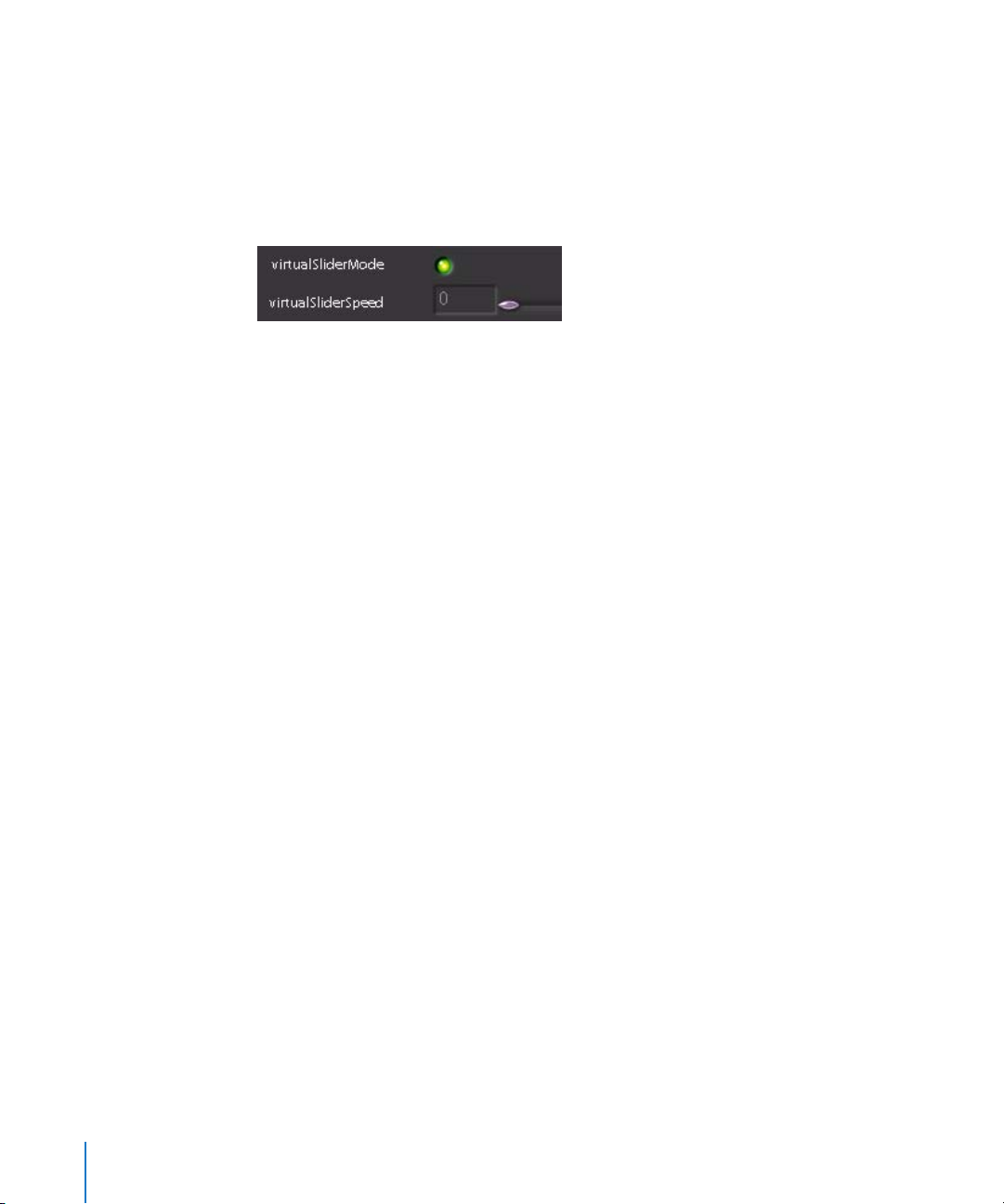
To optimize the Shake interface for use with a tablet and stylus:
1 In the guiControls subtree of the Globals tab, enable virtualSliderMode.
2 Set the parameter virtualSliderSpeed to 0.
Preface Shake 4 Documentation and Resources 19
Page 20
When virtualSliderMode is enabled, the left button always uses the virtual sliders when
when you click a value field. Normally, you have to press Control and drag. However,
when virtualSliderMode is on, dragging left or right in a value field adjusts the value
beyond normal slider limits.
Note: The stylus does not allow you to use your desk space the same way as with a
mouse; consequently, you have to enable virtualSliderMode.
Window Navigation Using a Stylus
Shake makes extensive use of the middle-mouse button to facilitate navigation within
each tab of the interface. To navigate and zoom within Shake easily using a stylus, you
should map the middle mouse button to one of the stylus buttons. Once mapped, you
can use that button to pan around within any section of the Shake interface, or
Control-click and drag with that button to zoom into and out of a section of the
interface.
Using Dual-Head Monitors
You can choose View > Spawn Viewer Desktop to create a new Viewer window that
floats above the normal Shake interface. You can then move this Viewer to a second
monitor, clearing up space on the first for node editing operations.
Important: This technique only works when both monitors are driven by the same
graphics card.
20 Preface Shake 4 Documentation and Resources
Page 21

Part I: Interface, Setup, and Input
Part I presents information about the Shake graphical
user interface as a whole, with detailed information
about all the major interface components.
Chapter 1 An Overview of the Shake User Interface
Chapter 2 Setting a Script’s Global Parameters
Chapter 3 Adding Media, Retiming, and Remastering
Chapter 4 Using Proxies
I
Chapter 5 Compatible File Formats and Image Resolutions
Chapter 6 Importing Video and Anamorphic Film
Chapter 7 Using the Node View
Chapter 8 Using the Time View
Chapter 9 Using the Audio Panel
Chapter 10 Parameter Animation and the Curve Editor
Chapter 11 The Flipbook, Monitor Previews, and Color Calibration
Chapter 12 Rendering With the FileOut Node
Chapter 13 Image Caching
Chapter 14 Customizing Shake
Page 22

Page 23

1 An Overview of the Shake User
Interface
1
This chapter provides a fast introduction to all aspects of
the Shake graphical user interface. It also provides indepth information about navigating the interface, and
customizing it to suit your needs.
Opening Shake
When you open the Shake interface, a blank Shake script appears. Shake scripts
(otherwise known as project files) are unique in that they’re actually a text document
containing the command-line script representation of the node tree that you assemble
in the interface. You can open Shake scripts in any text editor to examine their
contents, and if you’re a power user, you can make modifications to your composite
right within the text of the script itself (this is only recommended if you’re conversant
with Shake’s scripting language, covered in more detail in Part III of this book).
Most of the time, however, you’ll likely stay within Shake’s graphical interface, which
provides specialized controls for performing a wide variety of compositing tasks (many
of which would be far too unwieldy to manipulate from the command line).
Opening Two Scripts at Once
Shake is designed to have only one script open at a time. Typically, each script is used to
create a single compositing project, with a single frame range and a single node tree.
Although Shake supports multiple independent node trees within the same script, all
trees share the same duration, defined by the timeRange parameter in the Globals tab.
If necessary, it is possible to open two scripts simultaneously into interface windows. In
this case, what you’re really doing is launching two instances of Shake at once. This is
primarily useful if you need to copy information from one script to another.
Important: When youopen Shake twice, the first instance of Shake is the only one
that’s able to write to and read from the cache. (For more information on caching in
Shake, see Chapter 13, “Image C
23
aching,” on page 343.)
Page 24
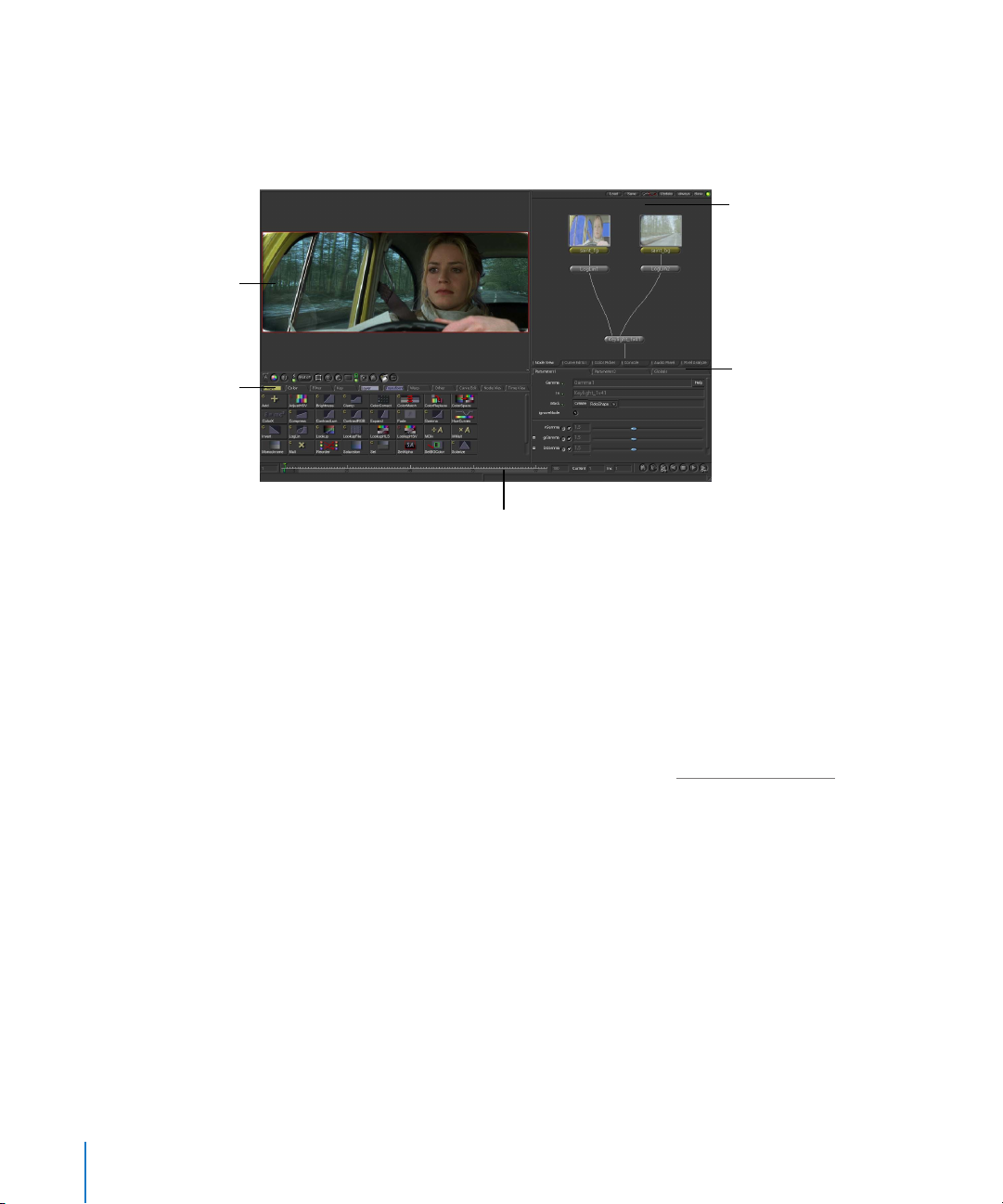
Viewer area
Displays the image at the
selected node in the
node tree.
Tool tabs
All of the available nodes
in Shake are organized
into eight tabs. Click a
node’s icon to add that
node to the node tree.
Overview of the Shake User Interface
The Shake user interface is divided into five main areas: the Viewer, the Tool tabs, the
Parameters/Globals tabs, the Node View/Curve Editor/Color Picker/Audio Panel/Pixel
Analyzer tabs, and the Time Bar at the bottom.
Node View
One of many tabs that
can be displayed here.
The Node View displays
the node tree, which
defines the flow and
processing of image data
in your project.
Parameters tabs
The parameters of
selected nodes appear in
the Parameters1 and 2
tabs. The global
parameters of your
project appear in the
Time Bar area
Lets you navigate among the frames of
your project using the playback
buttons and the playhead.
Images from The Saint provided courtesy of
Framestore CFC and Paramount British Pictures Ltd.
Globals tab.
Node View
The Node View is the heart of Shake, and displays the tree of connected nodes that
modify the flow of image data from the top of the tree down to the bottom. Every
function in Shake is represented as a separate node that can be inserted into the node
tree. You use the Node View to modify, select, view, navigate, and organize your
composite.
For more information on the Node View, see Chapter 7, “U
sing the Node View,” on
page 217.
Viewer Area
The Viewer area is capable of containing one or more Viewers, which display the image
of the currently selected node. You have explicit control over which part of the node
tree is displayed in the Viewer—in fact, the ability to separate the node that’s displayed
in the Viewer from the node being edited in the Parameters tabs is central to working
with Shake. Each Viewer allows you to isolate specific channels from each image. For
example, you can choose to view only the red channel of an image while you make a
color correction, or only the alpha channel when you’re adjusting a key.
24 Chapter 1 An Overview of the Shake User Interface
Page 25

Tool Tabs
The Tool tabs contain groups of nodes, organized by function. Nodes you click in these
tabs are added to the node tree. For example, to add a Keylight node, click the Key tool
tab, and click the Keylight node. The Keylight node then appears in the node tree. If you
right-click a node in any of the Tool tabs, you can choose to insert that node into the
node tree in a variety of different ways, using the shortcut menu.
The Tool tabs area can also display the Curve Editor, Node View, or Time View.
The Time Bar Area
The Time Bar area, at the bottom of the Shake window, displays the currently defined
range of frames. Three fields to the right of the Time Bar show the displayed number of
frames in the Time Bar (not the time range), the current position of the playhead, and
the Increments (Inc) in which the playhead moves. To the right of these fields, the
Viewer playback controls let you step through your composite in different ways.
Command and Help Lines
Underneath the Time Bar area are two additional fields. The Command Line field lets
you enter Shake script commands directly, effectively bypassing the graphical interface.
The Info field provides immediate information about interface controls that you roll the
pointer over.
Parameters Tabs
The two Parameters tabs can be set to display the parameters within a selected node.
You can load two different sets of parameters into each of the two Parameters tabs. The
Globals tab to the right contains the parameters that affect the behavior of the entire
script (such as proxy use, motionBlur, and various interface controls).
Curve Editor
The Curve Editor is a graph on which you view, create, and modify the animation and
Lookup curves that are associated with parameters in the nodes of your script. In
addition to adding and editing the control points defining a curve’s shape, you can
change a curve’s type, as well as its cycling mode.
For more information on using the Curve Editor, see Chapter 10, “P
arameter Animation
and the Curve Editor.”
Color Picker
The Color Picker is a centralized interface that lets you assign colors to node color
parameters by clicking the ColorWheel and luminance bar, clicking swatches from a
color palette, or by defining colors numerically using a variety of color models. You can
also store your own frequently-used color swatches for future use in the Palette.
For more information on how to use the Color Picker, see “U
sing the Color Picker” on
page 620.
Chapter 1 An Overview of the Shake User Interface 25
Page 26

Audio Panel
The Audio Panel lets you load AIFF and WAV audio files for use by your project. Several
different files can be mixed down to create a single file. The audio waveforms can be
displayed inside the Curve Editor. Sound playback can be activated in the Time Bar
playback controls (Mac OS X only).
Note: Because audio playback is handled through the use of Macintosh-specific
QuickTime libraries, you can only hear audio playback on Mac OS X systems. You can
still analyze and visualize audio in Linux.
For more information on the Audio Panel, see Chapter 9, “U
sing the Audio Panel,” on
page 277.
Pixel Analyzer
The Pixel Analyzer is a tool to find and compare different color values on an image. You
can examine minimum, average, current, or maximum pixel values on a selection (that
you make), or across an entire image.
For more information on how to use the Pixel Analyzer, see “U
sing the Pixel Analyzer”
on page 627.
Console
The Console tab displays the data that Shake sends to the OS while in operation. It’s a
display-only tab. Two controls at the top of the Console tab let you change the color of
the text, and erase the current contents of the console. The maximum width of
displayed text can be set via the consoleLineLength parameter, in the guiControls
subtree of the Globals tab.
Getting Help in Shake
There are three ways you can get more information about the Shake interface:
• As you pass the pointer (no need to click) over a node or Viewer, information for
the node appears either in the title bar of the Viewer, or in the bottom-right Info
field. The displayed information includes node name, type, resolution, bit depth,
and channels.
• You can also right-click most buttons to display a pop-up menu listing that button’s
options. You can use this to select a function or to find out what a button does.
• The Help menu contains detailed information on how to use Shake, including the
full contents of this user manual, specifics on new features introduced with the
current release, and late-breaking news about last-minute changes and additions
made to Shake.
26 Chapter 1 An Overview of the Shake User Interface
Page 27
Making Adjustments to the Shake Window
As you work with Shake, there are several methods for resizing and customizing the
various areas of the Shake interface.
To resize any area of the interface:
m
Position the pointer at any border between interface areas and drag to increase or
decrease the size of that area. If you drag an intersection, you can resize multiple areas
at once.
To expand any one area to take up the full screen:
m
Position the pointer in the area you want to expand, and press the Space bar.
m
Press the Space bar again to shrink the area back to its original size.
Note: Use of the Space bar is especially helpful in the Curve Editor, when you are
working with high-resolution elements or large scripts.
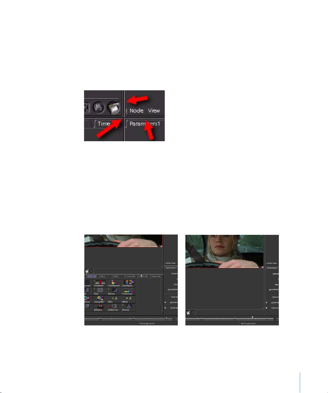
To temporarily hide an area, do one of the following:
m
Drag the top border of the Tool tab or Parameters tab areas down to the bottom.
m
Drag the bottom border of the Viewer, Node View, or any other area up to the top.
Before collapsing Tool tabs After collapsing Tool tabs
That area remains hidden until you drag its top or bottom border back out again.
Chapter 1 An Overview of the Shake User Interface 27
Page 28

Navigating in the Viewer, Node View, and Curve Editor
The Viewer, Node View, and Curve Editor are all capable of containing much more
information than can be displayed at one time. You can pan and zoom around within
each of these areas in order to focus on the elements you want to adjust in greater
detail.
Important: Shake requires the use of a three-button mouse—the middle mouse
button is key to navigating the Shake interface. If, in Mac OS X, you map Exposé
functionality to the middle mouse button, this will interfere with navigation in Shake,
and you should disable this functionality.
To pan across the contents of an area, do one of the following:
m
Press the middle mouse button and drag.
m
Option-click (Mac OS X) or Alt-click (Linux) and drag.
To zoom into or out of an area, do one of the following:
m
Hold down the Control key and drag while holding down the middle mouse button.
m
Control-Option-drag or Control-Alt-drag.
m
Use the + or - key to zoom in or out based on the position of the pointer.
To reset an area to 1:1 viewing, do one of the following:
m
In the Viewer, click the Home button in the Viewer shelf.
m
Move the pointer to an interface area, then press Home.
To fit the contents to the available space within an area:
m
In the Viewer, click the Fit Image to Viewer button in the Viewer shelf.
m
Move the pointer to an interface area, and press F.
Saving Favorite Views
If you find yourself panning back and forth within a particular area to the same regions,
it might be time to create a Favorite View within that area.
• In the Node View, you could save several views in your node tree where you’ll be
making frequent adjustments.
• If you’re doing paint work on a zoomed-in image in the Viewer, you can save the
position and zoom level of several different regions of the image.
• In the Curve Editor, you can save several different pan, zoom-level, and displayed-
curve collections that you need to switch among as you adjust the animation of
different nodes in your project.
• In the Parameters tab, you can save the parameters being tweaked, as well as the
node being displayed in the Viewer.
Once you’ve saved one or more Favorite Views in each interface area, you can instantly
recall the position, zoom level, and state of that area by recalling the Favorite View that
you saved. You can save up to five Favorite Views.
28 Chapter 1 An Overview of the Shake User Interface
Page 29

To define a Favorite View:
1 Pan to a position in an area that contains the region you want to save as a Favorite
View. If necessary, adjust the zoom level to encompass the area that you want to
include.
2 Depending on the area you’re adjusting, you can save additional state information
particular to that area. Make additional adjustments as necessary so that you can recall
the desired project elements:
• In the Node View, you can save the state of the nodes that are currently loaded into
the Viewer and Parameters tabs.
• In the Viewer, you can save the node that’s currently being viewed.
• In the Curve Editor, you can save the curves that are currently loaded and displayed.
• In the Parameters tab, you can save the parameters that are being tweaked, as well
as the node displayed in the Viewer.
3 To save a Favorite View, move the pointer into that area and do one of the following:
• Right-click anywhere within the area, then choose Favorite Views > View N > Save
from the shortcut menu (where N is one of the five Favorite Views you can save).
• Press Shift-F1-5, where F1, F2, F3, F4, and F5 correspond to each of the Favorite
Views.
Restoring Favorite Views
Once you’ve defined one or more Favorite Views, you can restore them in one of two
ways. Simply restoring the framing results in the current contents of that area being
panned and zoomed to the saved position. Restoring the framing and state, on the
other hand, results in the restoration of additional state information that was adjusted
in step 2.
To restore the framing of a Favorite View, do one of the following:
• Right-click in the Viewer, Node View, or Curve Editor, then choose Favorite Views >
View N > Restore Framing from the shortcut menu (where N is one of the five
Favorite Views you can save).
• Press F1-5, where F1, F2, F3, F4, and F5 correspond to each of the Favorite Views.
That area is set to the originally saved position and zoom level.
To restore the framing and state of a Favorite View, do one of the following:
• Right-click in the Viewer, Node View, or Curve Editor, then choose Favorite Views >
View N > Restore Framing & State from the shortcut menu (where N is one of the five
Favorite Views you can save).
• Press Option-F1-5 or Alt-F1-5, where F1, F2, F3, F4, and F5 correspond to each of the
Favorite Views.
Chapter 1 An Overview of the Shake User Interface 29
Page 30

Depending on the area, the originally saved position and zoom level are recalled, as
well as the following state information:
• In the Node View, the node or nodes that were loaded into the Viewer and
Parameters tabs when you saved the Favorite View
• In the Viewer, the node that was viewed when you saved the Favorite View
• In the Curve Editor, the curves that were loaded and displayed when you saved the
Favorite View
• In the Parameters tab, the parameters that were being tweaked, as well as the node
that was displayed, when you saved the Favorite View
Working With Tabs and the Tweaker
Each area of the Shake window has several tabs that reveal more of the interface. These
tabs can also be customized. For example:
To move a tab to another area:
m
Select a tab using the middle mouse button or Option-click / Alt-click, and then drag
the tab into a new window pane.
To detach a tab and use it as a floating window:
m
Shift-middle-click or Shift-Option-click / Shift-Alt-click the tab.
A good example of this last operation is to detach a Parameters tab, then press the
Space bar while the pointer is positioned over the Viewer. You can then tune your
image in full-screen mode.
Using the Tweaker
The parameters of individual nodes can be opened into a floating window, called the
Tweaker.
30 Chapter 1 An Overview of the Shake User Interface
Page 31
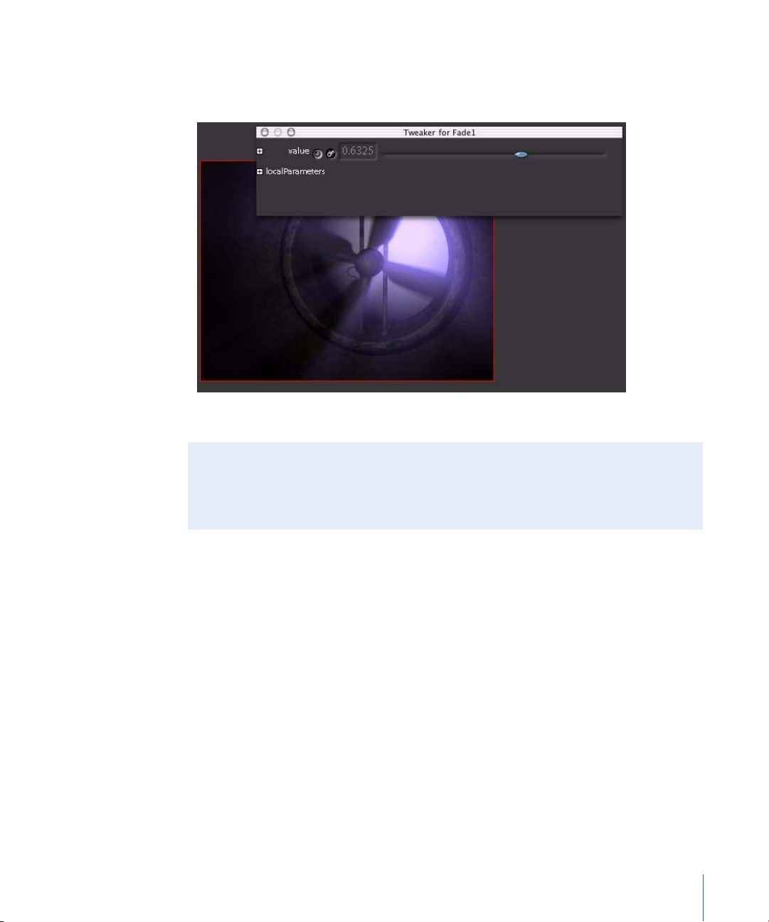
To open a floating Tweaker window:
m
Select the node you want to tune and press Control-T. A movable, floating Tweaker
window for the node appears.
Note: To save your window settings for later use, choose File > Save Interface Settings.
OS Window Functions
Shake responds to OS windowing, so you can resize the entire window, expand it to
full screen, or stow it as an icon by clicking the standard buttons in the upper-right
corner of the Shake Viewer title bar.
Menus and the Title Bar
This section discusses the Shake title bar and the Shake, File, Edit, Tools, Viewers,
Render, and Help menus.
Title Bar Information
The title bar of the full Shake window displays the current version of Shake, the name
of the currently open script, and the current proxy resolution in use.
Chapter 1 An Overview of the Shake User Interface 31
Page 32

Shake Menu (Mac OS X Only)
The following table shows the Shake menu options. The Shake menu appears only in
the Macintosh version of Shake.
Menu Option Description
About Shake Displays the Shake version number and copyright information.
Services Services provide a quick way to perform tasks with several
applications.
Hide Shake (Command-H) Hides Shake. To show Shake again, click the Shake icon in the Dock.
Hide Others (Option-OptionCommand-H)
Quit Shake Quits the Shake application.
Hides all running applications other than Shake. To show the
applications again, choose Shake > Show All.
File Menu
The following table shows the File menu options.
Menu Option Description
New Script
(Command-N or Control-N)
Open Script
(Command-O or Control-O)
Import Photoshop File Imports a Photoshop file. If the Photoshop file contains multiple
Reload Script Reloads the script listed in the title bar.
Add Script Opens the Load Script window. Adds a second set of nodes to
Save Script
(Command-S or Control-S)
Save Script As (Shift-CommandS or Shift-Control-S)
Save Selection As Script Saves the currently selected nodes in the Node View as a separate
Deletes all nodes currently in the Node View. (You can also press
Command-A or Control-A in the Node View to select all nodes and
then press Del.)
Opens the Load Script window. The script selected in the Browser
replaces what is already in the Node View. You can also use the
Load button in the title bar.
layers, you can import the layers as separate FileIn nodes that are
fed into a MultiLayer node, or as a single, composited image by
using a normal FileIn node.
those currently in the Node View. The added nodes are renamed if
a naming conflict arises. (For example, FileIn1 becomes FileIn2 if
FileIn1 already exists.) Global settings are taken from the added
script, as is the new script name.
Saves the script without prompting you for a script name (if you
have already saved). You can also use the Save button in the title
bar.
Opens the Save Script window. Enter the new script name, and
click OK to save the script.
script.
32 Chapter 1 An Overview of the Shake User Interface
Page 33

Menu Option Description
Recover Script (Shift-CommandO or Shift-Control-O)
Load Interface Settings Opens the Load Preferences From window. Select an interface
Save Interface Settings Opens the Save Preferences To window. This lets you save the
Flush Cache When you choose Flush Cache, all appropriate images are copied
Purge Memory Cache Similar to the Flush Cache command, but the memory cache is
Recent Scripts Lists the last five scripts you worked on. Choosing a script from this
Exit (Linux only) Exits the program. You can also use the standard OS exit buttons in
Loads the last autoSave script and is usually done when the user
has forgotten to save a script and quits Shake, or when Shake has
unexpectedly quit. The script is found under $HOME/nreal/
autoSave. (The $HOME directory is your personal Home directory,
for example, the /Users/john directory.)
If you have environment variables set, you can launch Shake on the
command line with the same option using -recover:
shake -recover
For more information on environment variables, see
“Customizing Shake.”
settings file from disk, and click OK to load the file.
various default Shake settings, including your window layout to a
file in your $HOME/nreal/settings file.
If you call it defaultui.h, it is automatically read next time you
launch Shake. You can save the settings file anywhere, but it is not
read automatically unless the file is in the settings directory.
from the memory cache to the disk cache (depending on how the
cacheMode parameter is set), but the memory cache is not cleared.
This command is similar to what Shake does when you quit (the
delay that occurs when you quit is Shake flushing the memory
cache to disk).
cleared afterwards. This is useful if most of your RAM is filled with
cache data, and you want to free it up to create and play a Flipbook
without needing to exit Shake first in order to clear the memory
cache.
The cacheMode parameter in the Globals tab controls whether or
not images in the cache are used (regardless of whether they are
coming from the disk or memory).
list opens it within Shake.
the upper corner of the interface.
Chapter 14,
Chapter 1 An Overview of the Shake User Interface 33
Page 34

Edit Menu
The following table shows the Edit menu options.
Menu Option Description
Undo (Command-Z or
Control-Z)
Redo (Command-Y or Control-Y)
Find Nodes (Command-F or
Control-F)
Undoes previous commands; up to 100 levels of undo. Layout,
viewing, and parameter changes are saved in the Undo list. You can
also click the Undo/Redo button.
You can change the amount of undo/redo levels in your ui.h file.
enus and the Title Bar” on page 31 for more information. If
See “M
you do an Undo and you have not changed anything, click Redo to
go back to your previous settings.
Opens the Select Nodes by Name window that allows you to
dynamically select nodes that match your criteria in the search
string.
• Select by name. Nodes that match the search string are
immediately activated. For example, if you enter f, FileIn1 and
Fade1 are selected. If you enter fi, just FileIn1 is selected.
• Select by type. Select nodes by type. For example, enter Move,
and all Move2D and Move3D nodes are selected.
• Select by expression. Allows you to enter an expression. For
example, to find all nodes with an angle parameter greater than
180, enter:
angle>180
• Match case. Sets case sensitivity.
Tools Menu
The Tools menu provides a menu listing for each of the nodes in the Tool tabs (for
example, Image, Color, Filter, and so on). You can also right-click a tab to display the
tools list. More information about each of these nodes is available in Part II of this
manual.
34 Chapter 1 An Overview of the Shake User Interface
Page 35

Viewers Menu
The following table shows the Viewers menu options.
Menu Option Description
New Viewer Creates a new Viewer in the Viewer area, and automatically
stretches it to fill the Viewer area. While in a Viewer, you can also
right-click and select New Viewer, or press N.
Spawn Viewer Desktop Launches a floating Viewer window that can be moved
independently of the interface. The Viewer Desktop is ideal for
dual-monitor setups.
Render Menu
The following table shows the Render menu options. For more information on
rendering, see Chapter 12, “Rendering With the FileOut Node,” on page 333.
Menu Option Description
Render Flipbook Renders a Flipbook of the current Viewer. Opens the Flipbook
Render Parameters window, which allows you to override the
Global parameters (if necessary). To cancel the render, press Esc
(Escape) when in the Flipbook window.
Render Disk Flipbook Mac OS X only. Launches a disk-based Flipbook into QuickTime.
This has several advantages over normal Flipbooks. It allows for
extremely long clips, allows you to attach audio (loaded with the
Audio Panel in the main interface), and lets you write out the
sequence as a QuickTime file after viewing, bypassing the need to
render the sequence again. For more information, see “C
Disk-Based Flipbook” on page 326.
Render FileOut Nodes Renders FileOut nodes in the Node View. In the Node View, press F
to frame all active nodes. You have the option to render only the
active FileOut nodes, or all FileOut nodes.
Render Cache Nodes Immediately caches sections of the node tree where Cache nodes
have been inserted. This command lets you cache all Cache nodes
in the Node View over a specific duration. For more information on
using Cache nodes, see Chapter 13, “Image C
Render Proxies Renders your proxy files for your FileIn nodes, and leaves your
FileOuts untouched. For more information on proxies, see “U
Proxies” on page 137.
aching,” on page 343.
reating a
sing
Script Management
The following section discusses the buttons in the upper-right corner of the Shake
interface, which let you Load and Save scripts, undo and redo changes you’ve made,
and control when and how the Viewer updates the images generated by your script.
Chapter 1 An Overview of the Shake User Interface 35
Page 36

To load or save a Shake script:
m
Click Load or Save to open the Load Script window, or to save the current script with
the same name.
You can also press Command-S or Control-S to save the script quickly. If the script is not
yet named, the Save Script window opens.
To save a script with a new name:
m
Choose File > Save Script As, and enter a new file name in the Save Script window.
To reload the same script:
m
Choose File > Reload.
The script that appears in the Shake title bar is reloaded.
Customizing AutoSave
A backup script is stored automatically every 60 seconds in your $HOME/nreal/
autoSave directory. The last saved script can be accessed with the File > Recover
menu command (shake -recover in the Terminal), or browsed to under the Directories
pull-down menu in the File Browser.
The backup time interval can be changed in your ui.h files in include/startup/ui/
myPreferenceFile.h. Enter the following line (with the desired time interval, in seconds,
in place of the “60”):
script.autoSaveDelay = 60;
Four other autosave behaviors can be customized within a .h preference file in the
include/startup directory:
• script.autoSaveDirectory: Setting a directory with this declaration overrides the
default behavior of placing autosave scripts in ~/nreal/autosave/.
• script.autoSavePrefix: Defines text to be prepended to autosave script names.
• script.autoSaveNumSaves: Sets the total number of autosave scripts to be saved.
To undo or redo, do one of the following:
m
Click the Undo or Redo button.
Redo
Undo
m
Press Command-Z or Control-Z to undo, or press Command-Y or Control-Y to redo.
36 Chapter 1 An Overview of the Shake User Interface
Page 37

By default, there are 100 steps of undo and redo in Shake.
Changing the Possible Levels of Undo
To change the level of undos, enter the following line (with your desired number of
undos in place of the “100”) in one of your ui.h files:
gui.numUndoLevels = 100;
For more information, see Chapter 30, “Installing and Creating Macros,” on page 905.
Update
The Update button controls what is updated in the Viewer, and when. The Update
button has three modes:
• Always: Updates the Viewer with every change that’s made to a parameter, and
every time you move the playhead in the Time Bar.
• Manual: The scene is not updated until you do one of the following:
• Click Update.
• Click the left side of a node in the Node View.
• Press the U key.
• Release: Waits until you finish adjusting a parameter, or moving the playhead in the
Time Bar, before updating the image in the Viewer.
By default, clicking Manual once toggles this setting to Always. Click and hold this
control to see the pop-up menu, from which you can choose Always, Manual, or Release.
Proxy
The proxy button, labeled “Base,” allows you to quickly get to one of your four proxy
settings.
Click Base once to toggle to P1. Click and hold the Base button for other proxy options.
For more information on proxies, see Chapter 4, “U
Chapter 1 An Overview of the Shake User Interface 37
sing Proxies,” on page 137.
Page 38
The File Browser
The File Browser is an interactive browser that serves many purposes. It lets you
navigate the local volumes (both fixed and removable media) on your computer, or
remote volumes over your network. You use it to open or save scripts, load images via a
FileIn node, and to load and save lookup files and expressions.
Using the File Browser, image sequences can be listed either as a long list of individual
files or as a single object. You can bookmark favorite directories. You can also use it to
create and delete directories, and delete files directly in the Browser.
Opening the File Browser
There are several operations that open the File Browser.
To open the File Browser, do one of the following:
m
Create a FileIn or a FileOut node.
m
Click the Load Script button, located in the upper-right section of the Shake interface.
m
Click the Save Script button, located in the upper-right section of the Shake interface.
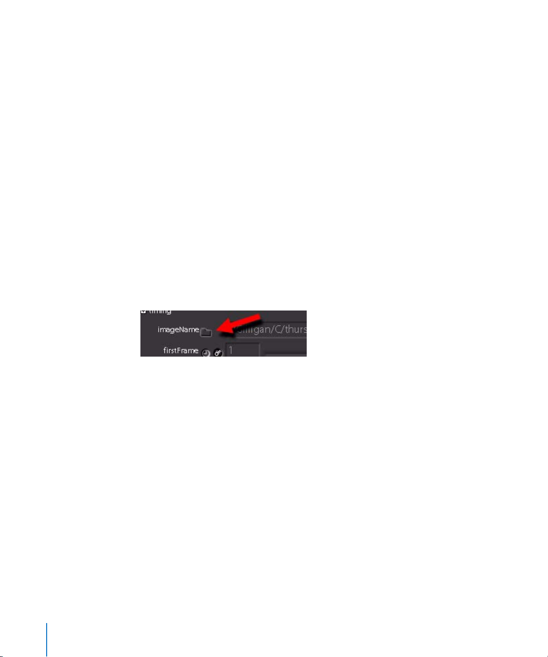
m
To open the File Browser from an existing FileIn or FileOut node (for example, if the
source media becomes disconnected), click the folder icon next to the file path in the
Parameters tab.
38 Chapter 1 An Overview of the Shake User Interface
Page 39

The Browser opens. If you’re using Mac OS X, this window appears very different from
the standard file navigation sheet, but it has much of the same functionality, and
includes additional options that are particularly useful to Shake projects.
Navigating in the File Browser
There are several ways you can navigate to the directory you need using the File
Browser:
Using the File List
A list of directories and files appears in the center of the File Browser. You can doubleclick any directory in this list to make it into the current directory. The following list of
controls lets you navigate the volumes accessible to your computer.
Icon, Button, or Key Description
Indicates a folder.
Indicates a drive.
Takes you to the last viewed directory.
Takes you up one directory. You can also press Delete (Macintosh)
or Backspace (Linux).
Chapter 1 An Overview of the Shake User Interface 39
Page 40

Icon, Button, or Key Description
Up Arrow/Down Arrow key Moves up and down in the list.
Any letter key Once you have clicked in the file listings, press a letter key on the
keyboard to jump to the next occurrence of a file or directory that
starts with that letter.
Using the Pull-Down Menu at the Top
The pull-down menu reveals the entire directory tree, including your root directory, the
directory you launched Shake from, the $HOME directory, the Shake installation, and
any favorite directories you have entered. This menu also automatically lists recently
visited directories.
Using a File Path
You can also type an entire path, with or without the file name itself, into the File Name
field at the bottom of the Browser.
You can format absolute file paths in any of several styles:
• /my_proj/my_directory/my_file.iff
• /d4/my_proj/my_directory/my_file.iff
• //MyMachine/D/my_proj/my_directory/my_file.iff
Enable/Disable Local File Paths
The Relative Path control, to the left of the Add to Favorites control in the File Browser,
gives you the option to enter a relative file path into the File Name field.
Enable local
file paths.
Disable local
file paths.
Relative file paths can take one of two forms:
• ./myDirectory/myFile/
• ../myDirectory/myFile/
Adding Directories to the Favorites List
If there are one or more directories with content you frequently need to access, you can
add them to the Favorites list. The Favorites list is a customizable list of directories that
you can add to at any time. You can explicitly add directories to the list in two ways:
Note: As of Shake 4, entries you add to the Favorites list are permanent.
To add an entry to the Favorites list:
1 Open the File Browser.
40 Chapter 1 An Overview of the Shake User Interface
Page 41

2 Click the Bookmark button.
The currently open directory is added to the Favorites list. All favorite directory paths
you add are saved in the favoritePaths.h file, located in the username/nreal/settings/
directory. By default, the favoritePaths.h file contains:
• Your home directory
• The nreal directory
• The Shake application directory
When you add more directories to the Favorites, they’re automatically appended to the
code in the favoritePaths.h file. For example, if you add following directory to the
Favorites:
/Users/MyAccount/Media/
The resulting favoritePaths.h file looks like this:
// User Interface settings
SetKey(
"globals.fileBrowser.favorites", "/;$HOME;/Users/MyAccount//nreal/;/
Applications/shake-v4.00.0201/;/Applications/shake-v4.00.0201/doc/pix;/
Users/MyAccount/Media/;"
);
Note that each directory path is separated by a semicolon. MyAccount is the name of
the user directory.
To remove directories from the Favorites list:
1 Open the favoritePaths.h file (located in the /nreal/settings/ directory).
2 Delete the paths you want to remove from the Favorites list, and save the file.
You can also instruct Shake to look in certain directories when you start the software,
using the following ui.h settings. Each listing is for a type of file—images, scripts,
expressions, and so on. Note the slash at the end of the path:
gui.fileBrowser.lastImageDir= “/Documents/my_directory/”;
gui.fileBrowser.lastScriptDir= “$MYPROJ/shakeScripts/”;
gui.fileBrowser.lastExprDir= “//Server/shakeExpressions/”;
gui.fileBrowser.lastTrackerDir= “$MYPROJ/tracks/”;
gui.fileBrowser.lastAnyDir= “/”;
For more information on a ui.h file, see Chapter 14, “Customizing Shake,” on page 355.
Selecting Files
If you’re selecting one or more files for a FileIn operation, you can select them in
several ways.
Chapter 1 An Overview of the Shake User Interface 41
Page 42
To select single files, do one of the following:
m
Double-click the file.
m
Press the Up Arrow or Down Arrow, then click OK (or press Return).
m
Press the first letter of the file you want. Press it again to jump to the next file that
starts with that letter. Click OK (or press Return).
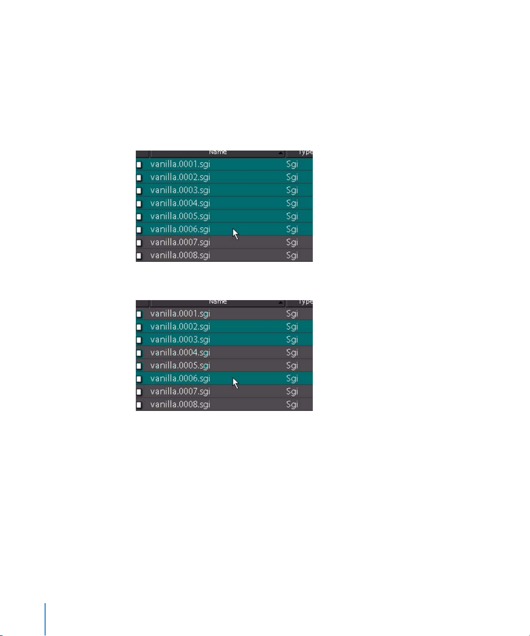
To select multiple files in the same directory, do one of the following:
m
To select multiple files, drag to select the files, then click OK.
m
To select multiple individual files, press Shift and select the files.
To select multiple images in different directories, do one of the following:
m
Click Next in the Browser to load the current image or images and keep the Browser
open to continue to add files. When you have reached the last file, click OK. At any time
in this process, the Node View may be accessed to examine FileIn nodes.
m
Select one or more files, and press the Space bar to add them to an invisible queue of
files to be added to your script, without closing the File Browser. Once you click OK,
every file in this invisible queue is added to the currently open script.
Viewing Controls
There are several tools to help you identify files in the Browser.
42 Chapter 1 An Overview of the Shake User Interface
Page 43
The File List
Click the title of a column to arrange the list according to that type of information. For
example, click Modified to list files by creation date. Click Modified again to reverse the
order of information.
Toggle Buttons
The following buttons also change what is listed in the Browser:
Button Description
Short Listing Lists only file names, type, and size.
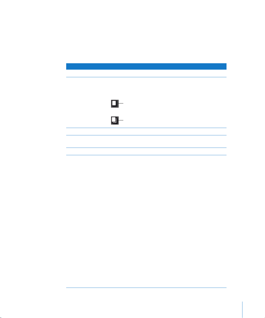
Sequence Listing Toggles the listing of an image sequence as one listing or as
several. To read in the entire sequence, ensure that this Sequence
Listing is enabled. These icons signify single or sequence files:
Indicates a single file.
Indicates an image sequence.
Images Only Lists only recognized image types.
Show Exact Sizes Shows the exact file size in kilobytes, rather than rounded off in
megabytes.
Show Full Path Lists the entire path of the selected file.
Filter Filters out information.
Use * and ? as your wildcards:
Wildcard
*
Example
*.cin
*.cin.*
*.cin*
image.*.tga
Wildcard
?
Example
?.cin
??.iff
a.???
image.????.iff
image.???1.iff
Means
Any set of characters for any
length.
Lists
a.cin, image.cin, image.0001.cin,
...
a.cin.0001, image.cin.hr
a.cin, image.0001.cin,
image.cin.0001
image.1.tga, image.10.tga,
image.0100.tga
Means
Any character in that single
position.
Lists
a.cin, 1.cin
ab.iff, 01.iff
a.cin, a.iff, a.tga
image.0001.iff, image.9999.ifff
image.0001.iff, image.0011.iff,
image.1111.iff
Chapter 1 An Overview of the Shake User Interface 43
Page 44

Updating the File Browser
Click the Update button to refresh the listing of the current directory in case files have
been added or deleted while the File Browser has been open.
Specifying Media Placement
Three buttons let you set the first frame at which new media is placed when it’s read
into your Shake script. This affects the timing of the media inside of your script, and can
be seen in the Time View tab.
• frame 1: The first frame of media is placed at the first frame of your script.
• seq. start: The first frame of media is placed to the corresponding frame of the script,
depending on its frame number. If you import frames 9-50 of an image sequence,
the first frame of media appears at frame 9 of the Time View.
• current frame: The first frame of media is placed at the current position of the
playhead.
Additional Controls for Image Output
When you’re writing out a file using the FileOut node, you also use the File Browser to
select a directory and enter the file name for the rendered output. For more
information about exporting media from Shake, see Chapter 12, “Rendering With the
FileOut Node,” on page 333.
File Management Controls
There are additional file management controls that are primarily useful when exporting
(“writing out”) media.
Button Description
Creates a new directory using the current path.
Deletes currently selected files and directories.
Naming Files for Output
If you are writing out an image sequence, be sure to insert a # or an @ sign where you
want the frame number to go in the name. When you are finished, click OK to validate.
44 Chapter 1 An Overview of the Shake User Interface
Page 45

The following is a table of examples.
Files Shake Notation
image.0001.cin, image.0002.cin image.#.cin
image.1.tif, image.2.tif image.@.tif
image.iff.0001, image.iff.0002 image.iff.#
image1.tga, image2.tga image@.tga
image.001.tga, image.002.tga image.@@@.tga
image.01, image.02 image.@@
Using and Customizing Viewers
Shake displays the currently selected image for your project in the Viewer, located in
the Viewer workspace at the upper-left quadrant of the interface. Additional controls in
the Viewer shelf at the bottom of the Viewer workspace let you customize how the
image is displayed. For example, you can view each channel of an image individually.
You can also change the Gamma of the Viewer to simulate how the image might look
on other output devices. Other tools such as the Histogram and Plot Scanline Viewer
scripts can help you analyze your image.
Image from The Saint provided courtesy of Framestore CFC and
Paramount British Pictures Ltd.
Some nodes feature onscreen controls (which also appear in the Viewer) that let you
make adjustments to an image. For example, the Move 2D and Rotate nodes display
transformation controls you can drag to manipulate the image directly in the Viewer.
Other nodes make additional tools available in the Viewer shelf. For example, the
RotoShape node places drawing and editing tools in the Viewer shelf that let you create
and manipulate shapes directly in the Viewer.
Chapter 1 An Overview of the Shake User Interface 45
Page 46
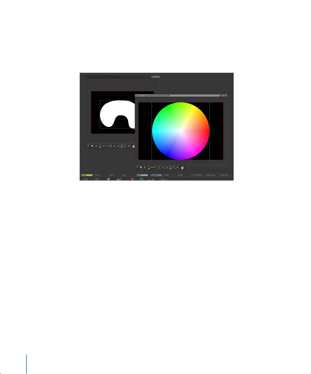
Using Multiple Viewers
You can create as many Viewers within the Viewer workspace as you need. Each
additional Viewer you create appears within the Viewer workspace area, and each
Viewer can be set to independently display any image channel from any node in the
current node tree. Each Viewer has its own Viewer shelf with its own controls, and each
Viewer you create has two buffers that you can use to compare images.
Note: Because each Viewer has two buffers, using multiple Viewers at once can
consume a lot of RAM, depending on the resolution of the images you’re working with.
When additional Viewers are displayed, each Viewer is updated dynamically. You can
use this capability to simultaneously view the results of a downstream node in one
Viewer, while also seeing the image from an upstream node in another Viewer. A good
example of this is when you’re refining a key in one Viewer, while watching the effect
this has on the finished composite in another.
To create additional Viewers:
1 Position the pointer anywhere within the Viewer area.
2 Do one of the following:
• Press N.
• Right-click, then choose New Viewer from the shortcut menu.
• Choose Viewers > New Viewer to create a new Viewer.
A new Viewer named “Viewer2” is created above Viewer1 in the Viewer workspace.
Additional Viewers are numbered in the order in which they’re created.
46 Chapter 1 An Overview of the Shake User Interface
Page 47
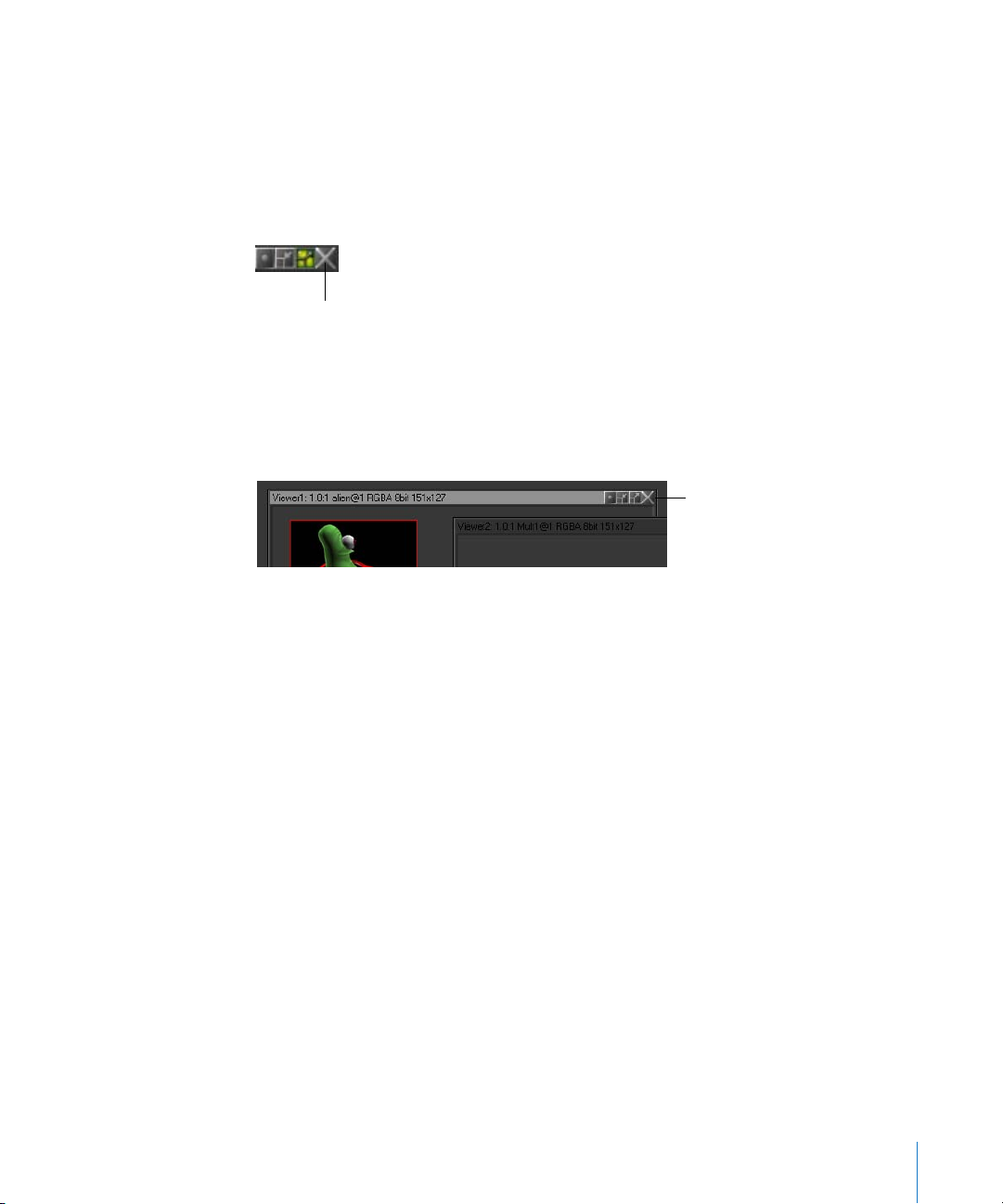
Note: Each Viewer you create uses additional memory, so you may want to close
higher-resolution Viewers when rendering. Also, more open Viewers can slow the
display rate due to the increased processing demands of updating each Viewer
simultaneously.
To close a Viewer:
m
Click the Close Window button in the selected Viewer’s title bar.
Close Window button
When you close a Viewer, you release whatever RAM that Viewer was utilizing.
To bring a Viewer to the foreground:
m
Click anywhere within that Viewer.
When a Viewer is selected, its title bar is highlighted.
This viewer is selected.
To display the image from another node in a Viewer:
1 Double-click anywhere within the Viewer you want to use.
Its title bar becomes highlighted to show that it is selected.
2 Do one of the following:
• Double-click a node in the Node View to display its image in the currently selected
Viewer and to display its parameters in the Parameters1 tab.
• Click the left side of a node to display its image in the currently selected Viewer
without loading its parameters into the Parameters tab.
Chapter 1 An Overview of the Shake User Interface 47
Page 48

When a node is loaded into the Viewer, an indicator appears on the left side of the
node. Additionally, a number and a letter appear below it, specifying which Viewer and
compare buffer that node’s image occupies.
This node is displayed in
viewer 2, buffer A
This node is displayed in
viewer 1, buffer A
To collapse a node to a minimized state:
m
Click the Iconify Viewer button in the Viewer title bar to minimize its size.
To expand a node from a minimized state:
m
Click the Iconify Viewer button of the minimized Viewer to restore it to its original size.
Iconify Viewer button
Minimized Viewers are only as large as the title and the upper-right window controls.
To resize a Viewer, do one of the following:
m
Drag a Viewer’s left, right, or bottom side.
48 Chapter 1 An Overview of the Shake User Interface
Page 49

m
Drag a Viewer’s bottom-right corner to resize its width and height simultaneously.
To resize a Viewer to fit the image within:
m
Click the Fit Viewer to Image button in the Viewer title bar.
Fit Viewer to Image button
To lock a Viewer to the full size of the Viewer workspace:
m
Click the Grip to Desktop button in the Viewer title bar.
Grip to Desktop button
The full-size Viewer now obscures any other Viewers underneath it, and resizes itself to
match the total size of the Viewer workspace. To see other Viewers underneath, click
the Grip to Desktop button again to release the Viewer, then resize it or move it to
make room in the Viewer workspace for the other Viewers.
Note: By default, the first Viewer that was created along with your project is locked to
the full size of the Viewer workspace.
To exand the Viewer workspace to the full size of the Shake window:
m
Press the Space bar.
Afterwards, you can press the Space bar again to reset the Viewer workspace to its
original size.
Chapter 1 An Overview of the Shake User Interface 49
Page 50

To reposition all Viewers within the Viewer workspace at once:
m
Click the middle mouse button anywhere in the Viewer workspace outside of any of
the Viewers, then drag to move all of the Viewers around the workspace.
To create a separate Viewer workspace for use on a second monitor:
m
Choose Viewers > Spawn Viewer Desktop. The second monitor must be run from the
same graphics card as the primary monitor.
To help prevent accidentally rendering an enormous image (for example, if you enter
200 into your zoom parameter instead of 20), the Viewer’s resolution is limited to 4K.
This limit is configurable. The Viewer resolution has no effect on rendered images—it
only crops the view in the Shake interface to the set resolution.
Warning: If you get strange Viewer behavior, delete the Viewer (right-click, then
choose Delete Viewer from the shortcut menu), and create a new Viewer.
Looking at Images in a Viewer
To load a node into the current Viewer, click the left side of the node. The green Viewer
indicator appears. Double-click the node to simultaneously load the node’s parameters
in the Parameters tab.
In the following image, the Grad node is loaded into the Viewer.
Viewer indicator: Click once to display
node in Viewer. Double-click to load
node parameters.
50 Chapter 1 An Overview of the Shake User Interface
Page 51

The information (node name, channels, bit depth, size, and so on) for the selected node
appears in the Viewer title bar. When the Grad node is loaded into the Viewer, the
following appears in the Viewer title bar.
Viewer title bar
Note: The channels displayed in the Viewer are the non-zero channels. Non-zero
channels are not the same as active channels. For example, a Color node set to black
(black and white values are zero) displays the alpha channel (A) in the Viewer title bar:
When the Color node is adjusted toward gray (the black and white values are no longer
zero), the black, white, and alpha channels (BWA) are displayed:
Every Viewer has the built-in capability to analyze color.
Chapter 1 An Overview of the Shake User Interface 51
Page 52

To quickly analyze colors in the Viewer:
m
Click and scrub with the mouse in the Viewer to display the X, Y, R, G, B, and alpha
values in the Viewer title bar.
These values are also displayed in the Info field in the bottom-right corner of the
interface. You can also use the Pixel Analyzer and Color Picker windows to analyze this
data with more extensive options.
Note: To display the values in the Terminal window that launched Shake, press Control
and scrub in the Viewer.
Suspending Rendering and Viewer Redraw
There are two ways you can suspend rendering the node tree. This can help if you’re
making adjustments to a render intensive node and you don’t want to wait for the
image to render and display in the Viewer every time you make an adjustment.
To immediately stop rendering at any time:
m
To stop any processing at any time, press Esc.
Rendering is suspended until another operation occurs that requires rendering.
To suspend rendering and redraw in the Viewer altogether:
m
Change the Viewer’s update mode to Update Off via the Update Mode control in the
Viewer shelf.
Rendering is suspended until the Viewer’s update mode is changed to Update On or
Progress.
Controls in the Viewer Shelf
The Viewer shelf has many controls that let you customize how images are displayed in
the Viewer. These controls can be used directly, but many Viewer controls also
correspond to shortcut menu items and keyboard shortcuts with the same function.
52 Chapter 1 An Overview of the Shake User Interface
Page 53
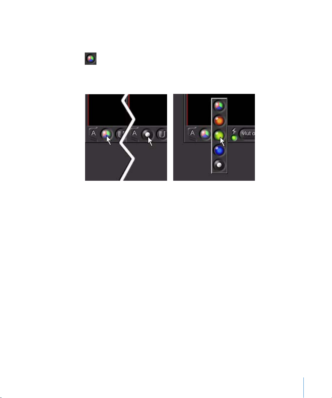
To use the two different click-and-hold button behaviors:
m
Click the View Channel button in the Viewer to toggle between the RGB and the alpha
views.
m
Click and hold the View Channel button to open a pop-up menu from which you can
choose a specific channel view.
Click. Click and hold.
You can override the default channel display progression when the View Channel
button is clicked. For example, clicking the button in RGB view displays the alpha view.
When you click again, the RGB view is displayed.
To go from RGB to red to alpha channels:
1 Command-click or Control-click and hold the View Channel button, then select the Red
Channel button.
2 Command-click or Control-click and hold the View Channel button, then select the
Alpha Channel button.
When you click the View Channel button, you now toggle through RGB, red, alpha, and
back to RGB.
3 To save this behavior, choose File > Save Interface Settings.
Note: You can cycle through some Viewer functions using number keys. Press 2 to
cycle forward through the channel views, and press Shift-2 to toggle backward through
the channel views. Press 1 to toggle between the A and B compare buffers.
Chapter 1 An Overview of the Shake User Interface 53
Page 54

The following table shows the Viewer buttons, the keyboard or hot key shortcuts, and
describes the button functions.
Button Shortcut Description
Pointer Drag the pointer in the Viewer to display the X
and Y position values, and the RGBA color
values in the Viewer title bar. The values are
also displayed in the Info field.
Iconify Viewer Stows the current Viewer.
Fit Viewer to
Image
Grip to
Desktop
Close Window Right-click menu
Buffer Tabs 1 You can have two different buffers in a Viewer
View Channel R, G, B, A, C;
Update Mode–OnRight-click menu;
Update Mode–
Progress
Update Mode–
Off
Control-F Fits the Viewer to the image.
Shift-F Fits the frame to the Viewer workspace. When
enabled, the Viewer “sticks” to the workspace.
You can then resize the workspace and the
Viewer expands to match.
Deletes the Viewer. (A good strategy if a Viewer
> Delete
2/Shift-2 cycle;
right-click menu
3/Shift-3
Right-click menu;
3/Shift-3
Right-click menu;
3/Shift-3
is misbehaving. Press N to create a new
Viewer.)
to compare images. See “U
Buffers” on page 57.
Toggles through the color channels: RGB
(color), red, green, blue, alpha.
Update mode that displays a rendered image
only after it is finished rendering. This is for
relatively fast renders.
Scrolling update mode that displays each line
(starting from the bottom) as the image
renders. Used for slower renders.
The Viewer does not update. Use this to load
an image into a Viewer, then switch to the
second buffer (see below) and do some
changes. You can then compare it with the
original.
sing the Compare
54 Chapter 1 An Overview of the Shake User Interface
Page 55

Button Shortcut Description
Incremental
Update
VLUT Off Right-click menu VLUTs (Viewer lookup tables) differ from
Truelight VLUT Right-click menu The Truelight VLUT combines monitor
Gamma/Offset/
LogLin VLUT
Viewer DOD Right-click menu Turns on Region of Interest (ROI) rendering
Viewer Script–
Off
Right-click menu The Gamma/Offset/LogLin VLUT allows you to
Right-click menu;
4/Shift-4
Updates the changing portion of the image.
For example, if Toggle Incremental Update is
disabled and you composite a 10 x 10-pixel
element on a 6K plate and pan the element,
the entire 6K plate updates. When enabled,
only the 10 x 10-pixel area is updated. To fix
this, turn off the Incremental Update and
adjust again—the glitches are corrected. This
button has no effect on the output file or
batch rendering speed, only on the image in
the Viewer.
Viewer scripts in that you can scrub from the
unmodified plate. See “V
Scripts, and the Viewer DOD” on page 61.
calibration with the previsualization of film
recorders and other output devices. See
iewer Lookups, Viewer Scripts, and the
“V
Viewer DOD” on page 61.
apply different quick lookups to your image.
iewer Lookups, Viewer Scripts, and the
See “V
Viewer DOD” on page 61.
(limits your rendering area). See “V
Lookups, Viewer Scripts, and the Viewer DOD”
on page 61.
See “V
iewer Lookups, Viewer Scripts, and the
Viewer DOD” on page 61.
iewer Lookups, Viewer
iewer
Viewer Script–
Aperture
Markings
Viewer Script–
Plot Scanline
Viewer Script–
Histogram
Chapter 1 An Overview of the Shake User Interface 55
Right-click menu Applies aperture markings. You can also right-
click the Viewer Script button, then choose
Aperture Markings. See “V
Viewer Scripts, and the Viewer DOD” on
page 61.
Right-click menu Applies a plot scanline. You can also right-click
the Viewer Script button, then choose Plot
Scanline. See “V
and the Viewer DOD” on page 61.
Right-click menu Applies a Histogram. You can also right-click
the Viewer Script button, then choose
Histogram. See “V
Scripts, and the Viewer DOD” on page 61.
iewer Lookups, Viewer Scripts,
iewer Lookups,
iewer Lookups, Viewer
Page 56

Button Shortcut Description
Viewer Script–
Z Channel
Viewer Script–
Superwhite/
Subzero
Viewer Script–
Frames/
Timecode
Right-click menu Views the Z channel. You can also right-click
the Viewer Script button, then choose ViewZ.
iewer Lookups, Viewer Scripts, and the
See “V
Viewer DOD” on page 61.
Right-click menu Displays superwhite and subzero pixels. You
can also right-click the Viewer Script button,
then choose Float View. See “V
Viewer Scripts, and the Viewer DOD” on
page 61.
Right-click menu Displays frames or timecode in the active
Viewer. See “V
and the Viewer DOD” on page 61.
iewer Lookups, Viewer Scripts,
iewer Lookups,
Compare
Mode–No
Compare
Compare
Mode–
Horizontal (Y
Wipe)
Compare
Mode–Vertical
(X Wipe)
Compare
Mode–Blend
(Fade)
Show/Hide
DOD Border
Reset Viewer Home key Centers the image and sets the zoom level to
Fit Image to
Viewer
5/Shift-5 Only one buffer is displayed. See “U
Compare Buffers” on page 57.
5/Shift-5 You can also right-click the Compare Mode
button, then choose Y Wipe. See “U
Compare Buffers” on page 57.
5/Shift-5 You can also right-click the Compare Mode
button, then choose X Wipe. See “U
Compare Buffers” on page 57.
5/Shift-5 You can also right-click the Compare Mode
button, then choose Blend. See “U
Compare Buffers” on page 57.
Right-click menu Displays the green DOD (Domain of Definition)
border and the red frame border. It has no
effect on processing or the rendered image.
1:1.
F Fits the image to the frame. Be careful, since
you may get a non-integer zoom (for example,
instead of 2:1, you get 2.355:1), which may
result in display artifacts. Do not use this
option when “massaging” pixels.
sing the
sing the
sing the
sing the
56 Chapter 1 An Overview of the Shake User Interface
Page 57

Button Shortcut Description
Launch
Flipbook
Broadcast
Monitor
Renders a RAM-based image player.
Left-mouse click: Renders with the current
settings.
Right-mouse click: Displays the Render
Parameters window.
Mirrors the selected node in the Viewer on a
video broadcast monitor.
The broadcast monitor option is only available
in the Mac OS X version of Shake.
For more information, see “V
External Monitor” on page 330.
iewing on an
For a table of additional common buttons related to onscreen controls, see “N
ode-
Specific Viewer Shelf Controls” on page 70.
Using the Compare Buffers
You can use the A and B buffers in the Viewer to load two images at once. The
following example uses two images from Tutorial 5, “Using Keylight,” in the Shake 4
Tutorials book.
To load two images at once into the A and B compare buffers:
1 Using two FileIn nodes, read in two images from the “Using Keylight” tutorial.
The images are located in the $HOME/nreal/Tutorial_Media/Tutorial_05/images
directory.
2 In the Viewer, ensure that buffer A is open.
3 Load one of the tutorial images into the Viewer by clicking the left side of the node.
The Viewer indicator appears on the left side of the node, and the node’s image is
loaded into the Viewer.
Chapter 1 An Overview of the Shake User Interface 57
Page 58
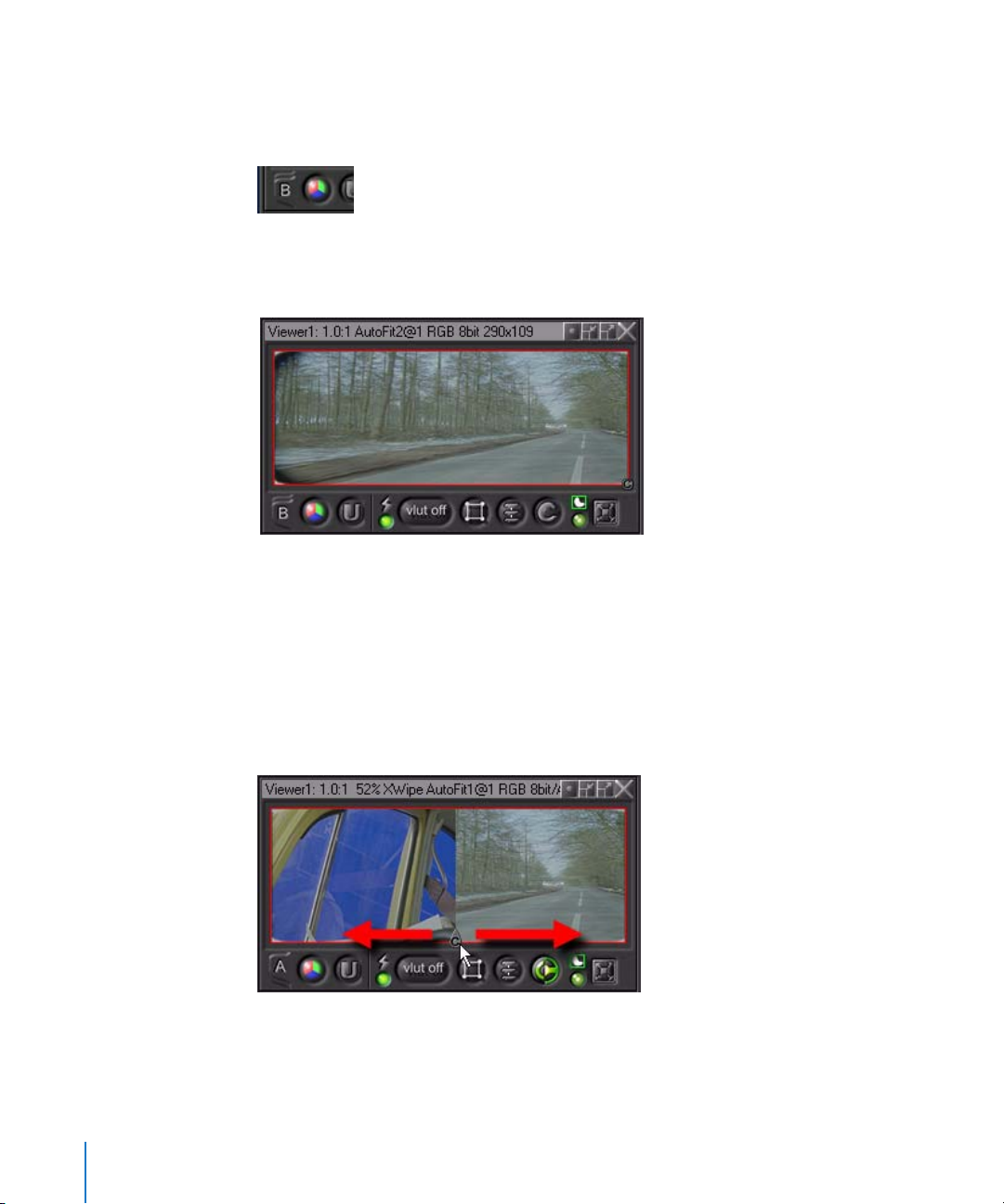
4 To switch to buffer B, click the A tab, or press 1 (above the Tab key, not on the numeric
keypad).
The A tab switches to B when clicked.
5 Load the second image into buffer B by clicking the right side of the image’s node.
6 Press 1 to toggle between buffers. You can also click the A and B tabs.
Images from The Saint provided courtesy of Framestore CFC and
Paramount British Pictures Ltd.
You can also put the Viewer into split-screen mode to more directly compare two
images.
To create a vertical split screen in the Viewer:
m
Drag the Compare control (the small gray “C” the lower-right corner of the Viewer) to
the left.
58 Chapter 1 An Overview of the Shake User Interface
Page 59

The Compare Mode button in the Viewer shelf indicates that you are in vertical
compare mode.
To create a horizontal split screen:
m
Drag the Compare control up on the right highlighted edge.
The Compare Mode button in the Viewer shelf indicates that you are in horizontal
compare mode.
Alternatively, you can toggle between vertical and horizontal split screens by using the
Compare Mode button.
Note: A common mistake is to slide the Compare control all the way to the left or right
(or top or bottom)—one image disappears and only the second image is revealed. The
result is that changes to a node’s parameters don’t update the Viewer. To avoid this,
turn off the Compare Mode to ensure you are looking at the current image.
To turn off split-screen viewing:
m
Click the Compare Mode button in the Viewer shelf.
The split screen is removed and the button is no longer highlighted.
If the Compare Mode button is set to No Compare and the Viewer is still not updating,
make sure that the Update Mode is set to On.
Chapter 1 An Overview of the Shake User Interface 59
Page 60

If the Update Mode is not the problem, check to make sure that the manual Update
button at the top of the interface is not set to “manual.”
60 Chapter 1 An Overview of the Shake User Interface
Page 61
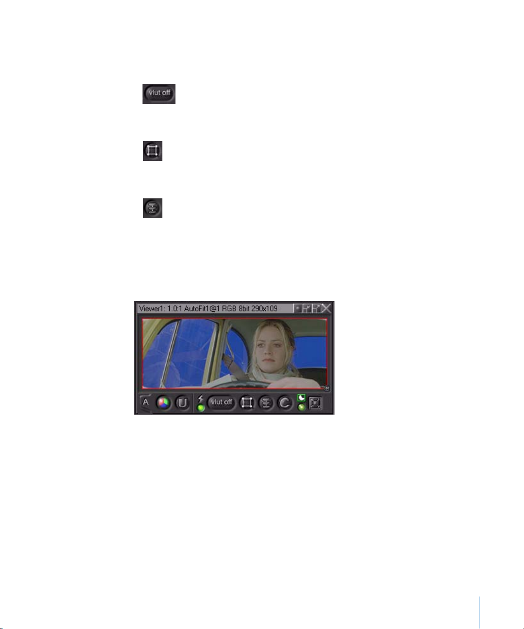
Viewer Lookups, Viewer Scripts, and the Viewer DOD
There are three similar controls that affect how your images are viewed:
• Viewer lookup tables (VLUTs)
• The Viewer DOD
• Viewer scripts
These functions modify the image for efficiency or previsualization purposes, and do
not affect the output image. If necessary, it’s possible to apply these settings to a
render that is launched from the interface.
The following is an example of using a VLUT with a log image.
Chapter 1 An Overview of the Shake User Interface 61
Page 62
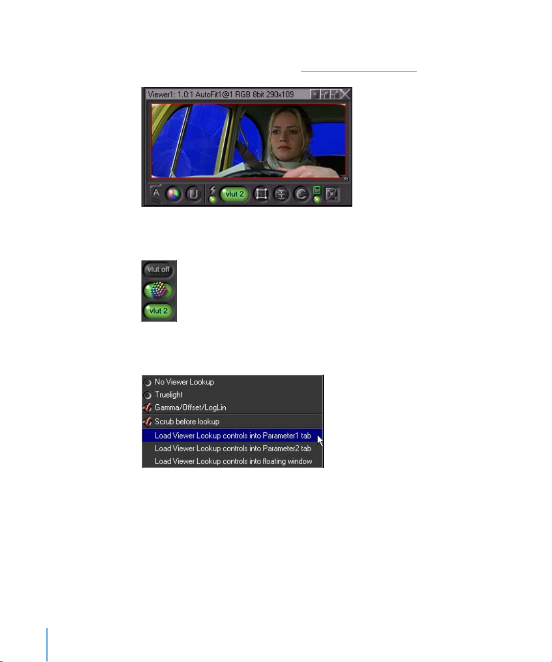
When LogLin conversion is enabled in VLUT 2, you still work on the log image in the
process tree, but you see the linearized plate. (For more information about
logarhtymic-to-linear conversion, see “T
he Logarithmic Cineon File” on page 437.)
To activate the VLUT or Viewer Script controls:
1 Apply your VLUT or script.
2 Right-click the VLUT (Viewer Lookup Table) button and select one of the three Load
Viewer Lookup options.
3 In the designated window or tab (selected in step 2), adjust any necessary parameters.
VLUTs have an additional right-click function to specify whether pixel values are
scrubbed from before or after the VLUT. Right-click and hold the VLUT button, and
enable (or disable) “Scrub before lookup.”
62 Chapter 1 An Overview of the Shake User Interface
Page 63
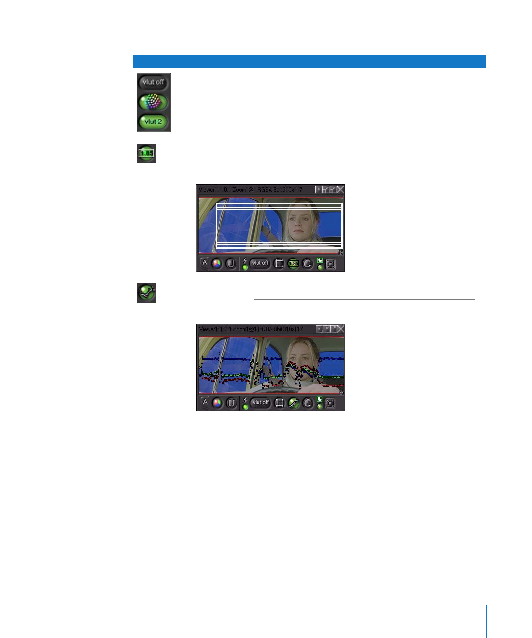
The following table includes the current default scripts and VLUTs.
Button Description
VLUT: Three options let you turn on or off a VLUT for the Viewer.
• By default, the VLUT is turned off.
• A second option lets you use the Truelight VLUT control, combining monitor
calibration with the previsualization of film recorders and other output devices.
• A third option, VLUT 2, allows Gamma, Add, and LogLin operators to be applied to
the Viewer.
Viewer Script–Aperture: Displays a field chart with safe zones. To load script controls
into the Parameters tab, right-click the button, then choose Load Viewer Script
Controls from the shortcut menu.
Viewer Script–Plot Scanline: Displays a plot scanline of your image. For more
information, see “U
on page 674.
sing the PlotScanline to Understand Color-Correction Functions”
Displays pixel values along the horizontal axis (where the light gray line is). The
sample image bluescreen is evenly lit. You can view RGB, A, or RGBA, and calculate
according to color, luminance, or value.
Chapter 1 An Overview of the Shake User Interface 63
Page 64

Button Description
Viewer Script–Histogram: Displays a Histogram of your image.
Viewer Script controls (right-click the Viewer Script button to select Load options):
• ignore: Ignores pixels with a 0 or 1 value.
• maxPerChannel: Pushes the values up on a per-channel basis.
• fade: Fades the display of the Histogram.
The colors are squeezed down in a limited range, an indication that this is probably
a logarithmic image.
Notice the big healthy chunk of blue near the high end. That is good.
Viewer Script–Z Channel: Displays the Z depth of an image either normalized or
between a set range. A very important note: Closer pixels are white, so the image
can fade to infinity (black) without a visual discontinuity.
Viewer Script controls (right-click Viewer Script button to select Load options):
• floatZinA: Puts the Z values in the alpha channel to scrub and retrieve these
values. The values are either Off, the Original values, or Distance (normalized
between 0 and 1). If you have an object that moves from far away toward the
screen over several frames, Original returns your Z values relative to each other;
Normalized indicates only the Z values within that frame.
• zNormalize: Indicates whether the render came from Maya or 3ds max. The
subparameter zInfinity sets the limit at which point pixels are considered infinite,
and are therefore clipped.
• zRangeSource: Evaluates the original values, or the near/far Input values.
64 Chapter 1 An Overview of the Shake User Interface
Page 65

Button Description
Viewer Script–Superwhite/Subzero: Displays pixel values above 1 or below 0 for float
images. The alpha channel is also tested.
Viewer Script controls (right-click the Viewer Script button to select Load options):
• view: This parameter controls how the pixels are displayed:
per channel: Sets subzero pixels to 0, sets pixels between 0 and 1 to 0.5, and pixels
above 1 to 1. This is applied on a per-channel basis.
per image: Turns subzero pixels black, pixels between 0 and 1 gray, and pixels
above 1 to 1. This is applied across the entire image, so if any channel is beyond 0
or 1, it is indicated.
on Image: Mixes the subzero and superwhite pixels back onto the image. The
colors are controlled with the two color controls.
• SubZero Color: Only active when view is set to “on Image,” it indicates the subzero
pixels.
• SuperWhite Color: Only active when view is set to “on Image,” it indicates the
superwhite pixels.
In this example, do the following:
• Read in the saint_bg.@ from the $HOME/nreal/ Tutorial_Media/Tutorial_05/images
directory.
• Apply an Other–Bytes node and a Color–LogLin node.
• Toggle Bytes from 8 to float.
• Apply the Float View Viewer Script. Since LogLin pushes values above 1, the sky
loses its punch when you go back out to Log and you process the image in only
16 bits.
Tree Input Log image LogLin (linear) image
per channel float view per image float view on image float view
The per-channel view indicates that most of the superwhite values are in the blue
channel. The per-image view indicates the dark areas more clearly. The on-image
view codes the highlights yellow and the darks blue.
Chapter 1 An Overview of the Shake User Interface 65
Page 66

Button Description
Viewer Script–Frames/Timecode: Displays frames or timecode in the active Viewer.
To show and modify the frames/timecode display:
• Right-click the Viewer Script button and select timecode, or click and hold the
Viewer Script button and select the Timecode button. By default, timecode is
displayed in the Viewer.
• Right-click the Viewer Script button and select Load Viewer Script into Parameters2
tab. The timecode parameters are loaded into the tab.
• Click the mode pop-up menu to choose Frames, Padded Frames, Timecode, or
Timecode Dropped Frame.
• Use the Time Offset subtree to offset by hours, minutes, seconds, or frames.
• Color: Click the color control to change the color of the text display.
• BgColor: Click the color control to change the color of the timecode display
background box.
• BgOpacity: Controls the opacity of the timecode display background box.
• size: Controls the size of the frames/timecode display.
• xPos: Controls the X position of the frames/timecode display. You can also use the
onscreen controls to reposition the display.
• yPos: Controls the Y position of the frames/timecode display. You can also use the
onscreen controls to reposition the display.
More About Using VLUTs
The VLUTs and the Viewer scripts are similar in that they apply an arbitrary set of
functions that modify the image. A typical example is a color lookup table to
compensate for the display properties of your computer’s monitor.
The key difference is that VLUTs allow you to scrub pixel values from the unmodified
image (this feature can be disabled) whereas you always scrub the modified pixel
values when using Viewer scripts. For example, you may want to work on Cineon plates
in logarithmic space without converting the plates to linear space. However, you want a
rough idea of what the images look like in linear color space. To do this, apply a VLUT
to convert the images to linear space. The results when scrubbing colors in the Viewer
are still derived from the original, unmodified input logarithmic plates, which ensures
accurate processing for your output images.
VLUTs are typically used during color correction, and Viewer scripts are typically used
for unusual operations—for example, when creating an image for stereoscopic viewing.
Both methods let you use any series of pre-made functions.
Shake includes two VLUTs, the Truelight VLUT, and VLUT 2, which can be customized
any way you need. You can also create as many additional VLUTs as you need, for
different situations. You can only turn on one VLUT and one Viewer script at the same
time, but both can be activated simultaneously. To apply multiple color corrections,
build your VLUTs and scripts to have multiple controls.
66 Chapter 1 An Overview of the Shake User Interface
Page 67

Note: The Truelight VLUT control in the Viewer shelf lets you set the Viewer’s lookup
table to use calibration profiles that you can create with the TLCalibrate node, or that
are created using Truelight’s monitor probe. Use the Load Viewer Lookup Controls into
Parameters1 Tab command to make adjustments to the Truelight VLUT parameters. For
more information on using Truelight, see the Truelight documentation, located in the
Documentation folder on the Shake installation disc.
Important: Currently there is no version control of the Viewer script. If you extend the
functionality of existing Viewer scripts that may have been saved in existing Shake
scripts, you should rename the new version of the Viewer script to something other
than the original name.
Using the Viewer’s Domain of Definition (DOD)
The Viewer Domain of Definition (DOD) limits the area of the image that is rendered to
the interior of a user-definable rectangle, in order to reduce the amount of unnecessary
processing. For example, if you are doing a head replacement, you may want to
activate the Viewer DOD and limit the Domain of Definition to a box surrounding just
the head, eliminating the need for your computer to render the rest of the image.
When using the Viewer DOD, keep the following in mind:
• The Viewer DOD limits the rendering area on the Viewer, but does not affect the
output image.
• Display DOD displays the green internal DOD box associated with each node and the
red frame boundary (does not affect processing).
The following image has both the VLUT 2 and the Viewer DOD applied.
Chapter 1 An Overview of the Shake User Interface 67
Page 68

Right-click the Viewer DOD button to access the DOD control options. For example,
using Frame DOD to Viewer (sets the DOD to the Viewer frame), you can zoom in on an
area you want to focus on and limit your DOD to that area. Note that the DOD is not
dynamic, as it would need to constantly recalculate as you pan. For more information,
he Domain of Definition (DOD)” on page 82.
see “T
Creating Your Own VLUTs and Viewer Scripts
The preset examples are stored in the end of the nreal.h file. To roll your own, you first
declare them in a startup directory following the same guidelines as for macros. The
following functions do absolutely nothing:
image ViewerLookup1_(image img)
{
return img;
}
image ViewerScript1_(image img)
{
return img;
}
Next, also in a startup file, hook them into the Viewers:
nfxDefViewerLookup(“Lookup1”, “ViewerLookup1_()”, “default”);
nfxDefViewerScript(“Script1”, “ViewerScript1_()”, “default”);
The first argument (“Lookup1”, “Script1”) is the name of the VLUT/Script as it appears in
the list in the interface. The second arguments (“ViewerLookup1_()”, “ViewerScript1_()”)
are the actual functions they call when activated. These must be declared in a startup .h
file. The third arguments are the optional icon files, relative to the icons/viewer
directory. It is assumed there is an .nri extension and that you also have a focused
version called [icon].focus.nri.
Therefore, if you want to load a button called icons/viewer/vluts/dufus.nri, you also
create a focused version called icons/viewer/vluts/dufus.focus.nri. You then use “vluts/
myVLUT” as your icon name. “default” means it is looking for vlut.@.nri, vlut.@.focus.nri,
vscript.@.nri, and vscript.@.focus.nri (@ = 1, 2, 3, etc.). All paths are relative to icons/
viewer. The icons for Viewer scripts are 30 x 30 pixels, no alpha. The standard VLUT
buttons are 51 x 30 pixels, no alpha. See “Other Macros–VLUT Button” in Chapter 32,
“The Cookbook.” Other macros required to run the VLUT Button macro can be found in
doc/html/cook/macros.
Viewer Keyboard Shortcuts
The following table contains additional Viewer hot keys.
Keyboard Function
NCreate/Copy New Viewer.
FFit Image to Viewer.
68 Chapter 1 An Overview of the Shake User Interface
Page 69

Keyboard Function
Control-F Fit Viewer to Image.
Shift-F Fit Viewer to Desktop.
Alt-drag Pan image.
+ or - Zoom image in Viewer.
Home Reset view.
R, G, B, A, C Toggle Red, Green, Blue, alpha, and Color views.
Also, see the table on page 54 for keyboard equivalents to Viewer buttons.
The Viewer Shortcut Menu
Shortcut menus differ depending on the location of the pointer in the interface, or
what function/button the pointer is on. The following table shows the shortcut menu
commands available in the Viewer.
Menu Option Keyboard Description
Edit Undo Command-Z or
Control-Z
Redo Command-Y or
Control-Y
View Zoom In/Out + or - (next to
the Delete
(Mac) /
Backspace
(Linux) key
Reset View Home Sets the Viewer ratio to 1:1. The Viewer ratio is
Fit Image
to Viewer
Fit Viewer
to Desktop
Fit Viewer
to Image
Render Render
Flipbook
Render Disk
Flipbook
Render FileOut
Nodes
Render Proxies Renders proxy images.
FResizes the image to the Viewer boundaries.
Shift-F Fits the Viewer window to the larger desktop
Control-F Snaps the Viewer to the image size.
. (period) Renders a non-permanent Flipbook.
Undo the last operation. Does not work with
RotoShape or QuickPaint.
Redo the last undo command.
Zooms in and out by increments. You can also
Control-middle drag or Control-Alt-drag to zoom
in or out with non-integer increments.
listed in the upper-left corner of the Viewer title
bar.
window. Does not change the Viewer zoom; it
just helps you when resizing the larger Desktop
pane.
Renders a disk-based Flipbook.
Renders FileOut nodes to disk.
Chapter 1 An Overview of the Shake User Interface 69
Page 70

Menu Option Keyboard Description
Clear Buffer A/
B
New Viewer N Creates a new Viewer. If the mouse is over a
Delete Viewer Deletes that Viewer. Helps to clear up graphic/
Minimize or
Restore Viewer
Viewer
Lookups
Viewer Scripts Lets you load Viewer script controls into the
Viewer DOD Lets you load Viewer DOD controls into the
View Channel Like the View Channel button, views the channel
Clears buffer A or B.
Viewer, it clones that Viewer.
refresh problems.
Stores the Viewer as a small bar.
Lets you load Viewer lookup controls into the
Parameters1 or Parameters2 tab, or into a floating
window.
Parameters1 or Parameters2 tab, or into a floating
window.
Parameters1 or Parameters2 tab, or into a floating
window.
you select.
Node-Specific Viewer Shelf Controls
Some nodes, mainly transformations, have onscreen controls to help you interactively
control your images in the Viewer. These controls appear whenever the node’s
parameters are loaded.
When you adjust an active node with onscreen controls, a second row of controls
appears in that Viewer, at the top of the Viewer shelf. These controls disappear when
you load a different node’s parameters.
70 Chapter 1 An Overview of the Shake User Interface
Page 71

The following table shows the common onscreen control buttons.
Button Description
Onscreen Controls–
Show
Displays the onscreen controls. Click to toggle between
Show and Hide mode.
Onscreen Controls–
Show on Release
Onscreen Controls–Hide Turns off the onscreen controls. To access this mode, click
AutokeyAuto keyframing is on. A keyframe is automatically
Delete Keyframe Deletes the keyframe at the current frame. This is used
Lock Direction–Off Allows dragging of onscreen controls in both the X and Y
Hides onscreen controls while you modify an image. To
access this mode, click and hold the Onscreen Controls
button, then choose this button from the pop-up menu,
or right-click the Onscreen Controls button, then choose
this option from the shortcut menu.
and hold the Onscreen Controls button, then choose this
button from the pop-up menu, or right-click the
Onscreen Controls button, then choose this option from
the shortcut menu.
created each time an onscreen control is moved. To
enable, you can also right-click, then choose Onscreen
Control Auto Key On.
To manually add a keyframe without moving an onscreen
control, click the Autokey button off and on.
because controls for functions such as Move2D, keyframes
for xPan, yPan, xScale, yScale, and angle are created
simultaneously. Delete Key deletes the keyframes from all
the associated parameters at the current frame.
To delete all keyframes for a parameter, such as Move2D
on all frames, right-click the Delete Keyframe button and
select Delete All Keys.
directions.
Lock Direction to X Allows dragging of onscreen controls in the X direction
only. To enable, click and hold the Lock Direction button,
then choose this button from the pop-up menu.
Lock Direction to Y Allows dragging of onscreen controls in the Y direction
only. To enable, click and hold the Lock Direction button,
then choose this button from the pop-up menu.
Onscreen Color Control Click this swatch to change the color of onscreen
controls.
Path Display–Path and
Keyframe
Chapter 1 An Overview of the Shake User Interface 71
Displays motion path and keyframe positions in the
Viewer. You can select and move the keyframes onscreen.
Page 72

Button Description
Path Display–Keyframe Displays only the keyframe positions in the Viewer. To
access this mode, click and hold the Path Display button,
then choose this button from the pop-up menu.
Path Display–Hide The motion path and keyframes are not displayed in the
Viewer. To access this mode, click and hold the Path
Display button, then choose this button from the pop-up
menu.
The Parameters Tabs
The controls that let you adjust the parameters for each of the nodes in the node tree,
as well as the global parameters of your script, are located in the Parameters tabs. Two
Parameters tabs let you load parameters and make adjustments for two nodes at once.
Accessing a Node’s Controls Using the Parameters Tabs
You must first load a node’s parameters into the Parameters1 or Parameters2 tab in
order to make changes to them. The Parameters tabs are empty until you load a node’s
parameters into them.
To load a node’s parameters into the Parameters1 tab:
m
Click the right side of the node.
The parameters indicator appears on the right side of the node, and the node’s
parameters are loaded into the Parameters1 tab. The node does not have to be
selected in order to load its parameters into the Parameters1 tab.
Double-click anywhere on the node to load its parameters into the Parameters1 tab
and its image into the Viewer.
To load a node’s parameters into the Parameters2 tab:
m
Shift-click the right side of the node.
72 Chapter 1 An Overview of the Shake User Interface
Page 73
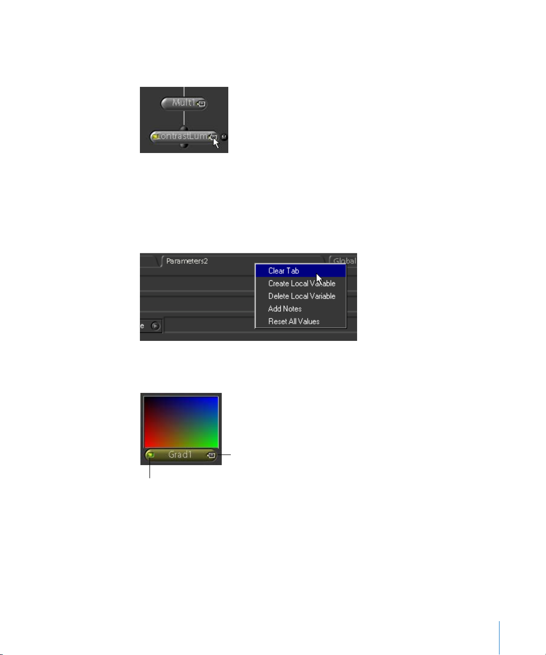
The parameters indicator appears on the right side of the node, and the node’s
parameters are loaded into the Parameters2 tab. The node does not have to be
selected in order to load its parameters into the Parameters2 tab.
Loading a node’s parameters into a tab automatically clears out whatever previous
parameters were loaded. If necessary, you can clear a Parameters tab at any time.
To clear a tab so that no parameters are loaded into it:
m
Right-click the Parameters1 or Parameters2 tab, then choose Clear Tab from the
shortcut menu.
It’s important to bear in mind that you can load the image from one node into the
Viewer, while loading another node’s parameters into the Parameters tab.
Click to load node
parameters.
Click once to display node in Viewer.
Double-click to load node parameters.
Chapter 1 An Overview of the Shake User Interface 73
Page 74
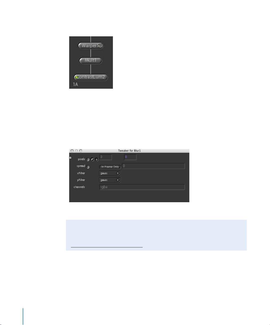
For example, you can view the resulting image from the bottommost node in a tree,
while adjusting the parameters of a node that’s farther up in that tree.
The indicator on the left shows which nodes are loaded into Viewers, and the indicator
on the right shows which nodes have been loaded into one of the Parameters tabs.
Using Tweaker Windows
You can also open a node’s parameters in a floating “Tweaker” window.
To open a Tweaker window:
m
Select a node and press Control-T.
The Tweaker window appears, floating above the Shake window.
Global Parameters
You can double-click an empty area in the Node View to open the Globals tab, or click
the Globals tab itself. For more information on the global parameters, see Chapter 2,
“Setting a Script’s Global Parameters,” on page 91.
Adjusting Parameter Controls
The Shake interface incorporates a variety of parameter controls. Many parameters
found in the Parameters tab and Globals tab have subparameters. A plus sign (+)
beside a parameter indicates that there are related subparameters. Click the plus sign
to open the parameter subtree and access the subparameters.
74 Chapter 1 An Overview of the Shake User Interface
Page 75
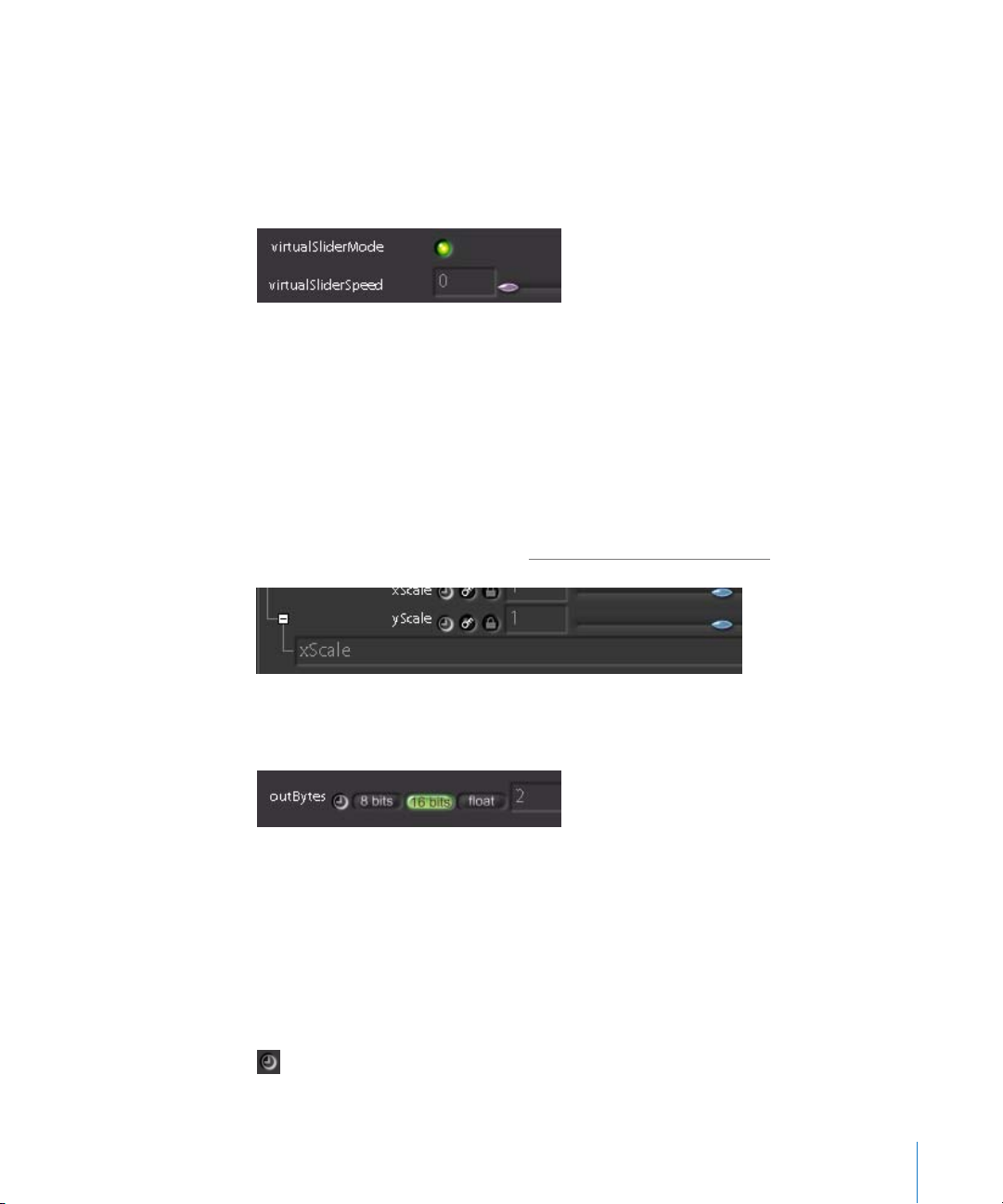
Each parameter has several types of controls that you can use to change that
parameter’s numerical value.
• Sliders: Move the slider (if available) to modify the parameter’s value.
• Virtual sliders: These sliders—controlled by dragging in a value field—allow you to
increase or decrease a parameter’s value beyond the limits of a standard slider. Drag
left or right in a value field to decrease or increase a parameter’s numeric value.
Note: If you are using a Wacom tablet, open to the Globals tab, open the guiControls
subtree, enable virtualSliderMode, then set virtualSliderSpeed to 0.
When a parameter has an expression attached to it, a plus sign (+) appears beside the
parameter name. (The plus sign is also used to indicate a parameter that has hidden
subparameters.) An expression can be an animation curve, a link to a different
parameter, or a function. Clicking the plus sign beside a parameter that’s linked to an
expression reveals the expression field. To clear a non-curve expression, move the
slider, enter a new value in the value field, or right-click and select Clear Expression. For
an introduction to expressions, see “U
sing Expressions in Parameters” on page 78.
• Some parameters have associated toggle buttons. You can enter a value in the value
field, or click the toggle button. You can also enter expressions in the value field.
• Press Tab or Shift-Tab to advance or retreat into adjacent value fields.
Keyframing and Curve Editor Controls
Two controls let you load a parameter into the Curve Editor, and enable it to be
animated using keyframes.
The Load Curves button (the clock-shaped button to the immediate right of a
parameter name) loads parameters into the Curve Editor.
Chapter 1 An Overview of the Shake User Interface 75
Page 76

When the Load Curves button is enabled (checked), the parameter is displayed in the
Curve Editor. When disabled, the parameter does not appear in the Curve Editor.
The Autokey button enables keyframing for that parameter.
For more information on animating parameters, see Chapter 10, “P
arameter Animation
and the Curve Editor,” on page 291.
Locking a Parameter
Most parameters have a lock button next to the Autokey button. This control lets you
lock that parameter so that it can’t be modified.
When you lock a parameter, its value field turns red to indicate that it’s locked.
Locked parameters cannot be edited, but if they contain keyframes, an expression, or a
link to another parameter, these values continue to animate that parameter.
Using Color Controls
Some parameters have associated Color controls.
To use a Color control, do one of the following:
m
Click the Color control (the color swatch)—the Color Picker opens, and you select your
color from the Color Picker or Viewer.
76 Chapter 1 An Overview of the Shake User Interface
Page 77
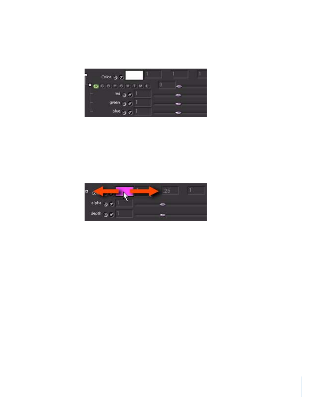
m
Click the plus (+) sign to the left of the Color control to access color subparameters. The
first row in the subtree contains a slider to modify one channel at a time. Select the
button that corresponds to the desired channel: (R)ed, (G)reen, (B)lue, (O)ffset, (H)ue,
(S)aturation, (V)alue, (T)emperature, (M)agenta-Cyan, or (L)uminance. Move the slider
to calculate according to the selected channel, but convert the numbers back to RGB.
m
Edit the individual channels or add expressions in the subtree.
m
You can also keep the subtree closed, and use the Color control (the color swatch) itself
as a virtual slider. Using the channel buttons as the keyboard guide, press and hold the
desired key (R, G, B, H, S, V, and so on) and drag left or right in the Color control. In the
following illustration, when G is pressed and the pointer is dragged, the green channel
increases or decreases.
Note: To adjust the red, green, and blue color channels at the same time, press O and
drag in the Color control (O represents Offset).
Using Pop-Up Menus
Some parameters have associated pop-up menus, such as the font parameter in the
Tex t node.
There are two ways to choose items from a pop-up menu:
m
Click a menu item to choose that item, then close the menu.
m
Right-click a menu item to choose it and remain in the menu. When you first click the
menu item, hold down the left mouse button and move the pointer off of the menu.
Then return the pointer to the menu and right-click. This allows you to quickly test
different parameters.
Chapter 1 An Overview of the Shake User Interface 77
Page 78
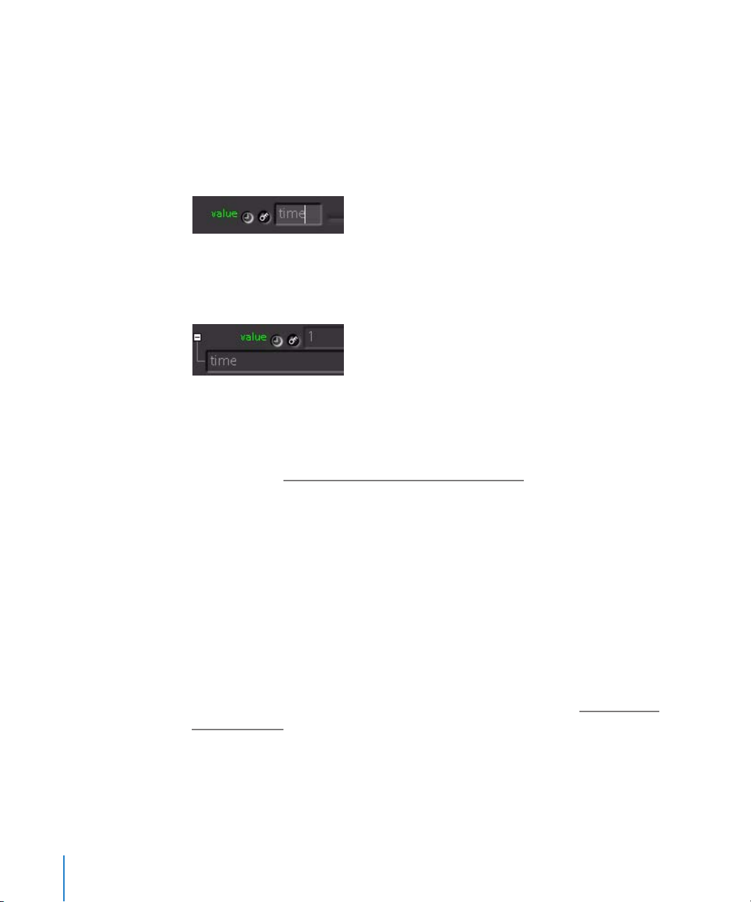
Using Expressions in Parameters
An expression is any non-numeric entry, such as a variable or a mathematical
calculation. Any parameter can use an expression. Some expressions, such as time, are
extremely simple. When you type the expression variable “time” into a value field,
Shake returns the numeric value of the current playhead position. For example, if the
playhead (in the Time Bar) is parked at frame 1, typing “time” into a value field returns a
value of 1 in that field.
Entering an expression consisting of any letter (whether valid or not) activates a plus
sign (+) to the left of the parameter name. To edit a parameter’s expression, click the
plus sign to open an expression field underneath.
If the parameter has an expression and you make an adjustment to that parameter’s
slider, the expression is removed in favor of your numerical change. If the parameter is
animated, however, these special expressions are recognized by Shake and are not
removed when the slider is adjusted. For more information on animating parameters,
see Chapter 10, “P
arameter Animation and the Curve Editor,” on page 291.
Note: You can also remove an expression by right-clicking the field and selecting Clear
Expression from the shortcut menu.
You can modify expressions in various ways:
• To load or save an expression, use the right-click menu.
• To create extra sliders to build complex expressions (and still allow interactive input),
right-click the field and select Create Local Variable. To remove a local variable, rightclick and select Delete Local Variable.
For a lesson on using local variables and expressions, see Tutorial 4, “Working With
Expressions,” in the Shake 4 Tutorials.
For a list of mathematical expressions and variables, see Chapter 30, “Installing and
Creating Macros,” on page 905.
78 Chapter 1 An Overview of the Shake User Interface
Page 79

Linking One Parameter to Another
You can link any parameter to any other parameter.
To link parameter A to parameter B within the same node:
m
Enter the name of parameter A into the value field of parameter B, then press Return. A
plus sign appears to indicate that the parameter now contains an expression.
For example, in a Move2D node, you would link yPan to xPan by typing the following
into the yPan parameter:
xPan
Note: The default state of many parameters is an expression which links them to an
accompanying parameter. This is most common for pairs of parameters that define X
and Y values. For example, the default argument for yScale is a link to xScale.
To link to a parameter in a different node, preface the link with the following syntax:
nodeName.parameter
For example, to link the red channel parameter of the Add1 node to the red channel
parameter of the Add2 node, enter the following expression in the Add1 red channel:
Add2.red
To interactively copy a parameter from one field to another in the same node,
do one of the following:
m
Click the parameter name you want to copy, and drag it to the parameter name (a
value or expression) that you want to copy the value to. This copies the value from the
first field to the second.
Note: This drag and drop behavior also works when you drag color from one Color
control to another.
m
Select text in a value field and press Command-C or Control-C to copy the information.
Go to the second value field and press Command-V or Control-V to paste.
m
To interactively link two parameters together, Shift-drag a parameter name and drop it
onto the parameter you want to link to. This creates an expression linking back to the
first parameter by listing its name.
Combining Links With Expressions
Parameter links can be used in conjunction with mathematical expressions as well. For
example, to double the value of a link, enter:
Add2.red*2
To link to a parameter at a different frame than the current one, use the @@ signs. For
example, to link to Mult1’s red parameter from two frames earlier, use the following
expression:
Mult1.red@@(time-2)
Chapter 1 An Overview of the Shake User Interface 79
Page 80

Displaying Parameter Values in the Viewer
You can dynamically display the values of parameters using the Te xt and AddText nodes.
To differentiate a parameter name from regular text in the value field, surround it with
a pair of braces. For example:
The current frame is: {time}
displays the following in the Viewer:
The current frame is: x
where x automatically updates as each frame progresses.
In another example, if there is a node called Gamma1, and its rGamma value is 1.7,
entering the following expression into the text parameter of a Text node:
My red value = {Gamma1.rGamma}
displays the following in the Viewer:
My red value is 1.7
Note: There is a macro called Wedge in the “Cookbook” section of this manual that can
be used to print out wedging values for color timing Cineon files.
For a lesson on linking parameters, see Tutorial 4, “Working With Expressions,” in the
Shake 4 Tutorials.
Copying and Pasting Script Code in Shake
If you copy a group of nodes from the node tree, open a text editor, and paste the
result, you’ll see the actual code that Shake is using to perform the operations those
nodes represent. The following screenshots show a simple composite in the Shake
interface, and those same three nodes copied and pasted into a text editor.
At times, various script code and expressions are featured in the Shake documentation.
Many times, examples and expressions you see presented in a coded format can be
copied from the onscreen documentation and pasted into Shake, for immediate use.
80 Chapter 1 An Overview of the Shake User Interface
Page 81

The Parameters Tab Shortcut Menu
The following table lists the options that appear when you right-click the top portion
of the Parameters tab.
Option Description
Clear Tab Unloads the current parameters from the tab.
Create Local Variable Allows you to create a variable specific to a given node. Use this
option when you want to link one or more parameters to other
parameters. See Tutorial 4, “Working With Expressions,” in the Shake
4 Tutorials.
Delete Local Variable Deletes the local variable for the selected parameter.
Add Notes A dedicated local variable in string format. Allows you to add notes
to any node (to help you remember what you were thinking at the
time).
Reset All Values Resets all values in the node to their default state.
The following table lists the options that are available when you right-click a parameter.
Option Keyboard Description
Copy Command-C or
Control-C
Paste Command-V or
Control-V
Load
Expression
Save
Expression
Clear
Expression
Clear Tab Clears the current parameters from the tab.
Create Local
Variable
Delete Local
Variable
Add Notes A dedicated local variable in string format. Allows you to add notes
Copies the selected nodes onto the Clipboard.
Pastes the Clipboard contents into the Node View. You can also
copy nodes from the Node View and paste the nodes into a text
document, and copy the text and paste it into the Node View.
Loads an expression from disk. The expression should be in Shake
format. You can use this if you have a translator for another
package’s curve types.
Saves the current expression as a text file to disk.
Clears the current expression.
Allows you to create a variable specific to that node. Use this when
you want to drive one or more parameters off of other parameters.
See Tutorial 4, “Working With Expressions,” in the Shake 4 Tutorials.
Deletes the local variable for the selected parameter.
to any node.
Chapter 1 An Overview of the Shake User Interface 81
Page 82

The Domain of Definition (DOD)
The Domain of Definition (DOD) is a rectangular zone that Shake uses to bind the
significant pixels in an image in order to optimize rendering speed. Everything outside
of the DOD is considered as background (black by default), and is therefore ignored in
most computations. Proper handling of the DOD is an extremely powerful way to
speed your render times.
To examine the efficiency of the DOD node:
1 Create an Image–Tex t node.
2 Ensure that the Display DOD button in the Viewer is on.
The green box that you see around the text in the Viewer is the DOD.
Because of the DOD, nodes attached to this image process in a fraction of the time it
takes to calculate the same nodes with an image that fills the frame.
To test rendering times with DOD:
1 Attach a Filter–RBlur node to the Text node, and set the RBlur oRadius parameter to 360.
2 In a separate branch, create an Image–Rand node (to create an entire frame of pixels).
3 Attach a Color–Monochrome node to the Rand node to turn it into a two-channel
image. The Text node creates a BWA (black and white, with alpha) image by default, so
you must match the channels to compare rendering speeds.
4 Copy and paste the RBlur1 node into the Node View, then attach the copied node
(RBlur2) to the Monochrome1 node.
82 Chapter 1 An Overview of the Shake User Interface
Page 83

There is a significant difference in rendering speed, even though both images are the
same resolution.
Assigning a DOD
All images from disk are automatically assigned a DOD that is equal to the resolution of
the image. There are five ways to alter the DOD:
• Images generated in Shake have a DOD. For example, nodes from the Image tab such
as RGrad, Tex t, and RotoShape automatically have an assigned DOD.
• The DOD of an image from disk that is transformed or filtered is automatically
recalculated. For example, the following image is read in (imported) and scaled down
and/or rotated with a Move2D.
Also, if an image is blurred, the DOD expands accordingly.
• A rendered .iff file from Shake is embedded with a DOD. When Shake writes an .iff
file, it automatically saves the DOD information. Only the .iff format embeds the DOD.
In the following example, the image that was written out in the previous (above)
example is read back into Shake.
Chapter 1 An Overview of the Shake User Interface 83
Page 84

• The SetDOD node, located in the Transform tab, allows you to manually assign a DOD
to an image. In the following illustration, a SetDOD node is attached to the building
image to limit the effects to the tower.
• You can combine multiple images using a DOD. When you combine two images, the
DODs combine to form a larger rectangle. If, however, you use a node like Inside or
IMult, that node takes the DOD of the second node. If the building image is placed
Inside of the QuickShape image from above, it inherits the DOD of the QuickShape
node.
Note: When using onscreen controls to edit a shape (for example, a Rotoshape or
QuickPaint object) that has control points within the boundaries of the DOD, move the
pointer over the shape inside of the DOD, and then drag to select the points.
84 Chapter 1 An Overview of the Shake User Interface
Page 85

Combining images with a DOD is an excellent way to optimize greenscreen or
bluescreen images that need to be cropped via a garbage matte anyway, because it
simultaneously removes the garbage areas and assigns an efficient DOD to the image.
The node tree above produces the folowing effect:
Building QuickShape1
Primatte1 Inside1
With a good understanding of the role of the DOD, you can optimize the tree before
and after the node in question. The above example not only optimizes any nodes you
attach to Inside1, but executes the Primatte and reads in the part of the image that is
inside of the DOD, reducing processing and I/O activity.
Keying, Color Correcting, and the Background Color
This section discusses the area outside of the DOD, which is called the Background
Color (BGColor).
Chapter 1 An Overview of the Shake User Interface 85
Page 86

The two main keyers in Shake, Keylight and Primatte, recognize the background color,
and have a toggle to key the background color in or out. By default, the keyer leaves
the background area black in the alpha channel. To turn the background completely
white, toggle BGColor on.
Shake processes color correction of the BGColor very quickly, as it recognizes there is a
pure correction applied to previously black pixels. If the color correction does not
change black, such as Gamma or Mult, it is ignored. If it does affect the black areas, as
does Add or Compress, it processes these areas, but understands that they are still the
result of a lookup process. Therefore, the DOD does not get reasserted to the resolution
frame. This is the same process that is used when the Infinite Workspace kicks in. So,
even though the pixels outside of the DOD are not visibly different from the pixels
inside, the DOD remains in place. (For more information, see Chapter 7, “U
sing the Node
View,” on page 217.)
86 Chapter 1 An Overview of the Shake User Interface
Page 87

There may be cases, however, where you want to take advantage of the DOD for
masking purposes. In this tree, an image is scaled down, and the brightness increased
with an Add node. This, however, turns the area outside of the image a medium gray.
Since this area is recognized as outside of the DOD, it can be returned to black with a
Color–SetBGColor node, which sets the color for the area outside of the DOD.
Building Move2D1
Add1 SetBGColor1
The Layer–Constraint node also limits a process. For more information on masking
using the Constraint node, see Chapter 19, “U
Chapter 1 An Overview of the Shake User Interface 87
sing Masks,” on page 527.
Page 88

The Time Bar
The Time Bar, at the bottom of the Shake window, displays the currently defined range
of frames, the playback buttons, and the Info field, which provides a brief description of
each control you move the pointer over.
The Time Bar is a display of the currently defined time range. It neither limits nor
controls the actual parameters that are saved into the script. To set the frame range
that renders via a FileOut or Flipbook operation, go to the Globals tab and enter the
frame range in the timeRange parameter.
Setting a Script’s Frame Range
The number in the field to the left of the bar is the start frame of the Time Bar, and the
number in the field to the right is the end frame. In the above example, frames 1 to 21
are highlighted. This corresponds to an entry in the timeRange parameter of the
globals of 1-21.
Time Bar Navigation Values
The Current Frame field indicates the position of the playhead, which is 49. The
Increment parameter controls how far the playhead advances when you press the Left
Arrow or Right Arrow key.
• The default value of 1 means that every frame is played back.
• A default value of 0.5 enables you to see each field when a video clip is loaded into
the Viewer.
• A value of 2 or higher means that Shake skips frames. At 2, every other frame is
skipped.
When you move the pointer within the Time Bar, the frame number that you’ll jump to
when you click to reposition the playhead is displayed over the pointer.
If you have already set the timeRange parameter in the Globals tab, click Home in the
Time Bar controls to use the timeRange as the Time Bar frame range.
To change the current time and display that frame in the Viewer, do one of the
following:
m
Click or drag the playhead to interactively scrub across the current time range.
m
To jump to a specific frame, type the frame number into the Current Frame field, and
press Return. As with any value field, you can use the virtual sliders—press Control and
drag the pointer left and right in the value field.
88 Chapter 1 An Overview of the Shake User Interface
Page 89

m
To pan across the Time Bar, press the middle mouse button and drag; or Option-click or
Alt-click and drag.
m
To zoom into or out of the frame range displayed by the Time Bar, press Control and
the middle mouse button; or Control-Option-click or Control-Alt-click, then drag.
Playback Controls
The controls illustrated below play through the script according to the Time Bar frame
range, not the global timeRange.
• To play forward, click the forward arrow button.
• To play backward, click the backward arrow button.
Note: Regardless of the speed of your computer, Viewer playback is now limited to
the frame rate specified in the framesPerSecond parameter in the Format section of
the Globals tab.
Assuming your composition is cached so that real-time playback is possible, this
playback rate is not exact, but may vary by around 10 percent.
• To stop playback, click the stop button, or click the left mouse button anywhere on
the screen.
• Shift-click a playback button to render all frames in the current frame range and store
the frames in memory. The sequence will play back much faster next time.
• Click the keyframe buttons to jump to the previous or next keyframe.
The following table lists additional keyboard shortcuts.
Keyboard Description
Left Arrow key or Right Arrow
key
Up Arrow key or Down Arrow
key
.Play forward.
Shift-. Begin cached playback.
Home Fit the current time range into the Time Bar.
TToggle timecode/frame display.
For more information, see Chapter 8, “U
Chapter 1 An Overview of the Shake User Interface 89
Retreat/advance a frame based on the frame Increment setting
(works in any window).
Jump to next/previous keyframe.
sing the Time View,” on page 261.
Page 90
Previewing Your Script Using the Flipbook
You can render a temporary Flipbook to preview your work. Once the Flipbook has
rendered into RAM, use the playback buttons (described below) to play back the
Flipbook. The Flipbook is available on Mac OS X and Linux systems.
To launch the Flipbook from the interface:
1 In the Globals tab, set the timeRange, for example, 1-50 or1-50x2.
2 Load the node that contains the image you want to preview into the main Viewer.
3 Click the Flipbook button in the Viewer shelf.
A Flipbook window appears, and the specified timeRange is rendered into RAM for
playback.
4 When the render is finished, press the period or > key to play the result. When you’re
finished viewing the Flipbook, close the window and it disappears from memory.
On a Mac OS X system, you also have the option to create a disk-based QuickTime
Flipbook. For more information on using both RAM and disk-based Flipbooks, see
Chapter 11, “T
he Flipbook, Monitor Previews, and Color Calibration,” on page 323.
90 Chapter 1 An Overview of the Shake User Interface
Page 91

2 Setting a Script’s Global
Parameters
2
This chapter covers how to set the global parameters
within each script, tailoring your script’s properties to fit
your needs.
About Global Parameters
When you create a new script, you should customize its global parameters before
starting work on your composite. The Globals tab contains parameters that are
commonly found in the Project Properties window of other applications. These
parameters include a script’s time range, default frame width and height, aspect ratio,
proxy settings, global motion-blur controls, bit depth, field rendering settings, and
various ways to customize Shake’s controls.
The global parameters also contain a group of guiControl parameters that let you
customize how Shake works. Using the guiControl parameters, you can specify whether
thumbnails are exposed, how many threads Shake uses on multi-processing
computers, the colors used by shapes and noodles, and the sensitivity of shape
controls in the Viewer.
Setting Global Variables From the Command Line
Many of the parameters described in this chapter can be set in the command line at
the time you launch Shake, so you don’t have to reset them each time you write out a
script. For example, your timeRange may be 1-10, but you can modify that when you
render on the command line with the -t option:
shake -exec my_script -t 1-240
To access the global parameters, do one of the following:
m
Click the Globals tab.
m
Double-click an empty area in the Node View.
91
Page 92

Note: The global controls also appear in the Parameters1 tab when Shake is first
started, or whenever you create a new script.
The global parameters that can be seen in the Globals tab of the Shake interface are
divided into several groups.
The Main Global Parameters
These parameters control the duration and format of the output from your script. While
these parameters can be changed at any time, it’s a good idea to set them to the
proper values before you begin any serious compositing.
timeRange
This parameter defines the number of frames in your project. This parameter can be
changed at any time. The timeRange is generally represented by a starting value and
an ending value, separated by a dash. For example, a 10-second clip in a project that’s
set to a frame rate of 24 fps would have a timeRange parameter set to “1-240.”
The fastest way to set the timeRange is to open the Globals tab and click Auto, which is
located to the right of the timeRange field.
Clicking Auto automatically populates the timeRange parameter by calculating the
duration from the earliest frame in any FileIn node to the last frame in any FileIn node.
92 Chapter 2 Setting a Script’s Global Parameters
Page 93

The starting frame does not always have to be set to 1. For example, to quickly trim off
the first 20 frames of your project, change the timeRange to “21-240.” Doing this
restricts the frame range displayed in the Time Bar and the processing and rendering of
your script to only the frames you need.
Here are some more examples of frame ranges you can define in Shake.
Time Range Number of Frames Frames Rendered
1-100 100 1, 2, 3... 100
1-100x2 50 1, 3, 5... 99
1-100x20 5 1, 21, 41... 81
1-20, 30-40 31 1, 2, 3... 20, and 30, 31, 32... 40
1-10x2, 15, 18, 20-25 13 1, 3, 5... 9, 15, 18, 20, 21, 22 ... 25
100-1 100 100, 99, 98... 2
Several parameters and controls in Shake either inherit the timeRange parameter
directly, or allow you to assign its value:
• The Home button in the playback controls
• The Render Parameters window
• The Time Range parameter in the Mixdown Options of the Audio Panel
• The Flipbook Render Parameters window
useProxy
A proxy is a lower-resolution image that can be temporarily substituted for the highresolution plates in your script, allowing you to work and see rendered tests faster.
Because the images are smaller, you drastically decrease the processing time, memory
requirements, and the amount of time spent on reading and writing files as you work.
Naturally, the trade-off is that the quality of the image displayed in the Viewer suffers as
well, which is why proxies are generally used only when creating low-resolution comps
or creating test previews. After assembling a script using proxies, you can return your
script to the original, full resolution in order to render the final output.
These controls are linked to the proxy buttons found at the upper-right corner of the
Shake interface, and allow you to switch among different resolutions to reap the
aforementioned benefits. For more information on using proxies, see Chapter 4, “U
sing
Proxies,” on page 137.
Chapter 2 Setting a Script’s Global Parameters 93
Page 94

interactiveScale
If the general processing speed for your operations is fine, but the interactivity of
processor-intensive operations is slowing you down, you can turn on the
InteractiveScale option in the Globals tab to use a proxy resolution only while you’re
adjusting parameters. This option does not affect your Flipbooks or FileOut renders. For
more information, see “U
sing interactiveScale” on page 139.
motionBlur
In Shake, motion blur can be applied to animated transformation parameters. Each
transform node has its own motion blur settings, so you can tune each one individually.
The motionBlur parameters in the Globals tab either adjust or replace the existing
values within each node in the script, depending on the parameter. You can also set
the global motionBlur value to 0 to turn all motion blur within your project off. For
more information on using motion blur, see “C
reating Motion Blur in Shake” on
page 778.
The Format Pop-Up Menu
The format pop-up menu provides a fast way of simultaneously setting all the format
subparameters found within the format parameter subtree. The format pop-up menu
contains many of the most popular media formats.
default
Name
Academy 1828 1332 1 1 24
CinemaScope 1828 1556 .5 2 24
Full 2048 1556 1 1 24
1. 8 5 1 828 1332 1 1 24
HDTV1080i/p
30FPS
HDTV1080i/p
29.97 FPS ND
HDTV1080i/p
29.97 FPS DF
HDTV1080i/p
25 FPS
HDTV1080i/p
24 FPS
HDTV1080i/p
23.98 FPS
NTSC ND (D1 4:3) 720 486 1.1111 .9 29.97
NTSC DF (D1 4:3) 720 486 1.1111 .9 29.97
NTSC ND (16:9) 720 486 .83333 1.2 29.97
NTSC DF (16:9) 720 486 .83333 1.2 29.97
Width
192 0 1080 1 1 30
192 0 1080 1 1 29.97
192 0 1080 1 1 29.97
192 0 1080 1 1 25
192 0 1080 1 1 24
192 0 1080 1 1 23.98
default
Height
default
Aspect
default
ViewerAspect
framesPerSecond
94 Chapter 2 Setting a Script’s Global Parameters
Page 95

default
Name
PAL (D1 4:3) 720 576 .9380 1.066 25
PAL (16:9) 720 576 .7032 1.422 25
PAL (square) 768 576 1 1 25
Width
default
Height
default
Aspect
default
ViewerAspect
framesPerSecond
If the format you need is not in this list, you can always open up the format parameter
subtree—by clicking the “+” (plus) icon to the left of the parameter name—and create
your own custom format.
These settings are only for Shake-generated image nodes—they have no effect on the
resolution or frame rate of media referenced by FileIn nodes. Shake generated nodes,
such as RotoShape, QuickPaint, Ramp, and Grad inherit the global resolution.
Click the “+” (plus) icon to reveal the format parameter subtree, which contains the
following subparameters:
framesPerSecond
This parameter limits the speed of playback from the Time Bar, and also sets the default
playback rate of launched Flipbooks. Three buttons provide the three most common
frame rates, Film at 24 fps, NTSC video at 29.97 fps, and PAL video at 25 fps. A value
field allows you to enter a custom frame rate to accommodate any other format.
Note: To change the playback rate within the Flipbook, press + and – (on the numeric
keypad). The current frame rate is displayed at the top of the Flipbook.
timecodeMode
Sets how timecode is calculated within your script, as 24 fps, 25 fps, 30 fps drop frame,
or 30 fps non-drop frame. This parameter is unrelated to timecode that might be
present in a QuickTime movie.
Note: Shake does not import timecode associated with QuickTime movies.
defaultWidth, defaultHeight
The width and height of the frame for Shake-generated images. See the above table for
standard frame sizes.
defaultAspect
The pixel aspect ratio used for Shake-generated images. This should be set to match
the format of the images you’re reading into your script. For example, since most
standard-definition video formats have nonsquare pixels, the aspect ratio of NTSC
video is 1.111, while that of PAL video is .9380. Academy ratio film, which has square
pixels, is simply 1. For more information on pixel aspect ratios, see “A
bout Aspect Ratios
and Nonsquare Pixels” on page 209.
Chapter 2 Setting a Script’s Global Parameters 95
Page 96

defaultViewerAspectRatio
This value corrects the aspect ratio of the image displayed by the Viewer to account for
images using nonsquare pixels. The defaultViewerAspectRatio parameter is for display
only, and has no effect on rendered output.
Changing any format subparameter sets the format pop-up menu to Custom. If there’s
a particular custom format that you use frequently, you can add it to the Format popup list. For more information on adding entries to the format pop-up menu, see
ustomizing the Format Pop-Up Menu” on page 96.
“C
defaultBytes
Sets the default bit rate for Shake-generated images. The defaultBytes parameter has
no effect on images that are read in via FileIn nodes, nor does it affect the rendered
output from your script.
viewerZoom
The zoom level applied to the Viewer. This value has no effect on the output resolution
of your script.
viewerAspectRatio
When set to formatDefault, this parameter scales the X axis of the Viewer by the
defaultViewerAspectRatio parameter, located within the format subtree. When this
parameter is set to custom, you can change it to whatever value you want. This is
usually used to compensate for the nonsquare pixel ratios of video. For anamorphic
film frames, you typically use the proxyRatio to scale down the Viewer’s Y axis.
Customizing the Format Pop-Up Menu
You can create your own formats in a startup.h file. In $HOME/nreal/include/startup,
add a line in the following format:
DefFormatType(“Name”, defaultWidth, defaultHeight, defaultAspect,
defaultViewerAspectRatio, framesPerSecond, fieldRendering)
For example:
DefFormatType(“NTSC (D1 4:3)”, 720, 486, 1/.9f, 0.9f, 29.97,0);
renderControls
These parameters affect how Shake renders material processed by the currently open
script.
fieldRendering
When fieldRendering is set to 0, progressive scan/full frames are rendered. When set to
1, the odd field takes precedence, meaning it is the first line at the top. For more
information on setting up your script to render fields properly, see “T
Processing Interlaced Video” on page 191.
96 Chapter 2 Setting a Script’s Global Parameters
he Basics of
Page 97

quality
When this parameter is set to lo (0), anti-aliasing is disabled. This results in poorer
image quality, but improved render speed.
maxThread
Set the maxThread to the number of available processors you want to use for rendering
by Shake.
cacheMode
The cache is a directory or precalculated images with script information attached.
When Shake evaluates a node tree at a given frame, it compares the tree to the cache
to see if it has rendered that frame before. If it has, it calls up the cached image rather
than recalculate the entire tree in order to save time. Shake keeps track of how many
times each cached frame has been viewed, eliminating the least viewed frames first
when the cache runs out of room.
You can set the cacheMode to one of four states:
• none: Cache data is neither read from nor written to.
• read-only: Preexisting cache data is read, but no new cache data is generated.
• regular: The cache is both read from and written to, but only nodes with non-
animated values are cached.
• aggressive: The cache is both read from and written to, and nodes with animated
and non-animated parameters are cached.
When setting the cacheMode, consider the following guidelines:
• In most circumstances, the regular cacheMode setting should be used.
• Consider setting the cacheMode to aggressive when you are constantly scrubbing
back and forth between two or three frames (for example, when tweaking tracking
or shape control points).
• You should only set cacheMode to none if you are using Shake on a system with
extremely limited RAM and disk space. By setting the cacheMode to none, Shake is
forced to re-compute each image that you select to view, which is the least efficient
way to run.
For more information on Shake’s caching system, see Chapter 13, “Image C
aching,” on
page 343.
macroCheck
If you open or load a script on your system, and the script does not appear, the script
may contain macros that are not on your system. If this is the problem, a message
similar to the following appears in the Console tab:
line 43: unknown function MissingMacro
MissingMacro1=MissingMacro(Keylight_1v41);
Chapter 2 Setting a Script’s Global Parameters 97
Page 98

To open or load a script that contains a missing macro:
1 Click the Globals tab.
2 Expand the renderControls subtree.
3 Set macroCheck to one of the following options:
• abort load: does not load the script
• sub. with text: substitutes a Tex t node in place of the missing macro
• sub. no text: substitutes a MissingMacro node
4 Open/load the script.
To set the default macroCheck behavior to substitute a MissingMacro node, include the
following in a .h file:
sys.useAltOnMissingFunc = 2
For more information on .h files, see “Creating and Saving .h Preference Files” on
page 355.
guiControls
The parameters within the guiControls subtree allow you to customize the functionality
and display of controls in Shake’s graphical user interface. These settings are
individually saved by each script you create.
displayThumbnails
Turns all thumbnails in the Node View on and off. For more information on customizing
the thumbnail display, see “C
ustomizing Thumbnail Display” on page 253.
displayThumbnails has three subparameters—thumbSizeRelative, thumbSize, and
thumbAlphaBlend.
thumbSizeRelative
Scales all thumbnails to the same size, or leaves them at different sizes relative to the
original sizes of the images. By default, all thumbnails are displayed at the same width.
To display thumbnails at their relative sizes, turn on thumbSizeRelative.
thumbSize
Lets you adjust the size of thumbnails in the Node View. If thumbSizeRelative is turned
on, all nodes are resized relative to one another.
thumbAlphaBlend
Turns thumbnail transparency on and off. When thumbAlphaBlend is on, moving one
thumbnail over another results in a fast look at how the nodes might appear when
composited together in the Viewer. More usefully, it gives you an instant view of which
images have transparency in them.
98 Chapter 2 Setting a Script’s Global Parameters
Page 99

virtualSliderMode
When this parameter is turned off, dragging within any parameter’s value field in Shake
results in an edit bar appearing and the contents of that field being selected. When this
parameter is turned on, dragging within a parameter’s value field results in that
parameter being modified as if you were dragging a slider. This mode is very useful
when using Shake with a graphics tablet. You can also use these virtual sliders in the
value fields simply by dragging with the mouse.
virtualSliderSpeed
Adjusts the speed of the virtual slider. When using a stylus, it is recommended you set
this parameter to 0.
noodleTension
Lets you adjust how much “slack” there is in the way noodles are drawn from knot to
knot. Higher values introduce more slack, and noodles are more curved. Lower values
reduce the slack, and noodles are drawn in more of a straight line.
shapeControls
These subparameters allow you to customize the spline-based shape drawing and
editing behaviors and transform controls in the Viewer. You can change these
parameters to make it easier to use Shake’s controls for your individual needs.
rotoAutoControlScale
An option which, when enabled, increases the size of the transform controls of shapes
based on the vertical resolution of the image to which the shape is assigned. This
makes it easier to manipulate a shape’s transform control even when the image is
scaled down by a large ratio.
rotoControlScale
A slider which allows you to change the default size of all transform controls in the
Viewer when rotoAutoControlScale is turned on.
Note: You can also resize every transform control appearing in the Viewer by holding
the Command key down while dragging the handles of any transform control in the
Viewer.
rotoTransformIncrement
This parameter allows you to adjust the sensitivity of shape transform controls. When
this parameter is set to lower values, transform handles move more slowly when
dragged, allowing more detailed control. At higher values, transform handles move
more quickly when dragged. A slider lets you choose from a range of 1-6. The default
value is 5, which matches the transform control sensitivity of previous versions of
Shake.
Chapter 2 Setting a Script’s Global Parameters 99
Page 100

rotoPickRadius
This parameter provides the ability to select individual points on a shape that fall
within a user-definable region around the pointer. This allows you to easily select
points that are near the pointer which may be hard to select by clicking them directly.
A slider allows you to define how far, in pixels, the pointer may be from a point to
select it.
rotoTangentCreationRadius
This parameter lets you define the distance you must drag the pointer when drawing a
shape point to turn it into a Bezier curve. Using this control, you can make it easier to
create curves when drawing shapes of different sizes. For example, you could increase
the distance you must drag, to avoid accidentally creating Bezier curves, or you can
decrease the distance you must drag, to make it easier to create Bezier curves when
drawing short shape segments.
gridWidth, gridHeight
Specifies, in pixels, how wide and tall each rectangle of the grid is. The gridHeight is
locked to the gridWidth by default, although this expression can be changed. This
default is 40 x 40 pixels.
gridEnabled
Lets you control the grid’s effect on the nodes that you create. There are two settings:
on and off. This parameter also toggles the background grid pattern in the Node View if
gridVisible is turned on.
gridVisible
Displays the grid as a graphical background in the Node View. This graph is only
displayed when gridEnabled is turned on.
layoutTightness
This parameter affects the Layout Arrangement commands described in “A
Nodes” on page 244. It lets you specify how closely nodes should be positioned to one
another when they’re newly created, or whenever you use one of the arrangement
commands. This parameter’s default is 40 pixels.
consoleLineLength
The maximum line length of information displayed in the Console tab. This defaults to
12 0 characters.
100 Chapter 2 Setting a Script’s Global Parameters
rranging
 Loading...