


9116

Introduction 2
Emergency Service Feature 2
Unpacking your phone 2
Key Descriptions 3
Basic Installation 5
Making and Answering Calls 8
Making a call 8
Answering a Call 8
Using the Hold Key 8
Making a Handsfree call 8
Muting a handsfree call 9
Using Redial 9
Call Waiting ID 9
Changing the display language 10
Setting the date and time 10
Adjusting the Handset and Speaker volume 10
Adjusting the Ringer Volume 10
Adjusting the Display Contrast 11
Set Indicator Light 11
Directory 12
Saving numbers and names to the Directory 12
Entering Names 13
Making a call from the Directory 13
Finding items in the Directory 13
Deleting items from the Directory 14
Callers List
Using the Callers List 15
Finding an item in the Callers List 15
Making a call from the Callers List 15
Editing in the Callers List 15
Memory keys 17
Saving numbers and names into memory keys 17
Viewing memory key contents 17
Labeling the memory keys 18
Making calls from memory keys 18
Deleting memory keys 18
Saving features in memory keys 19
Using feature keys 19
Advanced Features 20
Clear Message Waiting 20
Set Area Code 20
Display Icons and Messages 21
Icons in the Caller List 21
Display messages 21
Troubleshooting 22
15
1
Introduction
Introduction
Congratulations....
This guide contains operating information for your 9116.
The 9116 is an advanced single-line telephone, that offers the following features:
• Handsfree (speakerphone) with mute capabilities
• 80 name and number Callers List
• Personal Directory for 20 name and number
directory
• 15 speed dial positions for frequently called
numbers or feature access codes
• Last number redial
. on the purchase of your 9116 telephone.
Emergency Service Feature
The Model 9116 will provide basic telephone service during a power failure. However, only the dial pad, ringer and handset will function. If on a handset call when a
power failure occurs, the Model 9116 will keep the call. Handsfree calls will not be reestablished during a power interruption.
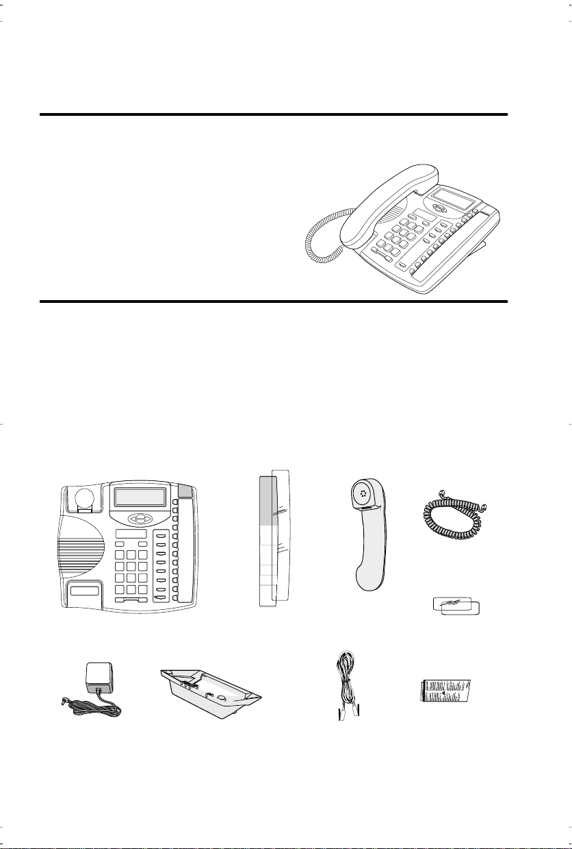
Unpacking your phone
Along with this user guide and the feature card, the following items are included with
your telephone.
Handset cord
Handset
Telephone
Power adaptor
The power adaptor is 9V DC, 300mA - please see the regulatory sheet for safety in structions regarding the power adaptor and operation of the telephone.
Telephone stand
Memory key card
and plastic lens
Telephone line cord
Number card
and plastic lens
Regulatory sheet
2
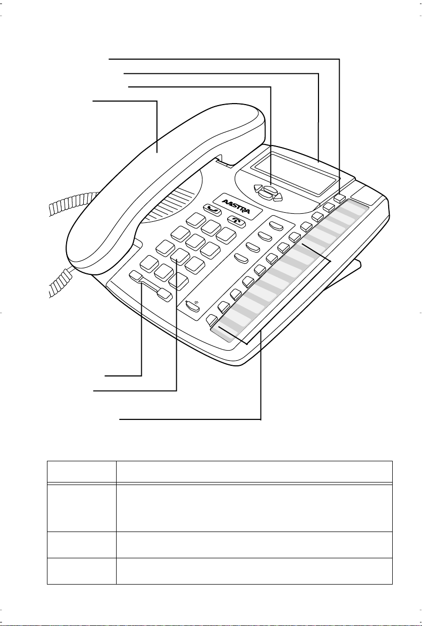
Key Descriptions
Options Key
Movable Display
Navigational Keys
Handset
Introduction
Options
Callers
Flash
Redial
Dial
M
ute
S
Directory
Save
D
elete
h
ift
Volume Bar
Dial Pad
8 Memory Keys
Set Indicator
Light
8 Programmable Keys
I
3
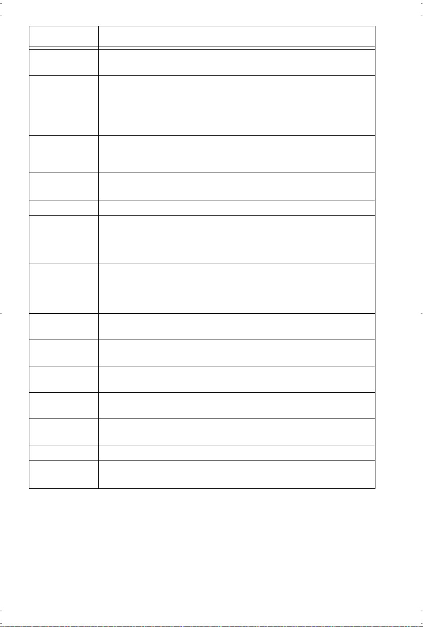
Keys Key Description
Flashes when the telephone rings, or when a call is on hold; lights
up when a message is waiting or when a feature or extension is in
use. See
mation.
Stores a name and number or feature for easy access.
Access a list of 5 options to customize the features of your telephone .
Set indicator light messages
on page 11 for more infor-
Keys Key Description
Introduction
J
S
N
O
R
Q
light indicators
A
B
C
D
K
L
H
M
and
Stores up to 20 names and phone numbers. See
page 12 for more information.
VW
allows you to move up or down in the Directory, Callers
List, Options List and the Redial List. When you are editing entries
on the display, T
numbers U
display or adds a space between characters.
Ends an active call. Goodbye exits an open list, such as the Directory, Options or Callers List. It will not hang up a call that is on
hold.
Places calls on or off hold. See
more information.
Sets the handset and speaker volume while on call.
Activates the speaker and microphone so you can listen and talk
without using the handset; also mutes the microphone so that your
caller cannot hear you (the light indicator will ßash when the
microphone is muted) .
Accesses a list of the last 80 calls received. The list begins with the
newest call and ends with the oldest. The oldest call is automically
deleted to make room for the new calls when the list becomes full.
See
Callers List
Use with the network features such as Call Waiting and Three Way
Calling (ßash is also referred to as link).
Displays the last number dialed out on the telephone. See
Redial
on page 9 for more information.
Dials the displayed telephone number, automatically activates the
handsfree mode if the handset is not picked up.
Use to store numbers and names in Directory, in memory keys and
to access and save Option feature settings.
Removes individual entries in the Directory, or Callers List. Erases
memory key information.
Use to access the eight two-touch memory positions.
Memory keys store numbers, names and features. See
keys
on page 17.
adds a space when entering or editing names or
allows you to view multiple messages on the telephone
Using the Hold Key
on page 15 for more information
Directory
on page 8 for
Memory
on
Using
4
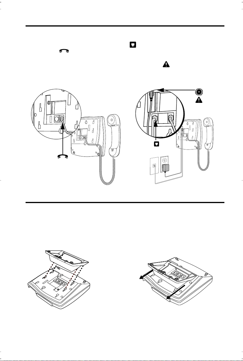
Basic Installation
1. Connect the Handset 2.Connect the Cords
Attach one end of the coiled handset cord
to the handset and the other end to the
handset port on the back of the telephone.
Route the handset cord along the groove
leading off the side of the telephone as
Basic Installation
shown in the illustration.
Plug one end of the telephone cord into
on the back of the telephone and the
other end to the phone jack.
Connect the small end of the power
adaptor to the port on the back of the
telephone, and plug the other end into
an electrical outlet.
1
3. Attach the Stand for Desk Mount
If you plan to mount the telephone on the wall, you do not need to attach the stand.
Lower the stand as shown below into
the slots on the back of the telephone.
Slide the stand in the direction shown
below until it clicks into the locked position.
5
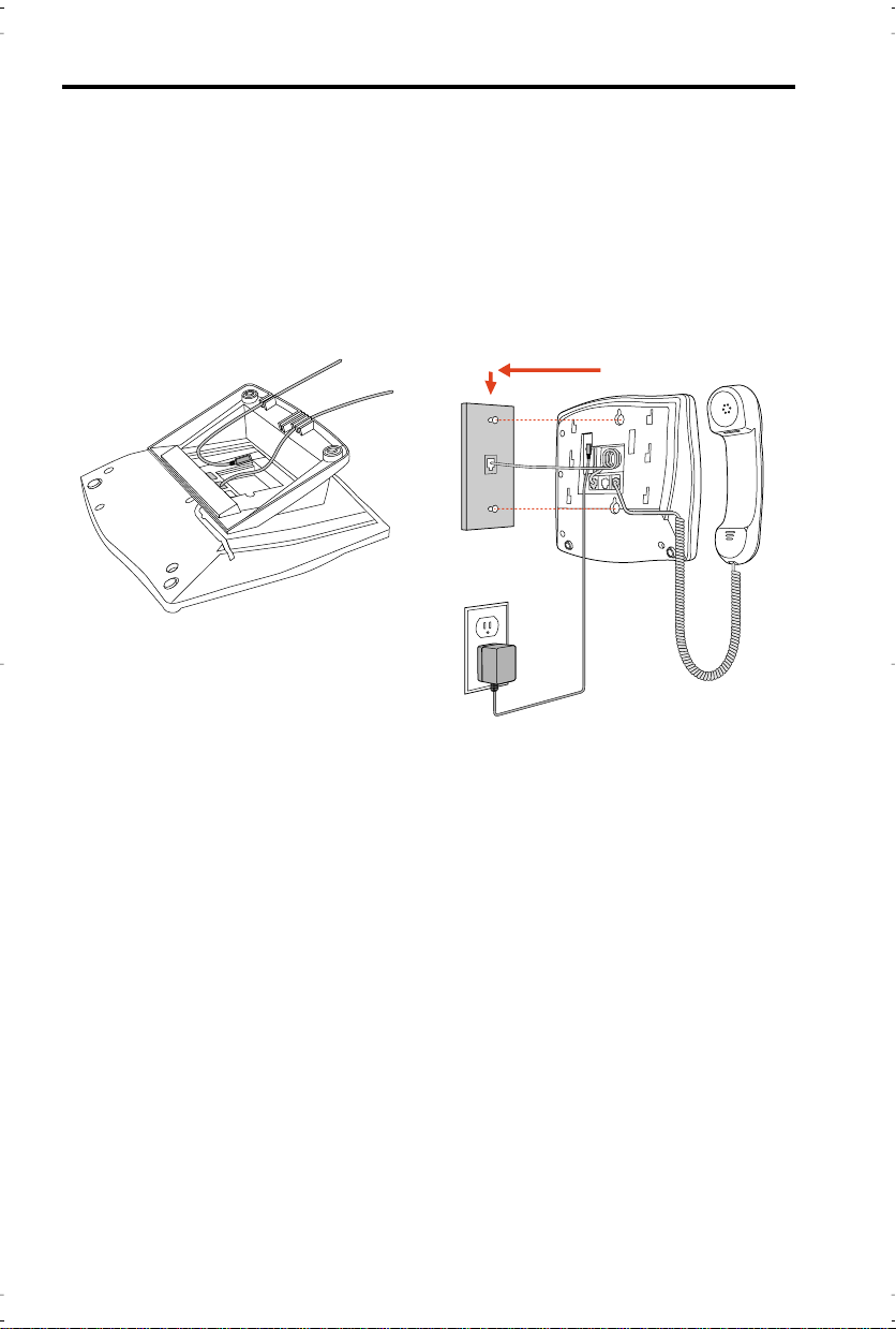
6. Attach the cords to the telephone stand 7. Mount the telephone on the wall
Basic Installation
Route the cords along the groove on the
telephone stand as shown in the illustration.
It is recommended that you use a wallmounting plate which is available
through your telephone company or a
local retailer. You will Þnd it easier to
wall-mount the telephone if you purchase one short 20 cm (8”) telephone
cord and use it in place of the long telephone cord.
Coil the telephone cord(s) into the space
provided on the back of the telephone.
Line up the keys on the wall mounting
plate with the key holes on the back of
the telephone.
Place the telephone onto the wall mounting plate, and then push down to secure
the telephone into place.
6
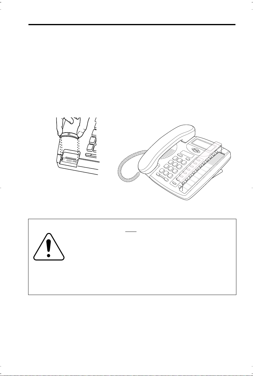
8. Insert the number card on your
telephone
Write your telephone number on
the number card.
Place the number card into the
slot underneath the handset cradle on the on the telephone.
Basic Installation
Gently bend the clear plastic lens
and place it on top of the number
card in the slot.
9. Insert the Memory key card on your telephone
This card contains the feature names for the dedicated keys and label identiÞcation spaces for the
eight programmable memory keys.
Place the card into the memory key card slot on
the telephone.
Gently bend the clear plastic lens and place it on
top of the memory key card in the slot.
For more information on programming memory
keys, refer to
Memory keys
on page 17
To avoid potential electrical shock hazard to personnel or damage
to the telephone, use
and installation procedures. SpeciÞcally, use only 4 conductor
modular teledapt plug/cords with this product, and an AC transformer that is CSA/UL or CSA-NRTL/C approved Class 2 level
C, rated as follows:
For North American Markets AC voltage 110-120V,
60Hz, 10W and Output: 9V DC, 300mA.
Substitution of non-approved equipment will void the Aastra
Telecom Inc., warranty. For more information about installation
and safety concerns, call 1-800-574-1611.
the manufacturer-supplied equipment
only
Input: 120VAC,
7
 Loading...