


Scroll Liquid Chillers
Model CGWF and CCAF 20 to 60 Tons (60 Hz) 17 to 50 Tons (50 Hz)
Water-Cooled and Condenserless
Built For the Industrial and Commercial Markets
January 2004 |
CG-PRC012-EN |
More Than Just Another “Improved”
Chiller
—Advanced Design
—Better Reliability
—Superior Efficiency
—New CH530 Controls
—Better Availability
—Easier To Install and Operate
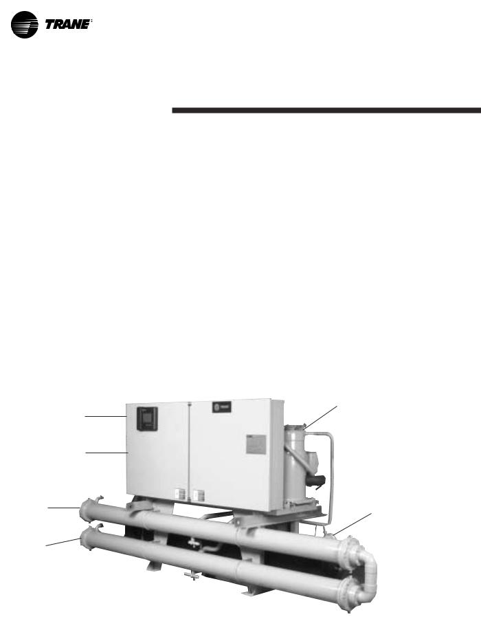
Microprocessor
Operator
Interface
Control
Panel
Condenser
Leaving
Water
Piping
Condenser
Entering
Water
Piping
Introduction
The Trane 20-60 Ton Scroll Liquid Chiller
Design
The Trane scroll compressor is the most advanced scroll compressor in the industry.
Reliability
64 percent fewer compressor parts, compared to reciprocating compressors, mean long and reliable life.
Efficiency
CGWF scroll chillers meet and exceed ASHRAE Standard 90.1 full and part load efficiencies. Part load efficiencies are simply unmatched by reciprocating chillers.
Control
CH530 controls enable scrolling access to inputs and operating information via the LCD touch-screen display. Jobspecific communication options allow greater reporting flexibility. The CH530 is compatable with LonMark communications.
Availability
Fast ship cycles on both stock and built- to-order specials.
Installation
Small unit size, factory wiring, easy lifting provisions, and start-up control logic mean quick and easy setup. Chillers fit through standard singlewidth door.
Operation
Smart safety features and over 60 diagnostic displays mean easy and virtually trouble-free operation.
Rugged
Trane Scroll
Compressor
Evaporator
Leaving
Water Piping
© 2004 American Standard Inc. All rights reserved. |
CG-PRC012-EN |
Contents
Introduction |
2 |
Features and Benefits |
|
4 |
|
World Class Efficiency and Reliability |
|
Options |
|
Controls |
|
8 |
|
Application Considerations |
|
12 |
|
Model Number |
|
13 |
|
General Data |
|
14 |
|
Selection Procedure |
|
15 |
|
Performance Data |
|
16 |
|
Full Load Performance |
|
Part Load Performance |
|
Adjustment Factors |
|
Pressure Drops |
|
Electrical Data and Connections |
|
27 |
|
Typical Wiring Diagram |
|
Field Layout |
|
Dimensional Data |
|
32 |
|
Weights |
|
37 |
|
Mechanical Specifications |
|
38 |
|
|
|
CG-PRC012-EN |
3 |

Features and
Benefits
Trane Value Means Fast Availability,
Easy Installation and Quality Service
Packed Stock For Fast Delivery
When your project is a fast-track job, Trane can help. A wide range of chillers are stocked and can be shipped soon after receipt of your order.
Build To Order
Need a special chiller fast? Think Trane scroll chillers. New manufacturing technology and inventory control means the fastest delivery schedule in the industry. Wide array of standard options provides the right chiller for the job fast.
Installation
•Only one power connection hook-up — for fast and inexpensive installation.
•Integrated Comfort™ system means only single pair connections are required for control interfaces and therefore, lower total installation costs.
•Factory refrigerant and oil charged units help speed installation.
•All units easily fit through a standard single width door.
•CH530 provides a wealth of information.
•Factory testing of all Trane equipment ensures the system works, allowing smoother start-up & reducing follow-up costs.
The standard ARI rating condition (54/44°F and 85°F/3.0 gpm per ton) and IPLV are ARI certified. All other ratings, including the following, are outside the scope of the certification program and are excluded:
•Glycol.
•50 Hz.
•Condenserless models CCAF.
Easy Serviceability
Trane 20 through 60 ton scroll chillers are designed with service personnel in mind. All major components are replaceable without complete unit disassembly. Plus, CH530 provides diagnostic capability to aid service personnel in analyzing problems. Therefore, if a problem does occur, the chiller can be up and running in a shorter period of time.
Single-Source Responsibility
A wide range of products designed for complete compatibility are available with the scroll chillers. Your entire building comfort system can be completed using components from Trane.
The Added Value of Applications Expertise
You get a quality chiller, properly selected and applied in a properly designed system. That means a comfort system that works, the first time!
Water Chiller Systems Business Unit
4 |
CG-PRC012-EN |
ASHRAE Standard 90.1 All Trane chillers meet and exceed the new efficiency levels mandated by ASHRAE Standard 90.1. This new standard requires higher efficiencies than past technologies can deliver. It mandates higher efficiency levels for scroll water chillers in comparison to reciprocating chillers. In fact, energy efficiency is so paramount the US Federal Government has adopted standard 90.1. Federal Executive Order mandates energy consuming devices procured must be in the top 25% of their class. In the case of chillers, ASHRAE 90.1 is the product standard for measurement.
Risk. Not only has ASHRAE 90.1 been adopted by the US Federal Government, it’s expected to be adopted domestically, if not globally, in the future. Make sure that your chillers as well as your entire HVAC system complies, or you may be caught retrofitting your project with new equipment and paying extra design dollars if the code changes during construction.
Trane’s CGWF was designed with the end user’s requirements in mind. Efficiency and reliability were primary design concerns with this latest generation machine.
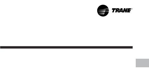
Operating Torque
Chart illustrates low torque variation of the Trane scroll compressor vs reciprocating compressor.
Features and World Class Efficiency
Benefits & Reliability
Leading in Efficiency and Reliability with State-Of-The-Art Scroll Compressor Technology
Efficiency
The energy efficiency of the scroll chiller results in energy costs lower than any other comparable chiller. Full load efficiencies are improved beyond reciprocating chillers, but part load efficiencies are simply unmatched by any other manufacturer.
Superior efficiencies are obtained by combining many of the traditional scroll chiller energy efficient features with the Trane scroll compressor technology. HERE’S HOW:
•Scroll compressor’s positive displacement design
•Dual refrigerant circuits (40-60 ton units)
•Multiple compressors
•Optimum system design
•Reduced friction
•No valves
•Advanced heat transfer surfaces
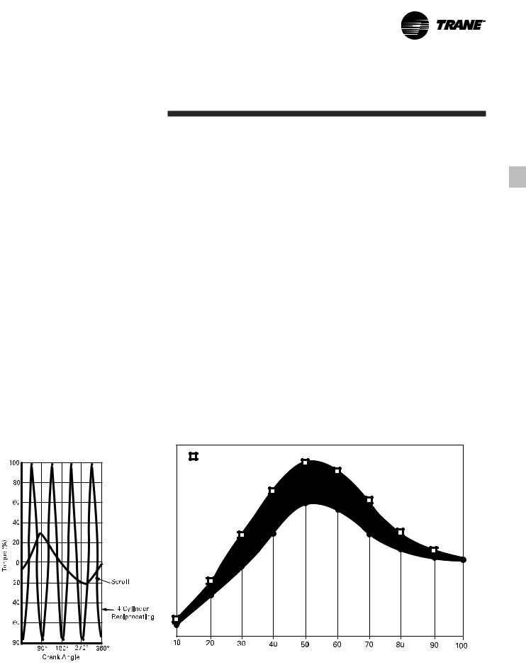
Scroll Chiller Energy Usage Savings
Reliability
The Trane scroll chiller with many new improvements, now brings an exciting new compressor to the commercial market — the Trane scroll compressor. Trane has designed the scroll compressor to be a leader in reliability. HERE’S HOW:
•Simple design with 64 percent fewer parts than equal capacity reciprocating compressor.
•Scroll compliance allows liquid and dirt to pass through without damaging compressor (liquid slugging resistant).
•Advanced microelectronics protect both compressor and motor from typical electrical fault conditions.
•Scroll compressors have less than a third the torque variations of a reciprocating compressor.
•Years of laboratory testing have optimized compressor and chiller systems reliability.
•Water-cooled scroll chillers are factory tested.
Typical Reciprocating |
10-20% Annual Energy Savings |
Chiller |
|
 Scroll Chiller
Kilowatt Hours
Chiller Load (%)
Graph illustrates Trane scroll chiller’s superior annual energy costs vs typical reciprocating chillers.
CG-PRC012-EN |
5 |

Features and World Class Efficiency
Benefits & Reliability
Trane Scroll Compressor
— Maximum Efficiency with Enhanced Reliability
General
The scroll compressor has two scrolls. The top scroll is fixed and the bottom scroll orbits. Each scroll has walls in a spiral shape that intermesh.
Inlet-First Orbit
As the bottom scroll orbits, two refrigerant gas pockets are formed and enclosed.
Compression-Second Orbit
The refrigerant gas is compressed as the volume is reduced closer to the center of the scroll.
Discharge-Third Orbit
The gas is compressed further and discharged through a small port in the center of the fixed scroll.
Scroll Principal Components
This is a cutaway view of a hermetic, scroll compressor, showing the relative positions of the principal components. Shown is a Trane 10-ton, 3600 rpm, 60 Hz [3000 rpm, 50 Hz] scroll compressor as an example.
The principle of operation of this example compressor is as follows: The suction gas is drawn into the compressor at A. The gas then passes through the gap between the rotor and stator, B, cooling the motor, before it enters the compressor housing, C. Here, the velocity of the gas is reduced, causing a separation of the entrained oil from the gas stream. The gas then enters the intake chamber, D, that encircles the scrolls.
Finally, the suction gas is drawn into the scroll assembly where it is compressed and discharged into the dome of the compressor. The dome of this example compressor acts as a hot gas muffler which dampens the pulsations before the gas enters the discharge line, E.
6 |
CG-PRC012-EN |
Features and
Benefits Options
Options
Hot Gas Bypass: Hot gas bypass option allows unit operation below the minimum step of unit unloading. The regulator valve, along with all associated refrigerant piping and electrical wiring, are factory installed and tested on one refrigeration circuit. Unit does not start in hot gas bypass mode. If the unit operates in bypass mode for 30 minutes without a call for cooling, it will pump down and shut off. Unit starts immediately upon a further call for cooling.
Chilled Water Reset: Front panel settable control, microprocessor based control strategy, and field-installed sensor for ambient temperature based reset are included in this option. Return water reset sensor is standard, but panel controller and control strategy must be ordered as an option.
Tracer Summit Communication Interface: Permits bi-directional communication to the Trane Integrated Comfort system.
LonTalk LCI-C Communication Interface:
Provides the LonMark chiller profile inputs/outputs for use with a generic building automation system.
Remote Input Options
Remote chilled water setpoint input (4-20mA/2-10Vdc), compressor inhibit which locks out the second compressor on each circuit reducing the kW draw or both.
Control Output Options
Programmable relays provided to indicate: Compressor running, maximum capacity, chiller limit mode, warning (informational diagnostic), alarm latching (shutdown diagnostic), alarm nonlatching (shutdown diagnostic), alarm latching or nonlatching.
Ice Making Controls: In ice-making mode, the unit will operate fully loaded in response to jobsite supplied contact closure. Ice making will terminate when the return fluid temperature falls below an adjustable setpoint (minimum 20°F [-6.7°C]). When not in ice making mode, unit will provide modulating capacity control based on leaving chilled fluid temperature (20-55°F) [-6.7°C to 12.8°C].
Unit Mounted Disconnect Switch: Nonfused molded case disconnect switch factory installed in control panel for disconnecting main three-phase power.
Isolators: Neoprene-in-shear isolators for field installation under unit frame.
Sound Attenuation: Factory-installed acoustical attenuation for applications where extremely low sound level is required.
Water Regulating Valves: Field-installed valves provide means for control of head pressure.
Outdoor Temperature Sensor: Fieldinstalled outdoor temperature sensor with an adjustable setpoint provides means for low ambient lockout.
Condenser Water Temperature Sensor:
Factory installed temperature sensor provided for microprocessor display.
CG-PRC012-EN |
7 |
Controls
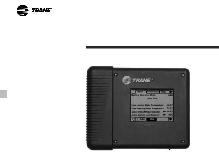
Human Interfaces
The Trane water-cooled 20-60 ton scroll CGWF chiller offers an easy-to-use operator interface panel, the DynaView.
DynaView is an LCD touchscreen display that is navigated by file tabs. This is an advanced interface that allows the user to access any important information concerning setpoints, active temperatures, modes, electrical data, pressures, and diagnostics.
Safety Controls
A centralized main processor offers a higher level of machine protection. Since the safety controls are smarter, they limit compressor operation to avoid compressor or evaporator failures, thereby minimizing nuisance shutdown. Tracer™ Chiller Controls (CH530) directly senses the control variables that govern the operation of the chiller: evaporator pressure and condenser pressure. When any one of these variables approaches a limit condition where damage may occur to the unit or shutdown on a safety, Tracer Chiller Controls takes corrective action to avoid shutdown and keep the chiller operating. This happens through compressor shedding. Tracer Chiller Controls optimizes total chiller power consumption during normal operating conditions. During abnormal operating conditions, the microprocessor will continue to optimize chiller performance by taking the corrective action necessary to avoid shutdown. This keeps cooling capacity available until the problem can be solved. Whenever possible, the chiller is allowed to perform its function; making chilled water. Overall, the safety controls help keep the building or process running and out of trouble.
Figure C1. DynaView operator interface
Standalone Controls
Interface to standalone units is very simple; only a remote auto/stop for scheduling is required for unit operation. Signals from the chilled water pump contactor auxiliary or a flow switch are wired to the chilled waterflow interlock. Signals from a time clock or some other remote device are wired to the external auto/stop input.
Standard Features
•External Auto/Stop — A jobsite provided contact closure will turn the unit on and off.
•Chilled Water Flow Interlock — A jobsite provided contact closure from a chilled water pump contactor and/or a flow switch is required and will allow unit operation if a load exists and flow is proven. This feature will allow the unit to run in conjunction with the pump system.
•Emergency Stop — A jobsite supplied contact opening wired to this input will turn the unit off and require a manual reset of the unit microcomputer. This closure is typically triggered by a jobsite supplied system such as a fire alarm.
•Chilled Water Pump Control — Unit controls provide an output to control the chilled water pump(s). One contact closure to the chiller is all that is required to initiate the chilled water system.
•Chilled Water Temperature Reset —
Reset can be based on return water temperature or outdoor air temperature (optional).
•Condenser Water Pump Control — Unit controls provide an output to control the condenser water pump(s). One contact closure to the chiller is all that is required to initiate the chilled water system.
•Condenser Water Flow Protection — A jobsite supplied contact closure from a flow switch or pressure switch is required and will shut down the unit if flow is lost.
8 |
CG-PRC012-EN |
Controls
Easy Interface to A Generic Building Management System
Controlling the scroll CGWF chiller with building management systems is state- of-the-art, yet simple with either the LonTalk Communications Interface for Chillers (LCI-C) or Generic Building Management System Hardwire Points.
Simple Interface with Other Control Systems
CH530 controls afford simple interface with other control systems, such as time clocks, building automation systems, and ice storage systems. This means you have the flexibility to meet job requirements while not having to learn a complicated control system. This setup has the same standard features as a stand-alone water chiller, with the possibility of having additional optional features.
What are LonTalk, Echelon, and LonMark?
LonTalk is a communications protocol developed by the Echelon Corporation. The LonMark association develops control profiles using the LonTalk communication protocol. LonTalk is a unit level communications protocol, unlike BACNet used at the system level.
LonTalk Communications Interface for Chillers (LCI-C)
LonTalk Communications Interface for Chillers (LCI-C) provides a generic automation system with the LonMark chiller profile inputs/outputs. The inputs/ outputs include both mandatory and optional network variables. Note: LonMark network variable names are in parentheses when different from chiller naming convention.
Chiller Inputs:
•Chiller Enable/Disable
•Chilled Liquid Setpoint (Cool Setpoint)
•Compressor Inhibit
•Chiller Mode (Ice Making)
Chiller Enable/Disable
Allows for chiller to be started or stopped depending on if certain operating conditions are met.
Chilled Water Setpoint
Allows for the external setting independent of the front panel setpoint to adjust the leaving water temperature setpoint.
Compressor Inhibit
Locks out the second compressor on each circuit, reducing the kW draw.
Ice Making
Provides interface with ice making control systems. Please refer to page 11 for more information.
Chiller Outputs:
•On/Off
•Active Setpoint
•Average Percent RLA
•Compressor Inhibit
•Compressor Starts
•Compressor Run Times
•Leaving Chilled Water Temperature
•Entering Chilled Water Temperature
•Evaporator Refrigerant Temperature
•Evaporator Refrigerant Pressure
•Evaporator Water Pump Request & Flow Status
•Leaving Condenser Water Temperature
•Entering Condenser Water Temperature
•Condenser Refrigerant Temperature
•Condenser Refrigerant Pressure
•Condenser Water Pump Request & Flow Status
•Outdoor Air Temperature (CCAF)
•Alarm Descriptor
•Chiller Status
Active Setpoint
Indicates the current value of the leaving water temperature setpoint
Average Percent RLA
Provides the current capacity level via % RLA
Compressor Starts and Run Times
Provides the number of starts and run time for each compressor
Alarm Descriptor
Provides alarm messages based on predetermined criteria
Chiller Status
Indicates the running modes and states of the chiller, i.e. Running in alarm mode, chiller enabled, chiller being locally controlled, etc…
Generic Building Management System Hardwire Points
GBAS may be achieved via hardware input/output as well. The input/outputs are as follows:
Chiller Hardwire Inputs Include:
•Chiller Enable/Disable
•Circuit Enable/Disable
•External Chilled Water Setpoint
•Compressor Inhibit
•Ice Making Enable
Programmable Relays and Alarms
The unit provides seven output options, of which four can be chosen.
a) Compressor running indication b)Maximum capacity
c) Chiller limit mode
d)Warning informational diagnostic indication
e)Alarm latching shutdown diagnostic indication
f)Alarm nonlatching shutdown
diagnostic indication g)Alarm latching or nonlatching
shutdown diagnostic indication
CG-PRC012-EN |
9 |
Controls
Tracer Summit controls — Interface With The Trane Integrated Comfort System (ICS)
Trane Chiller Plant Control
The Tracer Summit Chiller Plant Building Management System with Chiller Plant Control provides building automation and energy management functions through stand-alone control. The Chiller Plant Control is capable of monitoring and controlling your entire chiller plant system.
Application software available:
•Time-of-day scheduling
•Demand limiting
•Chiller sequencing
•Process control language
•Boolean processing
•Zone control
•Reports and logs
•Custom messages
•Run time and maintenance
•Trend log
•PID control loops
And of course, the Trane Chiller Plant Control can be used on a stand-alone basis or tied into a complete building automation system.
When the scroll CGWF chiller is used in conjunction with a Trane Tracer™ Summit system, the unit can be monitored and controlled from a remote location. The chiller can be controlled to fit into the overall building automation strategy by using time of day scheduling, timed override, demand limiting, and chiller sequencing. A building owner can completely monitor the chiller from the Tracer system, since all of the monitoring information indicated on the unit controller’s microcomputer can be read off the Tracer system display. In addition, all the powerful diagnostic information can be read back at the Tracer system. Best of all, this powerful capability comes over a single twisted pair of wires! The scroll liquid chillers can interface with many different external control systems, from simple stand-alone units to ice making systems.
A single twisted pair of wires tied directly between the CGWF chiller and a Tracer™ Summit system provides control, monitoring and diagnostic capabilities. Control functions include auto/stop, adjustment of leaving water temperature setpoint, compressor operation lockout for kW demand limiting and control of ice making mode. The Tracer system reads monitoring information such as entering and leaving evaporator water temperatures and outdoor air temperature. Over 60 individual diagnostic codes can be read by the Tracer system. In addition, the Tracer system can provide sequencing control for up to 25 units on the same chilled water loop. Pump sequencing control can be provided from the Tracer system. Tracer ICS is not available in conjunction the external setpoint capability.
Required Options
Tracer Interface
External Trane Devices Required
Tracer Summit™, Tracer 100 System or Tracer Chiller Plant Control
Additional Features That May Be Used
Ice Making Control
10 |
CG-PRC012-EN |
Controls
Trane Chiller Plant Automation
Trane’s depth of experience in chillers and controls makes us a well-qualified choice for automation of chiller plants using scroll liquid chillers. The chiller plant control capabilities of the Trane Tracer Summit® building automation system are unequaled in the industry. Our chiller plant automation software is fully pre-engineered and tested. It is a standard software application, not custom programming which can prove to be difficult to support, maintain, and modify.
Energy Efficiency
Trane chiller plant automation intelligently sequences starting of chillers to optimize the overall chiller plant energy efficiency. Individual chillers are designated to operate as base, peak, or swing based on capacity and efficiency. Sophisticated software automatically determines which chiller to run in response to current conditions. The software also automatically rotates individual chiller operation to equalize runtime and wear between chillers.
Trane chiller plant automation enables unique energy-saving strategies. An example is controlling pumps, and chillers from the perspective of overall system energy consumption. The software intelligently evaluates and selects the lowest energy consumption alternative.
Keeping Operators Informed
A crucial part of efficiently running a chiller plant is assuring that the operations staff is instantly aware of what is happening in the plant. Graphics showing schematics of chillers, piping, pumps, and towers clearly depict the chiller plant system, enabling building operators to easily monitor overall conditions. Status screens display both current conditions and upcoming automated control actions to add or subtract chiller capacity. CGWF and other chillers can be monitored and controlled from a remote location.
Tracer Summit features standard report templates listing key operating data for troubleshooting and verifying performance. Reports for each type of Trane chiller and three and six-chiller systems are also standard. Detailed reports showing chiller runtimes aid in planning for preventative maintenance.
Swift Emergency Response
We understand the importance of maintaining chilled water production while protecting your chillers from costly damage. If no water flow is detected to a chiller’s piping, the start sequence is aborted to protect the chiller. The next chiller in the sequence is immediately started to maintain cooling.
In the event of a problem, the operator receives an alarm notification and diagnostic message to aid in quick and accurate troubleshooting. A snapshot report showing system status just prior to an emergency shutdown helps operators determine the cause. If emergency conditions justify an immediate manual shutdown, the operator can override the automatic control.
Easy Documentation for Regulatory Compliance
Comprehensive documentation of refrigerant management practices is now a fact of life. Trane chiller plant automation generates the reports mandated in ASHRAE Guideline 3.
Integrated Comfort™ Capabilities
When integrated with a Tracer Summit building management system performing building control, Trane chiller plant automation coordinates with Tracer Summit applications to optimize the total building operation. With this system option, the full breadth of Trane’s HVAC and controls experience are applied to offer solutions to many facility issues. If your project calls for an interface to other systems, Tracer Summit can share data via BACnet™, the ASHRAE open systems protocol.
Ice Making Systems Controls
An ice making option may be ordered with the 20-60 ton scroll liquid chiller. CH530 will accept a command to initiate ice making. When in the ice making mode, the chiller will be fully loaded and will continue to operate until the ice command is removed or the evaporator entering water temperature reaches the active ice termination setpoint. If terminated on the evaporator entering water temperature, CH530 will not allow the chiller to restart until the ice making command is removed.
Additional Options That May Be Used In
Conjunction
Failure Indication Contacts
Communications Interface (For Tracer
Systems)
Chilled Water Temperature Reset
CG-PRC012-EN |
11 |
Application
Considerations
Unit Location
Units should be installed indoors where exposure to rain or water splash is minimal. A level foundation or flooring must be provided which will support at least 150 percent of the operating weight of the unit. The chiller foundation must be rigid to reduce vibration transmission to a minimum. Use of vibration isolators is recommended for applications with sensitive vibration and noise criteria.
Allow service clearance for compressor removal as well as evaporator and condenser tube removal.
Condenser Water Limitations
Water-cooled scroll chillers start and operate satisfactorily over a range of load conditions with uncontrolled entering water temperature.
Reducing the condenser water temperature is an effective method of lowering the power input required. However, by reducing the condenser water temperature beyond certain limits, the effect causes a reduction in the pressure drop across the thermal expansion valve to a point when system instability may occur.
In general, continuous machine operation with entering condenser water temperature below 60°F [15.5°C] is not recommended. When the condenser water temperature is expected to drop below 60°F [15.5°C], it is recommended that some form of condenser water temperature control be used to ensure optimal machine performance.
Water Treatment
Use of untreated or improperly treated water in chillers may result in scaling, erosion, corrosion, algae or slime. It is recommended that the services of a qualified water treatment specialist be engaged to determine what treatment, if any, is advisable. Trane assumes no responsibility for the results of untreated, or improperly treated water.
Water Pumps
Avoid specifying or using 3600 rpm, 60 Hz [3000 rpm, 50 Hz] condenser water and chilled water pumps. Such pumps may operate with objectional noise and vibration. In addition, a low frequency beat may occur due to the slight difference in operating rpm between water pumps and scroll compressor motors. Where noise and vibration-free operation is important, Trane encourages the use of 1750 rpm, 60 Hz [1450 rpm, 50 Hz] pumps.
Remote Condenser
Remote condensers should be located as close as possible to the chiller to ensure minimum pressure drops of discharge refrigerant. If non-Trane condensers are provided, a subcooling circuit must be provided in order to achieve cataloged performances (16°F [-8.9°C] subcooling).
12 |
CG-PRC012-EN |
 Loading...