


Leica AG, CH-9435 Heerbrugg (Switzerland) Telephone +11 (071) 70 31 31, Fax +41 (071) 72 69 52
Leica is a registered trade mark of Leica technologij B. V. Rijswijk, the Netherlands
|
|
|
Legal matters |
|
|
|
|
|
|
|
|
|
|
|
|
|
|
|
|
|
Revisions/Service News |
|
|
|
|
|
|
|
|
|
|
|
|
|
|
Service Manual |
|
|
|
Introduction / User manual |
|
|
|
|
|
|
|
|
|
|
|
|
|
WILD M695 |
|
|
Fault finding with testset |
|
|
|
|
|
|
|
|
|
|
|
|
|
|
|
|
|
Control unit MEL61/62, MEL64/65 |
5 |
|
|
||
|
|
|
|
|
|
|||
|
|
|
|
|
|
|
|
|
|
|
|
|
Swingarm MSV 136/137 |
6 |
|
|
|
|
|
|
|
|
|
|
|
|
|
|
|
|
Microscope M695 |
7 |
|
|
|
|
|
|
|
|
|
|
|
|
|
|
|
|
|
8 |
|
|
|
|
|
|
|
|
|
|
|
|
|
|
|
|
Wiring diagram |
9 |
|
|
|
|
|
|
|
|
|
|
|
|
|
|
|
|
Replacing modules |
|
|
|
|
|
|
|
|
|
|
|
|
|
|
|
|
|
Replacing boards |
|
|
|
|
|
|
|
|
|
|
|
|
|
|
|
|
|
Inspection procedure |
12 |
|
|
|
|
|
|
|
|
|
|
|
|
|
|
|
|
|
13 |
|
|
|
|
|
|
|
|
|
|
|
|
|
|
|
|
|
14 |
|
|
|
|
|
|
|
|
|
|
||
|
|
|
|
|
15 |
|
||
|
|
|
|
|
|
|
||
|
|
|
|
|
16 |
|
||
|
|
|
|
|
|
|
||
|
|
|
|
Training |
17 |
|
||
|
|
|
|
|
|
|
|
|
|
|
|
|
Testset |
|
|
|
|
|
|
|
|
|
|
|
||
|
|
|
|
Spare parts catalogue |
19 |
|
||
|
|
|
|
|
|
|||
|
|
|
|
Special tools |
20 |
|||

Service Manual M695 |
Legal questions/ Safty-Rechtsfragen / |
Sicherheit |
Doc Code 636 718 |
09/93 |
3691-DMF |
lnhaltsvetzeichnis / Table of contents
Kapitel |
Seite |
Rechtsfragen / Legal questions ...................................................................................... |
1 |
Sicherheit / Safety / Securite / Seguridad....................................................................... |
3 |
Service Manual M695 |
Legal questions / Safty-Rechtsfragen / Sicherheit |
Doc Code 636 718 |
09/93 3691-DMF |
Copyright
Ohne vorherige schriftliche Erlaubnis der Firma Leica AG, Heerbrugg (Schweiz), darf dieses Dokument weder insgesamt noch auszugsweise mit mechanischen, fotografischen, elektronischen oder irgendwelchen anderen Mitteln (einschließlich ihrer Umwandlung oder Übertragung in maschinenlesbarer Form) kopiert, in einem Informationsspeicher abgelegt, außerhalb des dafür vorgesehenen Zwecks oder in irgend einer Form an von Leica AG, Heerbrugg nicht ausdrücklich befugte Dritte zuganglich gemacht oder abgegeben werden.
Haftung
Dieses Dokument richtet sich ausschließlich an qualifizierte Servicetechniker und Servicetechnikerinnen, welche über die notwendigen Fachkenntnisse verfugen.
Qualifizierte Servicetechniker und Servicetechnikerinnen sind solche, die den entsprechenden Servicekurs bei Leica AG, Heerbrugg erfolgreich besucht haben und bei Unternehmen der Leica Gruppe oder bei von Leica AG, Heerbrugg autorisierten Vertretungen oder Servicewerkstätten tätig sind.
Wird dieses Dokument von nicht qualifizierten Servicetechniker und Servicetechnikerinnen verwendet, so lehnt Leica AG, Heerbrugg jegliche Haftung ab für direkte und indirekte Schaden, die durch nicht fachgemäße Anwendung und/oder Interpretation dieses Dokumentes entstehen.
Copyright
Without prior permission in writing by Leica AG, Heerbrugg (Switzerland), this document shall not be reproduced as a whole or in part, by mechanical, photographic, electronic, or other means (including into or transmission in machine-readable form); stored in any retrieval system; used for any purpose other than that/those for which it is intended; nor made accessible or communicated in any form to any third party not expressly authorized by Leica AG, Heerbrugg to have access thereto.
Liability
This document is strictly for the use of qualified service engineers with the requisite technical skills. Only persons who have successfully completed the appropriate service training provided by Leica AG,
Heerbrugg and are in the employ of a Company in the Leica Group or of an agency, distributor, or Service Workshop duly authorized by Leica AG, Heerbrugg have the status of qualified Service engineer.
Leica AG, Heerbrugg accepts no liability whatever for direct or indirect damage that may occur due to the unauthorized or improper use or interpretation of this document by any person who is not a qualified service engineer in accordance with the above definition.
Service Manual M695 |
Legal questions / Safty-Rechtsfragen / Sicherheit |
Doc Code 636 718 |
09/93 3691-DMF |
Für die Servicetechniker und Servicetechnikerinnen gelten folgende Pflichten:
•Sie verstehen und befolgen die Sicherheitsinformationen und die Instruktionen auf dem Produkt sowie in der Gebrauchsanleitung.
•Sie kennen die ortsüblichen gesetzlichen, betrieblichen und ausserbetrieblichen
Unfallverhütungsvorschriften im Wissen, dass sich diese auf dem aktuellsten Stand |
befinden. |
• Sie benachrichtigen Leica schriftlich, sobald an der Ausrüstung Sicherheitsmangel |
auftreten. |
Service technicians have the following obligations:
•To understand and follow the safety information and instructions on the product and in the user manual.
•To be familiar with local regulations relating to industrial and non-industrial accident prevention in the knowledge that these regulations are up to date.
•To inform Leica immediately in writing if the equipment becomes unsafe.
October 94
Leica AG, Heerbrugg
R E V I S I O N
Documentation |
: WILD M695 Service manual |
|
|||||||
|
|
|
(Technical description and fault finding) |
|
|||||
Status |
: Edition 09(93 |
/ |
Revision, previous: ------- |
|
|||||
|
|
|
|
|
|
|
new: 10/94 |
|
|
Reason for revision : M680 control unit (MEL61/62) is compatible with M695 |
|
||||||||
Steps to be taken |
: |
|
|
|
|
|
|
||
|
|
|
|
|
|
|
|
|
|
|
Section |
|
Remove page(s) |
Number of |
|
Introduce page(s) |
|
Number of |
|
|
|
|
|
|
sheets |
|
|
|
sheets |
|
|
|
|
|
|
|
|
|
|
|
--- |
|
title |
sheet |
1 |
|
title sheet |
|
1 |
|
--- |
|
index |
register |
1 |
|
index register |
|
1 |
|
2 |
|
|
--- |
-- |
|
2-1/2 |
|
1 |
|
9 |
|
9-1 to 9-8 |
4 |
|
9-1 to 9-8 |
|
4 |
|
|
19 |
|
19-1 |
1 |
|
19-1 |
|
1 |
|
File |
: Insert this sheet (Revision) in section 2. |
|
|||||||
Leica AG
Service Documentation
and Training LSG/SOM/SM
SOM and SM Service News
Surgical Operating Microscopes
No. 10/95
To Service staff
Date/from June 28, 1995 / 3077-HWE
File Workshop binder “Service News” / Service manual M695
Re. M695 surgical microscope in conjunction with multifocus objective 445 944
Leica AG
CH-9435 Heerbrugg
(Switzerland)
Restriction of illuminated area
lnspect the illumination
Multifocus objective on M695:
Readjustment of the illumination
When the multifocus objective is used with the M695, the illuminated area available to the surgeon may be shadowed or vignetted even when the the lamp is correctly adjusted.
When you use the multifocus objective for the first time, inspect the illumination:
•Engage the shortest working distance (the shortest focal length).
•Engage the lowest zoom position (7).
•Inspect the illuminated fields produced by both of the lamps in the lamp changer.
•If the illuminated area is noticeably restricted, readjust the lamps.
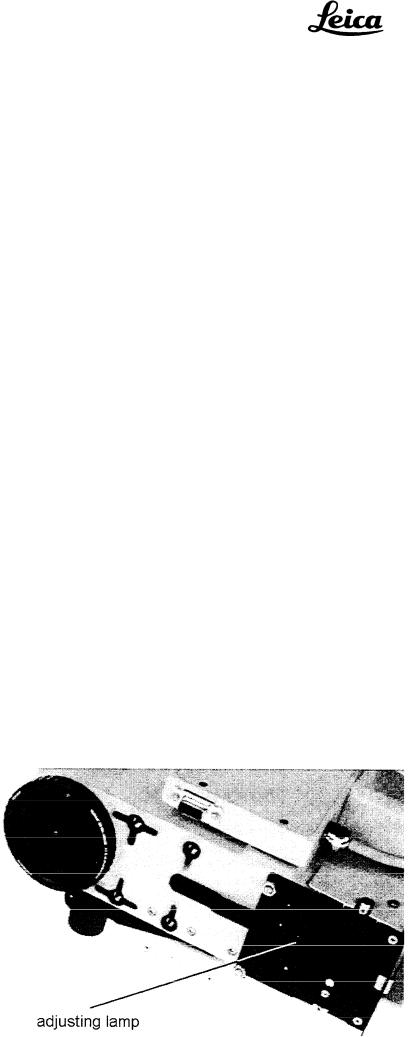
Readjusting the lamp |
The illumination of the field of view is influenced by the distance |
|
between the lamp and the condenser lens. This distance can be changed |
|
by means of the eccentric stop cam on the lamp changer. To obtain |
|
uniform illumination, reduce the distance between the lamp and the |
|
condenser lens. |
|
Adjust the eccentric stop cam for both lamps in the lamp changer: |
|
1. Remove the multifocus objective and push the filter slide of the |
|
M695 optics carrier towards the objective. Beneath the filter slide |
|
you will find the adjusting screw for the eccentric stop cam. |

2 . Using a screwdriver, displace the eccentric stop cam by about oneeighth of a turn so that the lamp can be moved in the direction of the objective.
CAUTION: The lamp may be hot.
3.Switch to the second lamp, and carry out point 2 for this lamp.
4.Refit the multifocus objective and inspect the illumination as described above.
5. If necessary, repeat the adjustment procedure (points 1 - 3).
Leica AG
Service SOM/SM
W. Hammerle

SOM and SM Service News
No. 09 / 95 |
Leica AG |
|
CH-9435 Heerbrugg |
To Service staff |
(Switzerland) |
Date/from May 29, 1995 / BKL-3402 |
|
File Workshop binder “Service News” / Service Manual M695 |
|
Refer to Necessary replacement of SOM product “Light intensifier” |
|
No. 445 796 |
|
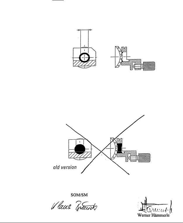
Delivery of faulty SOM product "Light intensifier” 445 796
Faulty product has to be exchanged
The concerned product has been delivered to the following countries as single part or included in the delivery of optics carriers:
Netherlands, Japan UK, Italy, Australia, USA, Sweden, Canada, Switzerland, Korea, South Africa, Kuwait, Belgium, Spain Columbia, Saudi Arabia, France, Singapore, Finland, Portugal, Germany, Denmark, Algeria, Sudan, Luxembourg, Dominikanische Republic, Hong Kong, Turkey, Brazil, Tunisia, Israel, Austria, Jordanian India.
All other countries are not concerned.
Problem:
Action:
Since market introduction in March 1994 up to March 1995 the concerned product has been delivered faulty (The cement does not withstand the high temperatures at the bulb). It has been delivered as a single part as well as included in the following optics carriers:
M690 |
optics carrier Mitaka |
445 543 |
M695 |
optics carrier |
445 560 |
M695 |
optics carrier Mitaka OH 445 841 |
|
Since March 1995 an improved version with the same No. has been delivering. The two versions can be distinguished easily according to the drawing on page two.
The concerned customers are already informed by your Management.
The faulty products have to be replaced, please contact your Marketing responsible for SOM products.
All concerned countries will be supplied automatically without any order with sufficient replacement units, free of charge.
The exchange procedure is very simple and can be achieved by the customer himself as well. If you will not carry out the exchange yourself, supply the customer with sufficient exchange units and Information.
SERNEWSE.DOC |
1/2 |
Service manual M695 |
Modification |
Doc Code 636 718 |
10/94 3077-HWE |
Changes and modifications
M680 control unit (MEL61/62) is compatible with
M695 surgical microscope
. . . from control unit the MEL61/62 can also be used for the M695, provided that earlier lamp serial number 011193001 control PCBs are subjected to a slight modification. This modification was
onwards introduced from March 1993 onwards (Index C on board) (355 980 C).
The functions ZOOM SPEED B, XY-SPEED and POSITION 1/2 are not required for the M695. The positions occupied on the control panel by these switches or potentiometers will be covered over. The covers, and instructions for fitting them, accompany the control unit.
From March 1995 onwards, only the MEL61/62 control unit will be used for the M680 and M695. The previously-used MEL64/65 control unit will no longer be manufactured.
Modification of the is required if both of the following conditions are met: lamp-conbol PCB
1.The MEL64/65 control unit is replaced by an MEL61/62
2.The M695 was despatched before March 1993. The lamp control PCB therefore bears an earlier index than C.
Under these conditions the hand-/footswitches will not react at the control input A or B respectively, depending on the position of the switch "Position 1/2".
Modification: On the soldered side, bridge pins 10 and 12 of P20 with a 100 Ω resistor (1/8W). The resistor shall not come into contact with the housing cover.
2-1

Modifications |
Service manuel WILD M695 |
10/94 3077-HWE |
Doc Code 636 718 |
2-2

Service Manual M680 |
Introduction |
Doc code 556 848 |
03/93 3077-HWE |
|
|
Preconditions
for using this service manual
Intended users |
Technical personnel provided by customer or by LEICA agencies, equipped |
|
with the testset 566 152 (see Section 18). |
What is expected of |
Stage 1: Allocation of a fault to one of the main groups: |
|
the person using the |
- |
Footswitch |
Testset? |
||
|
- |
Control unit |
|
- |
Swingarm |
|
- |
Microscope (optics carrier) |
• You have read the user manual and can operate the surgical microscope Directions are given in Sections 3 and 4.
Stage 2: Locating and eliminating errors at module level
•You have been trained in the basics of electronics and mechanical engineering
•You have been instructed by a technician from your agency or from LEICA AG, HEERBRUGG.
Sections 3,4 and 10
Stage 3: Locating and eliminating errors at board level
•You have been trained in the basics of electronics and mechanical engineering
•You have taken part in an M690/M695or M680 course.
Sections 3 to 9, and Section 11
3-1

Introduction |
Service Manual M680 |
03/93 3077-HWE |
Doc code 656 948 |
|
|
Legal aspects
Changes/
Service News
Introduction/
User manual
locating faults with the test set (Test box)
Control unit MEL64165 Description of function
To the contents of service manual
This book may only be given to, and used by, certain persons. These are detailed in Section 1.
Place Service News on top of the M695 in Section 2.
CONGRATULATIONS - You are one of those methodical people who also read the important Section 3 of this manual.
If a fault develops, we will guide you to it with the assistance of Section 4 and the test box.
The test set helps you to assign the fault to the:
•Footswitch
•Control unit
•Swingarm
•Microscope
The search is then continued at board level with the assistance of block diagrams and the wiring diagram.
The function description in Section 5, in conjunction with the wiring diagram, will lead you to the defective board or cable connection. The swingarm is the interface.
3-2

Service Manual M680 |
Introduction |
|
Doc code 556 948 |
03/93 3077-HWE |
|
|
|
|
Swingarm
Description of function
M680 microscope
Description of function
Wiring diagram
Exchanging modules
Exchanging boards
Testing procedure
Test set
The function description in Section 6, in conjunction with the wiring diagram, will lead you to the defective board or cable connection. The swingarm is the interface.
The function description in Section 7, in conjunction with the wiring diagram, will lead you to the defective board or cable connection. The swingarm is the interface.
Section 9 contains the wiring diagram, and a description of the positions of the boards and the plug connections.
Section 10 includes instructions for exchanging those modules which are available as spare parts.
Section 11 includes instructions for exchanging those boards which are available as spare parts.
After modules or boards have been replaced, the instrument must meet specifications. Values and tolerances are laid down in the testing procedure in Section 12.
The test box and service cable, and their circuits, are described in Section 18.
Spare parts |
The spare parts, the exchange of which is described in Sections 8 and 9, are |
|
listed in Section 19. |

Introduction |
Service Manual M680 |
03/93 3077-HWE |
Doc code 556 948 |
|
|
Special tools |
Section 20 includes a list of the service equipment which will enable you to |
|
carry out the operations described above. |
|
No special tools are required. The components making up the test box include |
|
a service handswitch and a service cable which serves to bridge the swingann. |
3-4

User Manual |
Service Manual M695 (CD-ROM) |
08/98 |
Doc code 636 718 |
|
|
The M695 User Manual is provided as a separate document. To view it, click on this text.

Service manual M695 |
M695 fault finding |
Doc code 636 718 |
09/93 3077-HWE |
|
|
Table of content
M695 fault finding
Chapter |
Page |
|
Preparation |
4-1 |
|
Power supply of control unit |
4-3 |
|
Functions of handor footswitch |
4-4 |
|
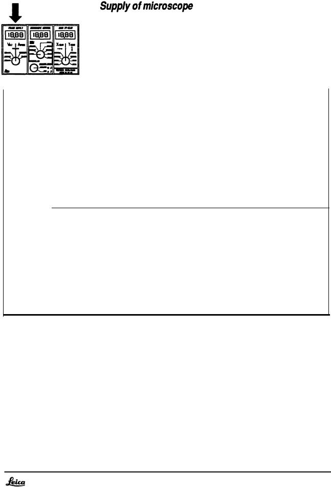
Supply |
of microscope |
4-5 |
Lamp |
control |
4-7 |
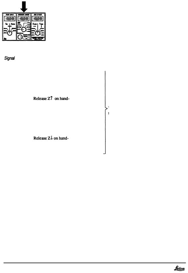
Zoom |
control |
4-8 |
Focus |
control |
4-9 |
Service manual M695 |
M695 Fault finding |
|
Doc code 636 718 |
09/93 3077-HWE |
|
|
|
|
M695 Fault finding
Preparation
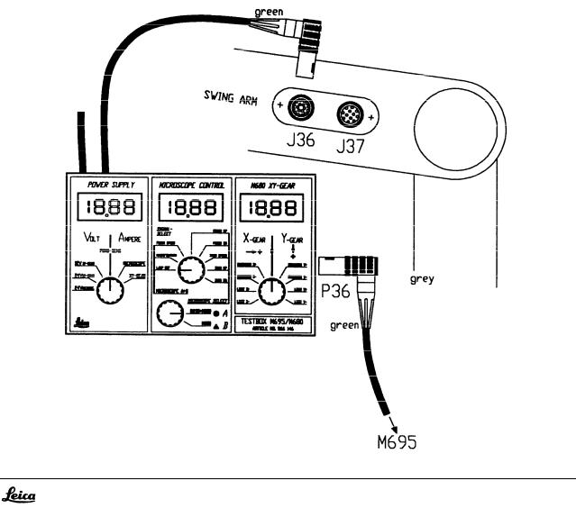
1. Connecting the testbox
•
•
•
•
Disconnect plug P36 from swingarm
Hook in the testbox to the swingarm and plug in P36 at the testbox.
Connect the testbox cable (green sleeve) with J36 at the swingann. With that the control unit is connected with the microscope through the testbox.
Set switch “MICROSCOPE SELECT” on the testbox to position A.
4-1
M695 |
Fault finding |
Service manual M695 |
09/93 |
3077-HWE |
Doc code 636 718 |
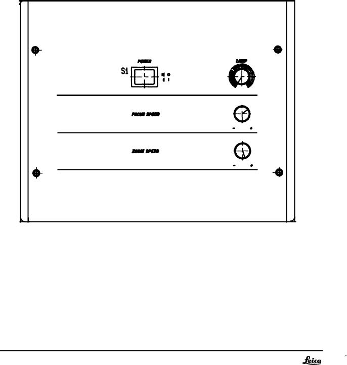
2. Settings on the control unit
•Adjust Lamp to minimal brightness
4-2
M695 Fault finding |
Service manual M695 |
09/93 3077-HWE |
Doc code 638 718 |
|
|
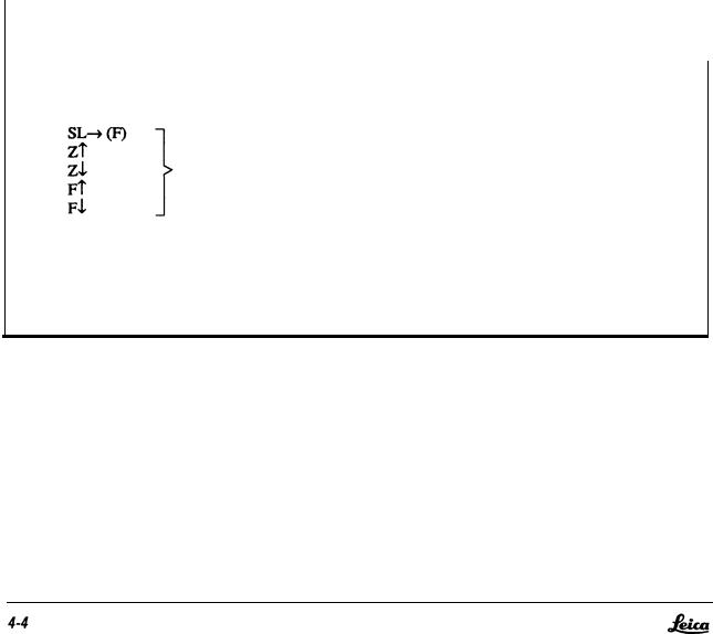
Functions of handor footswitch
Condition: Malfunction of handor footswitch of only one of the two CONTROL-inputs, A or B
is disturbed.
•Replace disturbed handor footswitch ective side A or B by either:
a)Service-handswitch or
b)Hand-/footswitch at the other CONTROL-input
|
Action |
Reaction |
Possible reason |
|
|
|
|
Release functions:
Corresponding LED at |
Function |
Display does not light |
Receiver Board |
Connect again original switch |
Corresponding LED at Function Handor footswitch |
a n d |
Display does not light |
release functions |
|
Service manual M695 |
M695 Fault finding |
Doc code 636 718 |
09/93 3077-HWE |
|
|
Voltage |
Action |
R e a d i n g |
Reaction |
Possible fault |
|
|
|
|
|
24V M I C R O |
1.Lamp to min.brightness |
|
2.Lamp to max.brightness |
|
3.Lamp back to min. |
|
brightness |
26V |
+-5% |
Microscope reacts - |
Check supply- |
20V |
+-5% |
but incorrect |
lines of 24V and |
|
|
|
check PGND - |
|
|
|
page 4-6 |
|
|
Microscope without |
Wiring of |
|
|
any function |
microscope |
Switch off, bridge swing- |
microscope reacts |
Swingarm cable |
arm with servicecable and 26V +-5% |
||
switch on again |
|
|
|
|
|
Switch off, |
Voltage ok |
evtl. short circuit |
Separate microscope from 26V +-5% |
||
testbox and switch on |
|
in the microscope |
|
Voltage not ok |
Control unit |
4-5
M695 Fault finding |
Service manual M695 |
09/93 3077-HWE |
Doc code 636 718 |
|
|
Check lines of Powerground PGND
(Voltage drop on PGND relating to logic ground)
Signal |
Action |
|
Reading |
Reaction |
Possible fault |
|
|
|
|
|
|
FOCUS UP |
Adjust lamp to maximal |
max. -0.8W |
If voltage is ok - depending on the incorrect |
||
|
brightness |
with standard- |
function, check signals of: |
||
|
|
swingarm |
|
Lamp control - page 4-7 |
|
|
|
cable |
|
Zoom control - page 4-8 |
|
|
|
|
|
|
Focus control - page 4-9 |
|
|
|
|
|
|
|
Bridge swingarm with |
|
max. -0.8V |
Voltage ok |
Swingarm cable |
|
service cable and adjust |
|
|
|
(One of the two |
|
lamp to max. brightness |
|
|
|
PGND-lines is |
|
|
|
|
|
broken) |
|
|
|
|
Voltage not ok |
One of the two |
|
|
|
|
typ. >-1v |
PGND-lines in |
|
|
|
|
|
the microscope |
or control unit is broken.
Important: Adjust lamp again to minimal brightness!
4-6
Service manual M695 |
M695 Fault finding |
Doc code 636 718 |
09/93 3077-HWE |
|
|
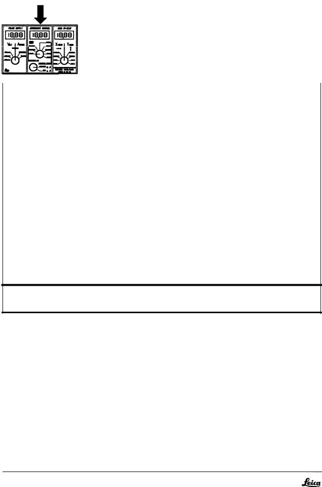
Lamp control
Signal |
Action |
|
|
Reading |
Reaction |
Possible fault |
|
|
|
|
|
|
|
||
LAMP REF |
Adjust lamp to min./max |
0.3V / 5V |
Voltage ok |
Microscope |
|
||
|
brightness |
|
+-5% |
|
(Lamp Control, |
|
|
|
|
|
|
|
|
Wiring) |
|
|
|
|
|
|
|
|
|
|
Separate |
microscope |
|
|
|
|
|
|
from the |
testbox, |
0.3V / 5V |
Voltage ok |
Microscope |
|
|
|
adjust lamp to min./max |
|
|||||
|
brightness |
+-5% |
|
|
|
||
|
|
|
|
|
|
|
|
|
Bridge |
swingarm with |
|
|
|
|
|
|
service |
cable, |
0.3V / 5V |
Voltage ok |
Swingarm cable |
|
|
|
adjust lamp to min./max |
|
|||||
|
brightness |
+-5% |
|
|
|
||
|
|
|
|
|
Voltage not ok |
Control unit |
|
Important: Adjust Iamp again to minimal brightness!
4-7
M695 Fault finding |
Service manual M695 |
09/93 3077-HWE |
Doc code 636 718 |
|
|
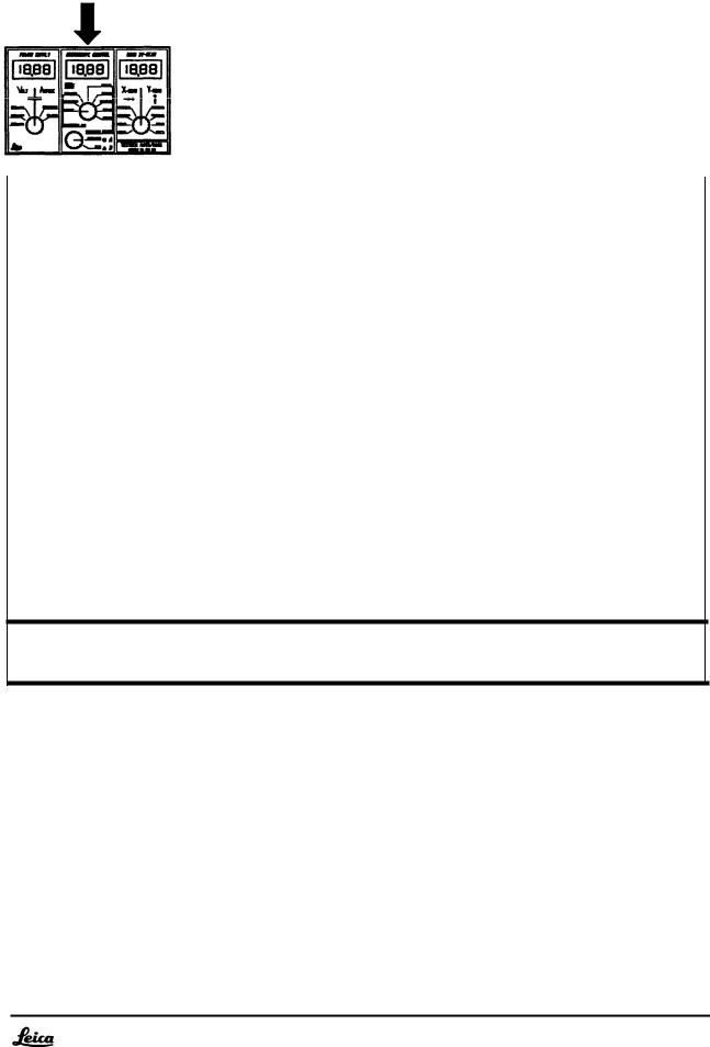
Zoom control
|
Action |
|
|
Heading |
Reaction |
|
Possible fault |
|
|
|
|
|
|
||
ZOOM SPEED Set min. zoom speed |
1.84 ... 2.34V |
|
|
|
|||
|
Set max. zoom speed |
5V +-5% |
|
|
|
||
ZOOM UP |
|
|
>4.75V |
|
|
|
|
|
/footswitch |
|
Voltages ok, but |
Microscope |
|||
|
|
|
|
|
|||
|
non-actuated |
|
<0.2V |
reacts incorrect |
(Logic board. |
||
|
|
|
|
|
|
|
Zoom servo, |
|
|
|
|
|
|
|
wiring) |
ZOOM DN |
|
|
>4.75v |
|
|
|
|
|
/footswitch |
|
|
|
|
||
|
non-actuated |
|
<0.2v |
|
|
|
|
|
Separate microscope |
see above |
Voltages |
ok |
Microscope |
||
|
from the testbox and |
||||||
|
check |
signals |
|
|
|
|
(short circuit on |
|
|
|
|
|
|
|
Zoom servo or |
|
|
|
|
|
|
|
wiring) |
|
Bridge |
swingarm |
with |
|
|
|
|
|
servicecable and |
verify |
see above |
Voltages |
ok |
Swingarm cable |
|
|
signals |
|
|
|
|
|
|
|
|
|
|
|
Voltages not ok |
Control unit |
|
|
|
|
|
|
|
|
|
4-8
Service manual M695 |
M695 Fault finding |
|
Doc code 636 718 |
09/93 3077-HWE |
|
|
|
|
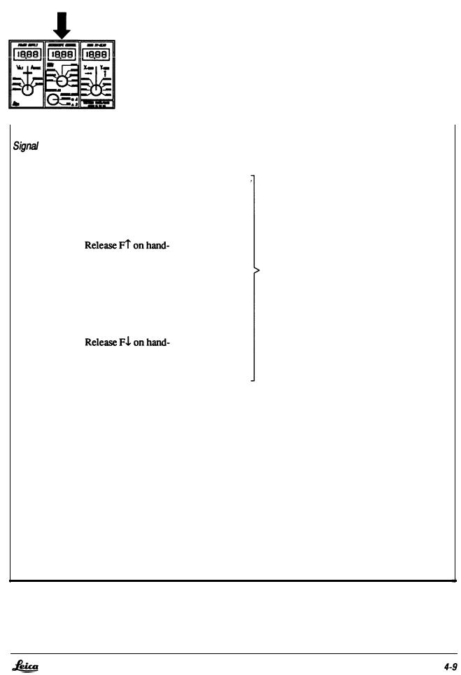
Focus control
Select microscope side A or B:
•Select A or B, depending on which side the zoom works incorrect
•Select A if the fault appeares on both sides, A and B.
|
Action |
Reading |
Reaction |
Possible fault |
||
|
|
|
|
|
|
|
FOCUS SPEED set min. focus speed |
|
|
|
|||
1.25 . . . 1.27V |
|
|
|
|
||
|
set max. focus speed |
5v +-5% |
|
|
|
|
FOCUS UP |
|
|
|
|
|
|
|
/footswitch |
>4.75V |
|
|
Voltage ok, but |
Microscope |
|
|
<0.2V |
|
|
||
|
non-actuated |
|
|
reacts incorrect |
(Focus servo, |
|
|
|
|
|
|
|
wiring) |
FOCUS DN |
|
|
|
|
|
|
|
/footswitch |
>4.75V |
|
|
|
|
|
non-actuated |
<0.2V |
|
|
|
|
|
|
|
|
|||
|
|
|
|
|
|
|
|
Separate microscope |
see above |
|
|
||
|
from the testbox and |
Voltages ok |
Microscope |
|||
|
check signals |
|
|
|
|
(short circuit on |
|
|
|
|
|
|
Focus servo or |
|
|
|
|
|
|
wiring) |
|
|
|
|
|
|
|
|
Bridge swingarm with |
|
|
|
|
|
|
servicecable and verify |
see above |
Voltages ok |
Swingarm- |
||
|
signals |
|
|
|
|
cable |
Voltages not ok |
Control unit |

M695 Fault finding |
Service manual M695 |
09/93 3077-HWE |
Doc code 636 718 |
|
|
4-10

Service manual M695 |
Description control unit MEL64/65 |
Doc code 636 718 |
09/93 3077-HWE |
|
|
Description of functions
MEL64/65 control unit
Chapter |
Page |
|
Introduction |
5-1 |
|
Power |
supply |
5-3 |
Lamp |
control |
5-9 |
Zoom |
control |
5-11 |
Focus |
control |
5-15 |

Service manual M695 |
Description of control unit MEL64/65 |
Doc code 636 718 |
09/93 3077-HWE |
|
|
Description of functions
MEL64/65 control unit
The description is subdivIded for the main groups:
•Control unit MEL64/65 - Section 5
•Swingarm MSV136/137 - Section 6
•M695 microscope - Section 7
The control circuits for zoom, focusing and XY-gear
are located partly in the control unit and partly in the microscope itself. Their functions are described in the following sections 5 and 7.
The swingarm cable
is the electrical link between the control unit and the microscope, and is therefore the ideal place to start looking for faults at the level of the main groups.
The test box is introduced between the swingarm and the microscope. It can be used to study the supply voltages, control signals and control levels, all of which are transmitted through the swingarm cable. Section 6 includes a list of these signals.
5-1
 Loading...