


 Loading...
Leica Geosystems GS20
Field Guide
Version 1.1
English

Leica Geosystems GS20 |
Symbols Used in This Manual |
Congratulations on your purchase of a new Leica Geosystems System GS20.
To use the equipment in the permitted manner, please refer to the detailed safety instructions in the User Manual.
© 2004 Leica Geosystems AG Heerbrugg, ® All rights reserved.
Symbols used in this manual have the following meanings:
WARNING.
Indicates a potentially hazardous situation or an unintended use which, if not avoided, could result in death or serious injury.
)Important paragraphs which must be adhered to in practice as they enable the product to be used in a technically correct and efficient manner
Tip: Indicates useful information that may help you execute a task.
Remember: These paragraphs contain summarized information or important tips.
Leica Geosystems GS20 Field Guide-1.1.0en |
2 |
|

View of chapters
1. |
Basic Operation ................................................................. |
11 |
2. |
Data Collection................................................................... |
21 |
3. |
Data Management .............................................................. |
35 |
4. |
Navigation........................................................................... |
43 |
5. |
Job Management................................................................ |
47 |
6. |
Codelist Management........................................................ |
53 |
7. |
Applications ....................................................................... |
55 |
8. |
Utilities ................................................................................ |
61 |
9. |
Setup ................................................................................... |
63 |
10. |
Status .................................................................................. |
93 |
11. |
Glossary.............................................................................. |
95 |
12. |
Index.................................................................................... |
99 |
Leica Geosystems GS20 Field Guide-1.1.0en |
3 |
View of chapters |
|
|
|

Introduction
The Leica Geosystems GS20
The Leica Geosystems GS20 PDM was conceived to provide the GIS community with a GPS data collection device that combines the simplicity of a recreational GPS handheld with the power and flexibility of a professional grade mapping system. The Leica Geosystems GS20 represents a true turnkey GPS/GIS mapping solution by integrating the GPS receiver and antenna within the chassis of handheld data collector. Add to this the built-in efficiency of Bluetooth wireless technology and you only need add power and sky; the rest is up to you.
Philosophy of Operation
•Data Collection is used for the initial recording and attribution of points, lines, and areas.
•Data Management is used for the update of attribution and geometry of an object; including relocation and continuation of existing geometry
•Navigation is only used for the purpose of finding a known location. Any update to the navigated object must be done in Data Management.
•Utilities contains File Browser, Firmware Update and Sensor Transfer
•Setup allows the user to configure software operation settings such as GPS controls, Data Collection Quality Control, external Interfaces, and Units and Formats, and Languages.
•Status provide the user with information related to GPS, external interfaces and the condition of hardware and software.
Leica Geosystems GS20 Field Guide-1.1.0en |
4 |
Introduction |

Registration
Congratulations on your purchase of the Leica Geosystems GS20 Professional Data Mapper.
To ensure premium support and service of your new GS20, please take the time to fill out and mail the attached Registration Card.
Customer/Business Name Primary Contact Address
City, State (Province), Country Email and Telephone No.
Leica Geosystems GS20 Serial Number *Firmware Version Accessories Purchased Accessory Serial Numbers Who was your Leica Dealer?
How was your out of the box experience?
* Firmware version can be located on the startup screen, or by accessing the Hardware Screen in Status.
Leica Geosystems GS20 Field Guide-1.1.0en |
5 |
Registration |
|
|
|

Company stamp, additional notes/information:
Leica dealer:
Leica Geosystems GS20 Field Guide-1.1.0en |
6 |
Registration |

Table of Contents
1. Basic Operation............................................ |
11 |
||
1.1 |
Batteries and Charging ............................... |
11 |
|
|
1.1.1 |
Calibrating the Battery .............................. |
11 |
1.2 |
Powering On the Unit .................................. |
12 |
|
1.3 |
Icons |
............................................................ |
12 |
|
1.3.1 |
Accuracy Indicator .................................... |
12 |
|
1.3.2 Stop and Go Indicators ............................. |
13 |
|
|
1.3.3 |
Satellite Indicator ...................................... |
13 |
|
1.3.4 |
Differential Corrections ............................. |
13 |
|
1.3.5 |
Memory Card Status ................................. |
13 |
|
1.3.6 Battery and Time Indicators ...................... |
13 |
|
1.4 |
Button Functions ......................................... |
14 |
|
|
1.4.1 |
Alpha Numeric Keys ................................. |
14 |
|
1.4.2 |
Power Key ................................................ |
14 |
|
1.4.3 |
Enter and Escape ..................................... |
15 |
|
1.4.4 |
Cursor Keys .............................................. |
15 |
|
1.4.5 |
Menu Button ............................................. |
15 |
|
1.4.6 |
The Main Menu ......................................... |
16 |
|
1.4.7 |
Paging ....................................................... |
16 |
1.5 |
Software User Interface .............................. |
17 |
|
|
1.5.1 |
Map Views ................................................ |
17 |
|
1.5.2 |
GPS Symbol and Zoom Controls .............. |
18 |
|
1.5.3 |
Context Menus .......................................... |
18 |
|
1.5.4 |
Tables and Filtering .................................. |
19 |
|
|
1.5.5 |
Filtering ..................................................... |
19 |
|
|
1.5.5.1 |
Map Filters ................................................ |
19 |
|
|
1.5.5.2 |
Table Filters .............................................. |
20 |
|
2. Data Collection ............................................. |
21 |
|||
2.1 |
Job Management ........................................ |
21 |
||
2.2 Background Files in the GS20 .................... |
22 |
|||
|
2.2.1 |
Overview ................................................... |
22 |
|
|
2.2.2 |
Adding Background Files to a GS20 Job .. |
22 |
|
|
2.2.3 |
Creating a Background File in |
|
|
|
|
GIS DataPRO ........................................... |
23 |
|
|
2.2.4 Transferring a background File ................. |
23 |
||
|
2.2.5 |
Viewing the Map ....................................... |
24 |
|
|
2.2.6 |
Turning off the background in the Map |
|
|
|
|
Display ...................................................... |
24 |
|
2.3 |
Code Management ...................................... |
25 |
||
|
2.3.1 |
Creating Codelists .................................... |
25 |
|
|
2.3.2 Using the Codelist Manager ..................... |
26 |
||
|
2.3.3 Steps for codelist creation ........................ |
26 |
||
|
2.3.3.1 Step 1: Creating a new codelist in |
|
||
|
|
|
GIS Data Pro ............................................ |
27 |
|
2.3.3.2 |
Step 2: Creating Codes in GIS DataPRO .27 |
||
|
2.3.3.3 Step 3: Creating Attributes ........................ |
28 |
||
Leica GS20 Field Guide-1.1.0en |
7 |
Table of Contents |
|
|
|
2.3.3.4 Step 4: Display Attributes: Attaching Map |
|
|
|
Symbology ............................................... |
29 |
2.3.3.5 Step 5: Transferring Codelist to the |
|
|
|
Sensor ...................................................... |
29 |
2.4 The Codelist and Occupation ...................... |
30 |
|
2.4.1 |
The Job Codelist ....................................... |
30 |
2.4.2 |
Attribution .................................................. |
30 |
2.4.3 |
Point Collection ......................................... |
30 |
2.4.3.1 Point Offsets ............................................. |
31 |
|
2.4.4 Line and Area Collection ........................... |
32 |
|
2.4.5 |
Modes of Collection .................................. |
33 |
3. Data Management......................................... |
35 |
|
3.1 Philosophy of Feature Selection ................. |
35 |
|
3.1.1 Options with Nothing Selected .................. |
35 |
|
3.1.2 Options with a Feature Selected ............... |
35 |
|
3.1.3 Options with a Node Selected .................. |
36 |
|
3.2 Selecting a Feature ..................................... |
36 |
|
3.2.1 |
Feature Management ............................... |
36 |
3.2.1.1 Table Filtering .......................................... |
37 |
|
3.2.2 Selecting a Node or “Vertex” .................... |
37 |
|
3.2.2.1 Node Management ................................... |
37 |
|
3.2.3 |
Feature Submenu ..................................... |
37 |
3.2.4 |
Node Submenu ......................................... |
38 |
3.2.4.1 Re-Occupying Nodes ............................... |
38 |
|
3.2.4.2 Copying and Pasting Nodes ..................... |
39 |
|
3.2.4.3 Inserting, Appending, and Prepending in |
|
|
|
Existing Lines and Areas .......................... |
39 |
3.3 Using the Geographic Clipboard ................. |
40 |
|
3.3.1 |
Purpose of the Geographic Clipboard ...... |
40 |
3.3.2 |
Flow of use (Sharing a common node |
|
|
between blocks) ........................................ |
41 |
3.3.3 |
Creating Point Topology ........................... |
42 |
4. Navigation..................................................... |
43 |
|
4.1 |
The Navigation Screen ................................ |
44 |
4.2 |
Waypoint Selection and Management ........ |
45 |
4.3 |
Creating a new Waypoint feature ................ |
45 |
4.4 |
Updating a Navigated Feature .................... |
46 |
5. Job Management.......................................... |
47 |
|
5.1 Coordinate Systems .................................... |
48 |
|
5.1.1 |
Introduction ............................................... |
48 |
5.1.2 |
Overview ................................................... |
49 |
5.1.3 Attaching a Coordinate System ................ |
49 |
|
5.1.4 |
Field File ................................................... |
50 |
6. Codelist Management .................................. |
53 |
|
6.1 |
Creating a New Codelist ............................. |
53 |
6.2 |
Creating a New Code .................................. |
54 |
|
6.2.1 Creating a New Attribute ........................... |
54 |
Leica GS20 Field Guide-1.1.0en |
8 |
Table of Contents |
7. Applications.................................................. |
55 |
|
7.1 Cultivated Field Control ............................... |
55 |
|
7.1.1 |
Introduction ............................................... |
55 |
7.1.2 |
Setup ........................................................ |
55 |
7.1.3 |
Using the Program .................................... |
57 |
8. |
Utilities .......................................................... |
|
61 |
|
8.1 File Browser ................................................ |
61 |
|
|
8.1.1 |
Browser Controls ...................................... |
61 |
|
8.1.2 |
Context Menu ........................................... |
61 |
|
8.1.3 |
Firmware Update ...................................... |
62 |
|
8.1.4 |
Sensor Transfer ........................................ |
62 |
|
8.1.5 |
Clear System Memory .............................. |
62 |
9. |
Setup ............................................................. |
|
63 |
9.1Selecting, Modifying and Creating
|
Configurations ............................................. |
63 |
|
|
9.1.1 |
Selecting ................................................... |
63 |
|
9.1.2 |
Modifying .................................................. |
63 |
|
9.1.3 |
Creating .................................................... |
63 |
9.2 |
Tree Directory Navigation ........................... |
64 |
|
9.3 |
Hardware Management ............................... |
64 |
|
|
9.3.1 |
Hardware .................................................. |
64 |
|
9.3.2 |
Contrast .................................................... |
65 |
|
9.3.3 |
Wireless (Bluetooth Connectivity) ............. |
65 |
|
9.3.3.1 Selecting a Wireless Device .................... |
65 |
|
|
9.3.4 Clearing a Selected Device ...................... |
66 |
|
|
9.3.5 |
Real - Time Corrections with a Mobile |
|
|
|
Phone ....................................................... |
66 |
|
9.3.6 Linking with the Bluetooth ......................... |
67 |
|
|
9.3.7 |
Configuring your Device ........................... |
67 |
|
9.3.8 |
Modifying your Configuration .................... |
68 |
|
9.3.8.1 Status Indication ....................................... |
68 |
|
|
9.3.9 Connecting to the Station ......................... |
68 |
|
9.4 |
ID Template Management ........................... |
69 |
|
|
9.4.1 |
Creating an ID Template ........................... |
69 |
|
9.4.2 Modifying an Existing Template ................ |
69 |
|
9.5 |
Device Manager .......................................... |
70 |
|
|
9.5.1 |
Creating a New Device ............................. |
70 |
|
9.5.2 Modifying an Existing Device .................... |
70 |
|
9.6 |
GPS |
............................................................. |
70 |
|
9.6.1 |
Tracking .................................................... |
70 |
|
9.6.2 .................................... |
Minimum Satellites |
71 |
|
9.6.3 ........................................... |
Antenna Type |
71 |
|
9.6.4 ..................................................... |
Logging |
71 |
|
9.6.5 ............................................... |
Initialization |
72 |
9.7 |
Data ............................................Collection |
72 |
|
|
9.7.1 .......................................... |
Quality Monitor |
72 |
9.8 |
Interfaces .................................................... |
73 |
|
|
9.8.1 ................................................. |
Real - Time |
73 |
|
9.8.2 ................................. |
GS20 Phase Wizard |
74 |
|
9.8.2.1 ...................................................Overview |
74 |
|
Leica GS20 Field Guide-1.1.0en |
9 |
Table of Contents |
|
|
|
9.8.2.2 |
Static Phase ............................................. |
75 |
9.8.2.3 |
Kinematic Phase ...................................... |
75 |
9.8.2.4 |
The Interface ............................................ |
75 |
9.8.2.5 Collecting Static points, including kinematic |
||
|
points of initialization ................................ |
76 |
9.8.3 WAAS and EGNOS .................................. |
77 |
|
9.8.3.1 Understanding the WAAS Corrections ..... |
78 |
|
9.8.3.2 Changes to the Real-Time Screen ........... |
79 |
|
9.8.4 Connecting to WoRCS Beacon ................ |
79 |
|
9.8.4.1 Powering on the WoRCS ......................... |
80 |
|
9.8.4.2 Checking the Bluetooth Link .................... |
80 |
|
9.8.4.3 Checking the WoRCS Real-Time Link ..... |
81 |
|
9.8.4.4 |
WoRCS Real-Time Beacon ..................... |
81 |
9.8.5 Connecting to WoRCS Real-Time Satellite |
||
(RTS) ........................................................ |
82 |
|
9.8.5.1 Powering on the WoRCS ......................... |
83 |
|
9.8.5.2 Checking the Bluetooth Link .................... |
83 |
|
9.8.5.3 Checking the WoRCS Real-Time Link ..... |
85 |
|
9.8.5.4 |
WoRCS RTS ............................................ |
85 |
9.8.6 Offset Devices .......................................... |
86 |
|
9.8.6.1 Configuration of the GS20. ....................... |
86 |
|
9.8.6.2 Overview of the basic methodologies of |
|
|
|
point offset data collection. ....................... |
88 |
9.8.6.3 Explanation of individual point offset data |
|
|
|
collection methodologies. ......................... |
89 |
9.8.7 ASCII Input ............................................... |
91 |
|
9.9 Units and Formats ....................................... |
92 |
|
9.9.1 Units of Measure ....................................... |
92 |
|
9.9.2 |
Language .................................................. |
92 |
9.9.3 |
Formats ..................................................... |
92 |
10.Status............................................................ |
93 |
|
10.1 |
GPS ............................................................. |
93 |
|
10.1.1Position ..................................................... |
93 |
|
10.1.2Satellite Information .................................. |
93 |
|
10.1.3Satellite View ............................................ |
94 |
10.2 |
Interfaces .................................................... |
94 |
|
10.2.1Real-Time ................................................. |
94 |
|
10.2.1.1 RTB Coast Guard Beacon ........................ |
94 |
10.3 |
Hardware ..................................................... |
94 |
11.Glossary ....................................................... |
95 |
|
12.Index ............................................................. |
99 |
|
Leica GS20 Field Guide-1.1.0en |
10 |
Table of Contents |
1. Basic Operation
1.1Batteries and Charging
Leica Geosystems GEB90, 7.2 volt, 2100 mAh Lithium-Ion batteries must be used to power the Leica GS20 and WoRCS equipment. Charge only with the Leica Geosystems battery charger provided in the system.
WARNING:The battery chargers are intended for indoor use only. Use a battery charger in a dry room only, never
outdoors. Charge batteries only at an ambient temperature between 10° C and 30° C (50° F to 86° F). We recommend a temperature of 0° C to +20° C (32° F to 68° F) for storing the batteries.
1.1.1Calibrating the Battery
The Leica Geosystems GEB90 battery uses a microprocessor to accurately monitor the battery status. To calibrate the battery microprocessor, allow the Leica Geosystems GS20 to rundown and automatically power off.
)The Leica Geosystems GEB90 battery can be referenced and ordered by Leica part number 724117. The Leica Geosystems GKL24 Dual Bay Battery Charger can be referenced and ordered by Leica part number 731771.
)Use only the Leica Geosystems batteries, chargers, and accessories, or accessories recommended by Leica Geosystems.
Leica GS20 Field Guide-1.1.0en |
11 |
Basic Operation |
|
|
|

1.2Powering On the Unit
Press and release the Power Button located on lower left of the keyboard. The unit will reply with an audible tone, then proceed to a splash screen and then to the Main Menu.
Remember: Although the unit can power on without the flash card, most functionality will not be available.
1.3Icons
The Icon area is displayed to provide the user with current information about the GPS and hardware.
1.3.1 |
|
|
|
|
|
|
|
|
|
|
|
|
|
1.3.6 |
|
|
|
|
|
|
|
||||||||
|
1.3.2 |
|
|
|
|
|
|
|
|
|
1.3.5 |
|
||
|
|
|
|
|
|
|
|
|
|
|
|
|||
|
|
|
|
|
|
|
|
|
|
|
|
|
||
|
|
1.3.3 |
|
|
|
1.3.4 |
|
|
||||||
|
|
|
|
|
|
|
||||||||
Figure 1-1: Accuracy Indicator
1.3.1Accuracy Indicator
The accuracy indicator is displayed once a solution is calculated. The open sphere indicates that an autonomous position has been determined and the bullseye target indicates a DGPS solution. Additionally information provided in the text include horizontal and vertical qualities, as well as PDOP.
Leica GS20 Field Guide-1.1.0en |
12 |
Basic Operation |
1.3.2Stop and Go Indicators
When a static position is located, such as a point or a node (in a line or area), the stop and go indicator is displayed as a tripod. Once the icon returns to the walkingman, the user can proceed to the next collection point.
1.3.3Satellite Indicator
The satellite indicator provides text based information including the satellite tracking angle, the number of satellites visible (according to the almanac) and the number of satellites currently tracked.
(Satellites Tracked / Satellites Visible)
1.3.4Differential Corrections
When differential corrections are received and interpreted, the differential icon appears. If the correction is lost after 1/3 of the selected age (see 9.8.1 "Real-Time"), an exclamation point will appear in the lower left hand corner of the window. If it is still absent after 2/3 of the selected age, an additional exclamation mark will appear. If corrections are lost beyond the selected age, a third exclamation will appear and the icon will then disappear.
1.3.5Memory Card Status
The memory card status icon provides a graphical representation of the percentage of the compact flash used.
1.3.6Battery and Time Indicators
The battery and time indicators provide information about the current status of the onboard battery and the current time obtained by satellites.
•Because the Battery indicator is based on a microprocessor in the Lithium Ion battery, only the onboard battery status can be provided in percentages.
•Because the Leica Geosystems GS20 does not rely on internal batteries for clock function, time is only displayed when 1 or more satellites is tracked.
Leica GS20 Field Guide-1.1.0en |
13 |
Basic Operation |
|
|
|

1.4Button Functions
1.4.1Alpha Numeric Keys
Keys 1-9 represent the alpha numeric entry keys of the GS20. Similar to a cellular phone, buttons 2-9 contain alpha characters; by pressing the key continuously, all characters on that key will be scrolled. The selection of a character can be made by either selecting a different key, or waiting for the 2 second time-out. Special characters can be found on the decimal key on the lower right of the keyboard.
1.4.2Power Key
To power the unit on, the power key needs only to be pressed and released. The unit will then respond with an audible tone, followed by the splash screen.
)Time to splash screen may depend on compact flash size and the amount of data on disk.
While in operation, the backlight can be turned on with a button press of less than 3 seconds.
If the power key is depressed and held for three seconds, the unit will power down and give a message confirming the power down and saving of data.
Figure 1-2: Leica GS20 Keypad
Remember: Depressing and holding the key acts like multiple key presses.
Multiple functions: Keys 3 and 9 have been provided with additional functionality. In a map display, 3 and 9 function as zoom keys; in a table, 3 and 9 function as page up and page down.
Leica GS20 Field Guide-1.1.0en |
14 |
Basic Operation |
Table 1-1: Overloaded Button Functions
|
Map |
Table |
|
|
|
|
|
|
3 Down |
Zoom In |
Page Down |
|
|
|
9 Up |
Zoom Out |
Page Up |
|
|
|
1.4.3Enter and Escape
Similar to standard Windows’ controls, the Enter key is used to either accept a choice or advance an action. The Escape key functions both as a back key, to escape from a current screen; as well as a backspace in edit fields.
1.4.4Cursor Keys
Cursor keys are found on the face and the side of the unit; the side cursors function exactly the same as the up and down cursor on the face. If held down, the cursor key will automatically speed up, such as in the map display, table, or edit field. Because the cursor key is so integral to control and entry, its functions vary in different controls.
1.Menus: Left and Right function as home and end.
2.Edit Fields: Up and Down function as home and end.
3.Check Boxes and Radio Buttons: Left/Right toggle makes a field selection.
4.Combo Box and Spin Controls: Left and Right scroll selections.
5.Map: Controls the cursor
1.4.5Menu Button
The Menu key is the prime key in the Leica Geosystems GS20 user interface. Not only can Menu bring you quickly back to the Main Menu to load the paging queue and select new application, it also opens the context menu which contains all of the high level controls for the unit.
Leica GS20 Field Guide-1.1.0en |
15 |
Basic Operation |
|
|
|
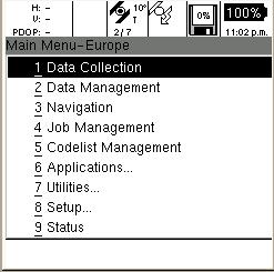
1.4.6The Main Menu
The Main Menu is the base level of the Leica Geosystems GS20 user interface. The Main Menu can be quickly accessed from an application by double clicking the Menu button. By returning to the Main Menu in an open application, it is possible to run several application simultaneously; this is referred to as the paging function.
1.4.7Paging
Because it is often necessary to access several applications at once (e.g. data collection, navigation, satellite view, etc.) Leica Geosystems has created the Power Paging function.
Power Paging allows the user to quickly and easily flip through running applications in the order they were opened. To place an application in the paging queue, simply open the application from the Main Menu. To add an additional application to the queue, double click Menu to return to the Main Menu, then open a new application. The paging button will then page through the open applications. To remove an application from the page, simply Escape from the application to the Main Menu.
Figure 1-3: GS20 Main Menu
Leica GS20 Field Guide-1.1.0en |
16 |
Basic Operation |
1.5Software User Interface
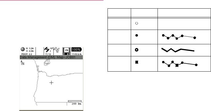
1.5.1Map Views
The map view is the common interface on which all main applications are built. Data Collection, Data Management and Navigation all contain a map interface that has similar controls and are continuously updated, but have independent settings. Zooms, filtering, selection, and autopan GPS are all unique to each applications mapview.
Table 1-2: Mapview Legend
Points |
Lines and Areas |
Normal
Selected
Filtered
Selected
Node
Normal: Standard features in Mapview Selected: The currently active feature selection Filtered: Display of features in a current table
Figure 1-4: Mapview (Selected and Filtered)
Leica GS20 Field Guide-1.1.0en |
17 |
Basic Operation |
|
|
|
1.5.2GPS Symbol and Zoom Controls
By default, an open mapping screen zooms to the full extent of data in a job; however if no data exists, the map will be centered on the GPS location (scaled to 1:20m) awaiting collected data.
The map submenu contains zoom controls for
•Zoom In, Zoom Out, Zoom To Full Extents
•Center Cursor, Center GPS, Center Selected
•Autopan GPS
Remember: “3” and “9” function as zoom controls !
Remember: The mapview is only capable of displaying 12,000 nodes, being points or line/area verticies. A warning will be issued at 9500 nodes, that the map will be discontinued. A final warning will be issued before the map display is turned off.
Tip: To minimize nodes in a job; consider streaming lines and areas by distance or at a slower rate. An 8 hour constant collection at a 5 second interval only produces 5760 nodes.
)The map display can be turned off in the Job Management Screen.
1.5.3Context Menus
The context menu in the Leica Geosystems GS20 functions similarly to a Windows’ context menu, however the right mouse click is replaced with the Menu
button. When the Menu button is depressed, a list of choices will be displayed based on the application and the actions taken.
•Choices in the context menu can either be selected using the cursor arrows (Left and Right being home and end) or directly accessed via the number keys.
•To simplify submenus appear where common groupings exist such as map control functions. The submenu is denoted with a right arrow and is accessed via enter or the number key. In some instances, sub-submenus exist.
Leica GS20 Field Guide-1.1.0en |
18 |
Basic Operation |
1.5.4Tables and Filtering
Tables are used to display multiple attribute data that cannot be directly edited. The table can be navigated by the cursor keys (left and right being home and end) as well as the overload keys 3 Page Down and 9 Page Up.
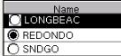
Two main types of tabular data found in the GS20 are selectable and informative.
•Selectable fields allow the user to make a selection such as choosing a Job or Codelist, and are usually identified by a radio button (selectable circle). Additional options, such as New, Delete, etc. usually exist in the context menu.
Figure 1-5: Selectable Table
•Informative fields allow the user to view and manipulate information about the tabled object.
1.5.5Filtering
In order to provide power and flexibility to the user, the Leica Geosystems GS20 maintains separate filters for individual tables and maps.
1.5.5.1 Map Filters
Map filters provide the user with the ability to hide or display data in the map.
Map filters allow the user to discriminate data based on
•Feature Code (Layer name)
•Feature Name (Feature ID)
•Feature Type (Point, Line, or Area)
•Time of collection
•Waypoint Status (Flag as Waypoint (i.e. to be navigated to)
or Visited)
Similarly data can be filtered in a table for selection, edits, clipboard function or changing the Waypoint status.
Leica GS20 Field Guide-1.1.0en |
19 |
Basic Operation |
|
|
|
1.5.5.2 Table Filters
Table filters allow the user to search for data based upon the same criteria as listed above in map filters.
Once a table is filtered, the user can select from the filtered table, or view the selected filters in the map view via the context menu choice Table Features.
)This differs from map filtering in that the data remains displayed, but appears highlighted.
Leica GS20 Field Guide-1.1.0en |
20 |
Basic Operation |
2. Data Collection
2.1Job Management
When Data Collection is opened, if no job is currently selected, the user will be prompted to either “Open” an existing job or create a “New” job to continue. If a new or empty job is selected, the unit will prompt the user to attach a codelist; otherwise the program will proceed to the Data Collection map.
|
Figure 2-2: Job Management Screenflow |
Tip: When you create a new job, you have the option of |
|
|
attaching a Coordinate System and Geoid file with |
Figure 2-1: Job Management Screenflow |
creation of the job. |
Tip: |
See 5. "Job Management" for more info |
Leica GS20 Field Guide-1.1.0en |
21 |
Data Collection |
|
|
|
2.2Background Files in the GS20
Often it is important for a user to see the location of they’re current position and those Features they have collected within a larger context. However, it is not always necessary or even beneficial to have that data selectable. With the ability to create vector background data, the GS20 can now:
•Attach larger vector reference files
•Use the same vector reference file for multiple jobs
•Reference multiple files to a job
•Reference previously collected jobs in an open job
•Only re-import collected or updated data
2.2.1Overview
GS20 background files are graphic files that can be created in GIS DataPRO, and are automatically created when job data is collected in the GS20. The graphic file contains the file extension qtr, which stands for quadtree; a method of spatially indexing vector data. When a job is created in the GS20, a graphic file of that same name is also created. From job management, a background screen can be accessed, allowing the user to reference other “background” graphical data to the job. Background graphic files are for visual reference only, and are not selectable.
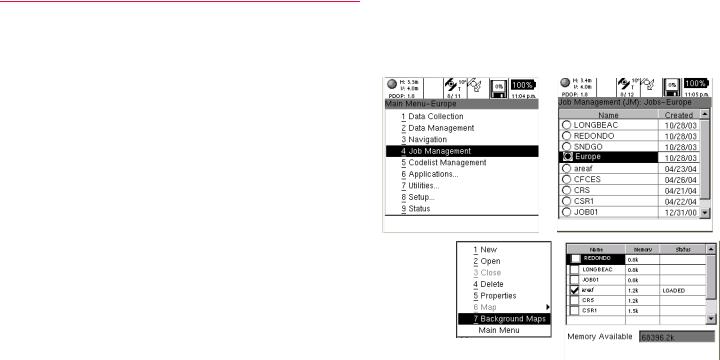
2.2.2Adding Background Files to a GS20 Job
To add a background Map, enter Job management, highlight a selected job, and select “Background Maps” from the context menu.
Figure 2-3: Background Maps
Leica GS20 Field Guide-1.1.0en |
22 |
Data Collection |
A status of available memory will be available to provide information on how much information can be attached to a job. Memory used in background files will affect the amount of map data that can be collected, so be conservative in your estimates.
A successful attachment will be shown in the Status column and Memory Available will be recalculated.
2.2.3Creating a Background File in GIS DataPRO
In order to create a graphic file in GIS DataPRO, it will be necessary to first import the data into the GIS DataPRO database.
Data that is added to GIS DataPRO with the +, or add shapes cannot be converted into a graphics file.
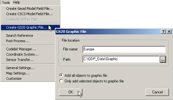
To create the Graphics file, select “Create GS20 Graphic File” from the Tools pull-down menu.
A dialog will prompt for a filename and path, with the default being active. The user can select to create a background from all data, or only selected objects.
Figure 2-4: Creating a background
2.2.4Transferring a background File
To transfer a graphic file, open Tools / Sensor Transfer. Right click on Sensors, and Add a Sensor. Under My Computer, browse to the location of the Graphics file.
Right Click on the Graphic File and send to your connected Device.
Leica GS20 Field Guide-1.1.0en |
23 |
Data Collection |
|
|
|
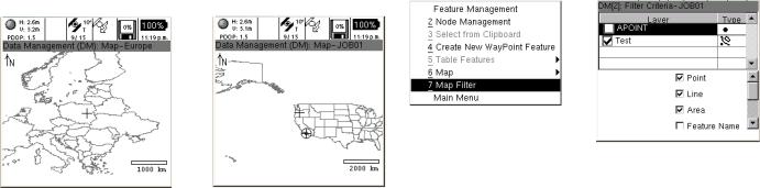
2.2.5Viewing the Map
If all has gone according to plan, the graphic file will be attached to the current job, and will be displayed in Map View applications. Because the memory used by the graphic files are not recovered during use, it will be necessary to reboot to reclaim lost space once a background is detached from a job.
2.2.6Turning off the background in the Map Display
Similar to the Filtering ability of layers and data types in a Map View, Background files can be turned on and off. To turn off a Map view, select the Map Filter from the Map context menu, and press enter on the layer with the new Background Icon.
Figure 2-6: Turning off the background
Figure 2-5: Viewing the Map
Leica GS20 Field Guide-1.1.0en |
24 |
Data Collection |

2.3Code Management
Because the Leica Geosystems GS20 is designed for GIS data creation and update, existing feature layer will be used as a code template for each particular job. Additional codelists can be attached to a job via Codelist Manager.
In order to protect database integrity, a consistency check is performed when codelists are attached to a job. If the same code occurs in both the feature table and the codelist, the job feature data will be used.
Codelists can be attached and detached as well as created and modified from the Codelist Manager in the MAIN menu.
2.3.1Creating Codelists
What is a Code? Codes are used to describe objects of the same type. The code in GIS DataPRO is equivalent to the Theme in ArcView 3.2. Each code has it’s own type, with only one type per code: point, line or polygon For example: Tree (Point), Roads(Line), Parcels(Polygon).
A code contains attribute information that may be assigned to the Codes (points, lines or areas) during measurement in the field.
For example: Fire Hydrant (Code): Serial Number and Color (Attributes).
A Codelist contains codes to be collected in a job, and is attached to a job.
A codelist can be created in three ways:
1.Create your own codelist/code.
2.Copy another codelist/code from another project.
3.Import codes from existing shapefile.
Codelists are created in the Codelist Manager in GIS DataPRO.
Leica GS20 Field Guide-1.1.0en |
25 |
Data Collection |
|
|
|
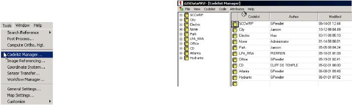
2.3.2Using the Codelist Manager
1. Select Tools from the Main Menu.
2.Select Codelist Manager, this is the interface you will see. Listed below are the steps for codelist creation. We will list them here, and then look at each one in depth.
2.3.3Steps for codelist creation
1.Create a Codelist in GIS DataPRO
2.Create Codes -
Unlimited codes in a codelist
3.Create Attributes -
Maximum 60 Attributes per code
4.Attach Map Symbology to each code in a codelist
5.Save codelist
6.Transfer a Codelist to sensor.
Leica GS20 Field Guide-1.1.0en |
26 |
Data Collection |
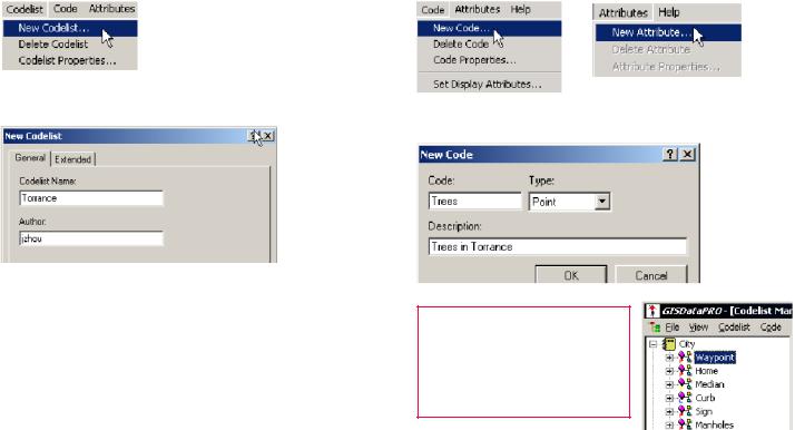
2.3.3.1 Step 1: Creating a new codelist in GIS Data Pro |
2.3.3.2 Step 2: Creating Codes in GIS DataPRO |
1. Click on Codelist and select New Codelist |
1. From the pull down menu choose new code |
2.Type in name of the New Codelist.
3.Click OK.
2. Create a new Code Name and Description
Your new codelist is now created, highlighted and ready to be populated.
)When a codelist is created the first code is always Waypoint and cannot be changed!
Leica GS20 Field Guide-1.1.0en |
27 |
Data Collection |
|
|
|

2.3.3.3 Step 3: Creating Attributes
1.From the Attribute pull down menu choose New Attribute
2.Fill in the attribute name and properties.
3.The attribute Type can be Normal, Mandatory or Fixed
4. The attribute Value can be Text, Real or Integer
5.The attribute Value Region Can be None, Choice List or Range
6.The Default Value can be typed in if None or Range was selected in the Value region. It can be selected if Choice List was used.
Leica GS20 Field Guide-1.1.0en |
28 |
Data Collection |
Facts About Attributes:
1.The Z attribute is reserved and cannot be changed.
2.The Z attribute contains elevation data
3.Maximum 256 characters per Choice List
4.Attribute names must begin with a letter
5.Limit the attribute names to 10 characters
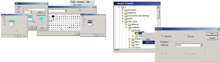
2.3.3.4 Step 4: Display Attributes: Attaching Map Symbology
The display properties are used to display each feature in the GIS DataPRO after data collection.
From the Code pull down, choose “Set Display Attributes. The Codelist may now be saved with map symbology intact.
2.3.3.5 Step 5: Transferring Codelist to the Sensor
1.Open Sensor Transfer
2.Add Sensor
3.Browse to location where codelists are stored (default location: C:\GDP_Data\Codelists)
4.Right click on codelist and select Send Files...
5.In the Send Files... dialog select the codes you would like transferred
6.Select the appropriate COM port and select Codelist from
the File Type Choice
With your codelist now on the sensor, you are ready to attach it to your job and collect GIS Data.
Figure 2-7: Map Symbology
Figure 2-8: Transferring Codelists
Leica GS20 Field Guide-1.1.0en |
29 |
Data Collection |
|
|
|
2.4The Codelist and Occupation
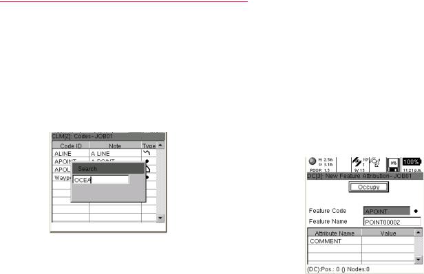
2.4.1The Job Codelist
If a job is new (i.e. does not contain any data), the user will be taken to the code table; otherwise the user is defaulted into a map view. From the mapview, you can enter features via the context menu, or by just pressing Enter. From the code table screen, the code template can be selected by using the cursor or searching with the pop-up dialog (which opens with an alpha numeric key.)
2.4.2Attribution
After a code is selected, press Enter to open the attribution screen. By default the focus is on the Occupy button; however, by using the cursor and Enter key, attribution values can be entered. Additional occupation selections can be accessed via the context menu.
2.4.3Point Collection
Point collection is often as simple as entering attributes, pressing Occupy and Save; however different user defined quality settings can determine how the feature is collected (see Setup/Data Collection.) In addition to direct locations, the user can also choose from a list of point offsets.
Figure 2-9: Data Collection / Job Codelist
Figure 2-10: Attribution / Point Occupation
Leica GS20 Field Guide-1.1.0en |
30 |
Data Collection |
Loading...