


 Loading...
Maintenance & Service Guide
HP Pro 3000 Business PCs
HP Pro 3010 Business PCs
HP Pro 3080 Business PCs
© Copyright 2009 Hewlett-Packard Development Company, L.P. The information contained herein is subject to change without notice.
Microsoft and Windows are trademarks of Microsoft Corporation in the U.S. and other countries.
The only warranties for HP products and services are set forth in the express warranty statements accompanying such products and services. Nothing herein should be construed as constituting an additional warranty. HP shall not be liable for technical or editorial errors or omissions contained herein.
This document contains proprietary information that is protected by copyright. No part of this document may be photocopied, reproduced, or translated to another language without the prior written consent of Hewlett-Packard Company.
Maintenance & Service Guide
HP Pro 3000 Business PCs
HP Pro 3010 Business PCs
HP Pro 3080 Business PCs
First Edition (November 2009)
Document Part Number: 597662-001

About This Book
WARNING! Text set off in this manner indicates that failure to follow directions could result in bodily harm or loss of life.
CAUTION: Text set off in this manner indicates that failure to follow directions could result in damage to equipment or loss of information.
 NOTE: Text set off in this manner provides important supplemental information.
iii
iv About This Book

Table of contents
1 Product Features ............................................................................................................................................ |
1 |
Microtower Models ............................................................................................................................... |
4 |
Serviceability Features ........................................................................................................ |
4 |
Front Panel Components ..................................................................................................... |
4 |
Media Card Reader Components ........................................................................................ |
5 |
Rear Panel Components ..................................................................................................... |
6 |
HP Pro 3000 MT/3080 MT .................................................................................. |
6 |
HP Pro 3010 MT ................................................................................................. |
7 |
Small Form Factor Models ................................................................................................................... |
8 |
Serviceability Features ........................................................................................................ |
8 |
Front Panel Components ..................................................................................................... |
8 |
Rear Panel Components ..................................................................................................... |
9 |
HP Pro 3000 SFF ................................................................................................ |
9 |
HP Pro 3010 SFF .............................................................................................. |
10 |
2 Installing and Customizing the Software .................................................................................................... |
11 |
Installing the Operating System ......................................................................................................... |
11 |
Downloading Microsoft Windows Updates ......................................................................................... |
11 |
Installing or Upgrading Device Drivers (Windows systems) ............................................................... |
12 |
Accessing Disk Image (ISO) Files ...................................................................................................... |
12 |
Protecting the Software ...................................................................................................................... |
12 |
3 Computer Setup (F10) Utility ....................................................................................................................... |
13 |
HP Pro 3000/3080 – Computer Setup (F10) Utility ............................................................................ |
13 |
Using Computer Setup (F10) Utilities ................................................................................ |
13 |
Computer Setup—Main ..................................................................................................... |
15 |
Computer Setup—Advanced ............................................................................................. |
16 |
Computer Setup—Boot ...................................................................................................... |
17 |
Computer Setup—Power ................................................................................................... |
18 |
Computer Setup—PC Health ............................................................................................. |
18 |
Computer Setup—Exit ....................................................................................................... |
19 |
HP Pro 3010 – Computer Setup (F10) Utility ..................................................................................... |
19 |
Using Computer Setup (F10) Utilities ................................................................................ |
19 |
Computer Setup—Main ..................................................................................................... |
20 |
v
Computer Setup—Advanced ............................................................................................. |
21 |
Computer Setup—Power ................................................................................................... |
23 |
Computer Setup—Boot ...................................................................................................... |
23 |
Computer Setup—Exit ....................................................................................................... |
24 |
4 Serial ATA (SATA) Drive Guidelines and Features .................................................................................... |
25 |
SATA Hard Drives .............................................................................................................................. |
25 |
SATA Hard Drive Cables .................................................................................................................... |
25 |
SATA Data Cable .............................................................................................................. |
25 |
SMART ATA Drives ............................................................................................................................ |
26 |
Hard Drive Capacities ........................................................................................................................ |
26 |
5 Identifying the Chassis, Routine Care, and Disassembly Preparation .................................................... |
27 |
Electrostatic Discharge Information .................................................................................................... |
27 |
Generating Static ............................................................................................................... |
27 |
Preventing Electrostatic Damage to Equipment ................................................................ |
28 |
Personal Grounding Methods and Equipment ................................................................... |
28 |
Grounding the Work Area .................................................................................................. |
29 |
Recommended Materials and Equipment .......................................................................... |
29 |
Operating Guidelines .......................................................................................................................... |
30 |
Routine Care ...................................................................................................................................... |
31 |
General Cleaning Safety Precautions ................................................................................ |
31 |
Cleaning the Computer Case ............................................................................................ |
31 |
Cleaning the Keyboard ...................................................................................................... |
31 |
Cleaning the Monitor .......................................................................................................... |
32 |
Cleaning the Mouse ........................................................................................................... |
32 |
Service Considerations ...................................................................................................................... |
32 |
Power Supply Fan ............................................................................................................. |
32 |
Tools and Software Requirements .................................................................................... |
32 |
Screws ............................................................................................................................... |
33 |
Cables and Connectors ..................................................................................................... |
33 |
Hard Drives ........................................................................................................................ |
33 |
Lithium Coin Cell Battery ................................................................................................... |
34 |
6 Removal and Replacement Procedures Microtower (MT) Chassis .......................................................... |
35 |
Preparation for Disassembly .............................................................................................................. |
35 |
Access Panel ...................................................................................................................................... |
36 |
Front Bezel ......................................................................................................................................... |
37 |
Bezel Blanks ....................................................................................................................................... |
38 |
Memory .............................................................................................................................................. |
39 |
DDR3-SDRAM DIMMs ...................................................................................................... |
39 |
Populating DIMM Sockets ................................................................................................. |
40 |
Installing Memory Modules ................................................................................................ |
42 |
vi
Expansion Cards ................................................................................................................................ |
44 |
Cable Management ............................................................................................................................ |
49 |
Cable Connections ............................................................................................................ |
50 |
HP Pro 3000/3080 ............................................................................................. |
50 |
HP Pro 3010 ...................................................................................................... |
51 |
Drives ................................................................................................................................................. |
52 |
Drive Positions ................................................................................................................... |
52 |
Installing Additional Drives ................................................................................................. |
53 |
System Board Drive Connections ..................................................................... |
54 |
Removing an Optical Drive ............................................................................... |
56 |
Installing an Optical Drive into the 5.25-inch Drive Bay .................................... |
57 |
Removing an External 3.5-inch Drive ................................................................ |
58 |
Installing a Drive into the 3.5-inch External Drive Bay ...................................... |
59 |
Removing an Internal 3.5-inch Hard Drive ........................................................ |
60 |
Installing an Internal 3.5-inch Hard Drive .......................................................... |
64 |
Front I/O and USB Panel Housing Assembly ..................................................................................... |
67 |
Power Switch/LED Assembly ............................................................................................................. |
68 |
System Fan ........................................................................................................................................ |
69 |
Heat sink assembly ............................................................................................................................ |
70 |
Processor ........................................................................................................................................... |
71 |
Power Supply ..................................................................................................................................... |
72 |
System Board ..................................................................................................................................... |
74 |
Battery ................................................................................................................................................ |
75 |
Type 1 Battery Holder ........................................................................................................ |
76 |
Type 2 Battery Holder ........................................................................................................ |
77 |
Type 3 Battery Holder ........................................................................................................ |
77 |
Installing a Security Lock .................................................................................................................... |
79 |
HP/Kensington MicroSaver Security Cable Lock ............................................................... |
79 |
Padlock .............................................................................................................................. |
79 |
HP Business PC Security Lock .......................................................................................... |
80 |
Hood Sensor ...................................................................................................................... |
82 |
HP Chassis Security Kit ..................................................................................................... |
83 |
7 Removal and Replacement Procedures Small Form Factor (SFF) Chassis ............................................ |
84 |
Preparation for Disassembly .............................................................................................................. |
84 |
Access Panel ...................................................................................................................................... |
85 |
Front Bezel ......................................................................................................................................... |
86 |
Bezel Blanks ....................................................................................................................................... |
87 |
Memory .............................................................................................................................................. |
88 |
DDR3-SDRAM DIMMs ...................................................................................................... |
88 |
Populating DIMM Sockets ................................................................................................. |
89 |
Installing DIMMs ................................................................................................................ |
91 |
Removing or Installing an Expansion Card ........................................................................................ |
94 |
vii
Cable Management ............................................................................................................................ |
99 |
Cable Connections .......................................................................................................... |
100 |
HP Pro 3000/3080 ........................................................................................... |
100 |
HP Pro 3010 .................................................................................................... |
100 |
Drives ............................................................................................................................................... |
101 |
Drive Positions ................................................................................................................. |
101 |
Installing Additional Drives ............................................................................................... |
102 |
System Board Drive Connectors ..................................................................... |
103 |
Removing an Optical Drive ............................................................................. |
105 |
Installing an Optical Drive into the 5.25-inch Drive Bay .................................. |
106 |
Removing an External 3.5-inch Drive .............................................................. |
108 |
Installing a Drive into the 3.5-inch External Drive Bay .................................... |
110 |
Removing an Internal 3.5-inch Hard Drive ...................................................... |
113 |
Installing an Internal 3.5-inch Hard Drive ........................................................ |
115 |
Plastic Wire/Cable Fastener and Clips ............................................................................................. |
117 |
Front I/O Device ............................................................................................................................... |
119 |
Power Switch Assembly ................................................................................................................... |
120 |
Heatsink ........................................................................................................................................... |
121 |
Processor ......................................................................................................................................... |
122 |
Power Supply ................................................................................................................................... |
123 |
System Board ................................................................................................................................... |
125 |
Battery .............................................................................................................................................. |
126 |
Type 1 Battery Holder ...................................................................................................... |
127 |
Type 2 Battery Holder ...................................................................................................... |
127 |
Type 3 Battery Holder ...................................................................................................... |
128 |
Installing a Security Lock .................................................................................................................. |
129 |
HP/Kensington MicroSaver Security Cable Lock ............................................................. |
129 |
Padlock ............................................................................................................................ |
129 |
HP Business PC Security Lock ........................................................................................ |
130 |
Hood Sensor .................................................................................................................... |
132 |
HP Chassis Security Kit ................................................................................................... |
133 |
Appendix A Connector Pin Assignments .................................................................................................... |
134 |
Ethernet BNC ................................................................................................................................... |
134 |
USB .................................................................................................................................................. |
134 |
Microphone ....................................................................................................................................... |
134 |
Headphone ....................................................................................................................................... |
135 |
Line-in Audio .................................................................................................................................... |
135 |
Line-out Audio .................................................................................................................................. |
135 |
4-Pin Power (for CPU) ...................................................................................................................... |
135 |
Monitor ............................................................................................................................................. |
136 |
24-Pin Power .................................................................................................................................... |
136 |
PCI Express ..................................................................................................................................... |
137 |
viii
PCI Express ..................................................................................................................................... |
138 |
Appendix B Power Cord Set Requirements ................................................................................................ |
139 |
General Requirements ..................................................................................................................... |
139 |
Japanese Power Cord Requirements .............................................................................................. |
139 |
Country-Specific Requirements ........................................................................................................ |
140 |
Appendix C Troubleshooting Without Diagnostics .................................................................................... |
141 |
Safety and Comfort .......................................................................................................................... |
141 |
Before You Call for Technical Support ............................................................................................. |
141 |
Helpful Hints ..................................................................................................................................... |
142 |
Solving General Problems ................................................................................................................ |
144 |
Solving Power Problems .................................................................................................................. |
147 |
Solving Hard Drive Problems ........................................................................................................... |
148 |
Solving Media Card Reader Problems ............................................................................................. |
149 |
Solving Display Problems ................................................................................................................. |
151 |
Solving Audio Problems ................................................................................................................... |
155 |
Solving Printer Problems .................................................................................................................. |
156 |
Solving Keyboard and Mouse Problems .......................................................................................... |
158 |
Solving Hardware Installation Problems ........................................................................................... |
160 |
Solving Network Problems ............................................................................................................... |
162 |
Solving Memory Problems ............................................................................................................... |
165 |
Solving CD-ROM and DVD Problems .............................................................................................. |
166 |
Solving USB Flash Drive Problems .................................................................................................. |
168 |
Solving Front Panel Component Problems ...................................................................................... |
169 |
Solving Internet Access Problems .................................................................................................... |
170 |
Solving Software Problems .............................................................................................................. |
172 |
Interpreting POST Audible Codes .................................................................................................... |
173 |
Resetting the Password Jumper ...................................................................................................... |
174 |
Resetting the CMOS Jumper ........................................................................................................... |
175 |
Contacting Customer Support .......................................................................................................... |
176 |
Appendix D Specifications ............................................................................................................................ |
177 |
Microtower ........................................................................................................................................ |
177 |
Small Form Factor ............................................................................................................................ |
180 |
Index ................................................................................................................................................................. |
182 |
ix
x
1 Product Features
Two different chassis are available—microtower and small form factor.
HP Pro Business PC features vary depending on model. For a complete listing of the hardware and software installed in the computer, run the diagnostic utility (included on some computer models only).
Figure 1-1 HP Pro 3000 Microtower
1
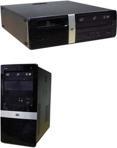
Figure 1-2 HP Pro 3000/3010 Small Form Factor
Figure 1-3 HP Pro 3010 Microtower
2 Chapter 1 Product Features
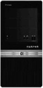
Figure 1-4 HP Pro 3080 Microtower
3
Microtower Models
Serviceability Features
The Microtower computer includes features that make it easy to upgrade and service. A Torx T-15 or flat blade screwdriver is needed for many of the installation procedures described in this guide.
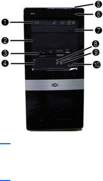
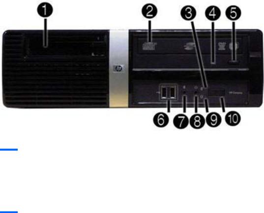
Front Panel Components
Front bezel appearance and drive configuration varies by model.
Figure 1-5 Front Panel Components
Table 1-1 Front Panel Components
1 |
5.25-inch Optical Drive1 |
6 |
Hard Drive Activity Light |
|
|
|
|
2 |
5.25-inch Optical Drive Bay |
7 |
Optical Drive Eject Button |
|
|
|
|
3 |
3.5-inch Media Card Reader (optional)2 |
8 |
Microphone Connector |
|
|
|
|
4 |
Recovery/Reset Button3 |
9 |
Headphone Connector |
|
|
|
|
5 |
Dual-State Power Button |
10 |
USB (Universal Serial Bus) 2.0 Ports |
1Some models have bezel blanks covering one or both of the 5.25-inch drive bays.
2Some models have a bezel blank covering the 3.5-inch drive bay.
3Not available on all models
4 Chapter 1 Product Features

Media Card Reader Components
The media card reader is an optional device available on some models only. Refer to the following illustration and table to identify the media card reader components.
Figure 1-6 Media Card Reader Components
Table 1-2 Media Card Reader Components
No. |
Slot |
Media |
|
|
|
|
|
|
|
1 |
xD |
● |
xD-Picture Card (xD) |
|
|
|
|
|
|
2 |
MicroSD |
● |
MicroSD (T-Flash) |
● MicroSDHC |
3Media Card Reader Activity Light
4 |
SD/MMC+/miniSD |
● |
Secure Digital (SD) |
● |
MiniSDHC |
● |
MultiMediaCard 4.0 |
|
|
● |
Secure Digital High |
● |
MultiMediaCard |
|
(MMC Plus) |
|
|
● |
|
||||
|
|
|
Capacity (SDHC) |
|
(MMC) |
Reduced Size |
|
|
|
● |
MiniSD |
● |
Reduced Size |
|
MultiMediaCard 4.0 |
|
|
|
(MMC Mobile) |
||||
|
|
|
|
|
MultiMediaCard (RS |
● |
|
|
|
|
|
|
MMC) |
MMC Micro (adapter |
|
|
|
|
|
|
|
|
required) |
|
|
|
|
|
|
|
|
5 |
USB |
● |
USB (Universal Serial |
|
|
|
|
|
|
|
Bus) Port |
|
|
|
|
|
|
|
|
|
|
|
|
6 |
CompactFlash I/II |
● |
CompactFlash Card |
● |
CompactFlash Card |
● |
MicroDrive |
|
|
|
Type 1 |
|
Type 2 |
|
|
|
|
|
|
|
|
|
|
7 |
MS PRO/MS PRO DUO |
● |
Memory Stick (MS) |
● |
Memory Stick Select |
● |
Memory Stick PRO |
|
|
● |
MagicGate Memory |
● |
Memory Stick Duo |
|
Duo (MS PRO Duo) |
|
|
● |
|
||||
|
|
|
Stick (MG) |
|
(MS Duo) |
Memory Stick PRO- |
|
|
|
● |
MagicGate Memory |
● |
Memory Stick PRO |
|
HG Duo |
|
|
● |
|
||||
|
|
|
Duo |
|
(MS PRO) |
Memory Stick Micro |
|
|
|
|
|
|
|
|
(M2) (adapter |
|
|
|
|
|
|
|
required) |
|
|
|
|
|
|
|
|
Microtower Models |
5 |

Rear Panel Components
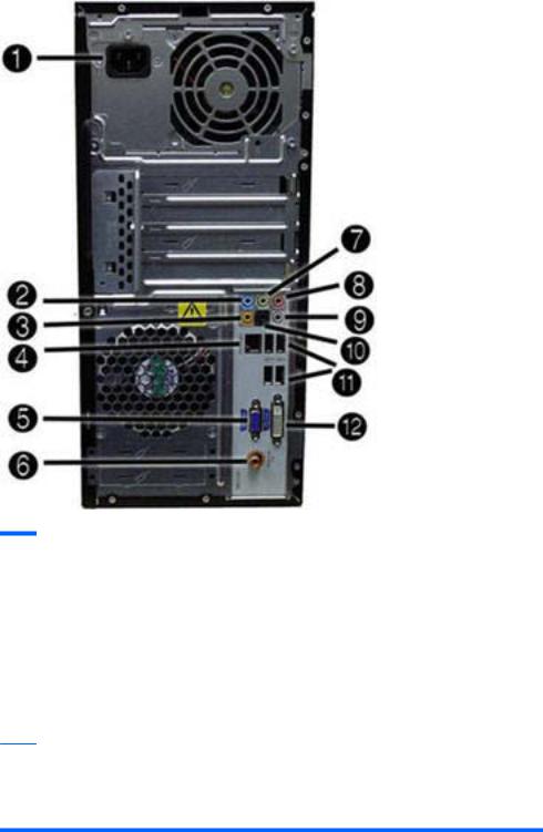
HP Pro 3000 MT/3080 MT
Figure 1-7 Rear Panel Components – HP Pro 3000/3080 MT
Table 1-3 Rear Panel Components – HP Pro 3000/3080 MT
1 |
Power Cord Connector |
7 |
Line-Out Connector for powered audio |
|
|
|
devices (green) |
|
|
|
|
2 |
Line-In Audio Connector (blue) |
8 |
Microphone Connector (pink) |
|
|
|
|
3 |
RJ-45 Network Connector |
9 |
DVI Connector |
|
|
|
|
4 |
Universal Serial Bus (USB) Ports |
10 |
Serial connector |
|
|
|
|
5 |
VGA Monitor Connector |
11 |
Keyboard PS/2 connector |
|
|
|
|
6 |
Mouse PS/2 connector |
|
|
NOTE: Arrangement and number of connectors may vary by model.
When a device is plugged into the blue Line-In Audio Connector, a dialog box will pop up asking if you want to use the connector for a line-in device or a microphone. You can reconfigure the connector at any time by double-clicking the Realtek HD Audio Manager icon in the Windows taskbar.
6 Chapter 1 Product Features
HP Pro 3010 MT
Figure 1-8 Rear Panel Components – HP Pro 3010 MT
Table 1-4 Rear Panel Components – HP Pro 3010 MT
1 |
Power Cord Connector |
7 |
Line-Out Connector for powered audio |
|
|
|
devices (green) |
|
|
|
|
2 |
Line-In Audio Connector (blue) |
8 |
Microphone Connector (pink) |
|
|
|
|
3 |
Rear Center Channel/Subwoofer Audio |
9 |
Surround Side Channel Audio |
|
Connector (orange) |
|
Connector (gray) |
|
|
|
|
4 |
RJ-45 Network Connector |
10 |
Surround Rear Channel Audio |
|
|
|
Connector (black) |
|
|
|
|
5 |
VGA Monitor Connector |
11 |
Universal Serial Bus (USB) Ports |
|
|
|
|
6 |
Digital Audio Out Connector |
12 |
DVI Connector |
NOTE: Arrangement and number of connectors may vary by model.
When a device is plugged into the blue Line-In Audio Connector, a dialog box will pop up asking if you want to use the connector for a line-in device or a microphone. You can reconfigure the connector at any time by double-clicking the Realtek HD Audio Manager icon in the Windows taskbar.
Microtower Models |
7 |
Small Form Factor Models
Serviceability Features
The small form factor computer includes features that make it easy to upgrade and service. A Torx T-15 or flat blade screwdriver is needed for many of the installation procedures described in this guide.
Front Panel Components
Drive configuration may vary by model.
Figure 1-9 Front Panel Components
Table 1-5 Front Panel Components
1 |
Media card reader (optional)2 |
6 |
USB (Universal Serial Bus) 2.0 Ports |
|
|
|
|
2 |
5.25-inch Optical Drive (optional)1 |
7 |
Microphone Connector |
|
|
|
|
4 |
Hard Drive Activity Light |
8 |
Headphone Connector |
|
|
|
|
3 |
Optical Drive Activity Light |
9 |
Power On Light |
|
|
|
|
5 |
Optical Drive Eject Button |
10 |
Dual-State Power Button |
1Some models have a bezel blank covering the 3.5-inch drive bay.
2Some models have a bezel blank covering the 5.25-inch drive bay.
8 Chapter 1 Product Features
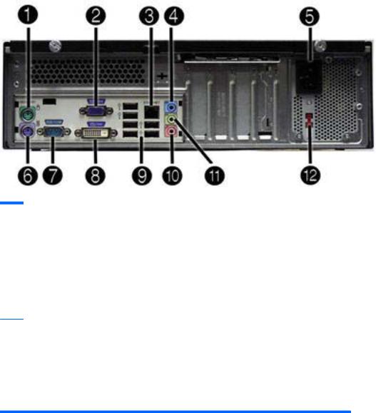
Rear Panel Components
HP Pro 3000 SFF
Figure 1-10 Rear Panel Components – HP Pro 3000 SFF
Table 1-6 Rear Panel Components – HP Pro 3000 SFF
1 |
Mouse PS/2 Connector |
7 |
Serial Connector |
|
|
|
|
2 |
VGA Monitor Connector (blue) |
8 |
DVI Connector |
|
|
|
|
3 |
RJ-45 Network Connector |
9 |
Universal Serial Bus (USB) Ports |
|
|
|
|
4 |
Line-In Audio Connector (blue) |
10 |
Microphone Connector (pink) |
|
|
|
|
5 |
Power Cord Connector |
11 |
Line-Out Connector for powered audio |
|
|
|
devices (green) |
|
|
|
|
6 |
Keyboard PS/2 Connector |
12 |
Voltage Select Switch |
NOTE: Arrangement and number of connectors may vary by model.
The monitor connector on the system board is inactive when a PCI Express x16 graphics card is installed in the computer.
If a PCI Express x1 graphics card is installed, the connectors on the card and the system board may be used at the same time. Some settings may need to be changed in Computer Setup to use both connectors. For information about setting the boot VGA controller, refer to the Computer Setup (F10) Utility Guide.
Small Form Factor Models |
9 |

HP Pro 3010 SFF
Figure 1-11 Rear Panel Components – HP Pro 3010 SFF
Table 1-7 Rear Panel Components – HP Pro 3010 SFF
1 |
Digital Audio Out Connector |
8 |
Universal Serial Bus (USB) Ports |
|
|
|
|
2 |
VGA Monitor Connector (blue) |
9 |
Surround Rear Channel Audio |
|
|
|
Connector (black) |
|
|
|
|
3 |
RJ-45 Network Connector |
10 |
Surround Side Channel Audio |
|
|
|
Connector (gray) |
|
|
|
|
4 |
Rear Center Channel/Subwoofer Audio |
11 |
Microphone Connector (pink) |
|
Connector (orange) |
|
|
|
|
|
|
5 |
Line-In Audio Connector (blue) |
12 |
Line-Out Connector for powered audio |
|
|
|
devices (green) |
|
|
|
|
6 |
Power Cord Connector |
13 |
Voltage Select Switch |
|
|
|
|
7 |
DVI Connector |
|
|
NOTE: Arrangement and number of connectors may vary by model.
The monitor connector on the system board is inactive when a PCI Express x16 graphics card is installed in the computer.
If a PCI Express x1 graphics card is installed, the connectors on the card and the system board may be used at the same time. Some settings may need to be changed in Computer Setup to use both connectors. For information about setting the boot VGA controller, refer to the Computer Setup (F10) Utility Guide.
10 Chapter 1 Product Features
2Installing and Customizing the Software
If your computer was not shipped with a Microsoft operating system, some portions of this documentation do not apply. Additional information is available in online help after you install the operating system.
 NOTE: If the computer was shipped with Windows Vista or Windows 7 loaded, you will be prompted to register the computer with HP Total Care before installing the operating system. You will see a brief movie followed by an online registration form. Fill out the form, click the Begin button, and follow the instructions on the screen.
CAUTION: Do not add optional hardware or third-party devices to the computer until the operating system is successfully installed. Doing so may cause errors and prevent the operating system from installing properly.
 NOTE: Be sure there is a 10.2-cm (4-inch) clearance at the back of the unit and above the monitor to permit the required airflow.
Installing the Operating System
The first time you turn on the computer, the operating system is installed automatically. This process takes about 5 to 10 minutes, depending on which operating system is being installed. Carefully read and follow the instructions on the screen to complete the installation.
CAUTION: Once the automatic installation has begun, DO NOT TURN OFF THE COMPUTER UNTIL THE PROCESS IS COMPLETE. Turning off the computer during the installation process may damage the software that runs the computer or prevent its proper installation.
 NOTE: If the computer shipped with more than one operating system language on the hard drive, the installation process could take up to 60 minutes.
If your computer was not shipped with a Microsoft operating system, some portions of this documentation do not apply. Additional information is available in online help after you install the operating system.
Downloading Microsoft Windows Updates
1.To set up your Internet connection, click Start > Internet Explorer and follow the instructions on the screen.
2.Once an Internet connection has been established, click the Start button.
3.Select the All Programs menu.
Installing the Operating System 11
4.Click on the Windows Update link.
In Windows Vista and Windows 7, the Windows Update screen appears. Click view available updates and make sure all critical updates are selected. Click the Install button and follow the instructions on the screen.
In Windows XP, you will be directed to the Microsoft Windows Update Web site. If you see one or more pop-up windows that ask you to install a program from http://www.microsoft.com, click Yes to install the program. Follow the instructions on the Microsoft Web site to scan for updates and install critical updates and service packs.
It is recommended that you install all of the critical updates and service packs.
5.After the updates have been installed, Windows will prompt you to reboot the machine. Be sure to save any files or documents that you may have open before rebooting. Then select Yes to reboot the machine.
Installing or Upgrading Device Drivers (Windows systems)
When installing optional hardware devices after the operating system installation is complete, you must also install the drivers for each of the devices.
If prompted for the i386 directory, replace the path specification with C:\i386, or use the Browse button in the dialog box to locate the i386 folder. This action points the operating system to the appropriate drivers.
Obtain the latest support software, including support software for the operating system from http://www.hp.com/support. Select your country and language, select Download drivers and software (and firmware), enter the model number of the computer, and press Enter.
Accessing Disk Image (ISO) Files
There are disk image files (ISO files) included on your PC that contain the installation software for additional software. These CD image files are located in the folder C:\SWSetup\ISOs. Each .iso file can be burned to CD media to create an installation CD. It is recommended that these disks be created and the software installed in order to get the most from your PC. The software and image file names are:
●Corel WinDVD SD and BD – installation software for WinDVD – used to play DVD movies
●HP Insight Diagnostics OR Vision Diagnostics – software to perform diagnostic activities on your PC
Protecting the Software
To protect the software from loss or damage, keep a backup copy of all system software, applications, and related files stored on the hard drive. Refer to the operating system or backup utility documentation for instructions on making backup copies of your data files.
12 Chapter 2 Installing and Customizing the Software

3 Computer Setup (F10) Utility
The computer setup utility differs for the HP Pro 3000/3080 and the HP Pro 3010.
HP Pro 3000/3080 – Computer Setup (F10) Utility
Use Computer Setup (F10) Utility to do the following:
●Change factory default settings.
●Set the system date and time.
●Set, view, change, or verify the system configuration, including settings for processor, graphics, memory, audio, storage, communications, and input devices.
●Modify the boot order of bootable devices such as hard drives, diskette drives, optical drives, or USB flash media devices.
●Restrict a device from booting the unit.
●Run hard drive self-tests.
●View CPU and system temperatures.
●Establish a supervisor password that controls access to Computer Setup (F10) Utility and the settings described in this section.
●Secure integrated I/O functionality, including the serial, USB, or parallel ports, audio, or embedded NIC, so that they cannot be used until they are unsecured.
●Enable or disable pre-boot messages.
●Enable or disable USB legacy support.
Using Computer Setup (F10) Utilities
Computer Setup can be accessed only by turning the computer on or restarting the system. To access the Computer Setup Utilities menu, complete the following steps:
1.Turn on or restart the computer.
2.As soon as the computer is turned on, press F10 before the system boots to the operating system to enter Computer Setup. Press Enter to bypass the title screen, if necessary.
 NOTE: If you do not press F10 at the appropriate time, you must restart the computer and again press F10 before the unit boots to the operating system to access the utility.
3.The Computer Setup Utility screen is divided into menu headings and actions.
HP Pro 3000/3080 – Computer Setup (F10) Utility 13

Six menu headings appear on the Computer Setup Utility screen:
●Main
●Advanced
●Boot
●Power
●PC Health
●Exit
Use the arrow keys to select the appropriate heading, then press Enter. Use the arrow (up and down) keys to select the option you want, then press Enter. To return to the previous screen, press Esc.
4.To apply and save changes, press the F10 key.
If you have made changes that you do not want applied, press the F5 key to return to the previous values.
To load optimized default values, press the F7 key.
CAUTION: Do NOT turn the computer power OFF while the ROM is saving the Computer Setup (F10) changes because the CMOS could become corrupted. It is safe to turn off the computer only after exiting the F10 Setup screen.
Table 3-1 Computer Setup (F10) Utility Main Menu
Heading |
Table |
|
|
Main |
Computer Setup—Main on page 15 |
|
|
Advanced |
Computer Setup—Advanced on page 16 |
|
|
Boot |
Computer Setup—Boot on page 17 |
|
|
Power |
Computer Setup—Power on page 18 |
|
|
PC Health |
Computer Setup—PC Health on page 18 |
|
|
Exit |
Computer Setup—Exit on page 19 |
|
|
14 Chapter 3 Computer Setup (F10) Utility

Computer Setup—Main
 NOTE: Support for specific Computer Setup options may vary depending on the hardware configuration.
Table 3-2 Computer Setup—Main
Option |
Description |
||
|
|
||
System Information |
Allows you to view the following system information: |
||
|
● Product Name (view only) |
||
|
● SKU Number (view only) |
||
|
● Processor Type (view only) |
||
|
● Processor Speed (view only) |
||
|
● |
CPUID/PatchID (view only) |
|
|
● Cache Size (view only) |
||
|
● Memory Size (view only) |
||
|
● Integrated MAC (view only) |
||
|
● System BIOS (view only) |
||
|
● Chassis Serial Number (view only) |
||
|
● Asset Tag Number (press Enter to change) |
||
|
● |
UUID (view only) |
|
|
|
||
Set Time and Date |
Allows you to set system time and date. |
||
|
|
||
SATA Port 1 |
Allows or displays the following for each SATA Port: |
||
SATA Port 2 |
● |
Port Configuration — Disable/enable SATA Port |
|
SATA Port 3 |
● |
HDD Self-Test for selected channel: |
|
SATA Port 4 |
|
◦ |
SMART Status Check |
|
|
◦ |
HDD Short Self-Test |
|
|
◦ |
HDD Extended Self-Test |
|
● |
Vendor (view only) |
|
|
● |
Size (view only) |
|
|
● |
Firmware (view only) |
|
|
|
||
SATA Emulation |
Allows you to choose how the SATA controller and devices are accessed by the operating |
||
|
system. The following options are available: |
||
|
● |
IDE |
|
|
● |
RAID |
|
|
● |
AHCI |
|
|
|
||
Onboard FDC |
Disables/enables the floppy disk controller. |
||
Controller |
|
|
|
|
|
||
Drive A |
(view only) |
||
|
|
|
|
HP Pro 3000/3080 – Computer Setup (F10) Utility 15

Table 3-2 Computer Setup—Main (continued)
Option |
Description |
|
|
|
|
Halt On |
Allows you to set POST error behavior to: |
|
|
● |
No Errors |
|
● |
All Errors |
|
● |
All But Keyboard |
|
|
|
POST Delay |
Allows you to set a POST delay to: |
|
|
● |
0 seconds |
|
● |
5 seconds |
|
● |
10 seconds |
|
● |
15 seconds |
|
● |
30 seconds |
|
|
|
Computer Setup—Advanced
 NOTE: Support for specific Computer Setup options may vary depending on the hardware configuration.
Table 3-3 Computer Setup—Advanced
Option |
Description |
|
|
|
|
Execute Disable Bit |
Disables/enables hardware DEP function. |
|
|
|
|
Init Display First |
Allows you to select the primary display device: |
|
|
● |
OnChip VGA |
|
● |
PCI Slot |
|
● |
PCIEx |
|
|
|
MAX DVMT Allocation |
Allows you to specify the DVMT/system memory allocated for video memory.: |
|
|
● |
128MB |
|
● |
256MB |
|
● |
Max |
|
|
|
Onboard HD Audio |
Allows you to disable/enable onboard HD audio. |
|
|
|
|
OnChip USB |
Disables/enables the universal host controller interface for USB (Universal Serial Bus). |
|
Controller |
|
|
|
|
|
USB Legacy Support |
Disables/enables USB legacy support function (USB keyboard, USB mouse, and USB flash |
|
|
media). |
|
|
|
|
Onboard LAN |
Disables/enables onboard LAN controller. |
|
|
|
|
Onboard LAN Boot |
Disables/enables the boot ROM of the onboard LAN chip. |
|
ROM |
|
|
|
|
|
16 Chapter 3 Computer Setup (F10) Utility

Table 3-3 Computer Setup—Advanced (continued)
Option Description
Onboard Serial Port 1 Allows you to select a setting for the onboard serial port:
|
● |
Disabled |
|
● |
3F8/IRQ4 |
|
● |
2F8/IRQ3 |
|
● |
3E8/IRQ4 |
|
● |
2E8/IRQ3 |
|
|
|
PCI Device SERR# |
Disables/enables SERR#. |
|
|
|
|
Computer Setup—Boot
 NOTE: Support for specific Computer Setup options may vary depending on the hardware configuration.
Table 3-4 Computer Setup—Boot
Option |
Description |
||
|
|
||
F9 Boot Menu |
Disables/enables F9 Boot Menu. |
||
|
|
||
F10 Setup Prompt |
Disables/enables the F10 Setup prompt message on the logo screen. |
||
|
|
||
F11 Recovery |
Disables/enables F11 Recovery and provides the option of showing the F11 Recovery prompt |
||
|
message on the logo screen. Choose from the following: |
||
|
● |
Disabled |
|
|
● |
Enabled no prompt |
|
|
● |
Enabled and prompt |
|
|
|
||
F12 Boot from LAN |
Disables/enables the F12 Boot from LAN prompt message on the logo screen. |
||
Prompt |
|
|
|
|
|
||
Hard Disk Boot Seq. |
Allows you to specify the order of attached hard drive devices (such as USB HDD storage or USB |
||
|
flash media). The first drive in the order has priority in the boot sequence and is recognized as |
||
|
drive C (if any devices are attached). |
||
|
|
||
Optical Drive Boot |
Allows you to specify the order in which attached optical drives (including USB ODD) are checked |
||
Seq. |
for a bootable operating system image. |
||
|
|
||
Network Boot Seq. |
Allows you to specify the order in which network devices (including UP NIC cards) are checked for |
||
|
a bootable operating system image. |
||
|
|
||
First Boot Device |
Allows you to specify which devices will boot first, second, third, and fourth or to disable any of the |
||
Second Boot Device |
four: |
|
|
● |
Removable |
||
Third Boot Device |
|||
● |
CDROM |
||
Fourth Boot Device |
|||
● |
Hard Disk |
||
|
|||
|
● |
Network |
|
|
NOTE: MS-DOS drive lettering assignments may not apply after a non-MS-DOS operating |
||
|
system has started. |
||
|
|
|
|
HP Pro 3000/3080 – Computer Setup (F10) Utility 17

Table 3-4 Computer Setup—Boot (continued)
Option |
Description |
|
|
Set Supervisor |
Allows you to establish a password to control access to Computer Setup. |
Password |
|
|
|
BIOS Write Protection |
Disables/enables BIOS upgrading. |
|
|
Computer Setup—Power
 NOTE: Support for specific Computer Setup options may vary depending on the hardware configuration.
Table 3-5 Computer Setup—Power
Option |
Description |
After AC Power Loss Allows you to select system power loss behavior:
●Off
●On
●Last State
Wake on PCI Device Disables/enables waking up from S5 by PCI device. from S5
RTC Alarm Resume Disables/enables RTC (real-time clock) alarm.
Computer Setup—PC Health
 NOTE: Support for specific Computer Setup options may vary depending on the hardware configuration.
Table 3-6 Computer Setup—PC Health
Option |
Description |
|
|
Chassis Opened |
Allows you to disable/enable the chassis intrusion function and clear the intrusion warning. |
Warning |
|
|
|
System Fan Fail |
Disables/enables detection of system fan during POST. |
Check |
|
|
|
Smart Fan Function |
Disables/enables Smart Fan functionality. Enabling optimizes fan control for best acoustic |
|
behavior. |
|
|
Current CPU |
(view only) |
Temperature |
|
|
|
Current System |
(view only) |
Temperature |
|
|
|
Current CPU Fan |
(view only) |
Speed |
|
|
|
Current System Fan |
(view only) |
Speed |
|
|
|
18 Chapter 3 Computer Setup (F10) Utility

Computer Setup—Exit
Table 3-7 Computer Setup—Exit
Option |
Description |
|
|
Save Changes and Exit |
Allows you to save current settings and exit Computer Setup. |
|
|
Discard Changes and |
Allows you to exit Computer Setup without saving changes. |
Exit |
|
|
|
Load Optimal Defaults |
Allows you to reset Computer Setup to factory defaults. |
|
|
HP Pro 3010 – Computer Setup (F10) Utility
Use Computer Setup (F10) Utility to do the following:
●Change factory default settings.
●Set the system date and time.
●Set, view, change, or verify the system configuration, including settings for processor, graphics, memory, audio, storage, communications, and input devices.
●Modify the boot order of bootable devices such as hard drives, diskette drives, optical drives, or USB flash media devices.
●Restrict a device from booting the unit.
●Run hard drive self-tests.
●View CPU and system temperatures.
●Establish a supervisor password that controls access to Computer Setup (F10) Utility and the settings described in this section.
●Secure integrated I/O functionality, including the serial, USB, or parallel ports, audio, or embedded NIC, so that they cannot be used until they are unsecured.
●Enable or disable pre-boot messages.
●Enable or disable USB legacy support.
Using Computer Setup (F10) Utilities
Computer Setup can be accessed only by turning the computer on or restarting the system. To access the Computer Setup Utilities menu, complete the following steps:
1.Turn on or restart the computer.
2.As soon as the computer is turned on, press F10 before the system boots to the operating system to enter Computer Setup. Press Enter to bypass the title screen, if necessary.
 NOTE: If you do not press F10 at the appropriate time, you must restart the computer and again press F10 before the unit boots to the operating system to access the utility.
3.The Computer Setup Utility screen is divided into menu headings and actions.
HP Pro 3010 – Computer Setup (F10) Utility 19

Five menu headings appear on the Computer Setup Utility screen:
●Main
●Advanced
●Boot
●Power
●Exit
Use the arrow keys to select the appropriate heading, then press Enter. Use the arrow (up and down) keys to select the option you want, then press Enter. To return to the previous screen, press Esc.
4.To apply and save changes, press the F10 key.
If you have made changes that you do not want applied, press the F5 key to return to the previous values.
To load optimized default values, press the F7 key.
CAUTION: Do NOT turn the computer power OFF while the ROM is saving the Computer Setup (F10) changes because the CMOS could become corrupted. It is safe to turn off the computer only after exiting the F10 Setup screen.
Table 3-8 Computer Setup (F10) Utility Main Menu
Heading |
Table |
|
|
Main |
Computer Setup—Main on page 15 |
|
|
Advanced |
Computer Setup—Advanced on page 16 |
|
|
Boot |
Computer Setup—Boot on page 17 |
|
|
Power |
Computer Setup—PC Health on page 18 |
|
|
Exit |
Computer Setup—Exit on page 24 |
|
|
Computer Setup—Main
 NOTE: Support for specific Computer Setup options may vary depending on the hardware configuration.
Table 3-9 Computer Setup—Main
Option |
Description |
|
|
System Time |
Allows you to set system time. |
|
|
System Date |
Allows you to set system date. |
|
|
Language |
Allows you to select language. |
|
|
20 Chapter 3 Computer Setup (F10) Utility
Loading...