


|
|
|
|
|
|
|
|
|
|
PN: 51512:E |
ECN 05-040 |
|
|
|
|
|
|
|
|
|
|
|
|
|
|
|
|
|
|
|
|
|
|
|
|
Fire Alarm Control Panel
MS-2 & MS-4 MS-2E & MS-4E
Document #51512 E
01/18/05 Revision:
Fire Alarm System Limitations
An automatic fire alarm system–typically made up of smoke detectors, heat detectors, manual pull stations, audible warning devices, and a fire alarm control with remote notification capability–can provide early warning of a developing fire. Such a system, however, does not assure protection against property damage or loss of life resulting from a fire.
The Manufacturer recommends that smoke and/or heat detectors be located throughout a protected premise following the recommendations of the current edition of the National Fire Protection Association Standard 72 (NFPA 72), manufacturer's recommendations, State and local codes, and the recommendations contained in the Guide for Proper Use of System Smoke Detectors, which is made available at no charge to all installing dealers. A study by the Federal Emergency Management Agency (an agency of the United States government) indicated that smoke detectors may not go off in as many as 35% of all fires. While fire alarm systems are designed to provide early warning against fire, they do not guarantee warning or protection against fire. A fire alarm system may not provide timely or adequate warning, or simply may not function, for a variety of reasons:
Smoke detectors may not sense fire where smoke cannot reach the detectors such as in chimneys, in or behind walls, on roofs, or on the other side of closed doors. Smoke detectors also may not sense a fire on another level or floor of a building. A second-floor detector, for example, may not sense a first-floor or basement fire.
Particles of combustion or "smoke" from a developing fire may not reach the sensing chambers of smoke detectors because:
•Barriers such as closed or partially closed doors, walls, or chimneys may inhibit particle or smoke flow.
•Smoke particles may become "cold," stratify, and not reach the ceiling or upper walls where detectors are located.
•Smoke particles may be blown away from detectors by air outlets.
•Smoke particles may be drawn into air returns before reaching the detector.
The amount of "smoke" present may be insufficient to alarm smoke detectors. Smoke detectors are designed to alarm at various levels of smoke density. If such density levels are not created by a developing fire at the location of detectors, the detectors will not go into alarm.
Smoke detectors, even when working properly, have sensing limitations. Detectors that have photoelectronic sensing chambers tend to detect smoldering fires better than flaming fires, which have little visible smoke. Detectors that have ion- izing-type sensing chambers tend to detect fast-flaming fires better than smoldering fires. Because fires develop in different ways and are often unpredictable in their growth, neither type of detector is necessarily best and a given type of detector may not provide adequate warning of a fire.
Smoke detectors cannot be expected to provide adequate warning of fires caused by arson, children playing with matches (especially in bedrooms), smoking in bed, and violent explosions (caused by escaping gas, improper storage of flammable materials, etc.).
While a fire alarm system may lower insurance rates, it is not a substitute for fire insurance!
Heat detectors do not sense particles of combustion and alarm only when heat on their sensors increases at a predetermined rate or reaches a predetermined level. Rate-of-rise heat detectors may be subject to reduced sensitivity over time. For this reason, the rate-of-rise feature of each detector should be tested at least once per year by a qualified fire protection specialist.
Heat detectors are designed to protect property, not life.
IMPORTANT! Smoke detectors must be installed in the same room as the control panel and in rooms used by the system for the connection of alarm transmission wiring, communications, signaling, and/or power. If detectors are not so located, a developing fire may damage the alarm system, crippling its ability to report a fire.
Audible warning devices such as bells may not alert people if these devices are located on the other side of closed or partly open doors or are located on another floor of a building. Any warning device may fail to alert people with a disability or those who have recently consumed drugs, alcohol or medication. Please note that:
•Strobes can, under certain circumstances, cause seizures in people with conditions such as epilepsy.
•Studies have shown that certain people, even when they hear a fire alarm signal, do not respond or comprehend the meaning of the signal. It is the property owner's responsibility to conduct fire drills and other training exercise to make people aware of fire alarm signals and instruct them on the proper reaction to alarm signals.
•In rare instances, the sounding of a warning device can cause temporary or permanent hearing loss.
A fire alarm system will not operate without any electrical power. If AC power fails, the system will operate from standby batteries only for a specified time and only if the batteries have been properly maintained and replaced regularly.
Equipment used in the system may not be technically compatible with the control. It is essential to use only equipment listed for service with your control panel.
Telephone lines needed to transmit alarm signals from a premise to a central monitoring station may be out of service or temporarily disabled. For added protection against telephone line failure, backup radio transmission systems are recommended.
The most common cause of fire alarm malfunction is inadequate maintenance. To keep the entire fire alarm system in excellent working order, ongoing maintenance is required per the manufacturer's recommendations, and UL and NFPA standards. At a minimum, the requirements of NFPA 72 shall be followed. Environments with large amounts of dust, dirt or high air velocity require more frequent maintenance. A maintenance agreement should be arranged through the local manufacturer's representative. Maintenance should be scheduled monthly or as required by National and/or local fire codes and should be performed by authorized professional fire alarm installers only. Adequate written records of all inspections should be kept.
PrecauLarge.PMD 01/10/2005

Installation Precautions
WARNING - Several different sources of power can be connected to the fire alarm control panel. Disconnect all sources of power before servicing. Control unit and associated equipment may be damaged by removing and/or inserting cards, modules, or interconnecting cables while the unit is energized. Do not attempt to install, service, or operate this unit until this manual is read and understood.
CAUTION - System Reacceptance Test after Software Changes. To ensure proper system operation, this product must be tested in accordance with NFPA 72 after any programming operation or change in site-specific software. Reacceptance testing is required after any change, addition or deletion of system components, or after any modification, repair or adjustment to system hardware or wiring.
All components, circuits, system operations, or software functions known to be affected by a change must be 100% tested. In addition, to ensure that other operations are not inadvertently affected, at least 10% of initiating devices that are not directly affected by the change, up to a maximum of 50 devices, must also be tested and proper system operation verified.
This system meets NFPA requirements for indoor dry operation at 0-49° C/32-120° F and at a relative humidity of 93 ±2% RH (non-condensing) at 32 ±2° C/90 ±3° F. However, the useful life of the system's standby batteries and the electronic components may be adversely affected by extreme temperature ranges and humidity. Therefore, it is recommended that this system and all peripherals be installed in an environment with a nominal room temperature of 15-27° C/60-80° F.
Verify that wire sizes are adequate for all initiating and indicating device loops. Most devices cannot tolerate more than a 10% I.R. drop from the specified device voltage.
Adherence to the following will aid in problem-free installation with long-term reliability:
Like all solid state electronic devices, this system may operate erratically or can be damaged when subjected to lightning-induced transients. Although no system is completely immune from lightning transients and interferences, proper grounding will reduce susceptibility. Overhead or outside aerial wiring is not recommended, due to an increased susceptibility to nearby lightning strikes. Consult with the Technical Services Department if any problems are anticipated or encountered.
Disconnect AC power and batteries prior to removing or inserting circuit boards. Failure to do so can damage circuits.
Remove all electronic assemblies prior to any drilling, filing, reaming, or punching of the enclosure. When possible, make all cable entries from the sides or rear. Before making modifications, verify that they will not interfere with battery, transformer, and printed circuit board location.
Do not tighten screw terminals more than 9 in-lbs. Over-tightening may damage threads, resulting in reduced terminal contact pressure and difficulty with screw terminal removal.
Though designed to last many years, system components can fail at any time. This system contains static-sensitive components. Always ground yourself with a proper wrist strap before handling any circuits so that static charges are removed from the body. Use static-suppressive packaging
to protect electronic assemblies removed from the unit.
Follow the instructions in the installation, operating, and programming manuals. These instructions must be followed to avoid damage to the control panel and associated equipment. FACP operation and reliability depend upon proper installation by authorized personnel.
FCC Warning
WARNING: This equipment generates, uses, and can ra- |
Canadian Requirements |
|
diate radio frequency energy and if not installed and used |
This digital apparatus does not exceed the Class A |
|
in accordance with the instruction manual, may cause in- |
limits for radiation noise emissions from digital |
|
terference to radio communications. It has been tested |
apparatus set out in the Radio Interference Regulations |
|
and found to comply with the limits for class A computing |
of the Canadian Department of Communications. |
|
device pursuant to Subpart B of Part 15 of FCC Rules, |
Le present appareil numerique n'emet pas de bruits |
|
which is designed to provide reasonable protection against |
||
radioelectriques depassant les limites applicables aux |
||
such interference when operated in a commercial environ- |
||
appareils numeriques de la classe A prescrites dans le |
||
ment. Operation of this equipment in a residential area is |
||
Reglement sur le brouillage radioelectrique edicte par le |
||
likely to cause interference, in which case the user will be |
||
ministere des Communications du Canada. |
||
required to correct the interference at his own expense. |
||
|
PrecauLarge.PMD 01/10/2005
Notes
4 |
MS-2/MS-4 PN 51512:E 01/18/05 |
Table of Contents
SECTION 1: Product Description ........................................................................................................................ |
10 |
1.1: Product Features.......................................................................................................................................... |
10 |
1.2: Specifications .............................................................................................................................................. |
12 |
1.3: Controls and Indicators ............................................................................................................................... |
13 |
1.4: Circuits ........................................................................................................................................................ |
14 |
1.5: Components................................................................................................................................................. |
14 |
1.6: Optional Modules and Accessories ............................................................................................................. |
15 |
SECTION 2: Installation ....................................................................................................................................... |
17 |
2.1: Backbox Mounting...................................................................................................................................... |
17 |
2.2: Operating Power.......................................................................................................................................... |
19 |
2.3: Input Circuits............................................................................................................................................... |
20 |
2.4: Output Circuits ............................................................................................................................................ |
22 |
2.4.1: Notification Appliance Circuits ........................................................................................................ |
22 |
2.4.2: Special Application DC Power Output Connections ........................................................................ |
23 |
2.4.3: Relays................................................................................................................................................ |
23 |
2.5: Power-limited Wiring Requirements........................................................................................................... |
24 |
2.6: Installation of Optional Modules................................................................................................................. |
25 |
2.6.1: CAC-4 Class A Converter Module (MS-4 only) .............................................................................. |
25 |
2.6.1.1 Installation ............................................................................................................................... |
25 |
2.6.1.2 Wiring NACs and IDCs for Class A ....................................................................................... |
26 |
2.6.2: 4XTMF, 4XLMF and 4XZMF Option Modules............................................................................... |
27 |
2.6.2.1 4XTMF Transmitter Module Installation ............................................................................... |
28 |
2.6.2.2 4XZMF Zone Relay Module (MS-4 only) .............................................................................. |
29 |
2.6.2.3 4XLMF LED Interface Module (MS-4 only) ......................................................................... |
30 |
SECTION 3: Program Options via DIP Switch .................................................................................................. |
31 |
3.1: DIP Switch Settings .................................................................................................................................... |
32 |
3.1.1: SW1 DIP Switch Settings ................................................................................................................. |
34 |
3.1.1.1 Silence Inhibit ......................................................................................................................... |
34 |
3.1.1.2 Auto-silence ............................................................................................................................ |
34 |
3.1.1.3 Temporal Coding .................................................................................................................... |
34 |
3.1.1.4 Selective Silence ..................................................................................................................... |
34 |
3.1.1.5 Trouble Reminder ................................................................................................................... |
34 |
3.1.1.6 AC Trouble Delay ................................................................................................................... |
34 |
3.1.1.7 Autoresettable Supervisory ..................................................................................................... |
34 |
3.1.1.8 IDC Combination Circuit ........................................................................................................ |
34 |
3.1.2: SW2 DIP Switch Settings ................................................................................................................. |
35 |
3.1.2.1 IDC1 Verification (MS-4 only) .............................................................................................. |
35 |
3.1.2.2 IDC1 Supervisory (MS-4 only) ............................................................................................... |
35 |
3.1.2.3 IDC1 Verification for MS-2 or IDC2 Verification for MS-4 ................................................. |
35 |
3.1.2.4 IDC1 Supervisory for MS-2 or IDC2 Supervisory for MS-4 ................................................. |
35 |
3.1.2.5 IDC2 Verification for MS-2 or IDC3 Verification for MS-4 ................................................. |
36 |
3.1.2.6 IDC2 Supervisory for MS-2 or IDC3 Supervisory for MS-4 ................................................. |
36 |
3.1.2.7 IDC4 Verification (MS-4 only) ............................................................................................... |
36 |
3.1.2.8 IDC4 Supervisory (MS-4 only) ............................................................................................... |
36 |
3.1.3: SW3 DIP Switch Settings ................................................................................................................. |
36 |
3.1.3.1 NAC1 Nonsilenceable ............................................................................................................. |
36 |
3.1.3.2 NAC1 Disable ......................................................................................................................... |
36 |
3.1.3.3 NAC2 Nonsilenceable (MS-4 only) ........................................................................................ |
36 |
3.1.3.4 NAC2 Disable (MS-4 only) .................................................................................................... |
36 |
3.1.3.5 Strobe Synchronization ........................................................................................................... |
37 |
3.1.3.5.1 Maximum Number of Strobes for Synchronization ............................................................. |
37 |
3.1.3.6 Nonsilenceable Waterflow for Combination Circuit .............................................................. |
37 |
3.1.3.7 Spares ...................................................................................................................................... |
37 |
MS-2/MS-4 P/N: 51512:E 01/18/05 |
5 |
Table of Contents |
|
SECTION 4: Operating Instructions .................................................................................................................... |
38 |
4.1: Switch Functions in Normal Mode.............................................................................................................. |
38 |
4.1.1: ACK - Acknowledge......................................................................................................................... |
38 |
4.1.2: Silence ............................................................................................................................................... |
38 |
4.1.3: Zone Enable/Disable ......................................................................................................................... |
38 |
4.1.4: Reset/(Lamp Test) ............................................................................................................................. |
38 |
4.1.5: Walktest ............................................................................................................................................. |
39 |
4.2: Walktest ....................................................................................................................................................... |
39 |
4.3: Status LEDs ................................................................................................................................................. |
40 |
4.4: Operation ..................................................................................................................................................... |
41 |
4.4.1: Fire Alarm Response......................................................................................................................... |
42 |
4.4.2: Fire Alarm Restoral........................................................................................................................... |
42 |
4.4.3: System Supervisory Condition Response ......................................................................................... |
42 |
4.4.4: System Supervisory Restoral Response ............................................................................................ |
42 |
4.4.5: Trouble Condition Response ............................................................................................................. |
43 |
4.4.6: Trouble Condition Restoral ............................................................................................................... |
43 |
SECTION 5: Power Supply Calculations ............................................................................................................. |
44 |
5.1: Overview ..................................................................................................................................................... |
44 |
5.2: Calculating the AC Branch Circuit.............................................................................................................. |
44 |
5.3: Calculating the System Current Draw......................................................................................................... |
45 |
5.3.1: Overview ........................................................................................................................................... |
45 |
5.3.2: How to Use Table 5-3 on page 46 to Calculate System Current Draw ............................................. |
45 |
5.4: Calculating the Battery Size ........................................................................................................................ |
47 |
5.4.1: NFPA Battery Requirements ............................................................................................................. |
47 |
5.4.2: Selecting and Locating Batteries....................................................................................................... |
47 |
6 |
MS-2/MS-4 P/N: 51512:E 01/18/05 |

It is imperative that the installer understand the requirements of the Authority Having Jurisdiction (AHJ) and be familiar with the standards set forth by the following regulatory agencies:
•Underwriters Laboratories Standards
•NFPA 72 National Fire Alarm Code
Before proceeding, the installer should be familiar with the following documents.
NFPA Standards
This Fire Alarm Control Panel complies with the following NFPA Standards:
NFPA 72 National Fire Alarm Code for Local Fire Alarm Systems and Remote Station Fire Alarm Systems (requires an optional Remote Station Output Module)
Underwriters Laboratories Documents for Reference:
UL 38 Manually Actuated Signaling Boxes
UL 217 Smoke Detectors, Single and Multiple Station
UL 228 Door Closers–Holders for Fire Protective Signaling Systems
UL 268 Smoke Detectors for Fire Protective Signaling Systems
UL 268A Smoke Detectors for Duct Applications
UL 346 Waterflow Indicators for Fire Protective Signaling Systems
UL 464 Audible Signaling Appliances
UL 521 Heat Detectors for Fire Protective Signaling Systems
UL 864 Standard for Control Units for Fire Protective Signaling Systems
UL 1481 Power Supplies for Fire Protective Signaling Systems
UL 1638 Visual Signaling Appliances
UL 1971 Signaling Devices for Hearing Impaired
Other:
NEC Article 250 Grounding
NEC Article 300 Wiring Methods
NEC Article 760 Fire Protective Signaling Systems
Applicable Local and State Building Codes
Requirements of the Local Authority Having Jurisdiction (LAHJ)
Fire•Lite Documents |
|
Fire•Lite Device Compatibility Document |
Document #15384 |
411 Digital Alarm Communicator/Transmitter |
Document #50921 |
411UD Digital Alarm Communicator/Transmitter |
Document #50759 |
This product has been certified to comply with the requirements in the Standard for Control Units and Accessories for Fire Alarm Systems, UL 864, 9th Edition. Operation of this product with products not tested for UL 864, 9th Edition has not been evaluated. Such operation requires the approval of the local Authority Having Jurisdiction (AHJ).
MS-2/MS-4 PN 51512:E 01/18/05 |
7 |
|
|
|
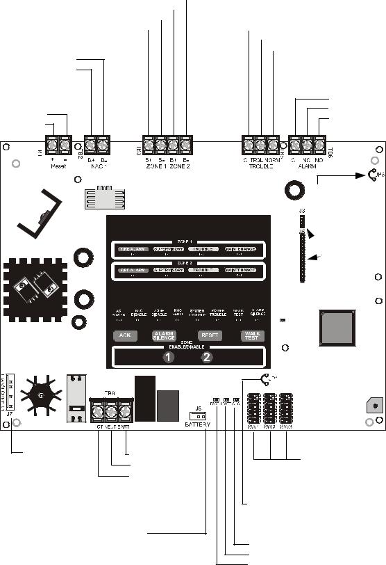
MS-2(E) Main Circuit Board |
|||||||||
IDC (4.7 KΩ, ½ watt ELR) |
|
|
|
|
|
|
|
|
|
|
|
|
(supervised, power-limited) |
|
|
|
|
|
|
|
|
|
|
Trouble Relay (fail-safe) |
|
|
Zone 2 B- |
|
|
|
|
|
|
|
|
|
|
|
|
|
|
|
|
|
|
|
|
|
|
||
|
Zone 2 B+ |
|
|
|
|
|
|
|
|
|
|
2 amps @ 30 VAC |
|
|
|
|
|
|
|
|
|
|
|
||
NAC (4.7KΩ, ½ watt ELR) |
Zone 1 B- |
|
|
|
|
|
|
|
|
|
|
(nonsupervised) |
|
|
|
|
|
|
|
|
|
|
|||
Zone 1 B+ |
|
|
|
|
|
|
|
|
|
|
Common |
|
|
|
|
|
|
|
|
|
|
|
|||
2.5A max. |
|
|
|
|
|
|
|
|
|
|
|
Trouble (Normally Open) |
|
|
|
|
|
|
|
|
|
|
|
||
(supervised, power-limited) |
|
|
|
|
|
|
|
|
|
|
|
Normal (Normally Closed) |
|
|
|
|
|
|
|
|
|
|
|
||
B- |
Alarm Relay |
|
B+ |
||
24 VDC Special Application |
2 amps @ 30 VAC |
|
(nonsupervised) |
||
Resettable Power |
||
500 mA max. (nonsupervised, |
Common |
|
power-limited) |
Normally Closed |
|
- 24 VDC |
Normally Open |
|
+ 24 VDC |
||
|
||
|
JP3 - Cut to disable |
|
|
Ground Fault |
|
|
detection (only with |
|
|
approval of AHJ) |
|
|
J3 and J5 |
|
|
4XTMF Option |
|
|
Module |
|
|
Connectors |
|
120 VAC, 2.3A or |
ms2bord.cdr |
|
|
|
||
J7 Transformer |
220/240 VAC, 1.15A |
SW1, SW2 and SW3 |
|
Earth |
|||
Programming DIP Switches |
|||
Connector |
Neutral |
||
|
|||
|
Hot |
|
|
|
(supervised, |
Module Placement Supervision (if installed) |
|
|
nonpower-limited) |
||
|
|
JP1 - cut to supervise module on J3 & J5 |
|
J8 Battery Connector |
|
||
(supervised, nonpower-limited) |
Charger Fault LED |
||
18 Amp Hour max. |
|
Battery Fault LED |
|
|
|
Earth Fault LED |
|
8 |
MS-2/MS-4 PN 51512:E 01/18/05 |

MS-4(E) Main Circuit Board
IDC (4.7 KΩ, ½ watt ELR)
NAC (4.7KΩ, ½ watt ELR)
TB2 2.5A max. per NAC (supervised, power-limited)
NAC 2 B-
NAC 2 B+
NAC 1 B-
NAC 1 B+
24 VDC Special
Application Power TB1 500 mA per circuit (nonsupervised, powerlimited)
-Reset + Reset
-Nonreset +Nonreset
TB3 (supervised, power-limited)
Zone 4 B-
Zone 4 B+
Zone 3 B-
Zone 3 B+
Zone 2 B-
Zone 2 B+
Zone 1 B-
Zone 1 B+
Trouble Relay TB5 (fail-safe)
2A @ 30 VAC (nonsupervised)
Common
Trouble (Normally Open)
Normal (Normally Closed)
Alarm Relay TB6 2A @ 30 VAC (nonsupervised)
Common Normally Closed Normally Open
Supv. Relay TB7
2A @ 30 VAC (nonsupervised)
Common Normally Closed Normally Open
TB1 |
+ |
- |
+ |
- |
TB2 |
B+ B- |
B+ |
B- |
TB3 |
B+ |
B- |
B+ |
B- |
B+ |
B- |
B+ |
B- |
C TRBL NORM |
C |
NC NOTB6 |
C |
NC |
NO TB7 |
|
|
|
|
|
|
|
|
|
|
|
|
|
|
|
|
|
|
TB5 |
|
|
|
|
|
|
Nonreset |
Reset |
|
NAC 1 |
NAC 2 |
|
ZONE 1 ZONE 2 |
ZONE 3 ZONE 4 |
TROUBLE |
|
ALARM |
|
SUPV |
|
|||||||||
|
|
|
|
|
CLASS A |
|
|
|
|
|
|
|
CONVERTER |
J1 |
|
|
|
|
|
Class A |
|||
|
|
|
|
|
|||
|
|
|
Converter Module |
|
|||
|
|
|
ZONE 1 |
|
|
|
|
FIRE ALARM |
SUPERVISORY |
TROUBLE |
MAINTENANCE |
||||
|
|
|
ZONE 2 |
|
|
|
|
FIRE ALARM |
SUPERVISORY |
TROUBLE |
MAINTENANCE |
||||
|
|
|
ZONE 3 |
|
|
|
|
FIRE ALARM |
SUPERVISORY |
TROUBLE |
MAINTENANCE |
||||
|
|
|
ZONE 4 |
|
|
|
|
FIRE ALARM |
SUPERVISORY |
TROUBLE |
MAINTENANCE |
||||
AC |
NAC |
ZONE |
NAC |
SYSTEM |
POWER |
WALK |
ALARM |
POWER |
DISABLE |
DISABLE |
FAULT |
TROUBLE |
TROUBLE TEST |
SILENCE |
|

 JP3
JP3
JP3 - Cut to disable
Ground Fault
J3 |
detection (only with |
|
|
J5 |
approval of AHJ) |
|


 J3 and J5
Option Module
Connectors
 2 TRANSFORMER
J9
 1 TRANSFORMER
J7
J7 Transformer
Connector
J9 Transformer (optional)
120 VAC, 2.3A or 220/240 VAC, 1.15A
Hot Neutral Earth
(supervised, nonpower-limited)
ACK |
ALARM |
RESET |
WALK |
|
|
SILENCE |
ZONE |
TEST |
|
1 |
ENABLE/DISABLE |
4 |
|
|
2 |
3 |
J4 |
||
|
|
|
|
|
|
J6 |
J4 and J6 |
|
|
JP2 |
|
JP1 |
|
Option Module |
|
|
|
|
|
|
|||
TB8 |
|
2 1 |
ON |
ON 2 1 |
ON 2 1 |
|
Connectors |
HOT NEUT EARTH |
BATTERY |
|
ms4bord.cdr |
||||
SW1876543 |
SW2876543 |
SW3876543 |
|
||||
|
EARTH BATT CHG |
|
|
|
|
|
|
|
J8 |
|
|
|
|
|
|
J8 Battery
Connector (supervised, nonpower-limited)
18 Amp Hour max.


 SW1, SW2 and SW3
Programming DIP Switches
Module Placement Supervision (if installed) JP1 - cut to supervise module on J3 & J5
JP2 - cut to supervise module on J4 and J6
Charger Fault LED
Battery Fault LED
Earth Fault LED
MS-2/MS-4 PN 51512:E 01/18/05 |
9 |
Product Description
SECTION 1
Product Features
Product Description
The MS-2 is a two zone FACP (Fire Alarm Control Panel) and the MS-4 is a four zone FACP. The information in this manual refers to both the MS-2 and MS-4 unless otherwise specified. These control panels provide reliable fire signaling protection for small to medium sized commercial, industrial and institutional buildings. The FACP is compatible with System Sensor’s I3 detectors which are microprocessor-based conventional smoke detectors that can transmit a maintenance trouble signal to the FACP indicating the need for cleaning and a supervisory ‘freeze’ signal when the ambient temperature falls below the detector rating (refer to System Sensor’s I3 Installation and Maintenance Instructions document I56-1800-00 for device specifications). In addition, the control panel is compatible with conventional input devices such as two-wire smoke detectors, four-wire smoke detectors, pull stations, waterflow devices, tamper switches and other normally-open contact devices. Refer to Fire•Lite Device Compatibility Document for a complete listing of compatible devices.
Outputs include one NAC (Notification Appliance Circuit) on the MS-2 and two NACs on the MS-4. Each FACP has a Form-C Alarm and Trouble relay and 24 VDC special application resettable power. In addition, the MS-4 has a Form-C Supervisory relay and a nonresettable special application power output. The FACP supervises wiring, AC voltage and battery level.
Activation of a compatible smoke detector or any normally-open fire alarm initiating device will activate audible and visual signaling devices, illuminate an indicating LED, sound the piezo sounder at the FACP, activate the FACP alarm relay and operate an optional module used to notify a remote station or initiate a auxiliary control function. The MS-2E and MS-4E offer the same features as the MS-2 and MS-4 but allows connection to 220/240 VAC.
Note: Unless otherwise specified, the terms MS-2 and MS-4 are used in this manual to refer to the MS-2 and MS-2E as well as the MS-4 and MS-4E FACPs respectively.
1.1Product Features
•Style B (Class B) IDC (Initiating Device Circuit)
one zone programmable for combination supervisory and waterflow
MS-2 - two IDCs |
|
MS-4 |
ZONE1 |
|
|
FIRE ALARM SUPERVISORY |
TROUBLE MAINTENANCE |
|
|
ZONE2 |
|
MS-4 - four IDCs |
FIRE ALARM SUPERVISORY |
TROUBLE MAINTENANCE |
ZONE3 |
|
|
FIRE ALARM SUPERVISORY |
TROUBLE MAINTENANCE |
|
ZONE4 |
|
|
FIRE ALARM SUPERVISORY |
TROUBLE MAINTENANCE |
|
• Style Y (Class B) NAC (Notification Appliance |
AC NAC ZONE NAC SYSTEM POWER WALK ALARM |
|
POWER DISABLE DISABLE FAULT TROUBLE TROUBLE TEST SILENCE |
||
|
|
|
Circuit) |
|
|
MS-2- one NACMS-4 - two NACs
•Form-C Alarm Relay
•Form-C Trouble Relay
•Form-C Supervisory Relay (MS-4 only)
•3.0 amps total system current standard for MS-2 and MS-4
•6.0 amps total system current available for MS-4 with optional second transformer
•Dress Panel DP-MS2/4
•Optional Trim Ring P/N: TR-1-R for semi-flush mounting the cabinet
10 |
MS-2/MS-4 PN 51512:E 01/18/05 |
Product Features |
Product Description |
•Control Buttons
ACK (Acknowledge)
Alarm Silence
Reset
Walktest
Zone Enable/Disable (one per zone)
•LED Indicators
Fire Alarm (one per zone)
Supervisory (one per zone)
Trouble (one per zone)
Maintenance (one per zone)
AC Power
NAC Disable
Zone Disable
NAC Fault
System Trouble
Power Trouble
Walktest
Alarm Silence
Earth Fault LED (on circuit board) lights if zero impedance between FACP and ground exist
Battery Fault (on circuit board)
Charger Fault (on circuit board)
•Piezo sounder for alarm, trouble and supervisory
•24 volt operation
•Low AC voltage sense
•Alarm Verification
•NACs Programmable for:
Silence Inhibit
Auto-Silence
Strobe Synchronization
Selective Silence (horn-strobe mute)
Temporal or Steady Signal
Silenceable or Nonsilenceable
•Automatic battery trickle charger
•Silent or audible walktest capabilities
•Optional NAC Class A converter module (MS-4 only)
•Optional 4XTMF Transmitter Module (MS-2 and MS-4)
•Optional 4XZMF Zone Relay Module (MS-4 only)
•Optional 4XLMF Module for RZA-4XF Remote LED Annunciator (MS-4 only)
MS-2/MS-4 PN 51512:E 01/18/05 |
11 |

Product Description |
Specifications |
1.2 Specifications
AC Power - TB8
MS-2/MS-4: 120 VAC, 50/60 Hz, 2.3 amps MS-2E/MS-4E: 240 VAC, 50 Hz, 1.15 amps
Wire size: minimum #14 AWG (2.0 mm2) with 600V insulation
Battery (sealed lead acid only) - J8
Maximum Charging Circuit - Normal Flat Charge: 27.6 VDC @ 0.8 amp Maximum Charger Capacity: 18 Amp Hour battery (two 7 Amp Hour batteries can be housed in the FACP cabinet. Larger batteries require a separate battery box such as the Fire•Lite BB-17F)
Initiating Device Circuits - TB3
Alarm Zones 1 & 2 (MS-2 and MS-4) Alarm Zones 3 & 4 (MS-4 only) Power-limited circuitry
Operation: All zones Style B (Class B)
Normal Operating Voltage: Nominal 20 VDC, Maximum 27 VDC Alarm Current: 15 mA minimum
Short Circuit Current: 40 mA maximum Maximum Loop Resistance: 100 ohms
End-of-Line Resistor: 4.7KΩ, 1/2 watt (Part #71252) Standby Current: 4 mA
Refer to Fire•Lite Device Compatibility Document for listed compatible devices
Notification Appliance Circuit(s) - TB21
One NAC on MS-2, two NACs on MS-4 Operation: Style Y (Class B) Power-limited Circuitry
Normal Operating Voltage: Nominal 24 VDC, Maximum 27 VDC
Maximum Signaling Current: 2.5 amps total with standard transformer. 5.0 amps total (2.5 amp maximum per NAC) with optional transformer on MS-4 only Maximum Line Impedance: 1.5 volt drop end-of-line
End-of-Line Resistor: 4.7KΩ, 1/2 watt (Part #71252)
Refer to Fire•Lite Device Compatibility Document for compatible listed devices
Form-C Relays
Trouble Relay TB5 (fail-safe) Alarm Relay TB6
Supervisory Relay TB7 (MS-4 only)
Relay Contact Ratings: 2 amps @ 30 VAC (resistive)
Resettable Special Application Power - TB1
Operating Voltage: Nominal 24 VDC
Maximum Available Current: 500 mA - appropriate for powering 4-wire smoke detectors (see note 1)
Power-limited Circuitry
Refer to Fire•Lite Device Compatibility Document for compatible listed devices
Nonresettable Special Application Power - TB1 (MS-4 only)
Operating Voltage: Nominal 24 VDC
Maximum Available Current: 500 mA (see note 1) Power-limited Circuitry
Refer to Fire•Lite Device Compatibility Document for compatible listed devices
1.Total current for resettable power and one Notification Appliance Circuit must not exceed 3.0 amps for the MS-2. Total current for nonresettable power, resettable power and two Notification Appliance Circuits must not exceed 6.0 amps for the MS-4 (requires optional second transformer)
12 |
MS-2/MS-4 PN 51512:E 01/18/05 |
Controls and Indicators |
Product Description |
1.3 Controls and Indicators
Front Panel Membrane Buttons
•Acknowledge
•Alarm Silence
•Reset
•Walktest
•Zone Enable/Disable - Zone 1
•Zone Enable/Disable - Zone 2
•Zone Enable/Disable - Zone 3 (MS-4 only)
•Zone Enable/Disable - Zone 4 (MS-4 only)
LED Indicators
•Fire Alarm Zone 1 - red LED
•Fire Alarm Zone 2 - red LED
•Fire Alarm Zone 3 - red LED (MS-4 only)
•Fire Alarm Zone 4 - red LED (MS-4 only)
•Supervisory Zone 1 - yellow LED
•Supervisory Zone 2 - yellow LED
•Supervisory Zone 3 - yellow LED (MS-4 only)
•Supervisory Zone 4 - yellow LED (MS-4 only)
•Trouble Zone 1 - yellow LED
•Trouble Zone 2 - yellow LED
•Trouble Zone 3 - yellow LED (MS-4 only)
•Trouble Zone 4 - yellow LED (MS-4 only)
•Maintenance Zone 1 - yellow LED
•Maintenance Zone 2 - yellow LED
•Maintenance Zone 3 - yellow LED (MS-4 only)
•Maintenance Zone 4 - yellow LED (MS-4 only)
•AC Power - green LED
•NAC Disable - yellow LED
•Zone Disable - yellow LED
•NAC Fault - yellow LED
•System Trouble - yellow LED
•Power Trouble - yellow LED
•Walktest - yellow LED
•Alarm Silence - yellow LED
•Earth Fault - yellow LED (on main circuit board) lights if zero impedance between FACP and ground exists
•Battery Fault - yellow LED (on main circuit board)
•Charger Fault - yellow LED (on main circuit board)
MS-2/MS-4 PN 51512:E 01/18/05 |
13 |
Product Description |
Circuits |
Local Piezo Sounder
A piezo sounder provides separate and distinct sounds for alarm, trouble, maintenance and supervisory conditions as follows:
•Alarm - on steady
•Trouble - pulse 1 second on and 1 second off
•Maintenance - pulse ½ second on and ½ second off
•Supervisory - pulse ½ second on and ½ second off
1.4 Circuits
Input Circuits
Two input IDCs (Initiating Device Circuits) on the MS-2 and four IDCs on the MS-4 provide Style B (Class B) configurations. All IDCs accept I3 detectors as well as conventional two-wire smoke detectors, four-wire smoke detectors and normally-open contact devices.
Output Circuits
•24 VDC resettable special application power output - 500 mA
•24 VDC nonresettable special application power output (MS-4 only) - 500 mA
•24 volt battery charger (up to 18 Amp Hour batteries)
Notification Appliance Circuits
One NAC (Notification Appliance Circuit) Style Y (Class B) on the MS-2
Two NACs Style Y (Class B) on the MS-4
Relays
Alarm Relay
Trouble Relay (fail-safe)
Supervisory Relay (MS-4 only)
Form-C contacts rated 2.0 amps @ 30 VAC (resistive)
1.5 Components
Main Circuit Board
The main circuit board contains the system’s CPU, power supply, other primary components and wiring interface connectors. Optional modules plug in and are mounted to the main circuit board.
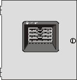
Cabinet
The backbox measures 14.5” (36.8 cm) x 15.218” (38.65 cm) x 2.875” (7.3 cm) and provides space for two batteries (up to 7 Amp Hours). Also included is a dress panel which mounts inside the cabinet.
Transformer Assembly
One 100VA transformer is provided standard with the FACP. An optional second 100VA transformer is available for the MS-4 to provide maximum accessory power.
Batteries
The cabinet provides space for two 7 Amp Hour batteries (larger batteries up to 18 Amp Hour, require use of a UL listed battery box such as the BB-17F). Batteries must be ordered separately.
14 |
MS-2/MS-4 PN 51512:E 01/18/05 |
Optional Modules and Accessories |
Product Description |
1.6 Optional Modules and Accessories
CAC-4 Class A Converter Module (MS-4 only)
The CAC-4 Module can be used to convert the Style B (Class B) Initiating Device
Circuits to Style D (Class A) and Style Y (Class B) Notification Appliance Circuits to
Style Z (Class A). The module connects to J1 on the MS-4 main circuit board.
4XTMF Transmitter Module (MS-2 and MS-4)
The 4XTMF provides a supervised output for local energy municipal box transmitter and alarm and trouble reverse polarity. It includes a disable switch and disable trouble LED. A module jumper option allows the reverse polarity circuit to open with a system trouble condition if no alarm condition exists. The 4XTMF mounts to the MS-2 main circuit board option module connectors J3 & J5 or the MS-4 main circuit board, occupying one of the two sets of option module connectors J3 & J5 or J4 & J6.
4XLMF LED Interface Module (MS-4 only)
The LED Interface Module supports the RZA-4XF Remote Annunciator module. Annunciator wiring is supervised for open conditions by this module. The 4XLMF mounts to the MS-4 main circuit board option module connectors J3 and J5 only.
RZA-4XF Remote Annunciator (MS-4 only)
The Remote Annunciator mounts on a standard single-gang electrical box and provides
LED indication of the following:
•Alarm Zone 1 (red LED)
•Alarm Zone 2 (red LED)
•Alarm Zone 3 (red LED)
•Alarm Zone 4 (red LED)
•System Trouble (yellow LED)
A Local Trouble Sounder and Silence Switch are also provided. All LED wiring is supervised for open conditions. Any open condition will cause the System Trouble LED to illuminate. Slide-in paper labels permit an easy change of zone information.
Note: The RZA-4XF Remote Annunciator requires the use of the LED Interface Module (4XLMF).
4XZMF Zone Relay Module (MS-4 only)
The Zone Relay Module provides Form-C relay contacts for the following:
•Alarm Zone 1
•Alarm Zone 2
•Alarm Zone 3
•Alarm Zone 4
•System Alarm
•System Trouble
As a jumper option, the first four relays described above can be made silenceable. The 4XZMF mounts to the MS-4 main circuit board, occupying one of the two sets of option module connectors.
Dress Panel DP-MS2/4
A dress panel DP-MS2/4 is included. The dress panel restricts access to the system wiring while allowing access to the membrane switch panel.
MS-2/MS-4 PN 51512:E 01/18/05 |
15 |
Product Description |
Optional Modules and Accessories |
Battery Box
The Fire•Lite BB-17F battery box may be used to house two batteries greater than 7 Amp Hour to a maximum of 18 Amp Hour. The battery box mounts directly below the control panel cabinet, centered to the main circuit board. The BB-17F is red and is provided with knockouts.
411 and 411UD Digital Alarm Communicator/Transmitter
The three input/channel 411 and the four input/channel 411UD are dual line, digital alarm communicator/transmitters which can be used as slave communicators with the MS-4 FACP. The inputs/channels are compatible with normally open relay contacts, require ELRs (End-of-Line Resistors), are supervised and are fully programmable. The communicators interface with the public switched telephone network and are compatible with most central station receivers. Power supplied must be 12 or 24 volts, filtered and nonresettable. The communicators are mounted in a small metal enclosure, providing a variety of mounting options. Refer to the 411 or 411UD manual for additional information.
16 |
MS-2/MS-4 PN 51512:E 01/18/05 |
Backbox Mounting
SECTION 2
Installation
Installation
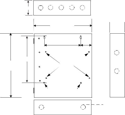
The cabinet can be surface mounted or semi-flush mounted using the optional Trim Ring P/N: TR-1-R. The door is removable during the installation period by opening and lifting if off the hinges. The cabinet mounts using two key slots at the top of the backbox and two additional 0.250” diameter holes located at the bottom.
Carefully unpack the system and check for shipping damage. Select a location for the cabinet that is in a clean, dry, vibration-free area where extreme temperatures are not encountered. The area should be readily accessible with sufficient room to easily install and maintain the control panel. Locate the top of the cabinet approximately five feet above the floor with the hinge mounting on the left.
Determine the number of conductors required for the devices to be installed and determine the appropriate knockouts. All wiring must be in accordance with the National and/or Local codes for fire alarm systems and power supplies.
2.1Backbox Mounting
1.Mark and predrill holes for the top two keyhole mounting bolts
2.Install two upper fasteners in the wall with the screw heads protruding approximately ¼”
3.Using the upper keyholes, mount the backbox over the two screws
4.Mark the lower two holes, remove the backbox from the wall and drill the mounting holes
5.Mount the backbox, install the remaining fasteners and tighten all screws
Top
2.875” (7.3 cm)
|
Backbox = 14.5” |
|
|
(36.8 cm) |
|
0.75”(1.9 cm) |
|
|
|
|
2.7” |
|
9.1” (23.1 cm) |
(6.86cm) |
10.375” |
|
|
Height=15.000” (26.35 cm) |
Pem Studs |
|
(38.10 cm) |
|
|
 Backbox Mounting Holes
Depth = 3.000”
(7.62 cm)
ms2-4cab.cdr
Bottom |
|
|
|
|
|
|
|
1.125” (2.868 cm) |
||
|
|
|
|
|
|
|
|
|
|
|
Figure 2.1 Backbox Mounting Dimensions
MS-2/MS-4 PN 51512:E 01/18/05 |
17 |
 Loading...