


Control Panels
D9412GV4/D7412GV4 v2.00
en Installation and System Reference Guide

D9412GV4/D7412GV4 v2.00 | Installation and System Reference Guide | Certifications and Approvals
Certifications and Approvals |
equivalence number (REN). If requested, this |
|
information must be provided to the telephone |
||
The D9412GV4/D7412GV4 v2.00 Literature Pack |
company. |
|
The D9412GV4 and D7412GV4 Control Panels are |
||
includes an Approved Applications chapter in this |
||
guide. Refer to this chapter for additional |
registered for connection to the public telephone |
|
guidelines on installing the control panels in |
network using an RJ38X or RJ31X jack. |
|
Underwriters Laboratories Inc. (UL) and fire- |
The REN is used to determine the number of |
|
specific applications. |
devices that can be connected to the telephone |
|
Listings and Approvals |
line. Excessive RENs on the telephone line may |
|
result in the devices not ringing in response to an |
||
|
||
UL |
incoming call. In most, but not all areas, the sum |
|
of the RENs should not exceed five. To be certain |
||
The D9412GV4 and D7412GV4 are listed as UL |
of the number of devices that may be connected |
|
864 Commercial Fire control panels. The |
to the line, as determined by the RENs, contact |
|
D9412GV4 and D7412GV4 are also UL Listed for |
the telephone company to determine the |
|
Central Station, Local, Auxiliary, Proprietary, and |
maximum REN for the calling area. |
|
Household Fire Alarm, and Central Station, Local, |
If you experience trouble with the control panel, |
|
Police Station Connect, Holdup, Household |
please contact Bosch Security Systems Customer |
|
Burglar Alarm and Encrypted line Security when |
Service for repair and warranty information. If the |
|
communicating via a network. |
trouble is causing harm to the telephone |
|
cUL |
network, the telephone company might request |
|
The D9412GV4 and D7412GV4 are cUL listed for |
that the equipment be removed from the network |
|
until the problem is resolved. User repairs must |
||
Local Burglar Alarms, Signal Receiving Centre and |
||
not be made, and doing so will void the user’s |
||
Premise Alarm, Residential Fire, Household |
||
warranty. |
||
Burglar, Propriety Burglar, and Digital Apparatus. |
||
If the D9412GV4, or D7412GV4 Control Panels |
||
Department of Defense (DOD) |
||
causes harm to the telephone network, the |
||
The D9412GV4/D7412GV4 was granted approval |
||
telephone company attempts to notify you in |
||
for Department of Defense (DoD) installations in |
advance. If advance notice is not practical, the |
|
Sensitive Compartmented Information Facilities |
telephone company notifies you as soon as |
|
(SCIF). |
possible. Also, you will be advised of your right to |
|
Federal Communications Commission |
file a complaint with the FCC if you believe it is |
|
(FCC) Rules |
necessary. |
|
Part 15 |
The telephone company might make changes in |
|
its facilities, equipment, operations, or |
||
This equipment was tested and found to comply |
||
procedures that could affect the operation of the |
||
with the limits for a Class B digital device, |
||
equipment. If this happens, the telephone |
||
pursuant to Part 15 of the FCC rules. These limits |
||
company provides advance notice in order for the |
||
are designed to provide reasonable protection |
||
necessary modifications to be made, resulting in |
||
against harmful interference when the equipment |
||
uninterrupted service. |
||
is operated in a commercial environment. |
||
This equipment cannot be used on public coin |
||
This equipment generates, uses, and can radiate |
||
service provided by the telephone company. |
||
radio frequency energy; and if not installed and |
||
Connection to Party Line service is subject to |
||
used according to the instructions, can cause |
||
state tariffs. (Contact your state public utilities |
||
harmful interference to radio communications. |
||
commission for information.) |
||
Operation of this equipment in a residential area |
||
FCC Registration Number: |
||
is likely to cause harmful interference, in which |
||
US:ESVOT00BD9412GV3 |
||
case the user is required to correct the |
||
Service Center in USA: |
||
interference at his or her own expense. |
||
Bosch ST Service Center |
||
Part 68 |
||
8601 East Cornhusker Hwy |
||
This equipment complies with Part 68 of FCC |
Dock B |
|
rules. A label contains, among other information, |
Lincoln, NE 68507 - 9702 USA |
|
the FCC registration number and ringer |
Ringer Equivalence: 0.0B |
|
|
|
|
Bosch Security Systems, Inc. | 2/13 | F01U265457-03 |
2 |
|
D9412GV4/D7412GV4 v2.00 |
| Installation and System Reference Guide | Contents |
||||
Contents |
|
4.7 |
Updating Control Panel Firmware .... |
20 |
||
|
4.8 |
Programming the Control Panel ..... |
20 |
|||
Federal Communications Commission (FCC) |
2 |
4.9 |
Installing the Point Chart Label...... |
20 |
||
|
Rules ........................... |
4.10 |
Testing the System ............... |
20 |
||
1.0 |
Introduction ...................... |
7 |
4.11 |
Service Walk Test ................ |
21 |
|
2.0 |
Lightning Strikes .................. |
9 |
5.0 |
Power Supply.................... |
24 |
|
2.1 |
Effects .......................... |
9 |
5.1 |
Primary Power Terminals 1 and 2 .... |
24 |
|
2.2 |
Precautions during Installation |
9 |
5.1.1 |
Primary (AC) Power Circuit................... |
24 |
|
5.1.2 |
Installing the Transformer |
24 |
||||
3.0 |
Overview |
10 |
||||
5.2 |
Secondary Power Terminals |
24 |
||||
3.1 |
Configuration and Parts |
10 |
||||
|
............ |
5.2.1 |
Secondary (DC) Power |
24 |
||
3.1.1 |
Parts List |
11 |
||||
5.2.2 |
Installing the Battery |
25 |
||||
3.1.2 |
Parts Available by Separate Order |
11 |
||||
5.2.3 |
Replacing the Battery |
26 |
||||
3.2 |
Accessories |
12 |
||||
5.2.4 |
Battery Supervision |
27 |
||||
3.3 |
Features in the GV4 Series Control Panels |
|||||
5.2.5 |
Battery Charging Circuit Float Charge |
27 |
||||
|
............................... |
13 |
||||
3.3.1 |
SDI Interconnect Wiring ........................ |
13 |
5.2.6 |
Battery Discharge and Recharge Schedule |
||
3.3.2 |
Tip and Ring Posts................................. |
13 |
|
.............................................................. |
28 |
|
3.3.3 |
Telephone Line Sniff.............................. |
13 |
6.0 |
Power Outputs................... |
30 |
|
3.3.4 |
Points .................................................... |
14 |
6.1 |
Circuit Protection ................ |
30 |
|
3.3.5 |
Areas and Accounts ............................... |
14 |
6.2 |
Total Available Power ............. |
30 |
|
3.3.6 |
Digital Communicator............................ |
14 |
6.3 |
Continuous Power Output Terminals 3, 8, |
||
3.3.7 |
Keypads ................................................. |
14 |
|
24, and 32 ...................... |
30 |
|
3.3.8 |
Keyswitch .............................................. |
15 |
6.4 |
Programmable Power Output Terminals 6, |
||
3.3.9 |
Access Control....................................... |
15 |
|
7, and 8 ........................ |
30 |
|
3.3.10 |
Event Memory |
15 |
6.4.1 |
Programming ......................................... |
31 |
|
6.4.2 |
Terminals 6 and 7 |
31 |
||||
3.3.11 |
Event Log |
15 |
||||
6.4.3 |
Fire System Power Formula |
31 |
||||
3.3.12 |
Ground Fault Detection |
15 |
||||
6.4.4 |
Terminal 8 |
31 |
||||
3.3.13 |
Ground Fault Detection Added Feature 15 |
|||||
7.0 |
Telephone Connections |
32 |
||||
3.3.14 |
Conettix Functions ................................ |
16 |
||||
3.3.15 |
Programming ......................................... |
16 |
7.1 |
Registration ..................... |
32 |
|
3.3.16 |
Dual Authentication ............................... |
16 |
7.2 |
Notification ..................... |
32 |
|
3.3.17 |
Other Features ...................................... |
16 |
7.3 |
Location........................ |
32 |
|
4.0 |
Installation ...................... |
17 |
7.4 |
Telephone Cord Connection ........ |
32 |
|
4.1 |
Installation Preparation ............ |
17 |
7.5 |
Phone LED (Red)................. |
33 |
|
4.2 |
Enclosure Options ................ |
17 |
7.6 |
Operation Monitor LED (Green) ..... |
33 |
|
4.3 |
Mounting Enclosure............... |
17 |
7.7 |
Dialing Format ................... |
33 |
|
4.4 |
Installing the Control Panel ......... |
18 |
7.8 |
Telephone Line Monitor ........... |
33 |
|
4.5 |
Connecting Earth Ground .......... |
18 |
7.9 |
Called Party Disconnect ........... |
34 |
|
4.5.1 |
Terminal 10............................................ |
18 |
7.10 |
Communication Failure ............ |
34 |
|
4.5.2 |
Ground Fault Detect Enable .................. |
18 |
7.11 |
D928 Dual Phone Line Switcher ..... |
34 |
|
4.5.3 |
Enabling Ground Fault Detection .......... |
18 |
7.11.1 |
Description............................................ |
34 |
|
4.5.4 |
Ground Fault Specifications .................. |
18 |
7.11.2 |
Operation .............................................. |
34 |
|
4.5.5 |
Locking the Reset Pin............................ |
19 |
7.11.3 |
Installing the D928 ................................ |
35 |
|
4.6 |
Completing the Installation ......... |
19 |
7.11.4 |
D928 Status LEDs ................................. |
35 |
|
4.6.1 |
Charging the Battery.............................. |
19 |
8.0 |
On-Board Points ................. |
37 |
|
4.6.2 |
Installing and Wiring Detection Devices 19 |
8.1 |
Terminals 11 to 22 Description ...... |
37 |
||
4.6.3 |
Installing Modules and Outputs............. |
20 |
8.2 |
Point Sensor Loops ............... |
37 |
|
4.6.4 |
Connecting the On-board Points and |
|
8.3 |
Point Parameters................. |
37 |
|
|
Keypads ................................................. |
20 |
8.4 |
Point Response Time.............. |
38 |
|
4.6.5 |
Powering Up .......................................... |
20 |
|
|
|
|
Bosch Security Systems, Inc. | 2/13 | F01U265457-03 |
|
|
3 |
|||
|
D9412GV4/D7412GV4 v2.00 |
| Installation and System Reference Guide | Contents |
||||
8.5 |
Wiring Information for Installations Using |
11.3 |
D279A Independent Zone Control.... |
62 |
||
|
the Rothenbuhler 5110/4001-42 High |
38 |
11.4 |
Keyswitch ...................... |
62 |
|
|
Security Bell .................... |
11.4.1 |
Description............................................ |
62 |
||
9.0 |
Off-Board Points ................. |
41 |
11.4.2 |
Programming ......................................... |
62 |
|
9.1 |
Zonex Buses .................... |
41 |
11.4.3 |
Installation............................................. |
62 |
|
9.1.1 |
POPIT Modules ...................................... |
41 |
11.4.4 |
Operation .............................................. |
62 |
|
9.1.2 |
POPEX Modules..................................... |
41 |
12.0 SDI Devices |
64 |
||
9.1.3 |
Missing Conditions |
41 |
||||
12.1 |
Description |
64 |
||||
9.1.4 |
Control Panel Responses to Missing Point |
|||||
12.2 |
Installation |
64 |
||||
|
Conditions |
41 |
||||
|
12.2.1 |
Open Wire Trouble on SDI |
64 |
|||
9.2 |
D8125 and D9127 POPIT Modules |
41 |
||||
12.3 |
D9210C Access Control Interface Module |
|||||
9.3 |
Installing the D8125 POPEX Module .. |
43 |
|
.............................. |
64 |
|
9.3.1 |
Mounting................................................ |
43 |
12.3.1 |
Access ................................................... |
64 |
|
9.3.2 |
Wiring the D8125 to the Control Panel .43 |
12.3.2 |
Switch Settings ..................................... |
64 |
||
9.3.3 |
Wiring POPITs to the Data Expansion |
|
12.4 |
SDI Addresses 88 and 92 .......... |
65 |
|
|
Loop ...................................................... |
44 |
12.4.1 |
Local RPS Programming........................ |
65 |
|
9.3.4 |
Wiring Data Expansion Loops to POPEX |
|
12.5 |
SDI Network Interface Modules ..... 65 |
||
|
Modules |
44 |
||||
|
12.5.1 |
Address Settings |
66 |
|||
9.3.5 |
POPIT Sensor Loops |
44 |
||||
12.5.2 |
Supervision |
66 |
||||
9.3.6 |
POPIT Module Point Assignments |
45 |
||||
13.0 SDI2 Devices |
67 |
|||||
9.3.7 |
Program Record Sheet |
45 |
||||
13.1 |
Description |
67 |
||||
9.3.8 |
POPIT Labels |
45 |
||||
13.2 |
Installation |
67 |
||||
9.4 |
D8128D OctoPOPIT Module |
46 |
||||
13.2.1 |
Open Wire Trouble on SDI2 .................. |
67 |
||||
9.4.1 |
Description ............................................ |
46 |
13.3 |
B208 Octo-input Module |
67 |
|
9.4.2 |
Listings |
46 |
||||
13.3.1 |
Address Settings |
67 |
||||
9.4.3 |
Installation |
46 |
||||
13.3.2 |
Supervision |
68 |
||||
9.4.4 |
Setting the OctoPOPIT Switches |
47 |
||||
13.4 |
B308 Octo-output Module |
68 |
||||
9.4.5 |
Mounting OctoPOPITs |
47 |
||||
13.4.1 |
Address Settings |
68 |
||||
9.4.6 |
Wiring OctoPOPITs |
48 |
||||
13.4.2 |
Supervision |
69 |
||||
9.4.7 |
OctoPOPIT Sensor Loops |
52 |
||||
13.5 |
B426 Ethernet Communication Module 69 |
|||||
9.5 |
Testing Off-Board Points |
53 |
||||
13.5.1 |
Address and Emulation Settings ........... |
69 |
||||
9.6 |
SDI2 Octo-input Point Modules...... |
53 |
13.5.2 |
Supervision............................................ |
69 |
|
9.7 |
Extra Point Events ................ |
53 |
13.5.3 |
Local RPS Programming........................ |
69 |
|
10.0 Off-Board Outputs .................. |
55 |
13.5.4 |
Ethernet Communications Module Faults |
|||
10.1 |
D8129 OctoRelay................. |
55 |
|
.............................................................. |
69 |
|
10.1.1 |
Configuring the D8129 OctoRelay ......... |
57 |
13.6 |
B420 Ethernet Communication Module 70 |
||
10.1.2 |
Relay Outputs |
57 |
||||
13.6.1 |
Address and Emulation Settings ........... |
70 |
||||
10.1.3 |
Installation............................................. |
57 |
13.6.2 |
Supervision............................................ |
70 |
|
10.1.4 |
Wiring Connections ............................... |
57 |
13.6.2 |
Local RPS Programming........................ |
70 |
|
10.2 |
D811 Arm Status Relay Module ...... |
58 |
13.6.3 |
Ethernet Communications Module Faults |
||
10.2.1 |
Relay Output.......................................... |
58 |
|
.............................................................. |
70 |
|
10.2.2 |
Installation............................................. |
58 |
13.7 |
B520 Auxiliary Power Supply Module . 71 |
||
10.2.3 |
Wiring Connections ............................... |
58 |
13.7.1 |
Address Settings ................................... |
71 |
|
10.3 |
SDI2 Octo-output Relay Modules .... 58 |
13.7.2 |
Supervision............................................ |
71 |
||
11.0 Arming Devices..................... |
60 |
13.7.3 |
Auxiliary Power Supply Faults ............... |
71 |
||
11.1 |
Description ..................... |
60 |
13.8 |
B810 wireless receiver ............ |
72 |
|
11.2 |
SDI/SDI2 Bus Terminals 29 to 36 .... |
60 |
13.8.1 |
Supervision............................................ |
72 |
|
11.2.1 |
Shortcuts and Custom Functions .......... |
60 |
13.8.2 |
Wireless Receiver Faults........................ |
72 |
|
11.2.2 |
Assigning an Address for the Keypad .... |
61 |
13.8.3 Wireless Repeater Faults........................ |
72 |
||
11.2.3 |
Installation............................................. |
61 |
13.9 |
B820 SDI2 Inovonics Interface Module |
72 |
|
|
|
|
|
|||
Bosch Security Systems, Inc. | 2/13 | F01U265457-03 |
|
|
4 |
|||

D9412GV4/D7412GV4 v2.00 | Installation and System Reference Guide | Contents
13.9.1 |
Supervision............................................ |
72 |
13.9.2 |
Wireless Receiver Faults........................ |
72 |
13.9.3 |
Wireless Repeater Faults...................... |
73 |
13.10 |
B920 Two-lined Alphanumeric Keypad |
73 |
13.10.1 LCD Backlit Settings............................. |
73 |
|
13.10.2 LCD Power Up Status........................... |
73 |
|
13.10.3 LCD Communication Status ................. |
73 |
|
13.11 |
B930 ATM Style Alphanumeric Keypad |
73 |
13.11.1 LCD Backlit Settings............................. |
74 |
|
13.11.2 LCD Power Up Status........................... |
74 |
|
13.11.3 LCD Communication Status ................. |
74 |
|
14.0Installer Menu .... Error! Bookmark not defined.
14.1RPS Access Reports . Error! Bookmark not defined.
15.0 |
Accessory Connector ................ |
75 |
16.0 |
Faceplates ........................ |
76 |
16.1D9412GV4/D7412GV4 v2.00 Faceplate 76
17.0 |
Specifications...................... |
77 |
|
17.1 |
|
Control Panel Power Supply ........ |
77 |
17.2 |
|
B520 Power Supply ............... |
78 |
17.3 |
|
Control panel Terminal Wiring....... |
79 |
18.0 |
Approved Applications ............... |
81 |
|
18.1 |
|
Optional Compatible Equipment ..... |
81 |
18.2 |
|
Burglary Applications.............. |
81 |
18.3 |
|
Bank Safe and Vault Applications .... |
81 |
18.3.1 |
Control Panel Enclosure Requirements.81 |
||
18.3.2 |
Battery Connections.............................. |
81 |
|
18.3.3 |
Bell Requirements ................................. |
81 |
|
18.3.4 |
System Configuration Requirements..... |
81 |
|
18.3.5 |
Exit Delay............................................... |
82 |
|
18.3.6 |
Equipment Requirements ...................... |
82 |
|
18.4 |
|
Fire Applications ................. |
82 |
18.4.1 |
Four-Wire Smoke Detectors .................. |
82 |
|
18.4.2 |
Two-Wire Smoke Detectors ................... |
83 |
|
18.4.3 |
Two-Wire Smoke Detector Specifications |
||
|
|
............................................................... |
83 |
18.4.4 |
NFPA Style A (Class “B”) Circuit ............ |
83 |
|
18.4.5 |
Other Devices ........................................ |
83 |
|
18.4.6 |
UL Listed Two-Wire Smoke Detectors |
|
|
|
|
Compatible with the D125B .................. |
84 |
18.4.7UL Listed Synchronization (Sync) Modules and Strobes Compatible with the
|
D9412GV4/D7412GV4 ........................... |
86 |
18.5 |
Enclosures ...................... |
91 |
18.5.1 |
D8103 Enclosure ................................... |
91 |
18.5.2 |
D8108A Enclosure ................................. |
91 |
18.5.3 |
D8109 Red Fire Enclosure ..................... |
91 |
19.0 Keypad Installer Menu ............... |
92 |
|
19.1 |
[1] Program Menu ................ |
95 |
19.1.1 |
[1] Reporting > [1] Phone Menu |
|
|
Parameters ............................................ |
95 |
19.1.2 |
[1] Reporting > [2] Network Menu |
|
|
Parameters ............................................ |
96 |
19.1.3 |
[1] Reporting > [3] Routing Menu |
|
|
Parameters ............................................ |
99 |
19.1.4 |
[2] IP Module > [1] B42x (1) or [2] B42x |
|
|
(2) Module Parameters ....................... |
101 |
19.1.5 |
[2] IP Module > [1] B42x (1) or [2] B42x |
|
|
(2) [2] Address Parameters ................ |
102 |
19.1.6 |
[2] IP Module > [1] B42x (1) or [2] B42x |
|
|
(2) [3] DNS Parameters ...................... |
104 |
19.1.7 |
[3] RPS > [1] RPS Passcode Menu |
|
|
Parameters .......................................... |
105 |
19.1.8 [3] RPS > [2] RPS Phone Number Menu |
||
|
Parameters .......................................... |
106 |
19.1.9 |
[3] RPS > [3] RPS IP Address Menu |
|
|
Parameters .......................................... |
106 |
19.1.10 [3] RPS > [4] RPS Port Number Menu |
|
|
|
Parameters .......................................... |
107 |
19.1.11 [4] Area Options Menu Parameters ... |
107 |
|
19.1.12 [5] Keypad > [1] Scope Menu Parameters |
||
|
............................................................ |
109 |
19.1.13 [6] Users Menu Parameters ............... |
110 |
|
19.1.14 [7] Points Menu Parameters .............. |
112 |
|
19.1.15 [8] Disable Programming Menu |
|
|
|
Parameters .......................................... |
119 |
19.2 |
[2] Wireless Menu ............... |
120 |
19.2.1 [1] Points > [1] Enroll Point RFID Menu |
||
|
Parameters .......................................... |
120 |
19.2.2 [1] Points > [2] Replace Point RFID Menu |
||
|
Parameters .......................................... |
120 |
19.2.3 [1] Points > [3] Remove Point RFID Menu |
||
|
Parameters .......................................... |
121 |
19.2.4 [2] Repeaters > [1] Add Repeater Menu |
||
|
Parameters .......................................... |
121 |
19.2.5 [2] Repeaters > [2] Replace Repeater |
|
|
|
Menu Parameters ................................ |
122 |
19.2.6 [2] Repeaters > [2] Remove Repeater |
|
|
|
Menu Parameters ................................ |
123 |
19.2.7 [3] Diagnostics > [1] RF Points ............ |
123 |
|
19.2.8 [3] Diagnostics > [2] RF Repeaters...... |
124 |
|
19.3 |
[3] Network Menu ............... |
126 |
19.3.1 [1] B42x > [1] Settings Menu Parameters |
||
|
............................................................ |
126 |
19.4 |
[4] Srvc Byp Menu............... |
127 |
19.5 |
[5] Versions Menu ............... |
127 |
20.0 |
UL/NFPA Compliant Installations ... |
128 |
20.1 Required Components ............. |
128 |
|
20.2 Installing Combination Fire and Intrusion |
|
|
|
Alarm Systems.................. |
128 |
Bosch Security Systems, Inc. | 2/13 | F01U265457-03 |
5 |

D9412GV4/D7412GV4 v2.00 | Installation and System Reference Guide | Contents
20.2.1 SDI Bus Devices................................... |
128 |
|
20.2.2 Zonex Bus Devices............................... |
128 |
|
20.2.3 SDI2 Bus Devices................................. |
129 |
|
21.0 |
Compatible UL Listed Components.. |
130 |
22.0 Current Ratings Charts.............. |
131 |
|
22.1 D8125MUX....................... |
131 |
|
22.2 Standby Battery Calculations ........ |
131 |
|
23.0 NFPA 72 Fire Alarm Applications ...... |
134 |
|
23.1Household Burglary and Commercial
|
Burglary ....................... |
134 |
23.2 |
Bank Safe and Vault.............. |
134 |
23.3 |
Standby Battery Calculation ....... |
134 |
23.4 |
Central Station or Local Systems ... |
135 |
23.5 |
Remote Station or Auxiliary Systems |
135 |
23.6Household Fire Warning Equipment . 136
23.7 |
UL 609 ........................ |
136 |
|
23.8 |
UL 365 ........................ |
136 |
|
23.9 |
UL 636 ........................ |
137 |
|
23.10 |
ULC S304 Requirements .......... |
137 |
|
Appendix A: System Wiring Diagrams....... |
138 |
||
A.1 |
Power Supply Side System Wiring .. 138 |
||
A.2 |
Input Points and Peripheral Devices |
|
|
|
Wiring Diagrams ................ |
139 |
|
A.3 |
SDI and Zonex Devices System Wiring 140 |
||
A.4 |
SDI2 Bus Wiring Recommendations . 143 |
||
Appendix B: Point Address Charts ......... |
145 |
||
B.1 |
Zonex 1 Points.................. |
145 |
|
B.2 |
SDI2 Points .................... |
146 |
|
|
|
Figures |
|
Figure 1: |
System Configuration............ |
10 |
|
Figure 2: |
Enclosure Mounting............ |
17 |
|
Figure 3: |
Enabling Ground Fault Detection . 18 |
||
Figure 4: |
Reset Pin .................... |
19 |
|
Figure 5: |
Service Walk Test Flow Chart Example |
||
|
|
............................ |
23 |
Figure 6: |
Battery Terminals ............. |
25 |
|
Figure 7: |
Non-Power-Limited Wiring....... |
26 |
|
Figure 8: |
Charging and Battery LEDs ...... |
27 |
|
Figure 9: |
RJ31X/RJ38X Wiring (RJ31X shown) |
||
|
|
............................ |
32 |
Figure 10: Phone Connector, Phone LED, and |
|
||
|
|
Operation Monitor LED Locations. 33 |
|
Figure 11: |
D928 Dual Phone Line Switcher .... |
35 |
|
Figure 12: On-board Point Sensor Loop Wiring 37 |
|||
Figure 13: Rothenbuhler 5110/4001-42 High |
|
||
|
|
Security Bell Wiring Configuration |
39 |
Figure 14: Wiring the Rothenbuhler 5110/4001- |
|||
|
|
42 High Security Bell to the Control |
|
|
|
Panel ....................... |
40 |
Figure 15: Connecting the D8125 POPEX to the |
||
|
D9412GV4 Control Panel ....... |
42 |
Figure 16: Connecting the D8125 POPEX to the |
||
|
D7412GV4 Control Panel ....... |
43 |
Figure 17: D8128D OctoPOPIT Layout...... |
46 |
|
Figure 18: Connecting D8128D OctoPOPITs to |
||
|
the D9412GV4 ................ |
49 |
Figure 19: Connecting D8128D OctoPOPITs to |
||
|
the D7412GV4 ................ |
50 |
Figure 20: Wiring Multiple D8128Ds Using |
|
|
|
Interconnect Wiring............ |
52 |
Figure 21: D8128D OctoPOPIT Sensor Loops |
52 |
|
Figure 22: D8129 Connections to the D9412GV4 |
||
|
........................... |
56 |
Figure 23: D8129 Connections to the D7412GV4 |
||
|
........................... |
56 |
Figure 24: D811 Arm Status Relay Module Wiring |
||
|
to the D9412GV4.............. |
59 |
Figure 25: D811 Arm Status Relay Module Wiring |
||
|
to the D7412GV4.............. |
59 |
Figure 26: External Power to SDI2 Devices .. |
62 |
|
Figure 27: Keyswitch Wiring .............. |
63 |
|
Figure 28: DX4020 DIP Switch Settings ..... |
66 |
|
Figure 29: |
B208 Switches Set to Address 9.. |
67 |
Figure 30: |
B308 Switches Set to Address 9.. |
68 |
Figure 31: |
B426 Switch Set to Address 1 ... 69 |
|
Figure 32: |
B420 Switch Set to Address 1 ... 70 |
|
Figure 33: |
B520 Switch Set to Address 2 ... 71 |
|
Figure 34: |
B810 Switch Set to Address 1 ... 72 |
|
Figure 35: |
B820 Switch Set to Address 1 ... 72 |
|
Figure 36: Accessory Connection on D9412GV4 |
||
|
and D7412GV4 ............... |
75 |
Figure 37: D9412GV4/D7412GV4 v2.00 Faceplate |
||
|
........................... |
76 |
Figure 38: Keypad Installer menu tree ...... |
94 |
|
Figure 39: D9412GV4/D7412GV4 v2.00 Power |
||
|
Supply Side System Wiring (Power |
|
|
and Phone) ................. |
138 |
Figure 40: D9412GV4/D7412GV4 v2.00 Input |
||
|
Points and Peripheral Devices System |
|
|
Wiring ..................... |
139 |
Figure 41: D9412GV4 SDI and Zonex Devices |
|
|
|
System Wiring ............... |
140 |
Figure 42: D7412GV4 SDI and Zonex Devices |
|
|
|
System Wiring ............... |
141 |
Figure 43: D9412GV4/D7412GV4 SDI2 Devices |
||
|
System Wiring ............... |
142 |
Figure 44: SDI2 Bus Wiring ............. |
143 |
|
Bosch Security Systems, Inc. | 2/13 | F01U265457-03 |
6 |

D9412GV4/D7412GV4 v2.00 | Installation and System Reference Guide | |
1.0 |
Introduction |
|
|
|
1.0 Introduction
This manual addresses the operation and installation of the D9412GV4/D7412GV4 v2.00 Control Panels. Throughout this guide, the words “control panel” refer to all control panels (D9412GV4 and D7412GV4). Table 2 on page 11 provides an overview of the differences in the control panels.
To obtain any of the documents in Table 1, contact Bosch Security Systems, Inc. Customer Service at (800) 289-0096 and request the documentation by its corresponding part number.
Table 1: |
Related Documentation |
|
|
|
|
|
|
Product Type |
Name of Documentation |
Part Number |
|
|
|
|
|
Control Panels |
Control Panels (D9412GV4/D7412GV4 v2.00) Release Notes |
F01U2654611 |
|
|
|
Control Panels (D9412GV4/D7412GV4 v2.00) Installation and System Reference |
F01U2654572 |
|
|
Guide (this document) |
|
|
|
|
|
|
|
UL Certificated Bank Safe and Vault Applications Technogram |
73-07302-0003 |
|
|
Control Panels (D9412GV4/D7412GV4 v2.00) Program Entry Guide |
F01U2654592 |
|
|
Control Panels (D9412GV4/D7412GV4 v2.00) UL Installation Guide |
F01U2654621 |
|
|
Control Panels (D9412GV4/D7412GV4 v2.00) Quick Reference Guide |
F01U2654631 |
|
|
Control Panels (D9412GV4/D7412GV4 v2.00) SIA Quick Reference Guide |
F01U2654661 |
Keypads |
|
D279A Operation and Installation Instructions |
464585 |
|
|
Two-line Alphanumeric Keypad (B920) Installation Guide |
F01U2654504 |
|
|
ATM Style Alphanumeric Keypad (B930)Installation Guide |
F01U2654514 |
|
|
Control Panels (D9412GV4/D7412GV4 v2.00) Control Panel Owner’s Manual |
F01U2654521 |
Expansion |
|
Octo-input Module (B208) Installation and Operation Guide |
F01U2654565 |
Devices |
|
Octo-output Module (B308) Installation and Operation Guide |
F01U2654585 |
|
|
RADION receiver SD (B810) Reference Guide |
F01U2618395 |
|
|
SDI2 Inovonics Interface Module (B820) Installation Guide |
F01U2654605 |
|
|
Conettix Ethernet Communication Module (B420) Installation and Operation Guide |
F01U2152366 |
|
|
Conettix Ethernet Communication Module (B426) Installation and Operation Guide |
F01U2662266 |
|
|
Auxiliary Power Supply Module (B520) Installation and Operation Guide |
F01U2654455 |
|
|
D8128D Installation Guide |
F01U0705375 |
|
|
D8125MUX Operation and Installation Guide |
F01U0349735 |
|
|
ISW-D8125CW-V2 Installation and Operation Guide |
F01U1616915 |
|
|
D9210C Installation and Operation Guide |
F01U2152325 |
1Shipped with the control panel. 2Located on the documentation CD shipped with the control panel. 3Located on www.boschsecurity.com. 4Shipped with the keypad. 5These documents ship with the modules. 6Find these documents on the documentation CD shipped with the module.
Copyright
This document is the intellectual property of Bosch Security Systems, Inc. and is protected by copyright. All rights reserved.
Trademarks
All hardware and software product names used in this document are likely to be registered trademarks and must be treated accordingly.
Bosch Security Systems, Inc. | 2/13 | F01U265457-03 |
7 |
D9412GV4/D7412GV4 v2.00 | Installation and System Reference Guide | |
1.0 |
Introduction |
|
|
|
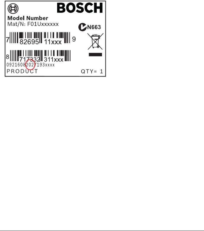
Determine Bosch Security Systems, Inc. Product Manufacturing Date
Use the serial number located on the product label and refer to the Bosch Security Systems, Inc. web site at http://www.boschsecurity.com/datecodes.
The following image shows an example of a product label and highlights where to find the manufacturing date within the serial number.
Bosch Security Systems, Inc. | 2/13 | F01U265457-03 |
8 |

D9412GV4/D7412GV4 v2.00 | Installation and System Reference Guide | 2.0 Lightning Strikes
2.0 Lightning Strikes
The control panels are designed to significantly reduce electromagnetic interference and malfunction generally caused by lightning.
2.1Effects
Any electronic system can be struck directly by lightning or be adversely affected by a lightning strike near the system. When lightning strikes, several things happen:
An electromagnetic wave spreads from the point of the strike inducing high voltages in nearby conductors.
The voltage changes substantially on electrical grounds near the lightning strike.
High voltages are induced in anything directly struck by lightning.
The effects of a lightning strike can include Missing Trouble, Missing Alarm, or Point Bus Trouble events. Occasionally, Reboot and Watchdog events might be sent because the control panel tried to reset itself.
Electronic systems, including control panels, cannot be completely immune to direct or indirect lightning strikes; however, some proven installation practices might greatly reduce the risk of undesirable affects.
2.2Precautions during Installation
To minimize the risk of undesirable effects from lightning strikes on high risk installations that use a point-bus technology:
Do not run wiring outside the building.
If you must install the unit in a metal building, keep the wiring at least 0.61 m (2 ft) away from external metal surfaces.
Earth ground the unit correctly. Do not use an electrical ground or telephone ground.
Avoid running wires near telephone, data, or power lines inside a building. Historical evidence shows that locating control panel wiring at least 0.61 m (2 ft) away from telephone, data, or power lines is successful at minimizing lightning damage. When your data lines must cross the path of AC or other wiring, cross the lines perpendicularly.
Bosch Security Systems, Inc. | 2/13 | F01U265457-03 |
9 |

D9412GV4/D7412GV4 v2.00 | Installation and System Reference Guide | 3.0 Overview
3.0Overview
3.1Configuration and Parts
Figure 1: System Configuration
Bosch Security Systems, Inc. | 2/13 | F01U265457-03 |
10 |
D9412GV4/D7412GV4 v2.00 | Installation and System Reference Guide | 3.0 Overview
Table 2: Control Panel Comparrisons |
|
|
|
|
|
|
|
|
Features |
D9412GV4 |
D7412GV4 |
Access Control |
Yes - 8 doors |
Yes - 2 doors |
Arm/Disarm Users |
999 |
399 |
Cards/Tokens |
999 |
399 |
Passcode-Protected Custom Functions |
16 |
4 |
Number of Points |
246 |
75 |
Number of Off-board Relays |
128 |
64 |
Number of Areas |
32 |
8 |
Number of B920 Two-line Alphanumeric |
16 |
16 |
Keypads |
|
|
Number of B930 ATM Style |
16 |
16 |
Alphanumeric Keypads |
|
|
Number of D1255 Keypads |
16 |
16 |
Number of D1260 Keypads |
8 |
8 |
Number of Phone Lines Supported |
2 |
2 |
|
|
|
|
|
|
3.1.1 |
Parts List |
|
D126 or D1218 Battery |
||
The control panels are shipped assembled |
|
D162 Phone Cord (order two cords if |
|||
from the factory with the following parts: |
|
using the D928 Dual Phone Switcher) |
|||
Literature Pack |
D8103, D8108A, or D8109 Enclosure |
||||
Configured packages are also available. Please |
|||||
|
7000/9000 Series Point Chart Label |
||||
consult the Bosch Security Systems, Inc. |
|||||
|
(P/N: 79-06660-000) |
||||
|
Product Catalog. |
||||
Assembly |
|||||
|
Control Panels (D9412GV4/D7412GV4 |
||||
|
PC board |
||||
|
v2.00) Installation and System Reference |
||||
|
Faceplate shield |
|
|||
|
Guide (P/N: F01U265457) |
||||
|
Mounting skirt |
|
|||
|
|
|
|||
One #6 x 3/4-in screw
3.1.2Parts Available by Separate Order
Order the following components separately to complete a basic eight-point installation.
The D1260 and D1260B Keypads must have firmware version 1.04 or higher for use with the D9412GV4/D7412GV4 v2.00 Control Panels.
B520 Auxiliary Power Supply Module
B420, B426 Ethernet Communication Modules
B920, B930 Keypad
D1255B, D1255, D1260, D1260B Keypad, or D720 Keypad
D1255RB Fire Keypad, D1256RB Fire Keypad, or D1257RB Fire Alarm Annunciator
D1640 Transformer
D1640-CA Transformer (for Canada)
Bosch Security Systems, Inc. | 2/13 | F01U265457-03 |
11 |

D9412GV4/D7412GV4 v2.00 | Installation and System Reference Guide | 3.0 Overview
3.2Accessories
Refer to the Bosch Security Systems, Inc. product catalog for additional information.
The compatible accessories listed in the table below are specific to the D9412GV4/D7412GV4 with firmware v2.00 or greater.
|
Table 3: |
Compatible Accessories1 |
|
|
|
|
|
|
|
Model |
|
Title |
UL |
UL |
Intrusion |
cUL |
|
|
|
|
|
864 |
985 |
|
Intrusion |
|
|
B208 |
|
Octo-input Module |
X |
X |
X |
X |
|
|
B308 |
|
Octo-output Module |
X |
X |
X |
X |
|
|
|
|
|
|
|
|
|
|
|
B420 |
|
Ethernet Communication Module |
X |
X |
X |
X |
|
|
|
|
|
|
|
|
|
|
|
B426 |
|
Ethernet Communication Module |
X |
X |
X |
X |
|
|
B520 |
|
Auxiliary Power Supply Module |
X |
X |
X |
X |
|
|
|
|
|
|
|
|
|
|
|
B810 |
|
RADION receiver SD |
|
X |
X |
|
|
|
|
|
|
|
|
|
|
|
|
B820 |
|
SDI2 Inovonics Interface Module |
|
X |
X |
|
|
|
B920 |
|
Two-line Alphanumeric Keypad |
|
X |
X |
X |
|
|
|
|
|
|
|
|
|
|
|
B930 |
|
ATM Style Alphanumeric Keypad |
|
X |
X |
X |
|
|
|
|
|
|
|
|
|
|
|
D113 |
|
Battery Lead Supervision Module |
X |
X |
X |
X |
|
|
|
|
|
|
|
|
|
|
|
D122/D122L |
|
Dual Battery Harness |
X |
X |
X |
|
|
|
|
|
|
|
|
|
|
|
|
D125B |
|
Powered Loop Interface Module |
X |
X |
X |
X |
|
|
|
|
|
|
|
|
|
|
|
D126 |
|
Standby Battery (12V, 7Ah) |
|
|
|
|
|
|
|
|
|
|
|
|
|
|
|
D129 |
|
Dual Class A Initiation Circuit Module |
X |
X |
X |
|
|
|
|
|
|
|
|
|
|
|
|
D130 |
|
Relay Module |
X |
X |
X |
|
|
|
|
|
|
|
|
|
|
|
|
D185 |
|
Reverse Polarity Module |
X |
X |
X |
|
|
|
|
|
|
|
|
|
|
|
|
D161 |
|
Phone Cord |
|
|
|
|
|
|
D162 |
|
Phone Cord |
|
|
|
|
|
|
|
|
|
|
|
|
|
|
|
D192G |
|
Bell Circuit Supervision Module |
X |
X |
X |
|
|
|
|
|
|
|
|
|
|
|
|
D279A |
|
Independent Zone Control (On-Board and OctoPOPIT |
|
|
X |
|
|
|
|
|
Points) |
|
|
|
|
|
|
|
|
|
|
|
|
|
|
|
D720R |
|
LED Keypad (red) |
|
X |
X |
X |
|
|
D720W |
|
LED Keypad (white) |
|
X |
X |
X |
|
|
|
|
|
|
|
|
|
|
|
D928 |
|
Dual Phone Line Switcher |
X |
X |
X |
X |
|
|
|
|
|
|
|
|
|
|
|
D1255RB |
|
Fire Keypad |
X |
X |
X |
X |
|
|
D1256RB |
|
Fire Keypad |
X |
X |
X |
|
|
|
|
|
|
|
|
|
|
|
|
D1257RB |
|
Fire Alarm Annunciator |
X |
X |
X |
X |
|
|
|
|
|
|
|
|
|
|
|
D1218 |
|
12 V, 17.2 Ah Rechargeable Battery |
|
|
|
|
|
|
D1255/D1255B |
Keypads (General Purpose) |
|
X |
X |
X |
|
|
|
|
|
|
|
|
|
|
|
|
D1255W |
|
Text Keypad (white) |
|
X |
X |
X |
|
|
|
|
|
|
|
|
|
|
|
D1260/D1260B2 |
Keypads |
|
X |
X |
X |
|
|
|
D1640 |
|
16.5 VAC 40 VA Transformer |
X |
X |
X |
|
|
|
|
|
|
|
|
|
|
|
|
D1640-CA |
|
16.4 VAC 40 VA Transformer for Canada |
|
|
|
X |
|
|
|
|
|
|
|
|
|
|
|
D8004 |
|
Transformer Enclosure |
X |
X |
X |
|
|
|
D8125 |
|
POPEX Module |
X |
X |
X |
X |
|
|
|
|
|
|
|
|
|
|
|
D8125MUX |
|
Multiplex Bus Interface |
X |
X |
X |
|
|
|
|
|
|
|
|
|
|
|
|
D8128D |
|
OctoPOPIT Module |
X |
X |
X |
X |
|
|
D8129 |
|
OctoRelay Module |
X |
X |
X |
X |
|
|
|
|
|
|
|
|
|
|
|
D8130 |
|
Release Module |
X |
X |
X |
|
|
|
|
|
|
|
|
|
|
|
|
D8132 |
|
Battery Charger Module |
|
X |
X |
X |
|
|
D9127U/T |
|
POPIT Module |
X |
X |
X |
X |
|
|
|
|
|
|
|
|
|
|
|
D9210C |
|
Access Control Interface Module |
X |
X |
X |
X |
|
|
|
|
|
|
|
|
|
|
|
DX4010V2 |
|
USB/Serial Interface Module |
|
|
|
|
|
|
|
|
|
|
|
|
|
|
|
|
|
|
|
|
|
|
|
|
Bosch Security Systems, Inc. | 2/13 | F01U265457-03 |
|
|
|
12 |
|||
D9412GV4/D7412GV4 v2.00 | Installation and System Reference Guide | 3.0 Overview
DX4020 |
Network Interface Module |
X |
X |
X |
X |
ITS-DX4020-G |
GPRS/GSM Communicator |
X |
X |
X |
|
|
|
|
|
|
|
ICP-SDI-9114 |
SDI Splitter |
X |
X |
X |
|
|
|
|
|
|
|
ITS-EZTS |
Tamper Switch |
|
X |
X |
X |
ISW-D8125CW-V2 |
Commercial Wireless Interface Module |
|
|
|
|
|
|
|
|
|
|
ZX776Z |
PIR Motion Sensor [15 m (50 ft)] with POPIT |
|
|
X |
|
|
|
|
|
|
|
ZX794Z |
PIR Motion Sensor [24 m (80 ft)] with POPIT |
|
|
X |
|
ZX865 |
PIR/Microwave Motion Sensor [+1.7 C (+35 F)] with |
|
|
X |
|
|
POPIT |
|
|
|
|
|
|
|
|
|
|
ZX938Z |
PIR Motion Sensor [18 m (60 ft)] with POPIT |
|
|
X |
|
ZX970 |
PIR/Microwave Motion Sensor [+1.7 C (+35 F)] with |
|
|
X |
|
|
POPIT |
|
|
|
|
|
|
|
|
|
|
RFBT-A |
RADION speciality |
|
|
X |
|
RFDL-11-A |
RADION tritech |
|
|
X |
|
|
|
|
|
|
|
RFDW-SM-A |
RADION contact SM |
|
|
X |
|
|
|
|
|
|
|
RFDW-RM-A |
RADION contact RM |
|
|
X |
|
|
|
|
|
|
|
RFSM-A |
RADION smoke |
|
X |
X |
|
|
|
|
|
|
|
RFRP-A |
RADION repeater |
|
X |
X |
|
|
|
|
|
|
|
RFPR-12-A |
RADION PIR |
|
|
X |
|
|
|
|
|
|
|
RFPR-C12-A |
RADION PIR C |
|
|
X |
|
|
|
|
|
|
|
RFUN-A |
RADION universal transmitter |
|
|
X |
|
|
|
|
|
|
|
1Where the fire alarm transmitter is sharing on premise communications equipment, the shared equipment must be UL Listed (ITE or fire protective signaling).
2Refer to for compatible Inovonics devices.
3Version 1.04 or above.
No wireless detectors have been approved for use with alarm verification points.
For specific installation and operation instructions, please refer to manufacturers’ manuals.
UL requires that the DX4010v2 be used as a temporary programming interface only.
3.3Features in the GV4 Series
Control Panels
3.3.1SDI Interconnect Wiring
Use interconnect wiring to easily connect an SDI bus device to the SDI bus or an SDI2 device to the SDI2 bus without needing to disconnect wires connected to the bus terminals. Possible applications include:
Connecting a DX4010v2 to program the control panel with Remote Programming Software (RPS) at the premises.
Connecting a keypad to test the control panel.
3.3.2Tip and Ring Posts
The tip and ring posts allow connecting a phone or buttset for the purpose of troubleshooting communications between the control panel and the central station. This connection allows monitoring of the dial tone, handshaking tones from the receiver, and communications signals.
3.3.3Telephone Line Sniff
The control panels monitor the phone line for the programmed supervision interval before indicating phone line trouble.
Bosch Security Systems, Inc. | 2/13 | F01U265457-03 |
13 |
D9412GV4/D7412GV4 v2.00 | Installation and System Reference Guide | 3.0 Overview
3.3.4Points
The Bosch Security Systems, Inc. D9412GV4 Control Panel provides up to 246 points of protection. The D7412GV4 Control Panel provides up to 75 points of protection. Point programming parameters determine the control panel’s response to open and shorted conditions on the sensor loop for the point. Several options allow individual point programming to custom-fit the protection to the installation.
Points 1 to 8 are located on the circuit board (on-board points). They are standard sensor loops. The remaining off-board points can be located on point expansion modules on a ZONEX bus, an SDI bus, and/or an SDI2 bus. The ZONEX bus supports any combination of POPIT points using D8128D OctoPOPITs, D8125 POPEX Modules and D9127 POPITs, a ISW-D8125CW-V2 Zonex Inovonics Interface Module, or D8125MUX Modules. The SDI2 bus supports any combination of B208 Octo-input modules, B810 wireless receiver, or a B820 Inovonics Interface Module.
Any points programmed as fire supervisory points are latching.
3.3.5Areas and Accounts
The D9412GV4 supports up to 32 areas. The D7412GV4 supports up to 8 areas. You can assign all points to a single area or distribute them over all supported areas.
The control panel is armed and disarmed by area, and several areas can be armed and disarmed with one menu function. A passcode can also be assigned an authority level that allows a user to arm an area from a remote keypad in another area. Assigning each area its own account number creates up to 32 separate accounts in the D9412GV4 and up to 8 separate accounts in the D7412GV4. Assigning the same account number to different areas, groups them together in a single account.
Area options include exit tone and delay, separate fire and burglary outputs, and multiple opening and closing windows. Area type can be used to create area interdependencies for arming purposes.
3.3.6Digital Communicator
The control panel uses a built-in digital communicator to send reports to the receiver. The control panel sends reports in either the Modem4 or ANSI-SIA Contact ID format.
The control panel connects to an RJ31X or RJ38X jack for telephone line seizure. Connecting to the RJ31X complies with FCC regulations for using the public telephone network. The control panel can be programmed to direct reports to four separate telephone numbers. Adding the D928 Dual Phone Line Switcher Module to the D9412GV4 or the D7412GV4 allows connection and supervision of a second telephone line.
The system can route groups of Event Reports to four different destinations through the phone or over a network. Each report group can be programmed to send reports to one or more destinations. Primary and backup reporting paths can be programmed for each destination and each report group. A custom option allows specification of individual Event Reports to be sent.
3.3.7Keypads
Up to 32 unsupervised keypads can be connected to the system. The available power, number of supervised keypads, and number of areas covered affect the total number of keypads that can be connected.
The system can supervise up to sixteen D1255 keypads, and up to eight D1260 keypads. If the control panel loses communication with the keypad, it sends SDI FAILURE in the Modem4 format or Expansion Module Failure (333) in Contact ID format. The system can support more SDI keypads (up to 32 unsupervised).
In addition to the SDI keypads, the system can support up to 16 B920 and B930 keypads on the SDI2 bus. The control panel supervises all keypads on the SDI2 bus. Any failure to receive an expected response from an SDI2 keypad results in a system fault display on all keypads and an SDI Fault event is sent to the central station if programmed to do so.
Table 4 on page 15 shows the keypads that are compatible with D9412GV4/D7412GV4 v2.00 Control Panels. Refer to 18.0 Keypad Installer Menu for complete details on programming keypad options.
Bosch Security Systems, Inc. | 2/13 | F01U265457-03 |
14 |

D9412GV4/D7412GV4 v2.00 | Installation and System Reference Guide | 3.0 Overview
UL requires all Fire System keypads to be supervised.
Table 4: |
Compatible Keypads |
|
|
|
|
|
|
|
Model |
Display |
Application |
|
|
|
B930 |
5-line LCD display |
Burglary/Access |
|
|
|
B920 |
2-line LCD display |
Burglary/Access |
|
|
|
D1255RB |
16-character |
Fire |
|
alphanumeric |
|
|
|
|
D1256RB |
16-character |
Fire |
|
alphanumeric |
|
|
|
|
D1257RB |
16-character |
Fire |
|
alphanumeric |
|
|
|
|
D1255/ |
16-character |
Burglary |
D1255B/ |
alphanumeric |
|
|
|
|
D1260/ |
4-line by 20- |
Burglary |
D1260B |
character |
|
D1265* |
LCD Touch screen |
Burglary |
|
|
|
*D1265 keypad has not been investigated by UL.
3.3.8Keyswitch
Maintained or momentary closure devices such as keyswitches allow any of the available areas to be armed or disarmed. Point programming determines the loop response and which area a keyswitch controls.
3.3.9Access Control
The D9412GV4 can control eight access doors (each requiring the optional D9210C Access Control Interface Module) with up to 999 uniquely identified cards or tokens. The D7412GV4 can control two access doors with up to 399 uniquely identified cards or tokens. Any of the following can grant access:
Wiegand-style access control device (card reader) connected to the D9210C Access Control Interface Module
Request to enter (RTE) or request to exit (REX) input
Unlock command on a B920/B930
The access control features of the D9412GV4 and D7412GV4 can deny access during armed periods. The control panel can also grant access only to certain authorized users depending on whether the area is all on, part on, or off. Programming for automatic disarming when designated authorized users are granted access is also possible.
The Dual Authentication feature can optionally require passcode entry with presentation of door credentials before access authorization is granted.
3.3.10 Event Memory
The control panel retains point alarm and trouble events in memory for each area. A B930, B920, D1255 (any model), as well as a D1260 (any model) can be used to view event memory by using the Events menu. The control panel clears the previous events for an area from the event memory when the area is turned off.
3.3.11 Event Log
The system stores 1023 events from all areas in its event log. For example, the system adds at least two items to the log each time an area is turned on (arm) or off (disarm), the open (or close) event also contains the previous arming state.
All events can be stored even if the control panel does not send a report for them. The log can be viewed at a keypad, or uploaded using Remote Programming Software (RPS).
3.3.12 Ground Fault Detection
The Earth Ground Terminal on the control panels is electrically isolated from all other terminals to allow the control panels to detect ground fault conditions. A Ground Fault Detect Enable switch (S4) is located just under Terminal 10, Earth Ground, on the control panel. Refer to Section 4.5.2 Ground Fault Detect Enable on page 18 for information on operating this function.
3.3.13 Ground Fault Detection Added Feature
When Ground Fault Detect is enabled (S4 closed), Points can be used for non-powered fire-initiating devices such as heat detectors, four-wire smoke detectors, and pull stations. A D125B Powered Loop Interface or a D129 Dual Class A Interface Module is not required when connecting the non-powered fire-initiating devices to Points.
Bosch Security Systems, Inc. | 2/13 | F01U265457-03 |
15 |

D9412GV4/D7412GV4 v2.00 | Installation and System Reference Guide | 3.0 Overview
3.3.14 Conettix Functions
The D6600/D6100i/D6100IPV6 Conettix System supports data network communications. Conettix allows the D6600/D6100i/D6100IPV6 Receiver/Gateway devices to connect to various network technologies including Ethernet, UDP/IP, and GPRS (General Packet Radio System).
Connecting to a data network is possible using the COM4 or COM1 connection from the D6600/D6100i Receiver to the D6680 Network Adapter. Control panels can send reports through telephone lines, Ethernet, UDP/IP, or GPRS networks to the D6600/D6100i/D6100IPV6 receiver to the central station. Once events are received, they can then be issued to automation software or a network printer through a local area network (LAN) or wide area network (WAN).
Sending events to the central station over a LAN or WAN requires a network interface module (NIM), such as the B426, B420, or DX4020. Sending events over GPRS requires a special NIM, the ITS-DX4020-G.
3.3.15 Programming
Use the RPS, or the Keypad Installer menu, to program the control panels. Refer to the
Control Panels (D9412GV4/D7412GV4 v2.00) Program Entry Guide (P/N: F01U265459)for programming options.
3.3.16 Dual Authentication
The D9412GV4 and D7412GV4 control panels can be configured to require two forms of identification before processing certain system commands. This feature requires a door controller and a keypad to be installed within proximity to each other for user convenience.
Dual Authentication requires a D9210C door controller module even though the configured operation may not be access.
A standard system user has authority to use Dual Authentication if they have a passcode, a door credential (token or card), and appropriate command authority permissions assigned in the door and keypads assigned area. When enabled at a keypad, only the following Passcode Functions require access credentials with passcode entry, Arm / Disarm, Cycle Door (Grant Access), Cycle Relay, and Auto Re-arm. Refer to the Control Panels (D9412GV4/D7412GV4 v2.00) Program Entry
Guide (P/N: F01U265459)and D9210C Installation and Operation Guide (P/N: F01U215232) for details on installation, configuration and operation of this feature.
3.3.17 Other Features
The D9412GV4/D7412GV4 v2.00 Control Panels have many programmable features. Some of the features are listed below. Complete details on all features are in the
Control Panels (D9412GV4/D7412GV4 v2.00) Program Entry Guide (P/N: F01U265459):
Supervision of AC (primary power), battery (secondary power), Zonex, SDI and SDI2 buses, central processing unit (CPU), and two telephone lines
Automatic System Test Reports
Remote access for programming, diagnostics, and log uploads using the remote programming software (RPS)
Fire alarm verification
Programmable alarm outputs
Programmable relay outputs
Opening and closing windows
Skeds (scheduled events)
Limited local programming
Bosch Security Systems, Inc. | 2/13 | F01U265457-03 |
16 |
D9412GV4/D7412GV4 v2.00 | Installation and System Reference Guide | 4.0 Installation
4.0Installation
4.1Installation Preparation
This section contains a general installation procedure and refers to other sections of the document for detailed instructions.
Review this document and the Control Panels (D9412GV4/D7412GV4 v2.00) Program Entry Guide (P/N: F01U265459)before beginning the installation to determine the hardware and wiring requirements for the features used.
Have the following documentation available when reading through this guide:
Control Panels (D9412GV4/D7412GV4 v2.00) Control Panel Owner’s Manual.
Before installation, become familiar with the operation of RPS or the local Programmers menu.
D8103 Universal Enclosure (tan)
D8109 Fire Enclosure (red)
D8108A Attack Resistant Enclosure (tan)
Refer to chapter 17.0 Approved Applications in this guide to determine if the application requires a specific enclosure.
4.3Mounting Enclosure
1.Run the necessary wiring throughout the premises.
2.Mount the enclosure in the desired location. Use all five enclosure mounting holes. Refer to Figure 2.
3.Pull the wires into the enclosure.
Electromagnetic interference (EMI) can cause problems on long wire runs.
4.2Enclosure Options
Mount the control panel assembly in any of the
Bosch Security Systems, Inc. enclosures listed:
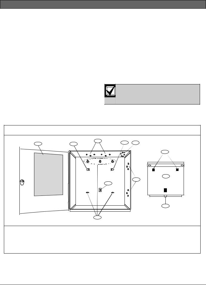
Figure 2: Enclosure Mounting
1 |
2 |
3 |
2 |
4 |
|
||||
|
|
|
||
|
|
|
|
7 |
|
|
|
|
8 |
|
|
|
|
3 |
|
|
|
5 |
|
|
|
|
|
9 |
|
|
6 |
|
|
1 - |
Point chart label |
6 - Enclosure mounting holes (5) |
|
2 - Mounting skirt hooks (2) |
7 - Mounting skirt hook holes (2) |
||
3 - Module mounting holes (12) |
8 - |
Back of D9412GV4/D7412GV4 Control Panel |
|
4 - Tamper switch mounting holes (5) |
9 - |
Lock down tab |
|
5 - |
Skirt mounting hole (1) |
|
|
Bosch Security Systems, Inc. | 2/13 | F01U265457-03 |
17 |

D9412GV4/D7412GV4 v2.00 | Installation and System Reference Guide | 4.0 Installation
4.4Installing the Control Panel
1.Place the control panel over the inside back of the enclosure, aligning the large rectangular openings of the mounting skirt with the mounting hooks of the enclosure. Slide the control panel down so that it hangs on the hooks. Refer to Figure 2, Item 2 on page 17.
2.Remove the tape from the #6 x 1/4-in screw in the mounting tab on the control panel. The screw passes through the mounting tab and into the skirt mounting hole in the enclosure. Tighten the screw to secure the control panel in the enclosure.
3.Connect earth ground to the control panel before making any other connections. Refer to Section 4.5 Connecting Earth Ground.
4.5Connecting Earth Ground
4.5.1Terminal 10
10 
To help prevent damage from electrostatic charges or other transient electrical surges, connect the system to earth ground at Terminal 10 before making other connections. Recommended earth ground references are a grounding rod or a cold water pipe.
Caution: Do not use telephone or electrical ground for the earth ground connection. Use 14 AWG (1.8 mm) to 16 AWG (1.5 mm) wire when making the connection.
Do not connect other control panel terminals to earth ground.
4.5.2Ground Fault Detect Enable
To meet UL 864 requirements, enable Ground Fault Detect.
A ground fault is a circuit impedance to earth ground. The control panel has a ground fault detection circuit that, when enabled, detects ground faults on Terminals 1 to 9 and 11 to 32. The control panel also detects and annunciates ground faults on any device connected to it.
If a ground fault condition occurs, the keypads display SERVC GND FAULT and the control panel transmits a GROUND FAULT TROUBLE, AREA 1.
When the control panel recognizes that the ground fault condition is corrected, and remains corrected for between 5 to 45 consecutive sec, a Restoral Report is sent.
The D9412GV4 and D7412GV4 control panels log and print a Ground Fault event as GROUND FAULT. If communicating in Modem4 format. If communicating in Contact ID format, the control panels generate a Ground Fault (310) event.
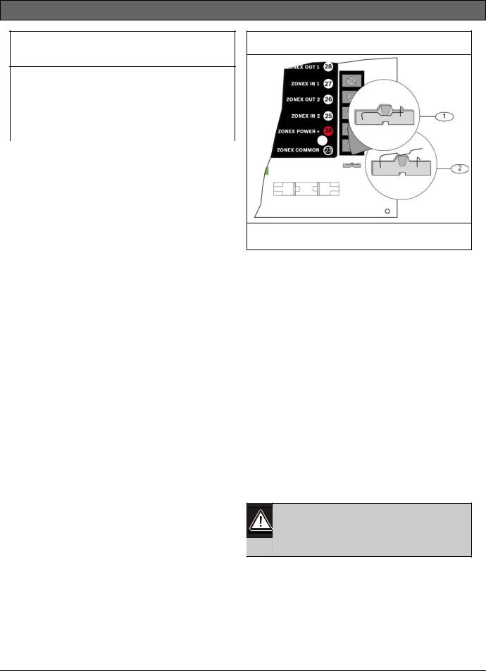
4.5.3Enabling Ground Fault Detection
To enable Ground Fault Detect Enable, lock (close) the S4 Ground Fault Detect Pin on the control panel (Figure 3).
Figure 3: Enabling Ground Fault Detection
1 - S4 Locked (Closed). Control panel detects ground faults.
2 - S4 Unlocked (Open). Control panel does not detect ground faults.
4.5.4Ground Fault Specifications
Table 5 provides the impedance specifications for detecting ground faults when any terminal or field wiring is shorted to ground.
Bosch Security Systems, Inc. | 2/13 | F01U265457-03 |
18 |
D9412GV4/D7412GV4 v2.00 | Installation and System Reference Guide | 4.0 Installation
Table 5: Ground Fault Impedance
Specifications
|
|
Impedance |
Control Panel Detects Ground Fault |
≤ 300 Ω |
Yes |
300 Ω to |
Detection depends upon the |
200 k Ω |
terminal |
≥ 200 k Ω |
No |
4.5.5Locking the Reset Pin
Locking the reset pin disables the control panel (Figure 4). When the control panel is disabled, the system ignores most keypad commands and points. Call for Service appears in some keypad displays when the pin is locked down. SDI2 keypads display “Installation Passcode” when the pin is locked down.
On-board outputs (Terminals 6 and 7) and offboard outputs deactivate when the control panel is reset. Terminal 8 has power when the output is deactivated. Activation interrupts power at that terminal. The on-board output (Terminal 8) remains deactivated when the reset pin is locked in the disable position.
Releasing the reset pin from the closed position resets the control panel. The control panel resets all its timers, counters, indexes, and buffers. Any points that restore after a reset do not generate Restoral Reports.
If the reset pin is placed in the Lock position and all areas are armed, the control panel will not answer RPS over a phone line unless Answer Armed program item has a value other than zero in it. No entry is required for network or RPS Enhanced direct connect communication. Refer to RPS Parameters in RPS Help.
Figure 4: Reset Pin
1 - Reset pin locked (closed)
2 - Reset pin normal (open)
4.6Completing the Installation
If not already complete, make the earth ground connection to Terminal 10 and lock the reset pin in the closed position.
4.6.1Charging the Battery
Connect the battery, then the transformer to allow the control panel to charge the battery while you complete the installation. Refer to
Section 5.0 Power Supply on page 24 for instructions.
On-board Buzzer Sounds at Power Up and Reset: The system performs a series of self-diagnostic tests of hardware, software, and programming at power up and at reset. The buzzer on the control panel sounds during the tests. The selfdiagnostics tests complete in approximately 1 to 3 sec.
If the control panel fails any test, the buzzer continues sounding and a System Trouble message appears at the keypads.
Avoid electrostatic discharge. Always touch Terminal 10, the earth ground connection, before beginning work on the control panel.
If the control panel receives an electrostatic discharge, it might generate Watchdog Reset and Param Fail events.
4.6.2Installing and Wiring Detection Devices
Install and wire detection devices and keypads at their locations throughout the premises. Do not connect the control panel yet.
Bosch Security Systems, Inc. | 2/13 | F01U265457-03 |
19 |
D9412GV4/D7412GV4 v2.00 | Installation and System Reference Guide | 4.0 Installation
Section 8.0 On-Board Points on page 37 contains instructions for wiring the on-board points to detection devices. Section 11.0 Arming Devices on page 60 contains instructions for wiring the keypads.
Instructions for wiring the off-board point POPIT sensor loops are found in the instructions packaged with the POPIT modules.
4.6.3Installing Modules and Outputs
1.Power down the unit by unplugging the transformer and disconnecting the battery.
Always power down the unit when installing modules or outputs, or when making wiring connections to the control panel.
2.Install and wire any modules required for the installation as described in the module’s installation instructions.
Instructions for the D8125 POPEX Module, D8128D OctoPOPIT Module, D8129 OctoRelay Module, D811 Arm Status Relay Module, and D928 Dual Phone Line Switcher appear in this guide.
Refer to Section Off-Board Points on page 41 for D8125 and D8128D instructions. Refer to Off-Board Outputs on page 55 for D8129 and D811 instructions. Refer to Section 7.11 D928 Dual Phone Line Switcher on page 34 for D928 instructions.
Yellow Charging Status LED Remains Lit: If the yellow charging status LED remains lit after five minutes of powering up the control panel, either the battery is deeply discharged or too many powered devices were connected to the control panel. Combined continuous current draw for Terminals 3, 8, 24, and 32, and the accessory connector cannot exceed 1.4 A. Refer to Section 6.0 Power Outputs on page 30 for help.
4.7Updating Control Panel Firmware
When a firmware update is available, installation of the update is performed using either a ROM Update Key or using RPS. Refer to the GV4 Series Control Panel ROM Update Key Instructions on the underside of the control panel faceplate, or refer to RPS Online Help.
4.8Programming the Control Panel
If the control panel is not already programmed, review the Control Panels (D9412GV4/D7412GV4 v2.00) Program Entry Guide (P/N: F01U265459). Ensure that all accessory modules for desired features are available for installation.
Use RPS to load a custom program into the control panel as needed.
4.9Installing the Point Chart Label
The point chart label is required for fire systems with verifications points.
3.If using the power outputs at Terminals 7 or 8, refer to Section Programmable Power Output Terminals 6, 7, and 8 on page 30 for instructions.
4.6.4Connecting the On-board Points and Keypads
Connect the on-board points and keypad wiring to the system. Refer to Section 8.0 On-Board Points on page 37 and Section 11.0 Arming Devices on page 60 for instructions.
4.6.5Powering Up
Reconnect the battery, then plug in the transformer. The buzzer sounds for two sec when the control panel is powered up. Leave the reset pin in the locked position.
A point chart label is included in the literature pack. Install the point chart label for fire or combined fire-and-burglary systems that use verification points.
Use the Control Panels (D9412GV4/D7412GV4 v2.00) Program Record Sheet (P/N: F01U265460) to gather the necessary information for completing the point chart. Fill out the label and install it on the inside of the enclosure door (refer to Figure 2 on page 17).
Avoid smearing the entries on the chart. Use the peel-off backing to press the label in place.
4.10 Testing the System
After installing and programming the control panel, test the system completely. Test the control panel and all devices for proper operation.
Bosch Security Systems, Inc. | 2/13 | F01U265457-03 |
20 |
D9412GV4/D7412GV4 v2.00 | Installation and System Reference Guide | 4.0 Installation
Test after initially programming the control panel.
To meet UL 864 requirements, perform a full system test after any subsequent programming session.
Refer to Section 4.11 Service Walk Test on page 21 for complete Service Walk Test instructions.
Clear after Test: To clear the event memory and report buffer, momentarily close the reset pin. Events stored in the control panel’s event log are not cleared.
4.11 Service Walk Test
The Service Walk Test differs from the standard Walk Test. In the standard Walk Test, point expansion modules whose switches are set for a point number not programmed in the control panel do not appear in the test. In the Service Walk Test, POPITs whose switches are set for a point number that is not programmed in the control panel do appear in the test.
The Service Walk Test allows a user to walk test all 246 points from a control-panel-wide keypad, regardless of the point index type.
Service Walk Test Procedure (B920/B930)
Refer to Walk Test procedures for Service Walk Test options in compatible keypad documentation when using a B920 or B930 Keypad.
1.Choose a keypad to conduct the test. Ensure that the display shows the idle disarmed text.
2.Press the [MENU] key and then go to the [3] Actions > [3] Test > [1]Walk Test > [3] Service menu option.
3.Enter your passcode and press [ENTER]. The keypad shows the number of points that remain to be tested.
4.To view the points, press [ENTER] on a B920 keypad or press the View untested points softkey on a B930 keypad. To scroll through the list of points, use the [PREV] or [NEXT] key.
5.When you fault a point (move in front of a motion sensor for example), the keypad emits a brief tone and shows the point name and information (for example, Area-1 Point-7 Onboard: Short).
A Service Walk Test can also be initiated by account-wide or area-wide keypads but test only those points that are within the scope of the keypad that initiated the function. The Service Walk Test does not test points in armed areas.
Only Walk Test Start and Walk Test End are reported to the central station.
During a Service Walk Test, the summary alarm and summary fire remain off, because there are no Fire or Burg alarm conditions to summarize. The P# Output Response Type feature operates as programmed.
The D7412GV4 does not include the Service Walk Test in the Service Menu. To enable the Service Walk Test function for any GV4 Series Control Panel, add its function code to the Function List of a keypad.
Extra Points display default text: If the switches on a POPIT are set incorrectly to a point number that is not in the program for the control panel, the default text for that point number (PT ###)
appears when the point is faulted.
Faulting the point a second time produces the tone and shows the point text, but does not decrease the count in the ## PTS TO TEST message.
To see the points that remain untested during the Service Walk Test:
a.Press [ESC] when point text appears. The display shows ## PTS TO TEST.
b.Press the [ESC] key. VIEW UNTESTED ? appears.
c.Press [ENT]. ## PTS UNTESTED appears.
d.Press [NEXT] to see a list of the points that have not yet been tested. Move through this list by pressing the [NEXT] key.
e.To resume the Service Walk Test, press [ESC]. ## PTS UNTESTED appears.
f.Press [ESC]. ## PTS TO TEST appears.
g.Resume testing points. To end the Service Walk Test, press [ESC] twice.
Bosch Security Systems, Inc. | 2/13 | F01U265457-03 |
21 |

D9412GV4/D7412GV4 v2.00 | Installation and System Reference Guide | 4.0 Installation
|
6. After the last point is tested, 0 PTS TO TEST |
|
|
enroll, remove or replace wireless points. For |
||||||||||||
|
|
|
|
appears. Press [ESC]. The display shows ALL |
|
|
details in navigation and operation of these |
|||||||||
|
|
|
|
PTS TESTED briefly before returning to idle |
|
|
functions refer to the Control Panels |
|||||||||
|
|
|
|
text. |
|
|
(D9412GV4/D7412GV4 v2.00) Program Entry |
|||||||||
|
|
|
|
|
|
|
|
|
Guide (P/N: F01U265459). |
|||||||
|
|
|
|
|
|
The Service Walk Test, when |
|
|
||||||||
|
|
|
|
|
|
|
|
|||||||||
|
|
|
|
|
|
|
|
|
|
|
|
|
|
|
|
|
|
|
|
|
|
|
performed on a D7412GV4, cannot |
|
|
|
|
|
|
The RF Points menu does not affect |
|
|
|
|
|
|
|
|
|
|
|
|
|
|
|
|
|
|||
|
|
|
|
|
|
|
|
|
|
|
|
|
|
|||
|
|
|
|
|
|
show “0 PTS TO TEST” because the |
|
|
|
|
|
|
the RFIDs learned by the D8125INV |
|
|
|
|
|
|
|
|
|
D7412GV4 is physically unable to |
|
|
|
|
|
|
Wireless Interface Module nor the |
|
|
|
|
|
|
|
|
|
|
|
|
|
|
|
|
|
|||
|
|
|
|
|
|
connect to the second POPEX Module |
|
|
|
|
|
|
ISW-D8125CW-V2 Commercial |
|
|
|
|
|
|
|
|
|
(used for Points 129-247). |
|
|
|
|
|
|
Wireless Interface Module if installed |
|
|
|
|
|
|
|
|
|
|
|
|
|
|
|
|
on the Zonex bus. |
|
|
|
|
|
|
|
|
|
|
|
|
|
|
|
|
||||
|
|
|
|
|
|
|
|
4.11.4 |
RF Diagnostics |
|
||||||
|
|
|
|
|
|
Automatic time-out returns the system |
||||||||||
|
|
|
|
|
|
|||||||||||
|
|
|
|
|
|
|||||||||||
|
|
|
|
|
|
|
|
|
|
|
|
|
|
|
|
|
|
|
|
|
|
|
to idle text: If there is no point or |
|
|
With a B810 wireless receiver, or B820 SDI2 |
|||||||
|
|
|
|
|
|
keypad activity for 20 min., the |
|
|
Inovonics Interface Module installed, the control |
|||||||
|
|
|
|
|
|
|||||||||||
|
|
|
|
|
|
Service Walk Test ends automatically. |
|
|
panel can show detailed wireless communication |
|||||||
|
|
|
|
|
|
The keypad returns to idle text. |
|
|
information for RF points, keyfobs and repeaters. |
|||||||
4.11.1 |
Program the Control panel |
|
|
The RF Diagnostics menu can show real-time |
||||||||||||
|
|
signal strength information for enrolled RF |
||||||||||||||
|
|
|
|
|
|
|
|
|
||||||||
|
Use RPS or the keypads to program the control |
|
|
devices. By monitoring the signal strength of an |
||||||||||||
|
panel. Refer to: |
|
|
individual RF device, the optimal position for |
||||||||||||
|
|
|
|
|
Control Panels (D9412GV4/D7412GV4 |
|
|
installation can be found. |
||||||||
|
|
|
|
|
|
RF device diagnostic information also includes AC |
||||||||||
|
|
|
|
|
|
v2.00)) Program Entry Guide (P/N: |
|
|
||||||||
|
|
|
|
|
|
F01U265459). |
|
|
status, battery status, supervision status, and |
|||||||
|
|
|
|
|
Keypad Installer menu |
|
|
tamper status for all supporting devices. For |
||||||||
|
|
|
|
|
RPS Help |
|
|
details in navigation and operation of these |
||||||||
4.11.2 |
Service Bypass |
|
|
functions refer to the Control Panels |
||||||||||||
|
|
(D9412GV4/D7412GV4 v2.00) Program Entry |
||||||||||||||
|
|
|
|
|
|
|
|
|
||||||||
|
To facilitate system maintenance for service |
|
|
Guide (P/N: F01U265459). |
||||||||||||
|
personnel, a special point bypass option is |
4.11.5 |
IP Diagnostics |
|||||||||||||
|
provided through this menu to remove any point |
|||||||||||||||
|
|
|
With at least one B420 Ethernet Communication |
|||||||||||||
|
from service. The status of points in Service |
|
|
|||||||||||||
|
Bypass can be viewed through the Service Bypass |
|
|
Module, or B426 Ethernet Communication |
||||||||||||
|
Menu. For details in navigation and operation of |
|
|
Module installed on the SDI2 bus, the control |
||||||||||||
|
this function refer to the Control Panels |
|
|
panels can use the diagnostic functions of this |
||||||||||||
|
(D9412GV4/D7412GV4 v2.00) Program Entry |
|
|
menu to retrieve the auto-configured settings |
||||||||||||
|
Guide (P/N: F01U265459). |
|
|
from the module and perform a series of network |
||||||||||||
4.11.3 |
RF Points and Repeaters |
|
|
communication tests. This menu does not apply |
||||||||||||
|
|
to the DX4020 modules on the SDI bus. |
||||||||||||||
|
|
|
|
|
|
|
|
|
||||||||
|
With a B810 wireless receiver, the control panels |
|
|
The Settings option retrieves the following from |
||||||||||||
|
can support up to 238 wireless points, 1000 key |
|
|
|||||||||||||
|
|
|
the selected B420 module: Unit Host Name, MAC |
|||||||||||||
|
fobs, and 8 repeaters within the RADION wireless |
|
|
|||||||||||||
|
|
|
ID, and current IPV4 Address. For the B426 |
|||||||||||||
|
portfolio. The RF Points menu provides the tools |
|
|
|||||||||||||
|
|
|
module, the Settings option retrieves: Unit Host |
|||||||||||||
|
necessary to enroll, remove or replace wireless |
|
|
|||||||||||||
|
|
|
Name, MAC ID, and current IPv6 Address. |
|||||||||||||
|
points. For details in navigation and operation of |
|
|
|||||||||||||
|
|
|
The Connection Test option performs the |
|||||||||||||
|
these functions refer to the Control Panels |
|
|
|||||||||||||
|
(D9412GV4/D7412GV4 v2.00) Program Entry |
|
|
following automated tests for the selected |
||||||||||||
|
Guide (P/N: F01U265459). |
|
|
B426/B420 module: |
||||||||||||
|
With a B820 SDI2 Inovonics Interface Module, the |
|
|
Link |
|
[OK] if Ethernet cable is detected |
|
|||||||||
|
|
|
|
|
|
|
|
[Missing] if Ethernet cable is not |
|
|||||||
|
control panels can support up to 350 RF devices |
|
|
|
|
|
|
|
|
|||||||
|
|
|
|
|
|
|
|
detected. |
|
|||||||
|
and up to eight RF Repeater modules. The RF |
|
|
|
|
|
|
|
|
|||||||
|
|
|
Gateway |
[OK] if an ICMP echo request (PING) |
|
|||||||||||
|
Points menu provides the tools necessary to |
|
|
|
||||||||||||
|
|
|
|
|
|
|
|
response is received from the Gateway |
|
|||||||
|
|
|
|
|
|
|
|
|
|
|
|
|
|
|
||
|
|
|
|
|
|
|
|
|
|
|
|
|
|
|
|
|
|
Bosch Security Systems, Inc. | 2/13 | F01U265457-03 |
|
|
|
|
|
|
22 |
||||||||
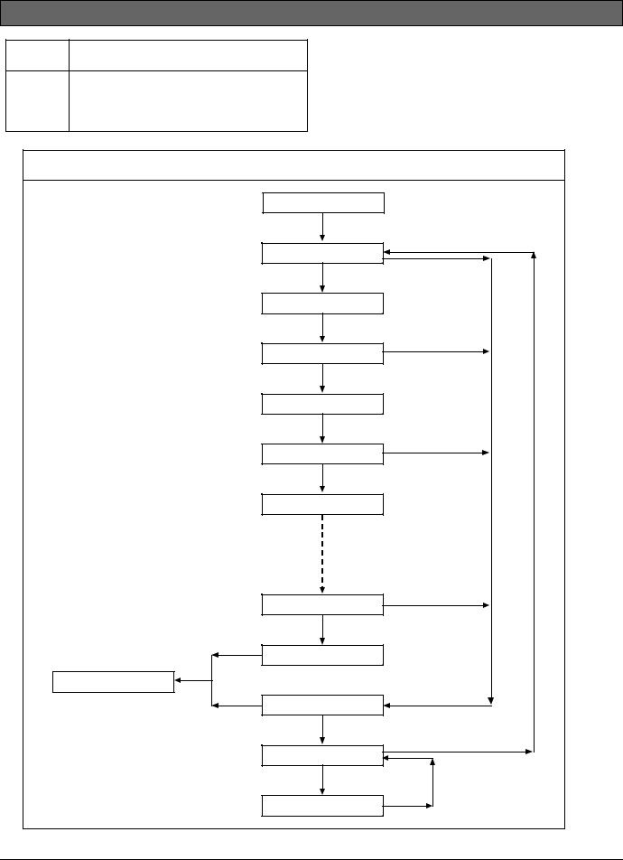
D9412GV4/D7412GV4 v2.00 | Installation and System Reference Guide | 4.0 Installation
Address. [Failure] if response is not received.
Internet [OK] if an ICMP echo request (PING) response is received from the IP Test Address. [Failure] if response is not received.
Refer to the Control Panels (D9412GV4/D7412GV4 v2.00) Program Entry Guide (P/N: F01U265459) for details on the B426/B420 Ethernet Communication Module configuration.
Figure 5: |
Service Walk Test Flow Chart Example |
|
|
|
|
SERVICE WALK? |
|
|
|
[ENT] |
|
|
|
246 PTS TO TEST |
[ESC] |
|
|
Test a device |
|
|
|
|
|
|
|
POINT TEXT |
|
|
|
(Text displays for 60 seconds) |
|
|
|
245 PTS TO TEST |
[ESC] |
|
|
Test a device |
|
|
|
POINT TEXT |
|
|
|
(Text displays for 60 seconds) |
|
|
|
244 PTS TO TEST |
[ESC] |
|
|
|
|
|
|
Test a device |
|
|
|
POINT TEXT |
|
|
|
1 PTS TO TEST |
[ESC] |
|
|
Test a device |
|
|
|
|
|
|
|
0 PTS TO TEST |
|
|
IDLE TEXT |
[ESC] |
|
|
|
VIEW UNTESTED? |
|
|
|
[ENT] |
|
|
|
# PTS UNTESTED |
[ESC] |
|
|
[NEXT] |
[ESC] |
|
|
POINT TEXT |
|
Bosch Security Systems, Inc. | 2/13 | F01U265457-03 |
23 |
||
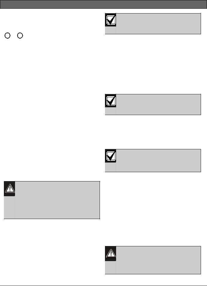
D9412GV4/D7412GV4 v2.00 | Installation and System Reference Guide | 5.0 Power Supply
5.0Power Supply
5.1Primary Power Terminals 1 and 2
1 , 2
5.1.1Primary (AC) Power Circuit
The primary source is a 16.5 VAC, 40 VA, internally-fused transformer (Bosch Security Systems, Inc. Model D1640). The control panel draws 200 mA when idle and 300 mA when in an alarm state. The total available auxiliary current is 1.4 A.
Transient suppressors and spark gaps protect the circuit from power surges. This protection relies on the ground connection at Terminal 10. Ensure that you connect Terminal 10 to a proper ground. Refer to Section 4.5 Connecting Earth Ground on page 18.
AC Power Fail
The system indicates an AC power failure when Terminals 1 and 2 do not have power. The AC Fail Time parameter sets the number of minutes or secs without AC power before the control panel acknowledges the failure and the number of minutes or secs after the power returns before the control panel acknowledges restored power. Refer to the Control Panels (D9412GV4/D7412GV4 v2.00) Program Entry Guide (P/N: F01U265459)for additional information about AC Fail Time and UL 864 requirements.
5.1.2Installing the Transformer
Do not short-circuit the terminals of the transformer: Shorting the terminals opens the internal fuse, causing permanent failure. Connect the transformer to Terminals 1 and 2 of the control panel before plugging it into the power source.
1.Use 18 AWG (1.22 mm) wire (minimum) to connect the transformer to the control panel.
The wire length should be as short as possible. The maximum length is 50 ft (15 m). Connect the battery and plug in the transformer.
2.Route telephone and sensor loop wiring away from any AC conductors, including the transformer wire.
AC wiring can induce noise and low level voltage into adjacent wiring. Route data wiring away from AC and telephone wiring.
Always connect the battery first and then plug in the transformer.
3.Connect the battery. Refer to Section 5.2.2 Installing the Battery on page 25.
4.Plug the transformer into an unswitched, 120 VAC, 60 Hz power outlet only.
5.Secure the transformer to the outlet with the screw provided.
D8004 Transformer Enclosure Required for Fire Systems
Use the D8004 Transformer Enclosure for the D1640 Transformer in fire and combined fire and burglary applications.
Check with the Authority Having Jurisdiction (AHJ) about mounting transformers on specific circuits.
5.2Secondary Power Terminals
5.2.1Secondary (DC) Power
A 12 V sealed lead-acid rechargeable battery (D126) supplies secondary power for auxiliary and alarm outputs, and powers the system during interruptions in primary (AC) power.
Use Lead Acid Batteries Only: The charging circuit is calibrated for leadacid batteries. Do not use gel-cell or nicad batteries.
Extra Batteries Increase Back-up Time
To increase battery back-up time, connect a second 12 V battery in parallel to the first battery. Use a D122 Dual Battery Harness to ensure proper and safe connection. Refer to the
Standby Battery and Current Rating Chart in 17.0 Approved Applications in this guide for battery standby time calculations.
D1218 Battery
The D1218 is a 12 V, 18 Ah battery for use in applications requiring extended battery standby time. Up to two D1218 batteries can be connected when used with a D122 Dual Battery Harness.
Caution: When connecting two D1218 Batteries to the control panel, both must have the same capacity (use two 17.2 Ah batteries or two 18 Ah batteries).
Bosch Security Systems, Inc. | 2/13 | F01U265457-03 |
24 |
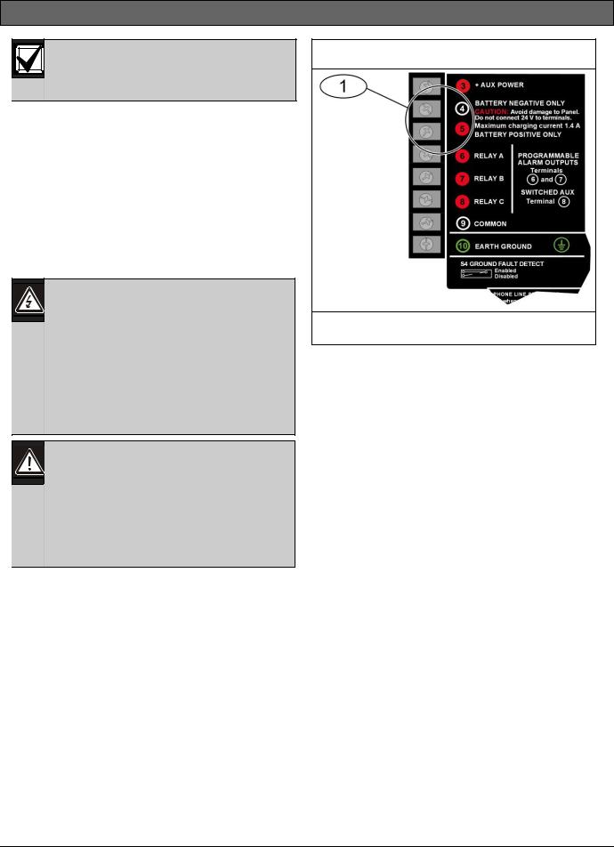
D9412GV4/D7412GV4 v2.00 | Installation and System Reference Guide | 5.0 Power Supply
When using two D1218 batteries, use a separate enclosure, a D122L Dual Battery Harness, and long leads.
5.2.2Installing the Battery
1.Place the battery upright in the base of the enclosure.
2.Locate the red and black leads supplied with the control panel.
3.Connect the black battery lead to Terminal 4, and then to the negative (-) side of the battery.
4.Connect the red battery lead to Terminal 5, and then to the positive (+) side of the battery.
Warning: High current arcs are possible. The positive (red) battery lead and Terminal 5 can create high current arcs if shorted to other terminals or the enclosure. Use caution when working with the positive lead and Terminal 5. Always disconnect the positive (red) lead from the battery before removing it from Terminal 5.
Caution: The battery terminals and wire are not power limited. A 0.25 in (6.4 mm) space must be maintained between the battery terminals, battery wiring, and all other wiring. Battery wiring cannot share the same conduit, conduit fittings, or conduit knock-outs with other wiring.
Figure 6: Battery Terminals
1 - Battery terminals. Terminal 5 is non-power limiting.
Bosch Security Systems, Inc. | 2/13 | F01U265457-03 |
25 |
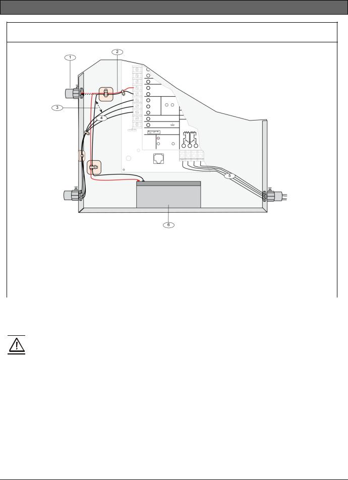
D9412GV4/D7412GV4 v2.00 | Installation and System Reference Guide | 5.0 Power Supply
Figure 7: Non-Power-Limited Wiring
1 - Conduit required for use with external |
4 - Output wires |
|
|
||
|
batteries. |
5 - Input or Point wires |
|
|
|
2 - |
Battery wires |
6 - Standby battery 12 V sealed lead-acid |
|||
3 - 0.25 in (6.4 mm) minimum. To ensure proper |
rechargeable battery D1246/D1218 |
||||
|
spacing, use tie-wraps or similar devices to |
|
|
|
|
|
secure wires. |
|
|
|
|
|
|
|
|
|
|
5.2.3 |
Replacing the Battery |
Refer to the Standby Battery and Current Rating |
|
||
Replace batteries every 3 to 5 years under normal |
Chart in the 17.0 Approved Applications of this |
||||
use. Record the date of installation directly on |
guide for battery standby time calculations. |
||||
the battery. |
D8132 Specifications |
|
|
||
|
|
|
|
|
|
|
Caution: Exceeding the maximum |
|
Operating Voltage |
16.5 VAC supplied from |
|
|
|
|
D1640 transformer |
||
|
output ratings or installing the |
|
|
||
|
|
|
|
|
|
|
transformer in an outlet that is |
|
Operating Current |
1200 mA of rectified AC |
|
|
|
||||
|
routinely switched off causes heavy |
|
|
|
|
|
|
Float Voltage |
13.9 VDC maximum |
||
|
discharges. Routine heavy discharges |
|
|||
|
|
|
|
|
|
|
|
Dimensions (H x W x D) |
0.75 in x 3.0 in x 5.0 in |
||
|
can lead to premature battery failure. |
|
|||
D8132 Boost Battery Backup: Adding a D8132 |
|
|
(1.9 cm x 7.6 cm x 12 cm) |
||
|
|
|
|||
Battery Charger Module supports additional |
|
|
|
||
batteries of up to 27 Ah capacity, if required. |
|
|
|
||
The control panel, plus any connected D8132 Modules and/or a auxiliary power supply, must be on the same AC circuit to discharge evenly if AC power fails. The B520 does not need to be on the same AC circuit as the control panel.
Bosch Security Systems, Inc. | 2/13 | F01U265457-03 |
26 |
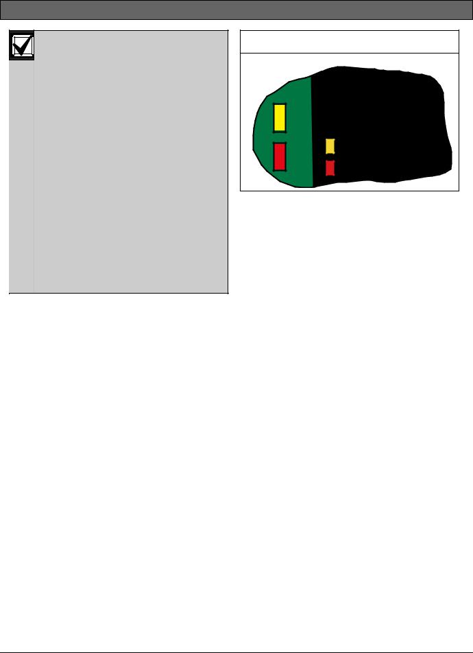
D9412GV4/D7412GV4 v2.00 | Installation and System Reference Guide | 5.0 Power Supply
The control panel and the D8132 (or B520 Auxiliary Power Supply Module) must share COMMON.
Figure 26 on page 61 shows the common form of the D8132 Module connected to the common on the keypad and the common on the control panel. Any stand-alone power supply powering any device connected to the control panel must also be connected to a common terminal on the control panel.
If using the ground fault detection capability on the control panels with an external power supply, ensure that the external selected power supply isolates its earth ground connection from the negative side of the auxiliary power output. External power supplies that do not isolate earth ground can cause ground fault conditions on the control panel.
5.2.4Battery Supervision
When battery voltage drops to 13.8 VDC, the yellow Charging Status LED illuminates. When the battery voltage drops to 12.0 VDC to 11.8 VDC, the red Low Battery LED lights, and the keypad or keypads display SERVC LOW BATT on the keypad display. The control panel (if programmed for power supervision) sends a BATTERY LOW report in the Modem4 communication format. It sends a Low System Battery (302) report in the Contact ID format.
If the battery is missing or shorted, the red Low Battery LED flashes at the same rate as the green Operation Monitor LED. If the control panel is programmed for power supervision, it sends a BATTERY MISSING report in the Modem4 communication format, or Control Panel Battery Missing (311) report in the Contact ID format.
When battery voltage returns to 13.7 VDC, the Low Battery LED turns off and the keypad or keypads clear the SERVC LOW BATT message on the keypad display. If the control panel is programmed for power supervision, it sends a BATTERY RESTORAL report in the Modem4 communication format or a Control Panel Battery Restored to Normal (302) report in the Contact ID format. At 13.9 VDC, the yellow Charging Status LED stops lighting.
Figure 8: Charging and Battery LEDs |
LEDs Off When Normal |
10.2 VDC - Battery Load Shed |
YELLOW - Charging Status |
RED - Low Battery - 12.1 VDC |
Investigate Low Battery reports immediately: If primary (AC) power is off and the discharge continues, the control panel becomes inoperative when the battery voltage drops below 10.2 VDC.
5.2.5Battery Charging Circuit Float Charge
The float voltage for the battery charging circuit is 13.9 VDC at a maximum current of 1.4 A, less any devices connected to the control panel. If the float voltage drops below 13.8 VDC due to overload or battery discharge, the yellow Charging Status LED lights.
Loss of AC Load Shed Output protects battery: During an AC power loss, the battery supplies all power to the security system. If the battery voltage falls below 10.0 V during an AC power loss, a load shed output isolates the battery from the control panel and disables the control panel. Load shed protects the battery from being damaged by deep discharge.
When AC power restores, the load shed output reconnects the charging circuit on the control panel to the battery and the battery begins to recharge.
Overcharge Load Shed With AC Present: If more than 1.4 A of auxiliary current draw from the control panel occurs, the battery supplies the current and begins to discharge. If this situation is not corrected, the battery continues to discharge and at 11.8 VDC to 12.0 VDC, SERV LOW BATT appears on the keypad display.
When the battery voltage drops below 10.0 VDC, the control panel shuts down. Remove all loads to the control panel and disconnect AC power. Fix the condition creating the over current. Add a new battery and reconnect AC power.
Bosch Security Systems, Inc. | 2/13 | F01U265457-03 |
27 |

D9412GV4/D7412GV4 v2.00 | Installation and System Reference Guide | 5.0 Power Supply
A shorted battery condition is created either by a shorted cell inside the battery or by a short on Terminals 4 and 5. A shorted battery might cause the control panel to operate in an unsafe way. This condition generates WATCHDOG RESET reports.
Reset the control panel by momentarily placing the reset pin in the disable position. Refer to Figure 4 on page 19. The red Low Battery LED continues flashing until the control panel resets.
5.2.6Battery Discharge and Recharge Schedule
Table 6: Battery Discharge and Recharge
Schedule
|
|
Discharge Cycle |
|
AC Off: |
AC Fail Report when AC fails, if |
|
control panel is programmed to |
|
report AC failure at occurrence. |
13.9 VDC: |
Charging float level. |
13.8 VDC: |
Charging status LED on. |
12.0 VDC: |
Low Battery and AC Fail Reports if |
|
programmed. Low battery LED on. |
< Ω 10.0 |
Battery load shed (processing |
VDC: |
functions continue if AC is |
|
present). |
|
|
Recharge Cycle |
|
AC On: |
Load shed output reset; battery |
|
charging begins; Battery Trouble |
|
and AC Restoral Reports sent. |
13.7 VDC: |
Battery Restoral Reports sent. Low |
|
battery LED off. |
13.9 VDC: |
Changing status LED off; battery |
|
float charged. |
Bosch Security Systems, Inc. | 2/13 | F01U265457-03 |
28 |

D9412GV4/D7412GV4 v2.00 | Installation and System Reference Guide | 5.0 Power Supply
Table 7: |
Charging Status and Low Battery LEDs |
|||
|
|
|
|
|
|
|
|
|
|
|
|
|
LED |
|
|
|
|
|
|
Type |
|
Color |
State |
Action |
|
|
|
|
|
Charging Status |
Yellow |
|
Shows the charging status of the battery. Refer to Figure 8 |
|
LED |
|
|
|
on page 27 for location. |
|
|
Yellow |
Off |
Battery is fully charged. |
|
|
|
|
If the battery is missing, shorted, or reversed, the Charging |
|
|
|
|
Status LED is off, but the red Low Battery LED is flashing. |
|
|
Yellow |
On |
Battery float charge is below 13.8 VDC. If AC is present, the |
|
|
|
|
battery is charging. |
|
|
|
|
Indicates the combined current draw from all outputs |
|
|
|
|
exceeds 1.4 A. This is normal under alarm conditions for |
|
|
|
|
non-fire systems with sirens or bells drawing more than 1.4 |
|
|
|
|
A. If the LED lights regularly for extended periods or does |
|
|
|
|
not go out, check the current draw for devices connected to |
|
|
|
|
the power outputs. Refer to Section 6.0 Power Outputs on |
|
|
|
|
page 30 for instructions. |
|
|
Yellow |
Flash once per |
System is checking the battery. |
|
|
|
minute |
|
|
|
|
|
|
Low Battery LED |
Red |
|
Shows the condition of the battery. Refer to Figure 8 on |
|
|
|
|
|
page 27 for location. |
|
|
Red |
Off |
Battery is fully charged. |
|
|
|
|
|
|
|
Red |
On |
Battery voltage dropped to between 12.0 VDC and 11.8 VDC. |
|
|
|
|
LED turns off when voltage reaches 13.7 VDC. |
|
|
Red |
Flash |
Battery is missing or shorted. |
|
|
|
|
|
Bosch Security Systems, Inc. | 2/13 | F01U265457-03 |
29 |
D9412GV4/D7412GV4 v2.00 | Installation and System Reference Guide | 6.0 Power Outputs
6.0 Power Outputs
6.1Circuit Protection
Three self-resetting circuit breakers protect the control panel from short circuits on the continuous and programmable power outputs. If the control panel is programmed for power supervision and a short circuit occurs on one of the power outputs, the control panel sends BATTERY LOW and BATTERY MISSING when using Bosch Security Systems, Inc. Modem4 communicator format. Under the same conditions when using Contact ID communicator format, the control panel sends Control Panel Battery Low (302) and Control Panel Battery Missing (311).
One self-resetting circuit breaker protects:
Terminal 3: Auxiliary Power
Terminal 24: Zonex Power
A short circuit on one terminal disrupts power to the other terminal.
Another self-resetting circuit breaker protects:
Terminal 6: Alarm Power Output
Terminal 7: Alternate Alarm Power Output
Terminal 8: Switched Auxiliary Power.
A short circuit on one of the terminals disrupts power to the other two terminals.
The third self-resetting circuit breaker protects Terminal 32: Power +.
UL requires any device powered from a power output to be supervised.
UL requires that power outputs are not shared between fire and non-fire devices unless all devices are in conduit within 20 ft and are in the same room.
6.2Total Available Power
The system produces up to 1.4 A of combined power at 12.0 VDC nominal for special application use. The outputs listed below share the available power. These outputs are shown as red circles on the faceplate.
3 Auxiliary Power: Use this terminal to power devices requiring continuous power.
6(Output A) - Alarm Power Output: Programmable output normally open, power on alarm.
7(Output B) - Alternate Alarm Power Output: Programmable output normally open, power on alarm.
8(Output C) - Switched Auxiliary Power: Programmable output normally closed, switches power off when the Sensor Reset command is executed.
24 Zonex Power: Use this terminal to power Zonex modules such as the D8125, D8128D, and D8129 Modules.
32 SDI Power +: Use this terminal to power serial device interface (SDI) devices such as keypads, or the D9210C Access Control Interface Modules.
36 SDI2 Power +: Use this terminal to power serial device interface (SDI2) devices such as the B208 Octo-input Module, the B308 Octo-output Module, the B426/B420 Ethernet Communication Module, RADION wireless receiver, B920 Two-line Alphanumeric Keypad, B930 ATM Style Alphanumeric Keypad, and the B820 Inovonics Interface Module.
Accessory Connector: The D928 Dual Phone Line Switcher connects to the accessory connector.
6.3Continuous Power Output Terminals 3, 8, 24, and 32
3 , 8 , 24 , 32
The continuous current draw for powered devices connected to Terminals 3, 8, 24, and 32, and the accessory connector must not exceed 1.4 A. Devices powered from these outputs operate at 12.0 VDC Nominal.
Power Restricted for Fire and Combined Fire and Burglary Systems: Use the Fire System Power Formula to calculate the current available for fire and combined fire and burglary systems (refer to
Section 6.4 Programmable Power Output Terminals
6, 7, and 8).
6.4 Programmable Power Output Terminals 6, 7, and 8
6 , 7 , 8
Bosch Security Systems, Inc. | 2/13 | F01U265457-03 |
30 |
 Loading...