


zyxel GS1920, GS2210, GS2220, GS3700, XGS1930 operation manual
...www.zyxel.com
Switch Series
Zyxel GS1920 / GS2210 / GS2220 / GS3700 / XGS1930 / XGS2210 / XGS3700 / XGS4600 / XS1920 / XS1930 / XS3700 / XS3800
Edition 2020.1
Handbook
Default Login Details
LAN Port IP Address |
https://192.168.1.1 |
User Name |
admin |
Password |
1234 |
Copyright © 2020 ZyXEL
1/245

www.zyxel.com |
|
Communications Corporation |
|
Contents |
|
Basic principles for network management ................................................. |
8 |
1.1 How to change the switch management IP address to avoid |
|
accessing the wrong device........................................................................ |
8 |
1.1.1 Configuration in the Switch-2......................................................... |
9 |
1.1.2 Test the Result ................................................................................. |
11 |
1.2 How to configure the switch with a device name to avoid accessing |
|
the wrong device ........................................................................................ |
12 |
1.2.1 Configuration in Switch-1.............................................................. |
13 |
1.2.2 Test the Result ................................................................................. |
14 |
1.3 How to configure the switch to update the time from an NTP server15 |
|
1.3.1 Configuration in Switch................................................................. |
16 |
1.3.2 Test the Result ................................................................................. |
17 |
1.3.3 What could go wrong?................................................................. |
19 |
1.4 How to configure the switch to backup events on a SYSLOG server |
|
....................................................................................................................... |
20 |
1.4.1 Configure the Switch-1 ................................................................. |
21 |
1.4.2 Test the Result ................................................................................. |
23 |
1.4.3 What could go wrong?................................................................. |
24 |
1.5 How to configure the switch with a port name to quickly identify |
|
directly connected devices ....................................................................... |
25 |
1.5.1 Configure Switch-1 ........................................................................ |
26 |
1.5.2 Test the Result ................................................................................. |
27 |
1.6 How to collect the Diagnostic Info....................................................... |
28 |
1.6.1 Collect the Diagnostic Info from web GUI................................. |
29 |
1.6.2 Test the Result ................................................................................. |
30 |
1.7 How to change the default administrator password.......................... |
31 |
1.7.1 Change the default administrator password............................ |
32 |
1.7.2 Test the Result ................................................................................. |
33 |
1.8 How to configure a whitelist for remote management to prevent |
|
unauthorized access................................................................................... |
34 |
1.8.1 Configure the whitelist of the remote management............... |
35 |
1.8.2 Test the Result ................................................................................. |
36 |
|
2/245 |

www.zyxel.com
1.8.3 What could go wrong?................................................................. |
37 |
Designing the Local Area Network ............................................................ |
38 |
2.1 How to configure the switch to separate traffic between |
|
departments using VLAN ............................................................................ |
38 |
2.1.1 Configure Switch-1 ........................................................................ |
39 |
2.1.2 Configure Switch-2 ........................................................................ |
42 |
2.1.3 Test the Result ................................................................................. |
44 |
2.2 How to configure the switch to route traffic across VLANs ................ |
45 |
2.2.1 Configure VLAN 10 ........................................................................ |
46 |
2.2.2 Configure VLAN 20 ........................................................................ |
48 |
2.2.3 Set the gateway on PC-1 and PC-2 ........................................... |
50 |
2.2.4 Test the Result ................................................................................. |
52 |
2.2.5 What could go wrong................................................................... |
53 |
2.3 How to configure the switch to perform DHCP service in a VLAN .... |
54 |
2.3.1 Configure VLAN 10 ........................................................................ |
55 |
2.3.2 Configure VLAN 20 ........................................................................ |
57 |
2.3.3 Configure the Switch and PC ...................................................... |
59 |
2.3.4 Test the Result ................................................................................. |
62 |
2.3.5 What Could Go Wrong ................................................................. |
63 |
2.4 How to Configure the Switch to Translate Customer VLAN to Service |
|
Provider VLAN .............................................................................................. |
64 |
2.4.1 Configuration on the Core Switch .............................................. |
66 |
2.4.2 Configuration on the Edge Switch.............................................. |
68 |
2.4.3 Test the Results................................................................................ |
70 |
Improving Network Reliability .................................................................... |
73 |
3.1 How to configure a stacked switch to ensure high server availability |
|
....................................................................................................................... |
73 |
3.1.1 Configure Switch-1 and Switch-2 for Stacking .......................... |
74 |
3.1.2 Configure Link Aggregation on Stacked switch ....................... |
76 |
3.1.3 Configure Link Aggregation on Switch-3 ................................... |
77 |
3.1.4 Test the Result ................................................................................. |
78 |
3.1.5 What Could Go Wrong ................................................................. |
79 |
3.2 How to configure RSTP in a ring topology ........................................... |
80 |
3.2.1 Configure Switch............................................................................ |
81 |
3.2.2 Test the Result ................................................................................. |
84 |
3.2.3 What Could Go Wrong ................................................................. |
86 |
|
3/245 |

www.zyxel.com
3.3 How to configure VRRP to provide hosts with a redundant gateway |
|
....................................................................................................................... |
87 |
3.3.1 Configuration in the Gateway-A ................................................ |
88 |
3.3.2 Configuration in the Gateway-B ................................................. |
91 |
3.3.3 Test the Result ................................................................................. |
94 |
3.3.4 What Could Go Wrong?............................................................... |
96 |
3.4 How to configure bandwidth control to limit incoming or outgoing |
|
traffic rate ..................................................................................................... |
97 |
3.4.1 Configure Switch............................................................................ |
98 |
3.4.2 Test the Result ................................................................................. |
99 |
3.5 How to configure ACL to rate limit IP traffic ...................................... |
100 |
3.5.1 Configure VLAN and Route Traffic............................................ |
101 |
3.5.2 Configure the Classifier ............................................................... |
102 |
3.5.3 Configure the ACL (Policy Rule) ................................................ |
104 |
3.5.4 Test the Result ............................................................................... |
106 |
3.5.5 What Could Go Wrong ............................................................... |
108 |
3.6 How to Implement VRRP with Multiple Routing Interface Combine |
|
with HA-pro Using Zyxel Enterprise Switch .............................................. |
109 |
3.6.1 Configuration ............................................................................... |
111 |
3.6.2 Verification.................................................................................... |
126 |
3.6.3 What may go wrong? ................................................................. |
127 |
3.7 How to Configure the Switch to Tunnel Layer 2 Protocol Packets |
|
Through Service Provider Network ........................................................... |
128 |
3.7.1 Configuration on the Edge Switch............................................ |
130 |
3.7.2 Configuration on the Customer Switch.................................... |
134 |
3.7.3 Test the Results.............................................................................. |
136 |
3.7.4 What Could Go Wrong ............................................................... |
137 |
Designing an IPTV Network....................................................................... |
138 |
4.1 Introduction for IGMP .......................................................................... |
138 |
4.1.1 What are General Queries and Group Specific Queries? .... |
138 |
4.1.2 What are IGMP Snooping Querier Modes? ............................. |
138 |
4.1.3What are the differences between IGMP Snooping
fast/normal/immediate leave? |
.......................................................... 139 |
4.2 How to configure IGMP routing for multicast clients in a different LAN |
|
..................................................................................................................... |
140 |
4.2.1 Configure Switch-1 ...................................................................... |
141 |
|
4/245 |

www.zyxel.com
4.2.2 Configure Switch-2 ...................................................................... |
142 |
4.2.3 Test the Result ............................................................................... |
143 |
4.2.4 What Could Go Wrong ............................................................... |
144 |
4.3 How to configure IGMP Snooping for multicast clients in the same |
|
LAN .............................................................................................................. |
145 |
4.3.1 Configure Switch.......................................................................... |
146 |
4.3.2 Test the Result ............................................................................... |
147 |
Network Security........................................................................................ |
148 |
5.1 How to configure the port security to limit the number of connected |
|
devices ....................................................................................................... |
148 |
5.1.1 Configure Switch-1 ...................................................................... |
149 |
5.1.2 Test the Result ............................................................................... |
150 |
5.1.3 What Could Go Wrong ............................................................... |
151 |
5.2 How to configure MAC filter to block unwanted traffic ................... |
152 |
5.2.1 Configure Switch-1 ...................................................................... |
153 |
5.2.2 Test the Result ............................................................................... |
154 |
5.2.3 What Could Go Wrong ............................................................... |
155 |
5.3 How to configure the switch to prevent IP scanning........................ |
156 |
5.3.1 Configuration in the Switch ........................................................ |
157 |
5.3.2 Test the Result ............................................................................... |
158 |
5.3.3 What Could Go Wrong?............................................................. |
161 |
5.4 How to Configure the Switch and RADIUS Server to Provide Network |
|
Access through 802.1x Port Authentication ............................................ |
162 |
5.4.1 Configuration in the Switch ........................................................ |
163 |
5.4.2 Configuration in the RADIUS-Server .......................................... |
165 |
5.4.3 Test the Result ............................................................................... |
166 |
5.4.4 What May Go Wrong?................................................................ |
170 |
5.5 How to configure the switch to send unauthorized users in a guest |
|
VLAN ........................................................................................................... |
171 |
5.5.1 Configure 802.1x Port Authentication on the Switch ............. |
172 |
5.5.2 Configure VLAN for Guest VLAN ............................................... |
172 |
5.5.3 Configure Guest VLAN for Failed Authentication................... |
172 |
5.5.4 Configure the RadiusServer........................................................ |
173 |
5.5.5 Configure the setting on User-A, User-B and Guest................ |
174 |
5.5.6 Test the Result ............................................................................... |
176 |
5.5.7 What Could Go Wrong ............................................................... |
178 |
|
5/245 |

www.zyxel.com
5.6 How to Configure the Switch and RADIUS Server to Provide Network
Access through Device MAC Address .................................................... |
180 |
5.6.1 Configuration in the Switch ........................................................ |
181 |
5.6.2 Configuration in the RADIUS-Server .......................................... |
183 |
5.6.3 Test the Result ............................................................................... |
184 |
5.6.4 What Could Go Wrong?............................................................. |
185 |
5.7 How to configure the switch to prevent ARP spoofing..................... |
186 |
5.7.1 Configuration in the Switch ........................................................ |
187 |
5.7.2 Test the Result ............................................................................... |
189 |
5.7.3 What Could Go Wrong?............................................................. |
190 |
5.8 How to Configure the Switch to Protect Against Rogue DHCP Servers |
|
..................................................................................................................... |
191 |
5.8.1 Configuration in the Switch ........................................................ |
192 |
5.8.2 Test the Result ............................................................................... |
195 |
5.8.3 What Could Go Wrong?............................................................. |
196 |
5.9 How to configure IPSG static binding for trusted network devices.197 |
|
5.9.1 Configuration in the Switch ........................................................ |
198 |
5.9.2 Test the Result ............................................................................... |
199 |
5.10 How to configure ACL to block unwanted traffic ........................... |
200 |
5.10.1 Configure VLAN and Route Traffic.......................................... |
201 |
5.10.2 Configure the Classifier ............................................................. |
202 |
5.10.3 Configure the Policy Rule ......................................................... |
204 |
5.10.4 Test the Result ............................................................................. |
205 |
5.10.5 What Could Go Wrong ............................................................. |
206 |
5.11 How to use ACL to mirror traffic of a specific criteria..................... |
207 |
5.11.1 Configuration of ACL ................................................................ |
209 |
5.11.2 Test the Result ............................................................................. |
213 |
5.11.3 What May Go Wrong ................................................................ |
214 |
5.12 How to Separate Traffic through L2 Port Isolation ........................... |
215 |
5.12.1 Configuration in the Switch...................................................... |
218 |
5.12.2 Test the Result ............................................................................. |
220 |
5.12.3 What May Go Wrong ................................................................ |
222 |
Implementing VOIP ................................................................................... |
223 |
6.1 How to configure an IP Phone's VLAN using LLDP-MED ................... |
223 |
6.1.1 Configure VLAN for IP Phone ..................................................... |
224 |
6.1.2 Configure Switch.......................................................................... |
225 |
|
6/245 |

www.zyxel.com
6.1.3 Test the Result ............................................................................... |
227 |
6.1.4 What Could Go Wrong ............................................................... |
228 |
6.2 How to configure the switch to separate VOIP traffic from data traffic |
|
..................................................................................................................... |
229 |
6.2.1 Configure VLAN 100 for IP Phone .............................................. |
230 |
6.2.2 Configure Voice VLAN................................................................ |
231 |
6.2.3 Test the Result ............................................................................... |
232 |
6.2.4 What Could Go Wrong ............................................................... |
233 |
6.3 How to configure the switch to improve Voice traffic quality......... |
234 |
6.3.1 Configure VLAN for voice traffic ............................................... |
235 |
6.3.2 Configure Voice VLAN................................................................ |
236 |
6.3.3 Configure Mirroring (For “Test the Result”) ............................... |
237 |
6.3.4 Test the Result ............................................................................... |
238 |
6.3.5 What Could Go Wrong ............................................................... |
239 |
6.4 How to Configure Voice VLAN on Zyxel Switch................................ |
240 |
6.4.1 Configuration ............................................................................... |
241 |
6.4.2 Test the result ................................................................................ |
244 |
6.4.3 What Could Go Wrong ............................................................... |
245 |
7/245
www.zyxel.com
Basic principles for network management
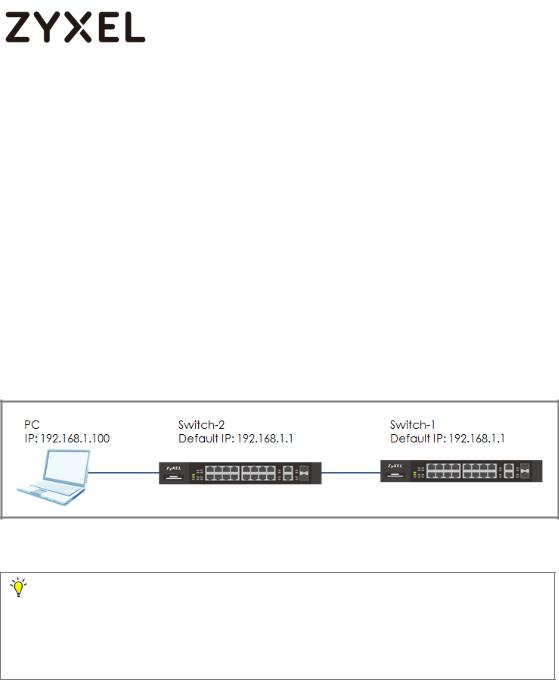
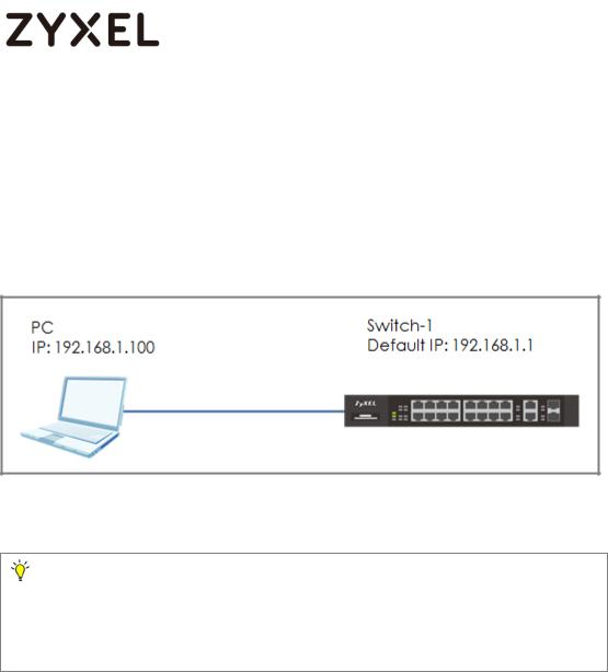
1.1 How to change the switch management IP address to avoid accessing the wrong device
This example shows administrators how to use the Web GUI to manage the IP addresses of the switches and avoid administrators from unintentionally accessing the wrong devices. As shown below, there are two switches in the environment. Both default IP addresses of the two switches are 192.168.1.1.
Figure 1 Two switches are using the same default IP address
Note:
All network IP addresses and subnet masks are used as examples in this article. Please replace them with your actual network IP addresses and subnet masks. This example was tested using XGS4600-32 (Firmware Version: V4.50).
8/245
www.zyxel.com
1.1.1 Configuration in the Switch-2
1Disconnect the link between Switch-1 and Switch-2.
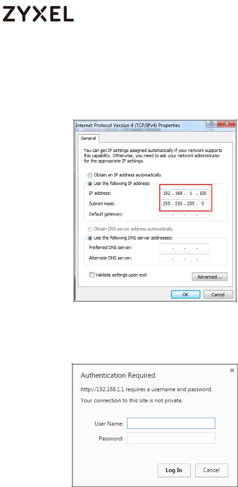
2Set the PC’s IP address on to the same subnet as the switches. For example, set the PC IP address as 192.168.1.100.
3Open a browser (IE, Chrome, Safari, Firefox, etc….). Go to website http://192.168.1.1 (default management IP address).
Key in “username: admin; password: 1234” and log in.
9/245
www.zyxel.com
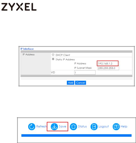
4Enter the webpage and go to Menu > Basic Setting > IP Setup > IP Configuration. Set the IP address you prefer, for example
192.168.1.2. Then click Add.
5Log back in using the new IP address 192.168.1.2. After logging in again, remember to click the Save icon to save the new configurations.
10/245
www.zyxel.com
1.1.2Test the Result
1Log in via the web GUI and go to Menu > Basic Setting > IP Setup > IP Configuration. Check if the IP address is already configured as 192.168.1.2.
11/245
www.zyxel.com
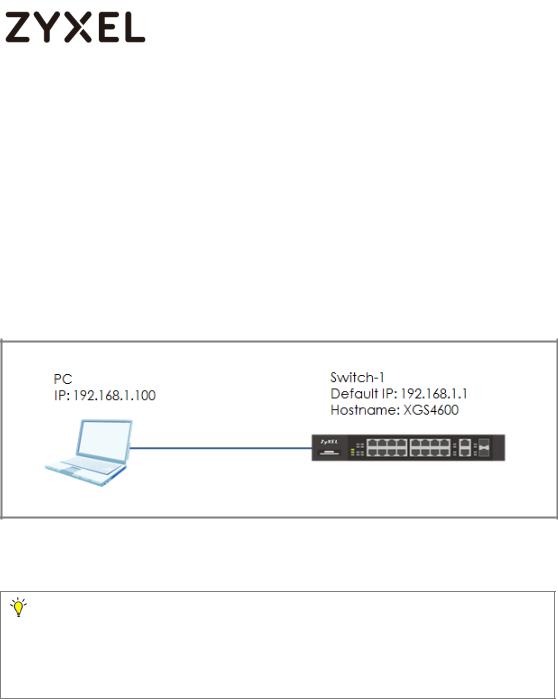
1.2 How to configure the switch with a device name to avoid accessing the wrong device
This example shows administrators how to use the Web GUI to manage device name and avoid accessing the wrong devices. As shown below, the PC connects with Switch-1 in the environment. In the default setting, device name (System Name) will be the model name (XGS4600 in this example).
Figure 2 Change the device name of the switch
Note:
All network IP addresses and subnet masks are used as examples in this article. Please replace them with your actual network IP addresses and subnet masks. This example was tested using XGS4600-32 (Firmware Version: V4.50).
12/245
www.zyxel.com
1.2.1Configuration in Switch-1
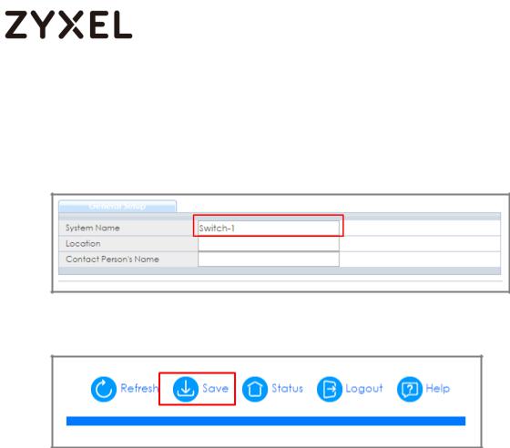
1Enter the web GUI and go to Menu > Basic Setting > General Setup. Change the System Name (Switch-1 in this example) and click Apply.
2 Click “Save” to save the configuration.
13/245
www.zyxel.com
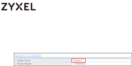
1.2.2 Test the Result
Enter the web GUI and you will see the page of the switch information. Check if the System Name is the name you configured (Switch-1 in this example) or not.
14/245
www.zyxel.com
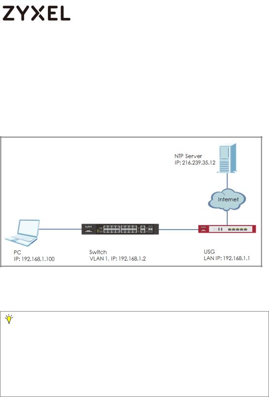
1.3 How to configure the switch to update the time from an NTP server
This example shows administrators how to use the NTP server to update the system time of the switch. As shown below, the PC connects with Switch and Switch connects with the USG in the environment.
Figure 3 Set up Switch to get time from NTP Server
Note:
All network IP addresses and subnet masks are used as examples in this article. Please replace them with your actual network IP addresses and subnet masks. This example was tested using XGS4600-32 (Firmware Version: V4.50). We use google free public NTP server (216.239.35.12) to be our NTP server. You can also choose another available NTP server. Furthermore, due to there is routing set up in this configuration, the user interface might be some difference for other models.
15/245
www.zyxel.com
1.3.1Configuration in Switch
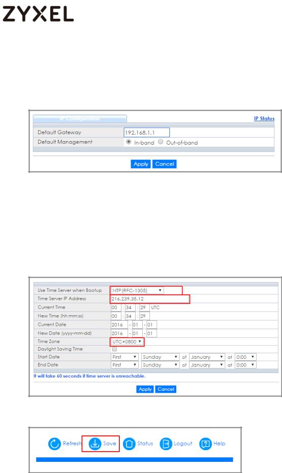
1Enter the web GUI and go to Menu > Basic Setting > IP Setup > IP Configuration. Set the default Gateway as USG IP:
192.168.1.1. Then click “Apply”.
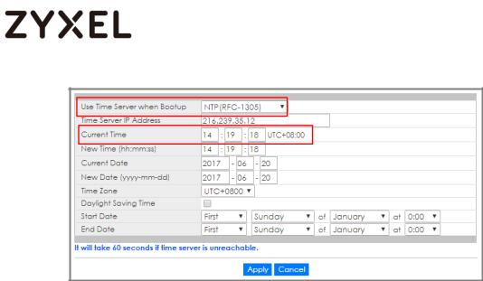
2Go to Menu > Basic Setting > General Setup. Select “Use Time Server when Bootup” to NTP(RFC-1305) and set the “Time Server IP Address”. In this scenario, we use the google free public NTP server (216.239.35.12) as an example. Also, select the “Time Zone” in your location. Finally, remember to click
“Apply”.
3 Click Save to save the configuration.
16/245

www.zyxel.com
1.3.2Test the Result
1Go to Menu > Basic Setting > General Setup. Both the Current Time and Current Date should be the current time in your location. If the current time is not updated as the correct time, click “Refresh”.
2Try to select the “User Time Server when Bootup” as None. Few second later, change back to NTP(RFC-1305). The time will still update to the current time.
17/245
www.zyxel.com
18/245
www.zyxel.com
1.3.3What could go wrong?
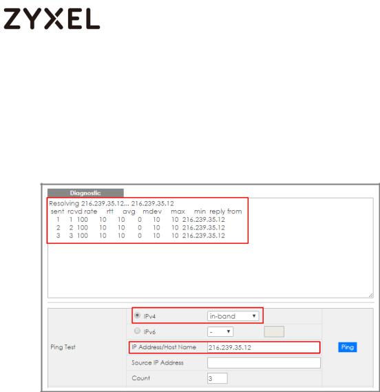
1Switch may not be able to access the NTP Server successfully. Follow the step to test if NTP Server is available. Go to Menu > Management > Diagnostic. Select IPv4 as in-band and type the IP address of NTP Server (216.239.35.12) into the IP Address field. Click “Ping”.
19/245
www.zyxel.com
1.4 How to configure the switch to backup events on a SYSLOG server
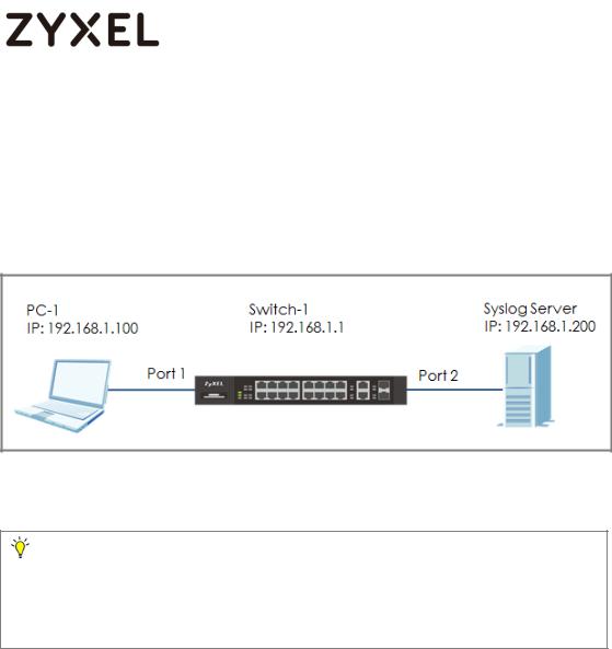
The example shows administrators how to set up the switch to send system log events to a remote syslog server.
Figure 4 Upload the syslog automatically to the server
Note:
All network IP addresses and subnet masks are used as examples in this article. Please replace them with your actual network IP addresses and subnet masks. This example was tested using XGS4600-32 (Firmware Version: V4.50).
20/245
www.zyxel.com
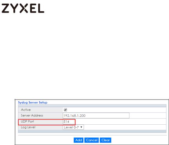
1.4.1Configure the Switch-1
1Enter the web GUI and go to Menu > Management > Syslog Setup > Syslog Server Setup. Activate the syslog server setup and set up the server IP address. In this example, it is 192.168.1.200. Choose the Log Level you prefer (Level 0-7 in this example). The wider the range, the more detailed log will be recorded. Remember to click “Add”.
Note:
Log Level refers to which events should be sent to the Syslog Server. Severity: Emergency (0), Alert (1), Critical (2), Error (3), Warning (4), Notice (5), Informational (6), and Debug (7).
2In the same page, activate the Syslog and activate the logging type you prefer. Also, remember to click “Apply”.
21/245
www.zyxel.com
3 Click Save to save the configuration.
22/245
www.zyxel.com
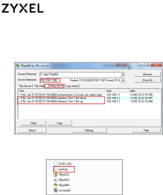
1.4.2 Test the Result
1Unplug and re-plug PC-1 from the switch.
2The Syslog Server should receive an event log from the switch.
3We can also check the directory (“C:\app\Tftpd64” in this example) to find out if a text file is created on the Syslog Server.
23/245
www.zyxel.com
1.4.3What could go wrong?
1If Switch-1 and Syslog Server are in different subnets, remember to set default gateway so that Switch-1 and the Syslog Server can communicate with each other.
2Confirm the service port number of the Switch-1 and the Syslog Server are the same. (Default service port for the Syslog Server in the Switch-1 is 514).
24/245
www.zyxel.com
1.5 How to configure the switch with a port name to quickly identify directly connected devices
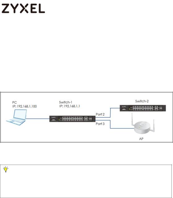
The example shows administrators how to configure the switch with a port name to quickly identify directly connected devices. By doing this, administrators and quickly identify which port connects to which device, location, or section of the network.
Figure 5 Configure the port name of the switch
Note:
All network IP addresses and subnet masks are used as examples in this article. Please replace them with your actual network IP addresses and subnet masks. This example was tested using XGS4600-32 (Firmware Version: V4.50).
25/245
www.zyxel.com
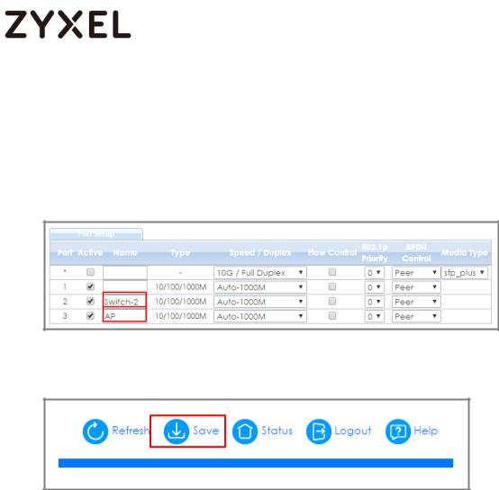
1.5.1Configure Switch-1
1Enter the web GUI and go to Menu > Basic Setting > Port Setup. Type the name of each directly connected devices on the corresponding port name. For example, you can type Switch- 2 in port 2 and AP in port 3. Then click “Apply”.
2 Click Save to save the configuration.
26/245
www.zyxel.com
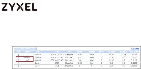
1.5.2Test the Result
1Go to Menu > Maintenance > Port Status. You will see the name you type in the column of name.
27/245
www.zyxel.com
1.6 How to collect the Diagnostic Info
The example shows local administrators how to collect the Diagnostic Info by web GUI. The Diagnostic Info is a set of logs that includes useful information such as System Information, CPU utilization history, system logs and debug reports for issue analysis.
Figure 6 Collect the Diagnostic Info from web GUI
Note:
All network IP addresses and subnet masks are used as examples in this article. Please replace them with your actual network IP addresses and subnet masks. This example was tested using XGS4600-32 (Firmware Version: V4.50).
28/245
www.zyxel.com
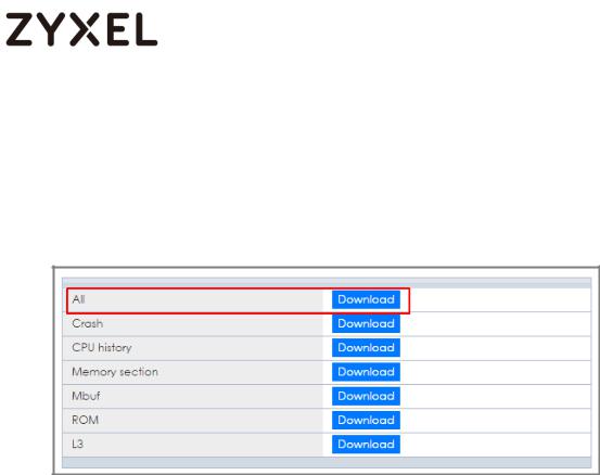
1.6.1Collect the Diagnostic Info from web GUI
1Enter the web GUI and go to Menu > Management > Maintenance > Tech-Support > Click Here. Click the Download button for All. You can also select the specific Diagnostic Info you need. (Ex: Crash, ROM,…..)
29/245
www.zyxel.com
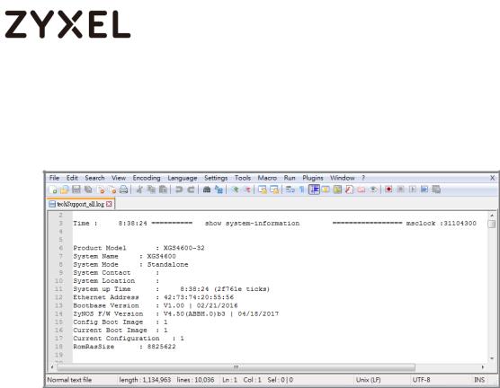
1.6.2Test the Result
1Open the file and you can view the Diagnostic Info. (In this example, we use the Notepad++ to open the .txt file.)
30/245
 Loading...