


IES-6000
Table of contents
 Loading...
IES-6000M
Integrated Ethernet Switch
User’s Guide
Version 1.00
07/2009
Edition 3
www.zyxel.com


About This User's Guide
About This User's Guide
Intended Audience
This manual is intended for people who want to install and maintain the IES-6000 series
Integrated Ethernet Switch.This User’s Guide gives hardware installation, connection and
maintenance instructions. It also gives specifications.
Related Documentation
• Line Card User’s Guides
These User’s Guides provide hardware connection details and explain how to configure
and manage the individual line cards.
• Management Switch Card User’s Guide
This User’s Guide provides hardware connection details, and configuration and
management instructions for the management switch card.
• Supporting Disk
Refer to the included CD for support documents.
• ZyXEL Web Site
Please refer to www.zyxel.com
certifications.
User Guide Feedback
Help us help you. Send all User Guide-related comments, questions or suggestions for
improvement to the following address, or use e-mail instead. Thank you!
The Technical Writing Team,
ZyXEL Communications Corp.,
6 Innovation Road II,
Science-Based Industrial Park,
Hsinchu, 300, Taiwan.
E-mail: techwriters@zyxel.com.tw
for additional support documentation and product
IES-6000M User’s Guide
3

Document Conventions
Document Conventions
Warnings and Notes
These are how warnings and notes are shown in this User’s Guide.
1 Warnings tell you about things that could harm you or your device.
" Notes tell you other important information (for example, other things you may
need to configure or helpful tips) or recommendations.
Naming Conventions
• The IES-6000M is the IES-6000 main chassis. It may be referred to as the “IES-6000M”
or the “main chassis”.
• The IES-3000ST splitter chassis is compatible with the IES-6000. It may be referred to as
the “IES-3000ST” or the “splitter chassis”.
• The IES-3016ST splitter chassis is compatible with the IES-6000. It may be referred to as
the “IES-3016ST” or the “splitter chassis”.
• The MSC1024G (Management Switch Card) may be referred to as the “management
card” or the “MSC”.
• The ALC1248G-51, ALC1248G-53, ALC1272G (ADSL Line Cards), SLC1248G-22
(SHDSL Line Card), VLC1224G-41 (VDSL Line Card) and VOP1248G-61 (VoIP Line
Card) may be collectively referred to as the “line cards”.
• The ALC1248G-51 for ADSL over POTS (Annex A) Line Card may be referred to as the
“ALC1248G”, the “ALC” or the “line card” in this User’s Guide.
• The ALC1248G-53 for ADSL over ISDN (Annex B) Line Card may be referred to as the
“ALC1248G”, the “ALC” or the “line card” in this User’s Guide.
• The ALC1272G ADSL2/2+ Line Card may be referred to as the “ALC1272G”, the
“ALC” or the “line card” in this User’s Guide.
• The SLC1248G SHDSL Line Card may be referred to as the “SLC1248G”, the “SLC” or
the “line card” in this User’s Guide.
• The VLC1224G VDSL Line Card may be referred to as the “VLC1224G”, the “VLC” or
the “line card” in this User’s Guide.
• The VOP1248G-61 VoIP Line Card may be referred to as the “VOP1248G”, the “VOP”,
or the “line card” in this User’s Guide.
• IES-6000 refers to the main chassis and its cards, along with the splitter chassis and its
cards. The IES-6000 may be referred to as the “IES-6000”, the “system”, or the “device”.
4
IES-6000M User’s Guide
Document Conventions
Icons Used in Figures
Figures in this User’s Guide may use the following generic icons. The IES-6000 icon is not an
exact representation of your device.
IES-6000 Computer Notebook computer
Server Telephone
Switch Router
IES-6000M User’s Guide
5

Safety Warnings
Safety Warnings
1 For your safety, be sure to read and follow all warning notices and instructions.
For your safety, be sure to read and follow all warning notices and instructions.
• Do NOT use this product near water, for example, in a wet basement or near a swimming
pool.
• Do NOT expose your device to dampness, dust or corrosive liquids.
• Do NOT store things on the device.
• Do NOT install, use, or service this device during a thunderstorm. There is a remote risk
of electric shock from lightning.
• Warning! Connect the frame ground before you connect any other cables or wiring. Refer
to Appendix A on page 71 for the ground wire gauge.
• Connect ONLY suitable accessories to the device.
• ONLY qualified service personnel should service or disassemble this device.
• Make sure to connect the cables to the correct ports.
• Place connecting cables carefully so that no one will step on them or stumble over them.
• Always disconnect all cables from this device before servicing or disassembling.
• Use ONLY a power wire of the appropriate wire gauge (see Appendix A on page 71 for
details) for your device. Connect it to a power supply of the correct voltage (see Appendix
A on page 71 for details).
• Do NOT allow anything to rest on the power adaptor or cord and do NOT place the
product where anyone can walk on the power adaptor or cord.
• Do NOT use the device if the power adaptor or cord is damaged as it might cause
electrocution.
• If the power adaptor or cord is damaged, remove it from the device and the power source.
• Do NOT attempt to repair the power adaptor or cord. Contact your local vendor to order a
new one.
• Do not use the device outside, and make sure all the connections are indoors. There is a
remote risk of electric shock from lightning.
• CAUTION: RISK OF EXPLOSION IF BATTERY (on the motherboard) IS REPLACED
BY AN INCORRECT TYPE. DISPOSE OF USED BATTERIES ACCORDING TO THE
INSTRUCTIONS. Dispose them at the applicable collection point for the recycling of
electrical and electronic equipment. For detailed information about recycling of this
product, please contact your local city offi ce, your household waste disposal service or the
store where you purchased the product.
• Do NOT obstruct the device ventilation slots, as insufficient airflow may harm your
device.
• Keep the air filters clean, in order to ensure sufficient airflow.
6
IES-6000M User’s Guide
Safety Warnings
• Always cover empty slots with slot covers, to ensure sufficient airflow and reduce the
danger of electric shock.
• Warning! To avoid risk of electric shock, remove only one card at a time and do not place
fingers or objects inside the chassis.
• Use only No. 26 AWG (American Wire Gauge) or larger telecommunication line cord.
• Fuse Warning! Replace a fuse only with a fuse of the same type and rating.
• The length of exposed (bare) power wire should not exceed 10 mm.
• Fan Module Warning! Use the fan module handle when pulling out or pushing in the fan
module. Be careful not to put fingers or objects inside the fan module.
This product is recyclable. Dispose of it properly.
IES-6000M User’s Guide
7

Safety Warnings
8
IES-6000M User’s Guide

Contents Overview
Contents Overview
Introduction ............................................................................................................................19
System Introduction .................................. ... .... ... ... ... .... ... .......................................................... 21
Installation and Connections ................................................................................................25
Hardware Installation and Connections ................................. .................................................... 27
Maintenance and Troubleshooting .......................................................................................57
Maintenance ..............................................................................................................................59
Hardware Troubleshooting ........................................................................................................65
Appendices and Index ...........................................................................................................69
IES-6000M User’s Guide
9

Contents Overview
10
IES-6000M User’s Guide

Table of Contents
Table of Contents
About This User's Guide..........................................................................................................3
Document Conventions............................................................................................................4
Safety Warnings ........................................................................................................................6
Contents Overview ...................................................................................................................9
Table of Contents....................................................................................................................11
List of Figures.........................................................................................................................15
List of Tables...........................................................................................................................17
Part I: Introduction................................................................................. 19
Chapter 1
System Introduction...............................................................................................................21
1.1 System Description ... .... ... ... ... .... ... ... ... .......................................................... .... ... ... ... ... ....... 21
1.2 Applications .................................. ... ... ... .... ... ... ... .... ............................................................. 21
1.2.1 MTU Application .................................................. ... .... ... ... ... ... .... ... ... ... .......................21
1.2.2 Central Office Application ........................................................................................... 22
1.3 Front Panel ............ ... .... .......................................................... ... ... ... .... ................................ 22
Part II: Installation and Connections.................................................... 25
Chapter 2
Hardware Installation and Connections ...............................................................................27
2.1 General Installation Instructions ............................. ... ... .......................................................27
2.2 Main Chassis Installation .....................................................................................................27
2.2.1 Rack-mounted Installation Requirements .................................................................. 27
2.2.2 Mounting the IES-6000M on a Rack .......................................................................... 28
2.2.3 Connecting the Frame Ground ...................... ... ... ... .... ... ... ... ... .... ... ... ... .... ... ... ... ... .......29
2.3 Card Installation ................................................................................................................... 31
2.3.1 Installing MSC and Line Cards ............................ ... .... ... ... ... ... .... ... ... ... .... ... ... ... ... .... ... 31
2.3.2 Removing MSC and Line Cards ................................................................................. 33
2.3.3 Installing a Splitter Chassis Card ............................................................................... 35
IES-6000M User’s Guide
11

Table of Contents
2.3.4 Removing a Splitter Chassis Card ............................................................................. 36
2.4 Making Card Connections ...................................................................................................37
2.4.1 VoIP Line Card Telco-50 Connections ....................................................................... 38
2.4.2 Splitter Chassis Rear Panel Connections (DSL) ........................................................ 40
2.4.3 Splitter Chassis Rear Panel Connections (VoIP) ....................................................... 40
2.4.4 MDF Connections ..... ... .... .......................................................... ... ... .......................... 42
2.4.5 MDF Connections Overview .. ... ... .... .......................................................... ... ... ... .... ... 42
2.4.6 MDF (Main Distribution Frame) .................................................................................. 42
2.4.7 Telco-50 Cables .................................................................................. .... ... ... ... ..........42
2.4.8 MDF Connection Scenarios ................................... .... ... ... ... ... .... ................................ 43
2.4.9 VoIP Connection Scenarios .......................................... ... ... ... .... ... ... ... .... ... ................48
2.5 Alarm Module ........ ... .... ... ... ... .... ... ... ... .......................................................... .... ... ... ... .......... 51
2.5.1 Installing the Alarm Module . ... ... ... .............................................................. ... ... ... .... ... 51
2.5.2 Removing the Alarm Module ...................................................................................... 51
2.5.3 Alarm Connections ................................................. .... ... ... ... ... .... ... ... ... ....................... 52
2.6 Power Connections ................................................................... ... ... .................................... 53
2.6.1 Power Modules ............ .... ... ... ... ... .... ... .......................................................... ... ... .... ... 53
2.7 Dressing the Power Wires and Alarm Cable .......................................................................55
2.7.1 Procedure to Turn on the IES-6000 Power ......................... ... .... ... ... ... .... ... ... ... ... .... ... 55
Part III: Maintenance and Troubleshooting ......................................... 57
Chapter 3
Maintenance............................................................................................................................59
3.1 Fan Maintenance ................................................ ................................................................. 59
3.1.1 Procedure to Remove and Install the Fan Module ........................................ .............59
3.1.2 Procedure to Remove and Install the Filters ..............................................................60
3.2 Power Maintenance ............................................ ................................................................. 62
3.2.1 Procedure to Disconnect the Power ....................... .... ... ... ... ....................................... 62
3.2.2 Procedure to Change a Power Module ......................................................................62
3.2.3 Procedure to Reconnect the Power ........................................................................... 63
Chapter 4
Hardware Troubleshooting ....................................................................................................65
4.1 The PWR LED Does Not Turn On or Is Blinking ................................................................. 65
4.2 The ALM LED Is On ............................................................................................................65
4.3 No Voice on an ADSL Connection ....................................................................................... 65
4.4 No Voice on a VoIP Connection .......................................................................................... 66
4.5 Testing Wiring ..................... ... .... ... ... .......................................................... ... .... ... ... .............66
12
IES-6000M User’s Guide

Table of Contents
Part IV: Appendices and Index ............................................................. 69
Appendix A Product Specifications.........................................................................................71
Appendix B Legal Information ................................................................................................75
Appendix C Customer Support...............................................................................................79
Index.........................................................................................................................................83
IES-6000M User’s Guide
13

Table of Contents
14
IES-6000M User’s Guide

List of Figures
List of Figures
Figure 1 Application: Multi-tenant Unit (MTU) ........................................................................................22
Figure 2 Application: Central Office ........................................................................................................22
Figure 3 IES-6000M Front Panel ............................................................................................................23
Figure 4 Main Chassis Airflow ................................................................................................................ 28
Figure 5 Attaching Mounting Brackets to the Main Chassis ...................................................................29
Figure 6 Main Chassis Frame Ground ...................................................................................................30
Figure 7 Splitter Chassis Frame Ground ................................................................................................ 30
Figure 8 Installing a Card ....................................................................................................................... 31
Figure 9 Closing the Ejector Levers ....................................................................................................... 32
Figure 10 Tightening Card Thumbscrews ..................................................... ...... ....... ...... ....... ...... ... ....... 32
Figure 11 Loosening Card Thumbscrews ...............................................................................................33
Figure 12 Opening the Ejector Levers ................................... .................................................... .............34
Figure 13 Removing a Main Chassis Card ...................................... ... .... ... ............................................. 34
Figure 14 Installing a Splitter Chassis Card ............................................................................................ 35
Figure 15 Tightening Splitter Chassis Card Thumbscrews ..................................................................... 36
Figure 16 Loosening Splitter Chassis Card Thumbscrews .....................................................................36
Figure 17 Removing a Splitter Chassis Card .......................................................................................... 37
Figure 18 IES-6000 Front Panel Telco-50 Connections (2 Splitter Chassis) .......................................... 38
Figure 19 IES-6000 DSL and VoIP Front Panel Telco-50 Connections (2 Splitter Chassis) ........... .... ... 39
Figure 20 IES-6000 DSL and VoIP Rear Panel Telco-50 Connections (2 Splitter Chassis) ...................41
Figure 21 MDF (Main Distribution Frame) Wiring ................................................................................... 42
Figure 22 Telco-50 Cable with RJ-11 Connectors ..................................................................................43
Figure 23 Installation Overview Example ...............................................................................................44
Figure 24 Installation Scenario A ............................................................................................................ 45
Figure 25 One MDF for End-user and CO Connections .........................................................................45
Figure 26 Installation Scenario B ............................................................................................................ 46
Figure 27 Two Separate MDFs for End-user and CO Connections .......................................... ... ... .... ... 47
Figure 28 Installation Scenario C ........................................................................................................... 48
Figure 29 VoIP Connection Scenario A .................................................................................................. 49
Figure 30 VoIP Connection Scenario B .................................................................................................. 50
Figure 31 Installing the Alarm Module .................................................................................................... 51
Figure 32 Removing the Alarm Module .................................................................................................. 52
Figure 33 ALARM Connector Pin Layout .............................................................................................. 52
Figure 34 Sliding Out the IES-6000 Power Module ................................................................................54
Figure 35 Connecting the Power Wires to the IES-6000 Power Module ............................................... 54
Figure 36 Dressing the Power Wires and Alarm Cable .... .......................................................... ... .......55
Figure 37 Loosen the Thumbscrews on the IES-6000 Fan Module ............................................. ..........59
Figure 38 Remove the IES-6000 Fan Module ........................................................................................60
IES-6000M User’s Guide
15

List of Figures
Figure 39 IES-6000 Fan Module (Location of Fuse Indicated) ...............................................................60
Figure 40 Loosen the Thumbscrews on the IES-6000 Air Filter ...................................... .... ... ... .............61
Figure 41 Remove the IES-6000 Air Filters ........................................ .... ... ............................................. 61
Figure 42 Sliding Out the IES-6000 Power Module ................................................................................62
Figure 43 Connecting the Power Wires to the IES-6000 Power Module ............................................... 63
Figure 44 Testing In-house Wiring .......................................................................................................... 67
16
IES-6000M User’s Guide

List of Tables
List of Tables
Table 1 PWR LED Troubleshooting ....................................................................................................... 65
Table 2 Voice Troubleshooting ...............................................................................................................65
Table 3 Testing In-house Wiring ............................................................................................................67
Table 4 Features ....................................................................................................................................71
IES-6000M User’s Guide
17

List of Tables
18
IES-6000M User’s Guide

PART I
Introduction
System Introduction (21)
19

20

CHAPTER 1
System Introduction
This chapter describes the system features, specifications and applications of the IES-6000.
1.1 System Description
The IES-6000 is an IP-based DSLAM (Digital Subscriber Line Access Multiplexer) that
connects subscribers to the Internet. As a high-performance yet compact platform, it
conveniently gives telephone companies and Internet Service Providers (ISPs) the ability to
deliver broadband Internet access and voice services to subscribers.
The IES-6000 platform allows for convenient management and support of various
technologies. The IES-6000M can hold a maximum of sixteen line cards, so up to 768
subscribers (1152 when using the ALC1272 72-port line card) can simultaneously utilize a
wide range of powerful broadband services. Additionally, the line cards are hot-swappable;
thus, you do not need to interrupt the service of other cards to change or service an individual
card. A single management switch card can provide the convenience of centralized network
traffic supervision.
The IES-6000 also has dual, hot-swappable power modules that reduce the chance of system
shutdown.
1.2 Applications
These are the main applications for the IES-6000:
• Internet access, Voice over IP and multimedia services for Multiple Tenant Units (MTU).
• Other applications include video services, telemedicine, surveillance systems, remote
servers systems, cellular base stations and high-quality videoconferencing.
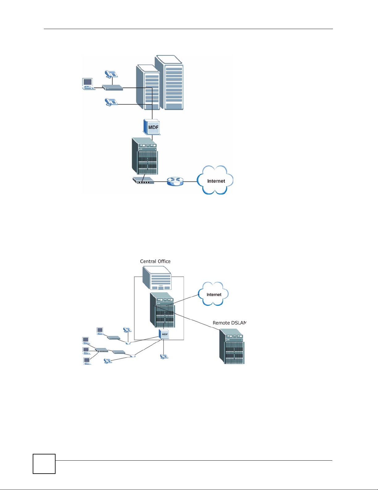
1.2.1 MTU Application
The following diagram depicts a typical application of the IES-6000 in a large residential
building or multiple tenant unit (MTU). This application leverages existing phone line wiring
to provide voice service and Internet access (with DSL modems) to all tenants. The MDF is
the point of termination for the outside telephone company lines coming into a building and
the telephone wiring in the building. Note that ADSL service can co-exist with voice service
on the same line.
IES-6000M User’s Guide
21
Chapter 1 System Introduction
Figure 1 Application: Multi-tenant Unit (MTU)
1.2.2 Central Office Application
The IES-6000 provides DSL and voice service over telephone wires to subscribers. The
following figure shows the IES-6000 setup in a telephone company’s central office.
Figure 2 Application: Central Office
1.3 Front Panel
22
The following figures show the front panel of the IES-6000M with cards installed.
IES-6000M User’s Guide
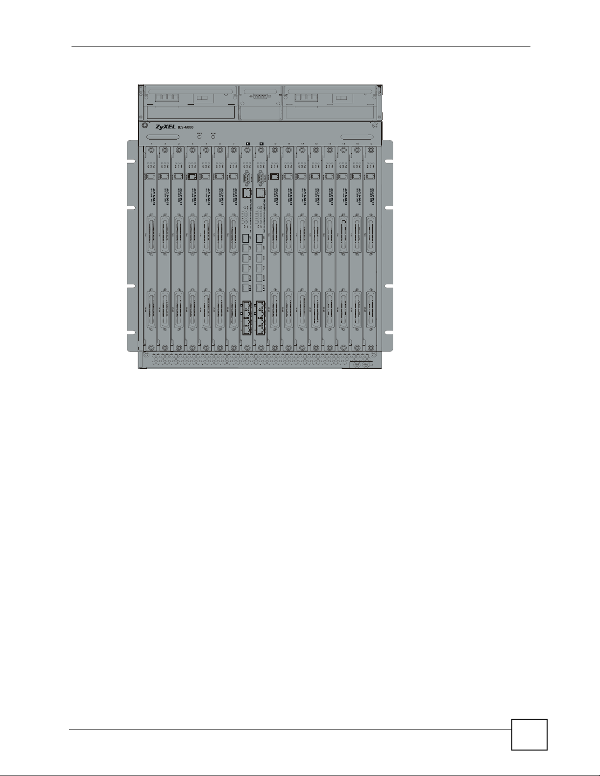
Figure 3 IES-6000M Front Panel
Chapter 1 System Introduction
IES-6000M User’s Guide
23

Chapter 1 System Introduction
24
IES-6000M User’s Guide

PART II
Installation and
Connections
Hardware Installation and Connections (27)
25

26

CHAPTER 2
Hardware Installation and
Connections
This chapter describes how to install and connect the IES-6000M and line cards.
2.1 General Installation Instructions
Perform the installation as follows:
• Make sure the IES-6000’s power switches are in the OFF position.
• Install the main chassis as detailed in this chapter. Make sure you connect the frame
grounds before you make any other connections.
• If line cards are not already installed, follow the procedure in the next section to install
them.
•Refer to Section 2.4.4 on page 44 for instructions on making connections with Telco-50
connectors.
•Refer to Section 2.5 on page 53 for instructions on making alarm connections.
•Refer to Section 2.6 on page 55 for instructions on making power connections and turning
on the IES-6000.
2.2 Main Chassis Installation
This section explains how to install the main chassis on a rack. If you are installing the main
chassis without a splitter chassis, you can install the main chassis on a desktop instead.
2.2.1 Rack-mounted Installation Requirements
Make sure the rack will safely support the combined weight of all the equipment it contains.
• Use a #2 Phillips screwdriver to install the screws.
•Refer to Appendix A on page 71 for the gauge of wire to use for the frame ground
connections.
•Refer to Appendix A on page 71 for the IES-600M’s dimensions, weights and power
consumption.
IES-6000M User’s Guide
27
Loading...