


 Loading...
GS1910/XGS1910 Series
GbE Smart Managed Switch
Default Login Details |
IMPORTANT! |
||
|
|
|
|
IP Address |
http://192.168.1.1 |
READ CAREFULLY |
|
User Name |
admin |
||
BEFORE USE. |
|||
Password |
1234 |
||
|
|||
|
|
KEEP THIS GUIDE |
|
|
|
||
|
|
FOR FUTURE |
|
Version 1.00 |
|
REFERENCE. |
|
Edition 1, 05/2012 |
|
||
www.zyxel.com
Copyright © 2012
ZyXEL Communications Corporation

IMPORTANT!
READ CAREFULLY BEFORE USE.
KEEP THIS GUIDE FOR FUTURE REFERENCE.
Note: This guide is a reference for a series of products. Therefore some features or options in this guide may not be available in your product.
Graphics in this book may differ slightly from the product due to differences in operating systems, operating system versions, or if you installed updated firmware/software for your device. Every effort has been made to ensure that the information in this manual is accurate.
Related Documentation
•Web Configurator Online Help
Click the help icon in any screen for help in configuring that screen and supplementary information.
2 |
|
GS1910/XGS1910 Series User’s Guide |
|
|
|

|
|
Table of Contents |
|
|
|
|
|
Table of Contents |
Table of Contents ................................................................................................................................. |
3 |
|
Chapter |
1 |
|
Getting to Know Your Switch............................................................................................................... |
5 |
|
1.1 |
Introduction ......................................................................................................................................... |
5 |
|
1.1.1 Bridging Example ...................................................................................................................... |
5 |
|
1.1.2 High Performance Switching Example ...................................................................................... |
6 |
|
1.1.3 Gigabit Ethernet to the Desktop ................................................................................................ |
7 |
|
1.1.4 IEEE 802.1Q VLAN Application Example .................................................................................. |
7 |
|
1.1.5 IPv6 Support .............................................................................................................................. |
8 |
1.2 |
Ways to Manage the Switch ................................................................................................................ |
8 |
1.3 |
Good Habits for Managing the Switch ................................................................................................. |
8 |
Chapter 2 |
|
|
Hardware Installation and Connection ............................................................................................. |
11 |
|
2.1 |
Freestanding Installation .................................................................................................................. |
11 |
2.2 |
Mounting the Switch on a Rack ........................................................................................................ |
12 |
|
2.2.1 Rack-mounted Installation Requirements ................................................................................ |
12 |
|
2.2.2 Attaching the Mounting Brackets to the Switch ....................................................................... |
12 |
|
2.2.3 Mounting the Switch on a Rack ............................................................................................... |
13 |
Chapter 3 |
|
|
Hardware Overview ............................................................................................................................ |
15 |
|
3.1 |
Front Panel Connections .................................................................................................................. |
15 |
|
3.1.1 Ethernet Ports .......................................................................................................................... |
17 |
|
3.1.2 Dual Personality Interfaces ...................................................................................................... |
18 |
|
3.1.3 SFP/SFP+ Slots ...................................................................................................................... |
18 |
|
3.1.4 Console Port ........................................................................................................................... |
20 |
3.2 |
Rear Panel ........................................................................................................................................ |
20 |
|
3.2.1 Power Connector ..................................................................................................................... |
21 |
3.3 |
LEDs ............................................................................................................................................. |
22 |
Chapter |
4 |
|
The Web Configurator ........................................................................................................................ |
25 |
|
4.1 |
Introduction ....................................................................................................................................... |
25 |
4.2 |
System Login ................................................................................................................................. |
25 |
4.3 |
The Web Configurator Layout ......................................................................................................... |
26 |
|
4.3.1 Change Your Password ........................................................................................................ |
32 |
4.4 |
Switch Lockout ................................................................................................................................ |
32 |
GS1910/XGS1910 Series User’s Guide
3 |

Table of Contents
4.5 |
Logging Out of the Web Configurator .............................................................................................. |
32 |
4.6 |
Help .................................................................................................................................................. |
32 |
Chapter |
5 |
|
Tutorials............................................................................................................................................... |
|
33 |
5.1 |
How to Change Switch Management IP Address ............................................................................. |
33 |
5.2 |
How to Configure Login Accounts and Privilege Levels .................................................................... |
34 |
5.3 |
How to Manage a Configuration File ................................................................................................. |
36 |
|
5.3.1 Backing up a Configuration File ............................................................................................... |
36 |
|
5.3.2 Restoring a Configuration File ................................................................................................. |
37 |
5.4 |
How to Create a VLAN ...................................................................................................................... |
38 |
|
5.4.1 Setting Port VID ....................................................................................................................... |
39 |
5.5 |
How to Set Up a Guest VLAN with IEEE 802.1x Authentication ....................................................... |
41 |
|
5.5.1 Creating a VLAN for Port which is not IEEE 802.1x enabled .................................................. |
41 |
|
5.5.2 Enabling IEEE 802.1x Port Authentication and Guest VLAN .................................................. |
42 |
5.6 |
How to Use Private VLAN to Do Port Isolation in a VLAN ................................................................ |
44 |
|
5.6.1 Creating a Private VLAN ......................................................................................................... |
44 |
|
5.6.2 Enabling Port Isolation ............................................................................................................. |
45 |
5.7 |
How to Use IP Source Guard and DHCP Snooping to Prevent Spoofed Traffic ............................... |
45 |
5.8 |
How to Use DHCP Relay on the Switch ............................................................................................ |
48 |
|
5.8.1 Creating a VLAN ...................................................................................................................... |
49 |
|
5.8.2 Configuring DHCP Relay ......................................................................................................... |
49 |
|
5.8.3 Troubleshooting ....................................................................................................................... |
50 |
5.9 |
How to Use Link Aggregation to Group Multiple Ports into One Logical Link ................................... |
50 |
|
5.9.1 Static Port Trunking ................................................................................................................. |
50 |
|
5.9.2 Dynamic Port Trunking ............................................................................................................ |
51 |
5.10 How to Analyze Traffic Using Mirroring ........................................................................................... |
52 |
|
|
5.10.1 Configuring Mirroring ............................................................................................................. |
53 |
|
5.10.2 Configuring Remote Port Mirroring ........................................................................................ |
54 |
5.11 How to Use IGMP Snooping to Reduce Multicast Traffic Passing through your Switch ................. |
60 |
|
5.12 How to Configure Access Control List (ACL) for Packets Filtering ................................................. |
63 |
|
5.13 How to Reset the Switch via the Console Port ................................................................................ |
66 |
|
Chapter |
6 |
|
Troubleshooting.................................................................................................................................. |
69 |
|
6.1 |
Power, Hardware Connections, and LEDs ........................................................................................ |
69 |
6.2 |
Switch Access and Login .................................................................................................................. |
70 |
Appendix |
A Legal Information............................................................................................................ |
73 |
Index .................................................................................................................................................... |
|
75 |
4 |
GS1910/XGS1910 Series User’s Guide

1
Getting to Know Your Switch
This chapter introduces the main features and applications of the Switch.
1.1 Introduction
Your Switch is a Gigabit Ethernet (GbE) switch with 20, 44 or 48 10/100/1000 Mbps Ethernet ports. The GS1910-24, GS1910-24HP, XGS1910-24 or XGS1910-48 also has four GbE dual personality interfaces. A dual personality interface includes one Gigabit Ethernet port and one slot for a miniGBIC transceiver (SFP module) with one port active at a time. The GS1910-48 and GS1910-48HP have four SFP slots.
The Ethernet ports on the GS1910-24HP or GS1910-48HP are all IEEE802.3at High Power over Ethernet (PoE) compliant and can supply power of up to 30W per Ethernet port.
The XGS1910-24 or XGS1910-48 is stackable and provides two or four SFP+ slots for uplink or stacking. They can operate together with other XGS1910-24 or XGS1910-48 switches and need to be directly connected for stacking. The configurations are done on the master switch, which then maintains and manages the slave switches in the stack. You can stack up to eight XGS1910-24 or XGS1910-48 switches per stack.
With its built-in web configurator, managing and configuring the Switch is easy. In addition, the Switch can also be managed via third-party SNMP management.
1.1.1 Bridging Example
In this example the Switch connects different company departments (RD and Sales) to the corporate backbone. It can alleviate bandwidth contention and eliminate server and network bottlenecks. All users that need high bandwidth can connect to high-speed department servers via
GS1910/XGS1910 Series User’s Guide
5 |
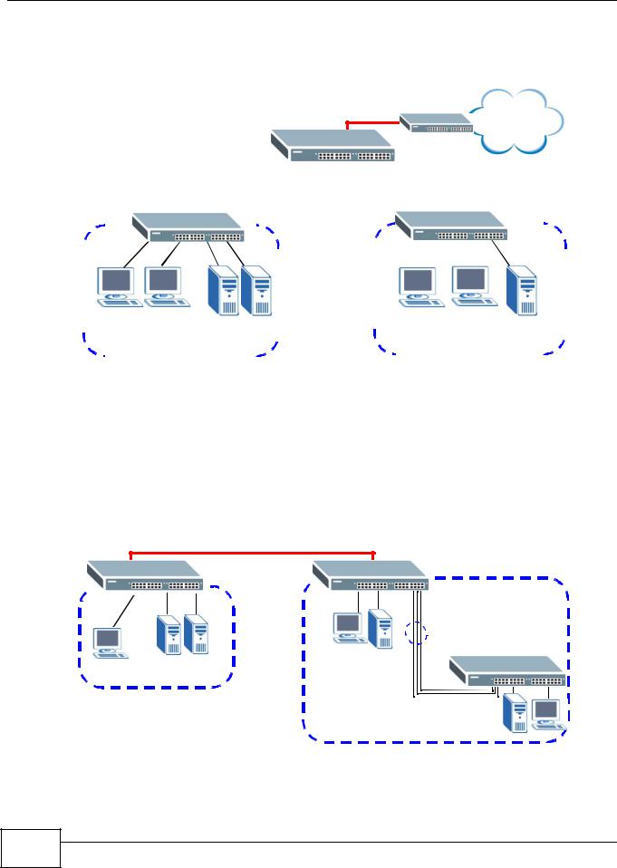
Chapter 1 Getting to Know Your Switch
the Switch. You can provide a super-fast uplink connection by using the optional 10 Gigabit uplink module on the Switch.
Figure 1 Bridging Application
Backbone
|
|
|
|
|
|
|
|
|
|
|
|
|
|
|
|
|
|
|
|
|
|
|
|
|
|
|
|
|
|
|
|
|
|
|
|
|
|
|
|
|
|
|
|
|
|
|
|
|
|
|
|
|
|
|
|
|
|
|
|
|
|
|
|
|
|
|
|
|
|
|
|
|
|
|
|
|
|
|
|
|
|
|
|
|
|
|
|
|
|
|
|
|
|
|
|
|
|
|
|
|
|
|
|
|
|
|
|
|
|
|
|
|
|
|
|
|
|
|
|
|
|
|
|
|
|
|
|
|
|
|
|
|
|
|
|
|
|
|
|
|
|
|
|
|
|
|
|
|
|
|
|
|
|
|
|
|
|
|
|
|
|
|
|
|
|
|
|
|
|
|
|
|
|
|
|
|
|
|
|
|
|
|
|
|
|
|
|
|
|
|
|
|
|
|
|
|
|
|
|
|
|
|
|
|
|
|
|
|
|
|
|
|
|
|
|
|
|
|
|
|
|
|
|
|
|
|
|
|
|
|
|
|
|
|
|
|
|
|
|
|
|
|
|
|
|
|
|
|
|
|
|
|
|
|
|
|
|
|
|
|
|
|
|
|
|
|
|
|
|
|
|
|
|
|
|
|
|
|
|
|
|
|
|
|
|
|
|
|
|
|
|
|
|
|
|
|
|
|
|
|
|
|
|
|
|
|
|
|
|
|
|
|
|
|
|
|
|
|
|
|
|
|
|
|
|
|
|
|
|
|
|
|
|
|
|
|
|
|
|
|
|
|
|
|
|
|
|
|
|
|
|
|
|
|
|
|
|
|
|
|
|
|
|
|
|
|
|
|
|
|
|
|
|
|
|
|
|
|
|
|
|
|
|
|
|
|
|
|
|
|
|
|
|
|
|
|
|
|
|
|
|
|
|
|
|
|
|
|
|
|
|
|
|
|
|
|
|
|
|
|
|
|
|
|
|
|
|
|
|
|
|
|
|
|
|
|
|
|
|
|
|
|
|
|
|
|
|
|
|
|
|
|
|
|
|
|
|
|
|
|
|
|
|
|
|
|
|
|
|
|
|
|
|
|
|
|
|
|
|
|
|
|
|
|
|
|
|
|
|
|
|
|
|
|
|
|
|
|
|
|
|
|
|
|
|
|
|
|
|
|
|
|
|
|
|
|
|
|
|
|
|
|
|
|
|
|
|
|
|
|
|
|
|
|
|
|
|
|
|
|
|
|
|
|
|
|
|
|
|
|
|
|
|
|
|
|
|
|
|
|
|
|
|
|
|
|
|
|
|
|
|
|
|
|
|
|
|
|
|
|
|
|
|
|
|
|
|
|
|
|
|
|
|
|
|
|
|
|
|
|
|
|
|
|
|
|
|
|
|
|
|
|
|
|
|
|
|
|
|
|
|
|
|
|
|
|
|
|
|
|
|
|
|
|
|
|
|
|
|
|
|
|
|
|
|
|
|
|
|
|
|
|
|
|
|
|
|
|
|
|
|
|
|
|
|
|
|
|
|
|
|
|
|
|
|
|
|
|
|
|
|
|
|
|
|
|
|
|
|
|
|
|
|
|
|
|
|
|
|
|
|
|
|
|
|
|
|
|
|
|
|
|
|
|
|
|
|
|
|
|
|
|
|
|
|
|
|
|
|
|
|
|
|
|
|
|
|
|
|
|
|
|
|
|
|
|
|
|
|
|
|
|
|
|
|
|
|
|
|
|
|
|
|
|
|
|
|
|
|
|
|
|
|
|
|
|
|
|
|
|
|
|
|
|
|
|
|
|
|
|
|
|
|
|
|
|
|
|
|
|
|
|
|
|
|
|
|
|
|
|
|
|
|
|
|
|
|
|
|
|
|
|
|
|
|
|
|
|
|
|
|
|
|
|
|
|
|
|
|
|
|
|
|
|
|
|
Sales |
|
|
|
|
|
|
|
|
|
|
|
|
|
|
|
|
|
|
|
|
|
|
|
|
|
|
|
|
|
|
|
|
||||||||
|
|
|
|
|
|
|
|
|
|
|
|
|
|
|
|
|
|
|
|
|
|
|
|
|
|
|
|
|
|
|
|
|
|
|
|
|
|
|
|
|
|
|
|
|
|
|
|
|
|
|
|
|
|
|
|
|
|
|
|
|
|
|
|
|
|||||||||
|
|
|
|
|
|
|
|
|
|
|
|
|
|
|
|
|
|
|
|
|
|
|
|
|
|
|
|
|
|
|
|
|
|
|
|
|
|
|
|
|
|
|
|
|
|
|
|
|
|
|
|
|
|
|
|
|
|
|
|
|
|
|
|
|
|||||||||
|
|
|
|
|
|
|
|
|
|
|
|
|
|
|
|
|
|
|
|
|
|
|
|
|
|
|
|
|
|
|
|
|
|
|
|
|
|
|
|
|
|
|
|
|
|
|
|
|
|
|
|
|
|
|
|
|
|
|
|
|
|
|
|
|
|||||||||
|
|
|
|
|
|
|
|
|
|
|
|
|
|
|
|
|
|
|
|
|
|
|
|
|
|
|
|
|
|
|
|
|
|
|
|
|
|
|
|
|
|
|
|
|
|
|
|
|
|
|
|
|
|
|
|
|
|
|
|
|
|
|
|
|
|||||||||
|
|
|
|
|
|
|
|
|
|
|
|
|
|
|
|
|
|
|
|
|
|
|
|
|
|
|
|
|
|
|
|
|
|
|
|
|
|
|
|
|
|
|
|
|
|
|
|
|
|
|
|
|
|
|
|
|
|
|
|
|
|
|
|
|
|||||||||
|
|
|
|
|
|
|
|
|
|
|
|
|
|
|
|
|
|
|
|
|
|
|
|
|
|
|
|
|
|
|
|
|
|
|
|
|
|
|
|
|
|
|
|
|
|
|
|
|
|
|
|
|
|
|
|
|
|
|
|
|
|
|
|
|
|||||||||
|
|
|
|
|
|
|
|
|
|
|
|
|
|
|
|
|
|
|
|
|
|
|
|
|
|
|
|
|
|
|
|
|
|
|
|
|
|
|
|
|
|
|
|
|
|
|
|
|
|
|
|
|
|
|
|
|
|
|
|
|
|
|
|
|
|||||||||
|
|
|
|
|
|
|
|
|
|
|
|
|
|
|
|
|
|
|
|
|
|
|
|
|
|
|
|
|
|
|
|
|
|
|
|
|
|
|
|
|
|
|
|
|
|
|
|
|
|
|
|
|
|
|
|
|
|
|
|
|
|
|
|
|
|||||||||
|
|
|
|
RD |
|
|
|
|
|
|
|
|
|
|
|
|
|
|
|
|
|
|
|
|
|
|
|
|
|
|
|
|
|
|
|
|
|
|
|
|
|||||||||||||||||||||||||||||||||
|
|
|
|
|
|
|
|
|
|
|
|
|
|
|
|
|
|
|
|
|
|
|
|
|
|
|
|
|
|
|
|
|
|
|
|
|
|
|
|
||||||||||||||||||||||||||||||||||
|
|
|
|
|
|
|
|
|
|
|
|
|
|
|
|
|
|
|
|
|
|
|
|
|
|
|
|
|
|
|
|
|
|
|
|
|
|
|
|
||||||||||||||||||||||||||||||||||
|
|
|
|
|
|
|
|
|
|
|
|
|
|
|
|
|
|
|
|
|
|
|
|
|
|
|
|
|
|
|
|
||||||||||||||||||||||||||||||||||||||||||
|
|
|
|
|
|
|
|
|
|
|
|
|
|
|
|
|
|
|
|
|
|
|
|
|
|
|
|
|
|
|
|
|
|
|
|
|
|||||||||||||||||||||||||||||||||||||
|
|
|
|
|
|
|
|
|
|
|
|
|
|
|
|
|
|
|
|
|
|
|
|
|
|
|
|
|
|
|
|
|
|
|
|
|
|
|
|
|
|
|
|
|
|
|
|
|
|
|
|
|
|
|
|
|
|
|
|
|
|
|
|
|
|
|
|
|
|
|
|
|
|
1.1.2 High Performance Switching Example
The Switch is ideal for connecting two geographically dispersed networks that need high bandwidth. In the following example, a company uses the optional 10 Gigabit uplink modules to connect the headquarters to a branch office network. Within the headquarters network, a company can use trunking to group several physical ports into one logical higher-capacity link. Trunking can be used if for example, it is cheaper to use multiple lower-speed links than to under-utilize a high-speed, but more costly, single-port link.
Figure 2 High Performance Switching
10 Gbps
Trunk |
Branch
HQ
6 |
GS1910/XGS1910 Series User’s Guide
Chapter 1 Getting to Know Your Switch
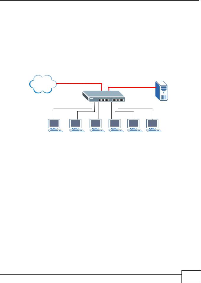
1.1.3 Gigabit Ethernet to the Desktop
The Switch is an ideal solution for small networks which demand high bandwidth for a group of heavy traffic users. You can connect computers and servers directly to the Switch’s port or connect other switches to the Switch. Use the optional 10 Gigabit uplink module to provide high speed access to a data server and the Internet. The uplink module supports a fiber-optic connection which alleviates the distance limitations of copper cabling.
In this example, all computers can share high-speed applications on the server and access the Internet. To expand the network, simply add more networking devices such as switches, routers, computers, print servers and so on.
Figure 3 Gigabit to the Desktop
Internet
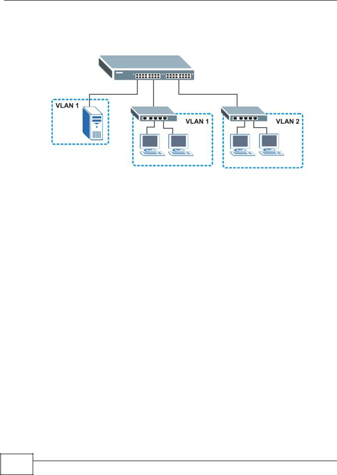
1.1.4 IEEE 802.1Q VLAN Application Example
A VLAN (Virtual Local Area Network) allows a physical network to be partitioned into multiple logical networks. Stations on a logical network belong to one or more groups. With VLAN, a station cannot directly talk to or hear from stations that are not in the same group(s) unless such traffic first goes through a router.
For more information on VLANs, refer to Chapter 9 on page 111.
1.1.4.1 Tag-based VLAN Example
Ports in the same VLAN group share the same frame broadcast domain, thus increasing network performance by reducing broadcast traffic. VLAN groups can be modified at any time by adding, moving or changing ports without any re-cabling.
GS1910/XGS1910 Series User’s Guide
7 |
Chapter 1 Getting to Know Your Switch
Shared resources such as a server can be used by all ports in the same VLAN as the server. In the following figure only ports that need access to the server need to be part of VLAN 1. Ports can belong to other VLAN groups too.
Figure 4 Shared Server Using VLAN Example
1.1.5 IPv6 Support
IPv6 (Internet Protocol version 6), is designed to enhance IP address size and features. The increase in IPv6 address size to 128 bits (from the 32-bit IPv4 address) allows up to 3.4 x 1038 IP addresses. At the time of writing, the Switch supports the following features.
•Static address assignment and stateless auto-configuration
•Neighbor Discovery Protocol (a protocol used to discover other IPv6 devices in a network)
•Remote Management using ping SNMP, telnet and HTTP services
•ICMPv6 to report errors encountered in packet processing and perform diagnostic functions, such as "ping”
•IPv4/IPv6 dual stack; the Switch can run IPv4 and IPv6 at the same time
•Multicast Listener Discovery (MLD) snooping and proxy
1.2Ways to Manage the Switch
Use any of the following methods to manage the Switch.
•Web Configurator. This is recommended for everyday management of the Switch using a (supported) web browser.
•SNMP. The device can be monitored and/or managed by an SNMP manager.
1.3Good Habits for Managing the Switch
Do the following things regularly to make the Switch more secure and to manage the Switch more effectively.
8 |
GS1910/XGS1910 Series User’s Guide

Chapter 1 Getting to Know Your Switch
•Change the password. Use a password that’s not easy to guess and that consists of different types of characters, such as numbers and letters.
•Write down the password and put it in a safe place.
•Back up the configuration (and make sure you know how to restore it). Restoring an earlier working configuration may be useful if the device becomes unstable or even crashes. If you forget your password, you will have to reset the Switch to its factory default settings. If you backed up an earlier configuration file, you would not have to totally re-configure the Switch. You could simply restore your last configuration.
GS1910/XGS1910 Series User’s Guide
9 |

Chapter 1 Getting to Know Your Switch
10 |
GS1910/XGS1910 Series User’s Guide
2
Hardware Installation and
Connection
This chapter shows you how to install and connect the Switch.
2.1 Freestanding Installation
1Make sure the Switch is clean and dry.
2Set the Switch on a smooth, level surface strong enough to support the weight of the Switch and the connected cables. Make sure there is a power outlet nearby.
3Make sure there is enough clearance around the Switch to allow air circulation and the attachment of cables and the power cord.
4Remove the adhesive backing from the rubber feet.
5Attach the rubber feet to each corner on the bottom of the Switch. These rubber feet help protect the Switch from shock or vibration and ensure space between devices when stacking.
Figure 5 Attaching Rubber Feet
|
11 |
GS1910/XGS1910 Series User’s Guide |
|
|
|

Chapter 2 Hardware Installation and Connection
Note: Do NOT block the ventilation holes. Leave space between devices when stacking.
Note: For proper ventilation, allow at least 4 inches (10 cm) of clearance at the front and 3.4 inches (8 cm) at the back of the Switch. This is especially important for enclosed rack installations.
2.2 Mounting the Switch on a Rack
This section lists the rack mounting requirements and precautions and describes the installation steps.
2.2.1Rack-mounted Installation Requirements
•Two mounting brackets.
•Eight M3 flat head screws and a #2 Philips screwdriver.
•Four M5 flat head screws and a #2 Philips screwdriver.
Failure to use the proper screws may damage the unit.
2.2.1.1Precautions
•Make sure the rack will safely support the combined weight of all the equipment it contains.
•Make sure the position of the Switch does not make the rack unstable or topheavy. Take all necessary precautions to anchor the rack securely before installing the unit.
2.2.2Attaching the Mounting Brackets to the Switch
1Position a mounting bracket on one side of the Switch, lining up the four screw holes on the bracket with the screw holes on the side of the Switch.
Figure 6 Attaching the Mounting Brackets
12 |
|
|
GS1910/XGS1910 Series User’s Guide |
|
|
|
|
|
Chapter 2 Hardware Installation and Connection
2Using a #2 Philips screwdriver, install the M3 flat head screws through the mounting bracket holes into the Switch.
3Repeat steps 1 and 2 to install the second mounting bracket on the other side of the Switch.
4You may now mount the Switch on a rack. Proceed to the next section.
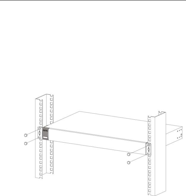
2.2.3Mounting the Switch on a Rack
1Position a mounting bracket (that is already attached to the Switch) on one side of the rack, lining up the two screw holes on the bracket with the screw holes on the side of the rack.
Figure 7 Mounting the Switch on a Rack
2Using a #2 Philips screwdriver, install the M5 flat head screws through the mounting bracket holes into the rack.
3Repeat steps 1 and 2 to attach the second mounting bracket on the other side of the rack.
|
13 |
GS1910/XGS1910 Series User’s Guide |
|
|
|

Chapter 2 Hardware Installation and Connection
14 |
|
|
GS1910/XGS1910 Series User’s Guide |
|
|
|
|
|
3
Hardware Overview
This chapter describes the front panel and rear panel of the Switch and shows you how to make the hardware connections.
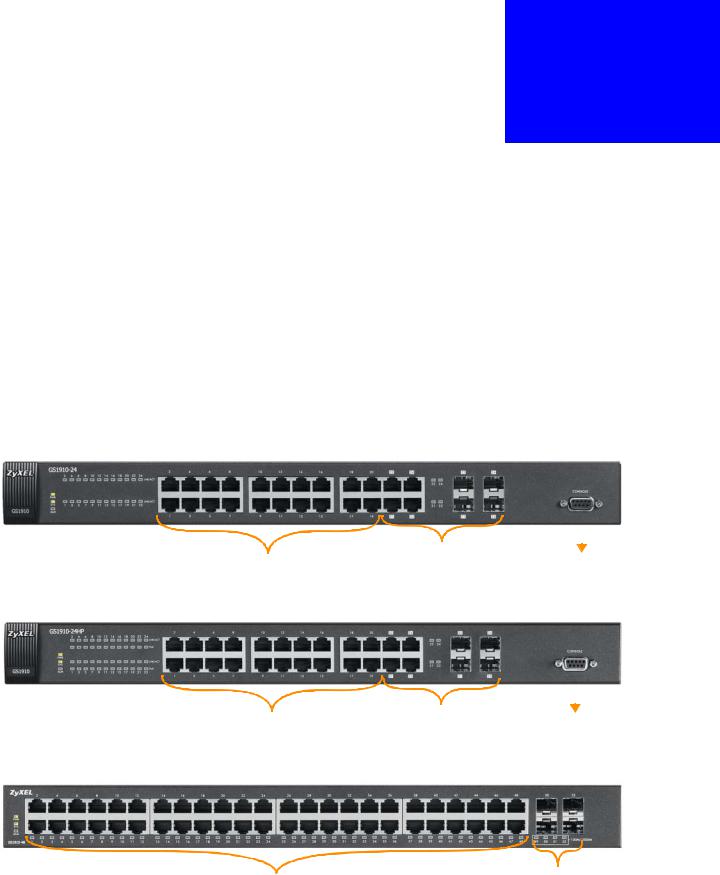
3.1 Front Panel Connections
The figure below shows the front panel of the Switch.
Figure 8 Front Panel: GS1910-24
|
10/100/1000 Mbps RJ-45 / SFP |
|
|
|
|
10/100/1000 Mbps |
Console Port |
||||
Dual Personality Interfaces |
|||||
RJ-45 Ethernet Ports |
|
|
|
|
|
Figure 9 Front Panel: GS1910-24HP
|
10/100/1000 Mbps RJ-45 PoE / |
|
|
|
|
10/100/1000 Mbps |
Console Port |
||||
SFP Dual Personality Interfaces |
|||||
RJ-45 PoE Ports |
|
|
|
||
|
|
|
|
||
Figure 10 Front Panel: GS1910-48
10/100/1000 Mbps |
SFP Slots |
|
|
RJ-45 Ethernet Ports |
|
|
15 |
GS1910/XGS1910 Series User’s Guide |
|
|
|

Chapter 3 Hardware Overview
Figure 11 Front Panel: GS1910-48HP
10/100/1000 Mbps |
SFP Slots |
|
|
RJ-45 PoE Ports |
|
Figure 12 Front Panel: XGS1910-24
SFP+ Slot
|
|
|
|
|
|
|
10/100/1000 Mbps |
10/100/1000 Mbps RJ-45 / SFP |
|
|
|
|
|
|
|
|
|
|||
|
|
|
|
|||
Dual Personality Interfaces |
Console Port |
|||||
RJ-45 Ethernet Ports |
||||||
Figure 13 Front Panel: XGS1910-48
SFP+ Slot
10/100/1000 Mbps |
|
|
|
10/100/1000 Mbps RJ-45 / SFP |
|||
RJ-45 Ethernet Ports |
Dual Personality Interfaces |
||
The following table describes the ports.
Table 1 Panel Connections
CONNECTOR DESCRIPTION
10/100/1000 Connect these ports to a computer, a hub, an Ethernet switch or router. Mbps RJ-45
Ethernet Ports
10/100/1000 Connect these ports to a computer, a hub, an Ethernet switch or router. Mbps RJ-45 PoE
Ports (GS191024HP and GS1910-48HP only)
16 |
|
|
GS1910/XGS1910 Series User’s Guide |
|
|
|
|
|
|
|
Chapter 3 Hardware Overview |
|
|
|
|
Table 1 Panel Connections (continued) |
|
|
CONNECTOR |
DESCRIPTION |
|
Dual |
Each interface has one 10/100/1000Base-T RJ-45 port and one Small |
|
Personality |
Form-Factor Pluggable (SFP) slot (also called a mini-GBIC (Gigabit |
|
Interfaces |
Interface Converter) slot), with one port active at a time. |
|
|
|
|
|
• 10/100/1000Base-T Ports or 10/100/1000Base-T PoE Ports (GS1910- |
|
|
24HP and GS1910-48HP only): |
|
|
Connect these ports to high-bandwidth backbone network Ethernet |
|
|
switches using Category 5/5e/6 1000Base-T Ethernet cables. |
|
|
Use an 8-wire Ethernet cable for Gigabit connections. Using a 4-wire |
|
|
Ethernet cable limits your connection to 100 Mbps. Note that the |
|
|
connection speed also depends on what the Ethernet device at the |
|
|
other end can support. |
|
|
|
|
|
• SFP Slots: |
|
|
Use SFP transceivers in these ports for 1000Base-X fiber-optic |
|
|
connections to backbone Ethernet switches. |
|
|
|
|
SFP Slots |
Use SFP transceivers in these slots for fiber-optic or copper connections |
|
(GS1910-48 |
to backbone Ethernet switches. |
|
and GS1910- |
|
|
48HP only) |
|
|
|
|
|
SFP+ Slots |
Use SFP+ transceivers in these slots for fiber-optic connections to |
|
(XGS1910-24 |
backbone Ethernet switches. |
|
and XGS1910- |
|
|
48 only) |
|
|
|
|
|
Console Port |
At the time of writing, this port is reserved for future use, such as |
|
|
firmware upgrade using an RS-232 cable. |
|
|
|
3.1.1 Ethernet Ports
The Switch has 1000Base-T auto-negotiating, auto-crossover Ethernet ports. In 10/100/1000 Mbps Gigabit Ethernet, the speed can be 10Mbps, 100 Mbps or 1000 Mbps. The duplex mode can be both half or full duplex at 100 Mbps and full duplex only at 1000 Mbps.
An auto-negotiating port can detect and adjust to the optimum Ethernet speed (10/100/1000 Mbps) and duplex mode (full duplex or half duplex) of the connected device.
An auto-crossover (auto-MDI/MDI-X) port automatically works with a straightthrough or crossover Ethernet cable.
3.1.1.1 Default Ethernet Settings
The factory default negotiation settings for the Ethernet ports on the Switch are:
•Speed: Auto
•Duplex: Auto
•Flow control: Off
•Dual Personality Interface: Fiber-optic module first
|
17 |
GS1910/XGS1910 Series User’s Guide |
|
|
|

Chapter 3 Hardware Overview
3.1.2 Dual Personality Interfaces
There are four dual personality interfaces, comprising four 1000Base-T/SFP combo ports. For each interface you can connect either to the 1000Base-T port or the SFP slot. If an SFP transceiver is inserted in the SFP slot, the corresponding 1000Base- T port will be disabled.
Note: Connect the 1000Base-T RJ-45 port only after the transceiver is removed from the corresponding SFP slot.
3.1.3 SFP/SFP+ Slots
These are slots for Small Form-Factor Pluggable (SFP) or SFP+ transceivers. The SFP is also referred to as a mini-GBIC. The SFP+ (SFP Plus) is an enhanced version of the SFP and supports data rates of 10 Gbps. A transceiver is a single unit that houses a transmitter and a receiver. Use a transceiver to connect a fiberoptic cable to the Switch. The Switch does not come with transceivers. You must use transceivers that comply with the Small Form-Factor Pluggable (SFP) Transceiver MultiSource Agreement (MSA). See the SFF committee’s INF-8074i specification Rev 1.0 for details.
You can change transceivers while the Switch is operating. You can use different transceivers to connect to Ethernet switches with different types of fiber-optic connectors.
•Type: SFP connection interface
•Connection speed: 1 Gigabit per second (Gbps) or 10 Gigabit per second (Gbps)
To avoid possible eye injury, do not look into an operating fiberoptic module’s connectors.
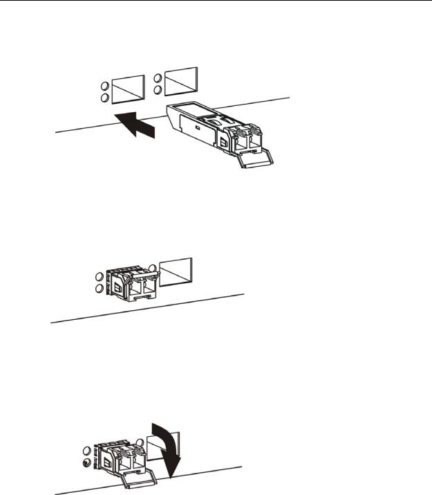
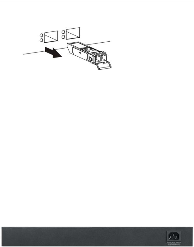
3.1.3.1 Transceiver Installation
Use the following steps to install a transceiver (SFP or SFP+ module).
18 |
|
|
GS1910/XGS1910 Series User’s Guide |
|
|
|
|
|
Chapter 3 Hardware Overview
1Insert the transceiver into the slot with the exposed section of PCB board facing down.
Figure 14 Transceiver Installation Example
2Press the transceiver firmly until it clicks into place.
3The Switch automatically detects the installed transceiver. Check the LEDs to verify that it is functioning properly.
Figure 15 Installed Transceiver
3.1.3.2 Transceiver Removal
Use the following steps to remove a transceiver (SFP or SFP+ module).
1Open the transceiver’s latch (latch styles vary).
Figure 16 Opening the Transceiver’s Latch Example
|
19 |
GS1910/XGS1910 Series User’s Guide |
|
|
|
Chapter 3 Hardware Overview
2Pull the transceiver out of the slot.
Figure 17 Transceiver Removal Example
3.1.4Console Port
For local management, you can use a computer with terminal emulation software configured to the following parameters:
•VT100 terminal emulation
•115200 bps
•No parity, 8 data bits, 1 stop bit
•No flow control
Connect the male 9-pin end of the RS-232 console cable to the console port of the Switch. Connect the female end to a serial port (COM1, COM2 or other COM port) of your computer.
3.2 Rear Panel
The following figure shows the rear panel of the Switch. The rear panel contains a connector for the power receptacle. The GS1910-48 and GS1910-48HP also have a console port on the rear panel. The XGS1910-48 has one console port and two SFP+ slots on the rear panel.
Figure 18 Rear Panel: GS1910-24
20 |
|
|
GS1910/XGS1910 Series User’s Guide |
|
|
|
|
|
Chapter 3 Hardware Overview
Figure 19 Rear Panel: GS1910-24HP
Figure 20 Front Panel: GS1910-48
Figure 21 Front Panel: GS1910-48HP
Figure 22 Front Panel: XGS1910-24
Figure 23 Front Panel: XGS1910-48
3.2.1 Power Connector
Make sure you are using the correct power source as shown on the panel and that no objects obstruct the airflow of the fans.
Use the following procedures to connect the Switch to a power source after you have installed it.
1Connect the female end of the power cord to the power socket of your Switch.
2Connect the other end of the cord to a power outlet.
Keep the power supply switch and the Switch’s power switch in the OFF position until you come to the procedure for turning on the power.
Note: Use only power wires of the required diameter for connecting the Switch to a power supply.
|
21 |
GS1910/XGS1910 Series User’s Guide |
|
|
|

Chapter 3 Hardware Overview
3.3 LEDs
The following table describes the LEDs.
Table 2 LEDs
LED |
COLOR |
STATUS |
DESCRIPTION |
|
PoE |
Green |
On |
Each Ethernet port’s LED is changed to act as a PoE LED |
|
(GS1910- |
|
|
by using the LED MODE button on the front panel. |
|
48HP |
|
|
|
|
|
Off |
Each Ethernet port’s LED is changed back to act as a |
||
only) |
|
|||
|
|
LNK/ACT LED by using the LED MODE button on the |
||
|
|
|
||
|
|
|
front panel. |
|
|
|
|
|
|
STACK |
Green |
On |
The Switch is acting as the master in stacking. |
|
(XGS191 |
|
|
|
|
Amber |
On |
The Switch is acting as the backup master device in |
||
0-24 and |
||||
|
|
stacking. |
||
XGS1910 |
|
|
||
|
|
|
||
-48 only) |
|
Blinking |
The Switch is acting as a slave member in stacking and |
|
|
|
|
is being selected by the master in its web configurator |
|
|
|
|
stack screen. |
|
|
|
|
|
|
|
|
Off |
The Switch is not working in stacking mode. |
|
|
|
|
|
|
PWR |
Green |
On |
The system is turned on. |
|
|
|
|
|
|
|
|
Off |
The system is off. |
|
|
|
|
|
|
SYS |
Green |
Blinking |
The system is rebooting and performing self-diagnostic |
|
|
|
|
tests. |
|
|
|
|
|
|
|
|
On |
The system is on and functioning properly. |
|
|
|
|
|
|
|
|
Off |
The power is off or the system is not ready/ |
|
|
|
|
malfunctioning. |
|
|
|
|
|
|
ALM |
Red |
On |
There is a hardware failure. |
|
|
|
|
|
|
|
|
Off |
The system is functioning normally. |
|
|
|
|
|
|
10/100/1000 Mbps RJ-45 Ports |
|
|||
|
|
|
|
|
LNK/ACT |
Green |
Blinking |
The system is transmitting/receiving to/from a 10/1000 |
|
|
|
|
Mbps Ethernet network. |
|
|
|
|
|
|
|
|
On |
The link to a 10/1000 Mbps Ethernet network is up. |
|
|
|
|
|
|
|
Amber |
Blinking |
The system is transmitting/receiving to/from a 100 |
|
|
|
|
Mbps Ethernet network. |
|
|
|
|
|
|
|
|
On |
The link to a 100 Mbps Ethernet network is up. |
|
|
|
|
|
|
|
|
Off |
The link to an Ethernet network is down. |
|
|
|
|
|
|
PoE |
Green |
On |
Power supplied to all PoE Ethernet ports meets the IEEE |
|
(GS1910- |
|
|
802.3at standard. |
|
24HP and |
|
|
|
|
Amber |
On |
Power supplied to all PoE Ethernet ports meets the IEEE |
||
GS1910- |
|
|
802.3af standard. |
|
48HP |
|
|
||
|
|
|
||
only) |
|
Off |
There is no power supplied. |
|
|
|
|
|
|
SFP Slots
22 |
|
|
GS1910/XGS1910 Series User’s Guide |
|
|
|
|
|

Chapter 3 Hardware Overview
Table 2 |
LEDs (continued) |
|
||
LED |
|
COLOR |
STATUS |
DESCRIPTION |
LNK/ACT |
|
Green |
Blinking |
The system is transmitting/receiving to/from a 1000 |
|
|
|
|
Mbps Ethernet network. |
|
|
|
|
|
|
|
|
On |
The link to a 1000 Mbps Ethernet network is up. |
|
|
|
|
|
|
|
Amber |
Blinking |
The system is transmitting/receiving to/from a 100 |
|
|
|
|
Mbps Ethernet network. |
|
|
|
|
|
|
|
|
On |
The link to a 100 Mbps Ethernet network is up. |
|
|
|
|
|
|
|
|
Off |
The link to an Ethernet network is down. |
|
|
|
|
|
10G SFP+ Slots |
|
|
||
|
|
|
|
|
LNK/ACT |
|
Blue |
On |
The port has a successful connection. |
|
|
|
|
|
|
|
|
Blinking |
The port is receiving or transmitting data. |
|
|
|
|
|
|
|
|
Off |
This link is disconnected. |
|
|
|
|
|
|
23 |
GS1910/XGS1910 Series User’s Guide |
|
|
|
Loading...