


Zeiss Humphrey FDT User manual
|
Eye Care Menu |
Note: Drawings and Schematics are |
|
|
not available in this revision. |
|
Operator Manual |
|
|
|
|
|
|
HUMPHREY |
|
FDT Visual Field Instrument |
|
SERVICE MANUAL
Includes CE Model
Part Number 112120 |
Copyright 1997 |
Revision B October 1997 |
Welch Allyn Inc. |

Part No |
Rev |
Description |
ECN # |
Date |
Approved |
|
|
|
|
|
|
|
|
112120 |
A |
New Release of FDT Service Manual |
5-36180 |
8/22/97 |
RJS |
|
|
|
|
|
|
|
|
112120 |
B |
Added CE version Section 9 , Calibration |
5-36574 |
10/21/97 |
RJS |
|
Limits and Error Messages. |
||||||
|
|
|
|
|
||
|
|
|
|
|
|
DRAWINGS AND / OR ILLUSTRATIONS AND / OR PART NUMBERS CONTAINED IN THIS DOCUMENT ARE FOR REFERENCE PURPOSES ONLY! FOR CURRENT REVISIONS CALL HUMPHREY INSTRUMENTS CUSTOMER SERVICE
ii HUMPHREY FDT VISUAL FIELD INSTRUMENT |
SERVICE MANUAL 112120 REV. B |

Contents
Section 1: General Information |
|
|
|
|
|
|
||||||||||||||||||||||||||||||||||||||||||||||||||||||||||||||||||||||||||||||||||||||||||||||||||||||||||||||||||||||||||||||||||||||||||||||||||||||||||
About The 710 Series and the CE Model |
|
|
|
|
|
|
|
|
|
|
|
|
|
|
|
|
|
|
|
|
|
|
|
|
|
|
|
|
|
|
|
|
|
|
|
|
|
|
|
|
|
|
|
|
|
|
|
|
|
|
|
|
|
|
|
|
|
|
|
|
|
|
|
|
|
|
|
|
|
|
|
|
|
|
|
|
|
|
|
|
|
|
|
|
|
|
|
|
|
|
|
|
|
|
|
|
|
|
|
|
|
|
|
|
|
|
|
|
|
|
|
|
|
|
|
|
|
|
|
|
|
|
|
|
|
|
|
|
|
|
|
|
|
|
|
|
|
|
|
|
|
|
|
|
|
|
|
|
|
1 |
||||||||||
|
|
|
|
|
|
|
|
|
|
|
|
|
|
|
|
|
|
|
|
|
|
|
|
|
|
|
|
|
|
|
|
|
|
|
|
|
|
|
|
|
|
|
|
|
|
|
|
|
|
|
|
|
|
|
|
|
|
|
|
|
|
|
|
|
|
|
|
|
|
|
|
|
|
|
|
|
|
|
|
|
|
|
|
|
|
|
|
|
|
|
|
|
|
|
|
|
|
|
|
|
|
|
|
|
|
|
|
|
||||||||||||||||||||||||||||||||||||||||||||||||||||
Help Information CUSTOMER SERVICE PHONE NUMBER |
|
|
|
|
|
|
|
|
|
|
|
|
|
|
|
|
|
|
|
|
|
|
2 |
|||||||||||||||||||||||||||||||||||||||||||||||||||||||||||||||||||||||||||||||||||||||||||||||||||||||||||||||||||||||||||||||||||||||||
|
|
|
|
|
|
|
|
|
|
|
|
|||||||||||||||||||||||||||||||||||||||||||||||||||||||||||||||||||||||||||||||||||||||||||||||||||||||||||||||||||||||||||||||||||||||||||||||||||||
Important Safety Warnings and Service Notes |
|
|
|
|
|
|
|
|
|
|
|
|
|
|
|
|
|
|
|
|
|
|
|
|
|
|
|
|
|
|
|
|
|
|
|
|
|
|
|
|
|
|
|
|
|
|
|
|
|
3 |
||||||||||||||||||||||||||||||||||||||||||||||||||||||||||||||||||||||||||||||||||||||||||||||||||||||||||||||
Main Menu Architecture Ver.2.10 |
|
|
|
|
|
|
|
|
|
|
|
|
|
|
|
|
|
|
|
|
|
|
|
|
|
|
|
|
|
|
|
|
|
|
|
|
|
|
|
|
|
|
|
|
|
|
|
|
|
|
|
|
|
|
|
|
|
|
|
|
|
|
|
|
|
|
|
|
|
|
|
|
|
|
|
|
|
|
|
|
|
|
|
|
|
|
|
|
|
|
|
|
|
|
|
|
|
|
|
|
|
|
|
|
|
|
|
|
|
|
|
|
|
|
|
|
|
|
|
|
|
|
|
|
|
|
|
|
|
|
|
|
|
|
|
|
|
|
|
|
|
|
|
|
|
|
|
|
|
|
|
|
5 |
|||||||
|
|
|
|
|
|
|
|
|
|
|
|
|
|
|
|
|
|
|
|
|
|
|
|
|
|
|
|
|
|
|
|
|
|
|
|
|
|
|
|
|
|
|
|
|
|
|
|
|
|
|
|
|
|
|
|
|
|
|
|
|
|
|
|
|
|
|
|
|
|
|
|
|
|
|
|
|
|
|
|
|
|
|
|
|
|
|||||||||||||||||||||||||||||||||||||||||||||||||||||||||||||||||||||||||||
Hardware System Wiring Block Diagram |
|
|
|
|
|
|
|
|
|
|
|
|
|
|
|
|
|
|
|
|
|
|
|
|
|
|
|
|
|
|
|
|
|
|
|
|
|
|
|
|
|
|
|
|
|
|
|
|
|
|
|
|
|
|
|
|
|
|
|
|
|
|
|
|
|
|
|
|
|
|
|
|
|
|
|
|
|
|
|
|
|
|
|
|
|
|
|
|
|
|
|
|
|
|
|
|
|
|
|
|
|
|
|
|
|
|
|
|
|
|
|
6 |
||||||||||||||||||||||||||||||||||||||||||||||||
|
|
|
|
|
|
|
|
|
|
|
|
|
|
|
|
|
|
|
|
|
|
|
|
|
|
|
|
|
|
|
|
|
|
|
|
|
|
|
|
|
|
|
|
|
|
|
|
|
|
|
|
|
|
|
|
|
|
|
|
|
|
|
|
|
|
|
|
|
|
|
|
|
|
|
|
|
|
|
||||||||||||||||||||||||||||||||||||||||||||||||||||||||||||||||||||||||||||||||||
System Function Electrical Architecture Block Diagram |
|
|
|
|
|
|
|
|
|
|
|
|
|
|
|
|
|
|
|
|
|
|
|
|
|
|
|
|
|
|
|
|
|
|
|
|
|
|
|
|
|
|
|
|
|
|
|
|
|
|
|
|
|
|
|
|
|
|
|
|
|
|
|
|
|
|
|
|
|
|
7 |
|||||||||||||||||||||||||||||||||||||||||||||||||||||||||||||||||||||||||||||||||||||||||
|
|
|
|
|
|
|
|
|
|
|
|
|
|
|
|
|
|
|
|
|
|
|
|
|
|
|
|
|
|
|
|
|
|
|
|
|
|
|
|
|
|
|
|
|
|
|
|
|
|
|
||||||||||||||||||||||||||||||||||||||||||||||||||||||||||||||||||||||||||||||||||||||||||||||||||||||||||||||
Section 2: |
Service |
|
|
|
|
|
|
|
|
|
|
|
|
|
|
|
|
|
|
|
|
|
|
|||||||||||||||||||||||||||||||||||||||||||||||||||||||||||||||||||||||||||||||||||||||||||||||||||||||||||||||||||||||||||||||||||||||||||||||||||||||||||||||||||||||||||||||||||||||||||||||||||||||||||
Incoming Inspection |
|
|
|
|
|
|
|
|
|
|
|
|
|
|
|
|
|
|
|
|
|
|
|
|
|
|
|
|
|
|
|
|
|
|
|
|
|
|
|
|
|
|
|
|
|
|
|
|
|
|
|
|
|
|
|
|
|
|
|
|
|
|
|
|
|
|
|
|
|
|
|
|
|
|
|
|
|
|
|
|
|
|
|
|
|
|
|
|
|
|
|
|
|
|
|
|
|
|
|
|
|
|
|
|
|
|
|
|
|
|
|
|
|
|
|
|
|
|
|
|
|
|
|
|
|
|
|
|
|
|
|
|
|
|
|
|
|
|
|
|
|
|
|
|
|
|
|
|
|
|
|
|
|
|
|
|
|
|
|
|
|
|
|
|
|
|
|
|
|
|
|
|
|
|
|
|
|
|
|
|
|
|
|
|
|
|
|
|
|
|
|
|
|
|
|
|
|
|
|
|
|
|
|
|
|
|
|
|
|
|
|
|
|
|
|
1 |
||||||||||
|
|
|
|
|
|
|
|
|
|
|
|
|
|
|
|
|
|
|
|
|
|
|
|
|
|
|
|
|
|
|
|
|
|
|
|
|
|
|
|
|
|
|
|
|
|
|
|
|
|
|
|
|
|
|
|
|
|
|
|
|
|
|
|
|
|
|
|
|
|
|
|
|
|
|
|
|
|
|
|
|
|
|
|
|
|
|
|
|
|
|
|
|
|
|
|
|
|
|
|
|
|
|
|
|
|
|
|
|
|
|
|
|
|
|
|
|
|
|
|
|
|
|
|
|
|
|
|
|
|
|
|
|
|
|
|
|
|
|
|
|
|
|
|
|
|
|
|
|
|
|
|
|
||||||||||||||||||||||||||||||||||||||||||||||||||||||||||||||||||||||||||
Tools Required for Service and Factory Calibration and Software Uploading |
|
|
|
|
2 |
|||||||||||||||||||||||||||||||||||||||||||||||||||||||||||||||||||||||||||||||||||||||||||||||||||||||||||||||||||||||||||||||||||||||||||||||||||||||||||||||||||||||||||||||||||||||||||||||||||||||||||||||||||||||||||||
|
|
|
|
|
|
|
|
|
|
|
|
|
|
|
|
|
|
|
|
|
|
|
|
|
|
|
|
|
|
|
|
|
|
|
|
|
|
|
|
|
|
|
|
|
|
|
|
|
|
|
|
|
|
|
|
|
|
|
|
|
|
|
|
|
|
|
|
|
|
|
|
|
|
|
|
|
|
|
|
|
|
|
|
|
|
|
|
|
|
|
|
|
|
|
|
|
|
|
|
|
|
|
|
|
|
|
|
|
|
|
|
|
|
|
|
|
|
|
|
|
|
|
|
|
|
|
|
|
|
|
|
|
|
|
|
|
|
|
|
|
|
|
|
|
|
|
|
|
|
|
|
|
|
|
|
|
|
|
|
|
|
|
|
|
|
|
|
|
|
|
|
|
|
|
|
|
|
|
|
|
|
|
|
|
|
|
|
|
|
|
|
|
|
|
|
|
|
|
|
|
|
|
|
|
|
|
|
|
|
|
|
|
|
|
|
|
|
|
|
|
|
|
|
|
|
|
Factory Calibration for Software Version 1.20 or Higher |
|
|
|
|
|
|
|
|
|
|
|
|
|
|
|
|
|
|
|
|
|
|
|
|
|
|
|
|
|
|
|
|
|
|
|
|
|
|
|
|
|
|
|
|
|
|
|
|
|
|
|
|
|
|
|
|
|
|
|
|
|
|
|
|
|
|
|
|
|
|
|
|
|
|
|
|
|
|
|
|
3 |
|||||||||||||||||||||||||||||||||||||||||||||||||||||||||||||||||||||||||||||||||||||||||||||||||||||||||||||||||||||||||||||||||||||||||||||||||
|
|
|
|
|
|
|
|
|
|
|
|
|
|
|
|
|
|
|
|
|
|
|
|
|
|
|
|
|
|
|
|
|
|
|
|
|
|
|
|
|
|
|
|
|
|
|
|
|
|
|
||||||||||||||||||||||||||||||||||||||||||||||||||||||||||||||||||||||||||||||||||||||||||||||||||||||||||||||||||||||||||||||||||||||||||||||||||||||||||||||||||||||||||||||||
Loading Software for FDT |
5 |
|||||||||||||||||||||||||||||||||||||||||||||||||||||||||||||||||||||||||||||||||||||||||||||||||||||||||||||||||||||||||||||||||||||||||||||||||||||||||||||||||||||||||||||||||||||||||||||||||||||||||||||||||||||||||||||||||
Final Testing |
|
|
|
|
|
|
|
|
|
|
|
|
|
|
|
|
|
|
|
|
|
|
|
|
|
|
|
|
|
|
|
|
|
|
|
|
|
|
|
|
|
|
|
|
|
|
|
|
|
|
|
|
|
|
|
|
|
|
|
|
|
|
|
|
|
|
|
|
|
|
|
|
|
|
|
|
|
|
|
|
|
|
|
|
|
|
|
|
|
|
|
|
|
|
|
|
|
|
|
|
|
|
|
|
|
|
|
|
|
|
|
|
|
|
|
|
|
|
|
|
|
|
|
|
|
|
|
|
|
|
|
|
|
|
|
|
|
|
|
|
|
|
|
|
|
|
|
|
|
|
|
|
|
|
|
|
|
|
|
|
|
|
|
|
|
|
|
|
|
|
|
|
|
|
|
|
|
|
|
|
|
|
|
|
|
|
|
6 |
||||||||||||||||||||||||||||||||||||||
Hypot Ground Continuity, and Leakage Current Testing |
|
|
|
|
|
|
|
|
|
|
|
|
|
|
|
|
|
|
|
|
|
11 |
||||||||||||||||||||||||||||||||||||||||||||||||||||||||||||||||||||||||||||||||||||||||||||||||||||||||||||||||||||||||||||||||||||||||||||||||||||||||||||||||||||||||||||||||||||||||||||||||||||||||||||
Important Shipping Information |
|
|
|
|
|
|
|
|
|
|
|
|
|
|
|
|
|
|
|
|
|
|
|
|
|
|
|
|
|
|
|
|
|
|
|
|
|
|
|
|
|
|
|
|
|
|
|
|
|
|
|
12 |
||||||||||||||||||||||||||||||||||||||||||||||||||||||||||||||||||||||||||||||||||||||||||||||||||||||||||||||||||||||||||||||||||||||||||||||||||||||||||||||||||||||||||||||
|
|
|
|
|
|
|
|
|
|
|
|
|
|
|
|
|
|
|
|
|
|
|
|
|
|
|
|
|
|
|||||||||||||||||||||||||||||||||||||||||||||||||||||||||||||||||||||||||||||||||||||||||||||||||||||||||||||||||||||||||||||||||||||||||||||||||||||||||||||||||||||||||||||||||||||||||||||||||||||
Calibration |
Limits Information |
|
|
|
|
|
|
|
|
|
|
|
|
|
|
|
|
|
|
|
|
|
|
|
|
|
|
|
|
|
|
|
|
|
|
|
|
|
|
|
|
|
|
13 |
||||||||||||||||||||||||||||||||||||||||||||||||||||||||||||||||||||||||||||||||||||||||||||||||||||||||||||||||||||||||||||||||||||||||||||||||||||||||||||||||||||||||||||||||||||||
|
|
|
|
|
|
|
|
|
|
|
|
|
|
|
|
|
|
|
|
|
|
|
||||||||||||||||||||||||||||||||||||||||||||||||||||||||||||||||||||||||||||||||||||||||||||||||||||||||||||||||||||||||||||||||||||||||||||||||||||||||||||||||||||||||||||||||||||||||||||||||||||||||||||
Product Updates |
|
|
|
|
|
|
|
|
|
|
|
|
|
|
|
|
|
|
|
|
|
|
|
|
|
|
|
|
|
|
|
|
|
|
|
|
|
|
|
|
|
|
|
|
|
|
|
|
|
|
|
|
|
|
15 |
|||||||||||||||||||||||||||||||||||||||||||||||||||||||||||||||||||||||||||||||||||||||||||||||||||||||||||||||||||||||||||||||||||||||||||||||||||||||||||||||||||||||||||
Section 3: Troubleshooting |
|
|
|
|
|
|
|
|
|
|
|
|
|
|
|
|
|
|
|
|
|
|
|
|
|
|
|
|
|
|
|
|
|
|
|
|
|
|
|
|
|
|
|
|
|
|
|
|
|
|
|
|
|
|
|
|
|
|
|
|
|
|
|
|
|
|
|
|
|
|
|
|
|
|
|
|
|
|
|
|
|
|
|
|
|
|
|
|
|
|
|
|
||||||||||||||||||||||||||||||||||||||||||||||||||||||||||||||||||||||||||||||||||||||||||||||||||||||||||||||||||||||||||||||||||||||||||||||||||||||||||||||||||||||||||||||||||||||||||||||||||||||||
Chief Complaint, Cause, Corrective Action |
|
|
|
|
|
|
|
|
|
|
|
|
|
|
|
|
|
|
|
|
|
|
|
|
|
|
|
|
|
|
|
|
|
|
|
|
|
1 |
||||||||||||||||||||||||||||||||||||||||||||||||||||||||||||||||||||||||||||||||||||||||||||||||||||||||||||||||||||||||||||||||||||||||||||||||||||||||||||||||||||||||||||||||||||||||||||||||||||||||||||||||||||||||||||||||||||||||||||||||||||||||||||||
Power On Self Test |
|
(P.O.S.T.) Status Table |
3 |
|||||||||||||||||||||||||||||||||||||||||||||||||||||||||||||||||||||||||||||||||||||||||||||||||||||||||||||||||||||||||||||||||||||||||||||||||||||||||||||||||||||||||||||||||||||||||||||||||||||||||||||||||||||||||||||||||||||||||||||||||||||||||||||||||||||||||||||||||||||||||||||||||
FDT Terminology |
|
|
|
|
|
|
|
|
|
|
|
|
|
|
|
|
|
|
|
|
|
|
|
|
|
|
|
|
|
|
|
|
|
|
|
|
|
|
|
|
|
|
|
|
|
|
|
|
|
|
|
|
|
|
|
|
|
|
|
|
|
|
|
|
|
|
|
|
|
|
|
|
|
|
|
|
|
|
|
|
|
|
|
|
|
|
|
|
|
|
|
|
|
|
|
|
|
|
|
|
|
|
|
|
|
|
|
|
|
|
|
|
|
|
|
|
|
|
|
|
|
|
|
|
|
|
|
|
|
|
|
|
|
|
|
|
|
|
|
|
|
|
|
|
|
|
|
|
|
|
|
|
|
|
|
|
|
|
|
|
|
|
|
|
|
|
|
|
|
|
|
|
|
|
|
|
|
|
|
|
|
|
|
|
|
|
|
|
|
|
|
|
|
|
|
|
|
|
|
|
|
|
|
|
|
|
|
|
|
|
|
|
|
|
|
|
|
|
|
|
|
|
|
|
|
|
|
|
|
|
|
|
|
|
|
|
|
|
|
|
|
|
|
|
|
|
|
|
|
|
|
|
|
|
|
|
|
|
|
|
|
|
|
|
|
|
|
|
|
|
|
|
|
|
|
|
|
|
|
|
|
|
4 |
|||||||||
FDT Error Messages |
|
|
|
|
|
|
|
|
|
|
|
|
|
|
|
|
|
|
|
|
|
|
|
|
|
|
|
|
|
|
|
|
|
|
|
|
|
|
|
|
|
|
|
|
|
|
|
|
|
|
|
|
|
|
|
5 |
||||||||||||||||||||||||||||||||||||||||||||||||||||||||||||||||||||||||||||||||||||||||||||||||||||||||||||||||||||||||||||||||||||||||||||||||||||||||||||||||||||||||||||||||||||||||||||||||||||||||||||||||||||||||||||||||||||||||||||
Section 4: Disassembly and Repair |
|
|
|
|
|
|
|
|
|
|
|
|
|
|
|
|
|
|
|
|
|
|
|
|
|
|
|
|
|
|
|
|
|
|
|
|
|
|
|
|
|
|
|
|
|
|
|
|
|
|
|
|
|
|
|
|
|
|
|
|
|
|
|
|
|
|
|
|
|
|
|
|
|
|
|
|
|
|
|
|
|
|
|
|
|
|
|
|
|
|
|
|
||||||||||||||||||||||||||||||||||||||||||||||||||||||||||||||||||||||||||||||||||||||||||||||||||||||||||||||||||||||||||||||||||||||||||||||||||||||||||||||||||||||||||||||||||||||||||||||||||||||||
4.1 |
|
Removal of Rear Housing/LCD Assembly |
|
|
|
|
|
|
|
|
|
|
|
|
|
|
|
|
|
|
|
|
|
|
|
|
|
|
|
|
|
|
|
|
|
|
|
|
|
|
|
|
|
|
|
|
|
|
|
|
|
|
|
|
|
|
|
|
|
|
|
|
|
|
|
|
|
|
|
|
|
|
|
|
|
|
|
|
|
|
|
|
|
|
|
|
|
|
|
|
|
|
|
|
|
|
|
|
|
|
|
|
|
|
|
|
|
|
|
|
|
|
|
|
|
|
|
|
|
|
|
1 |
||||||||||||||||||||||||||||||||||||||||||||||||||||||||||||||||||||||||||||||||||||||||||||||||||||||||||||||||||||||||||||||||||||||||||||||||||||||||||||||||||||||||||
4.2 |
|
Replacement of Rear Housing/LCD Assembly |
|
|
|
|
|
|
|
|
|
|
|
|
|
|
|
|
|
|
|
|
|
|
|
|
|
|
|
|
|
|
|
|
|
|
|
|
|
|
|
|
|
|
|
|
|
|
|
|
|
|
|
|
|
|
|
|
|
|
|
|
|
|
|
|
|
|
|
|
|
|
|
|
|
|
|
|
|
|
|
|
|
|
|
|
|
|
|
|
|
|
|
|
|
3 |
||||||||||||||||||||||||||||||||||||||||||||||||||||||||||||||||||||||||||||||||||||||||||||||||||||||||||||||||||||||||||||||||||||||||||||||||||||||||||||||||||||||||||||||||||||||||||||||||||||
|
|
|
|
|
|
|
|
|
|
|
|
|
|
|
|
|
|
|
|
|
|
|
|
|
|
|
|
|
|
|
|
|
|
|
|
|
|
|
|
|
|
|
|
|
|
|
|
|
|
|
|
|
|
|
|
|
|
|
|
|
|
|
|
|
|
|
|
|
||||||||||||||||||||||||||||||||||||||||||||||||||||||||||||||||||||||||||||||||||||||||||||||||||||||||||||||||||||||||||||||||||||||||||||||||||||||||||||||||||||||||||||||||||||||||||||||||||||||||||||||||||||||||||||||||
4.3 |
|
Disassembly of Optics |
|
|
|
|
|
|
|
|
|
|
|
|
|
|
|
|
|
|
|
|
|
|
|
|
|
|
|
|
|
|
|
|
|
|
|
|
|
|
3 |
|||||||||||||||||||||||||||||||||||||||||||||||||||||||||||||||||||||||||||||||||||||||||||||||||||||||||||||||||||||||||||||||||||||||||||||||||||||||||||||||||||||||||||||||||||||||||||||||||||||||||||||||||||||||||||||||||||||||||||||||||||||||||||
4.4 |
|
Assembly of Optics |
|
|
|
|
|
|
|
|
|
|
|
|
|
|
|
|
|
|
|
|
|
|
|
|
|
|
|
|
|
|
|
|
|
|
|
|
|
|
|
|
|
|
|
|
|
|
|
|
|
|
|
|
|
|
|
|
|
|
|
|
|
|
|
|
|
|
|
|
|
|
|
|
|
|
|
|
|
|
|
|
|
|
|
|
|
|
|
|
|
|
|
|
|
|
|
|
|
|
|
|
|
|
|
|
|
|
|
|
|
|
|
|
11 |
|||||||||||||||||||||||||||||||||||||||||||||||||||||||||||||||||||||||||||||||||||||||||||||||||||||||||||||||||||||||||||||||||||||||||||||||||||||||||||||||||||||||||||||||||
4.5 |
|
Removal of Printer |
|
|
|
|
|
|
|
|
|
|
|
|
|
|
|
|
|
|
|
|
|
|
|
|
|
|
|
|
|
|
|
|
|
|
|
|
|
|
|
|
|
|
|
|
|
|
|
|
|
|
|
|
|
|
|
|
|
|
|
|
|
|
|
|
|
|
|
|
|
|
|
|
|
|
|
|
|
|
|
|
|
|
|
|
|
|
|
|
|
|
|
|
|
|
|
|
|
|
|
|
|
|
|
|
|
|
|
|
|
|
|
|
|
|
|
|
|
|
|
|
|
|
|
|
|
|
|
|
|
|
|
|
|
|
|
|
|
|
|
|
|
|
|
|
|
|
|
|
|
|
|
|
|
|
|
|
|
|
|
|
|
|
|
|
|
|
|
|
|
|
|
|
|
|
|
|
|
|
|
|
|
|
|
|
|
|
|
|
|
|
|
|
|
|
|
|
|
|
|
|
|
|
|
|
|
|
|
|
|
|
|
|
|
|
|
|
|
|
|
|
|
|
|
|
|
|
|
|
|
|
|
|
|
|
|
|
|
|
|
|
15 |
|||||||||||||||||||||||||||||||||||||||||||||||||
4.6 |
|
Installing Printer |
|
|
|
|
|
|
|
|
|
|
|
|
|
|
|
|
|
|
|
|
|
|
|
|
|
|
|
|
|
|
|
|
|
|
|
|
|
|
|
|
|
|
|
|
|
|
|
|
|
|
|
|
|
|
|
|
|
|
|
|
|
|
|
|
|
|
|
|
|
|
|
|
|
|
|
|
|
|
|
|
|
|
|
|
|
|
|
|
|
|
|
|
|
|
|
|
|
|
|
|
|
|
|
|
|
|
|
|
|
|
|
|
|
|
16 |
|||||||||||||||||||||||||||||||||||||||||||||||||||||||||||||||||||||||||||||||||||||||||||||||||||||||||||||||||||||||||||||||||||||||||||||||||||||||||||||||||||||||||||||||
|
|
|
|
|
|
|
|
|
|
|
|
|
|
|
|
|
|
|
|
|
|
|
|
|
|
|
|
|
|
|
|
|
|
|
|
|
|
|
|
|
|
|
|
|
|
|
|
|
|
|
|
|
|
|
|
|
|
|
|
|
|
|
|
|
|
|
|
|
|
|
|
|
|
|
|
|
|
|
|
|
||||||||||||||||||||||||||||||||||||||||||||||||||||||||||||||||||||||||||||||||||||||||||||||||||||||||||||||||||||||||||||||||||||||||||||||||||||||||||||||||||||||||||||||||||||||||||||||||||||||||||||||||||||
4.7 |
|
Removal of MCU/ PCB |
|
|
|
|
|
|
|
|
|
|
|
|
|
|
|
|
|
|
|
|
|
|
|
|
|
|
|
|
|
|
|
|
|
|
|
|
|
|
|
|
|
|
|
|
|
|
|
|
|
|
|
|
|
|
|
|
|
|
|
|
|
|
|
|
|
|
|
|
|
|
|
|
|
|
|
|
|
|
|
|
|
|
|
|
|
|
|
|
|
|
|
|
|
|
|
|
|
|
|
|
|
|
|
|
|
|
|
|
|
|
|
|
|
|
|
|
|
|
|
|
|
|
|
|
|
|
|
|
|
|
|
|
|
|
|
|
17 |
|||||||||||||||||||||||||||||||||||||||||||||||||||||||||||||||||||||||||||||||||||||||||||||||||||||||||||||||||||||||||||||||||||||||||||||||||||||||||
4.8 |
|
Installing MCU/PCB |
|
|
|
|
|
|
|
|
|
|
|
|
|
|
|
|
|
|
|
|
|
|
|
|
|
|
|
|
|
|
|
|
|
|
|
|
|
|
19 |
|||||||||||||||||||||||||||||||||||||||||||||||||||||||||||||||||||||||||||||||||||||||||||||||||||||||||||||||||||||||||||||||||||||||||||||||||||||||||||||||||||||||||||||||||||||||||||||||||||||||||||||||||||||||||||||||||||||||||||||||||||||||||||
4.9 |
|
Installing a Replacement Chassis/Monitor Assembly |
|
|
|
|
|
|
|
|
|
|
|
|
|
|
|
|
|
|
|
|
|
|
20 |
|||||||||||||||||||||||||||||||||||||||||||||||||||||||||||||||||||||||||||||||||||||||||||||||||||||||||||||||||||||||||||||||||||||||||||||||||||||||||||||||||||||||||||||||||||||||||||||||||||||||||||||||||||||||||||||||||||||||||||||||||||||||||||||||||||||||||||
4.10 |
|
Removal of Transformer |
|
|
|
|
|
|
|
|
|
|
|
|
|
|
|
|
|
|
|
|
|
|
|
|
|
|
|
|
|
|
|
|
|
|
|
|
|
|
|
|
|
|
|
|
|
|
|
|
|
|
|
|
|
|
|
|
|
|
|
|
|
|
|
|
|
|
|
|
|
|
|
|
|
|
|
|
|
|
|
|
|
|
|
|
|
|
|
|
|
|
|
|
|
|
|
|
|
|
|
|
|
|
|
|
|
|
|
|
|
|
|
|
|
|
|
|
|
|
|
|
|
|
|
|
|
|
|
|
|
|
|
|
|
|
|
|
|
|
|
|
|
|
|
|
|
|
|
|
|
|
|
|
|
|
|
|
|
|
|
|
|
|
|
|
|
|
|
|
|
|
|
|
|
|
|
|
|
|
|
|
|
|
|
|
|
|
|
|
|
|
|
|
|
|
|
|
|
|
|
|
|
|
|
|
|
|
20 |
|||||||||||||||||||||||||||||||||||||||||||||||||||||||||||||||||||||||||||||||||||
4.11 |
|
Installing Transformer |
|
|
|
|
|
|
|
|
|
|
|
|
|
|
|
|
|
|
|
|
|
|
|
|
|
|
|
|
|
|
|
|
|
|
|
|
|
|
|
|
|
|
|
|
|
|
|
|
|
|
|
|
|
|
|
|
|
|
|
|
|
|
|
|
|
|
|
|
|
|
|
|
|
|
|
|
|
|
21 |
|||||||||||||||||||||||||||||||||||||||||||||||||||||||||||||||||||||||||||||||||||||||||||||||||||||||||||||||||||||||||||||||||||||||||||||||||||||||||||||||||||||||||||||||||||||||||||||||||||||||||||||||||||
4.12 |
|
Removal of PRB Jack |
|
|
|
|
|
|
|
|
|
|
|
|
|
|
|
|
|
|
|
|
|
|
|
|
|
|
|
|
|
|
|
|
|
|
|
|
|
|
|
|
|
|
|
|
|
|
|
|
|
|
|
|
|
|
|
|
|
|
|
|
|
|
|
|
|
|
|
|
|
|
|
|
|
|
|
|
|
|
|
21 |
||||||||||||||||||||||||||||||||||||||||||||||||||||||||||||||||||||||||||||||||||||||||||||||||||||||||||||||||||||||||||||||||||||||||||||||||||||||||||||||||||||||||||||||||||||||||||||||||||||||||||||||||||
4.13 |
|
Replacement of PRB Jack |
|
|
|
|
|
|
|
|
|
|
|
|
|
|
|
|
|
|
|
|
|
|
|
|
|
|
|
|
|
|
|
|
|
|
|
|
|
|
|
|
|
|
|
|
|
|
|
|
|
|
|
|
21 |
|||||||||||||||||||||||||||||||||||||||||||||||||||||||||||||||||||||||||||||||||||||||||||||||||||||||||||||||||||||||||||||||||||||||||||||||||||||||||||||||||||||||||||||||||||||||||||||||||||||||||||||||||||||||||||||||||||||||||||||
4.14 |
|
Removal of Power Entry Module |
|
|
|
|
|
|
|
|
|
|
|
|
|
|
|
|
|
|
|
|
|
|
|
|
|
|
|
|
|
|
|
|
|
|
|
|
|
|
|
|
|
|
21 |
|||||||||||||||||||||||||||||||||||||||||||||||||||||||||||||||||||||||||||||||||||||||||||||||||||||||||||||||||||||||||||||||||||||||||||||||||||||||||||||||||||||||||||||||||||||||||||||||||||||||||||||||||||||||||||||||||||||||||||||||||||||||
|
|
|
|
|
|
|
|
|
|
|
|
|
|
|
|
|
|
|
|
|
|
|
|
|
|
|||||||||||||||||||||||||||||||||||||||||||||||||||||||||||||||||||||||||||||||||||||||||||||||||||||||||||||||||||||||||||||||||||||||||||||||||||||||||||||||||||||||||||||||||||||||||||||||||||||||||||||||||||||||||||||||||||||||||||||||||||||||||||||||||||||||||||
4.15 |
|
Replacement of Power Entry Module |
|
|
|
|
|
|
|
|
|
|
|
|
|
|
|
|
|
|
|
|
|
|
|
|
|
|
|
|
|
|
|
|
|
|
|
|
|
|
|
|
|
|
|
|
|
|
|
22 |
||||||||||||||||||||||||||||||||||||||||||||||||||||||||||||||||||||||||||||||||||||||||||||||||||||||||||||||||||||||||||||||||||||||||||||||||||||||||||||||||||||||||||||||||||||||||||||||||||||||||||||||||||||||||||||||||||||||||||||||||||
4.16 |
|
Removal of Visor Position Sensor (VPS) |
|
|
|
|
|
|
|
|
|
|
|
|
|
|
|
|
|
|
|
|
|
|
|
|
|
|
|
|
|
|
|
|
|
|
22 |
|||||||||||||||||||||||||||||||||||||||||||||||||||||||||||||||||||||||||||||||||||||||||||||||||||||||||||||||||||||||||||||||||||||||||||||||||||||||||||||||||||||||||||||||||||||||||||||||||||||||||||||||||||||||||||||||||||||||||||||||||||||||||||||||
4.17 |
|
Replacement of VPS |
|
|
|
|
|
|
|
|
|
|
|
|
|
|
|
|
|
|
|
|
|
|
|
|
|
|
|
|
|
|
|
|
|
|
|
|
|
|
|
|
|
|
|
|
|
|
|
|
|
|
|
|
|
|
|
|
22 |
|||||||||||||||||||||||||||||||||||||||||||||||||||||||||||||||||||||||||||||||||||||||||||||||||||||||||||||||||||||||||||||||||||||||||||||||||||||||||||||||||||||||||||||||||||||||||||||||||||||||||||||||||||||||||||||||||||||||||
|
|
|
|
|
|
|
|
|
|
|
|
|
|
|
|
|
|
|
|
|
|
|
|
|
|
|
|
|
|
|
|
|
|
|
|
|||||||||||||||||||||||||||||||||||||||||||||||||||||||||||||||||||||||||||||||||||||||||||||||||||||||||||||||||||||||||||||||||||||||||||||||||||||||||||||||||||||||||||||||||||||||||||||||||||||||||||||||||||||||||||||||||||||||||||||||||||||||||||||||||
4.18 |
|
Removal of Internal Photodetector (IP) |
|
|
|
|
|
|
|
|
|
|
|
|
|
|
|
|
|
|
|
|
|
23 |
||||||||||||||||||||||||||||||||||||||||||||||||||||||||||||||||||||||||||||||||||||||||||||||||||||||||||||||||||||||||||||||||||||||||||||||||||||||||||||||||||||||||||||||||||||||||||||||||||||||||||||||||||||||||||||||||||||||||||||||||||||||||||||||||||||||||||||
4.19 |
|
Replacement of IP / PCB |
|
|
|
|
|
|
|
|
|
|
|
|
|
|
|
|
|
|
|
|
|
|
|
|
|
|
|
|
|
|
|
|
|
|
23 |
|||||||||||||||||||||||||||||||||||||||||||||||||||||||||||||||||||||||||||||||||||||||||||||||||||||||||||||||||||||||||||||||||||||||||||||||||||||||||||||||||||||||||||||||||||||||||||||||||||||||||||||||||||||||||||||||||||||||||||||||||||||||||||||||
4.20 |
|
Removal of LCD Module/Keypad |
|
|
|
|
|
|
|
|
|
|
|
|
|
|
|
|
|
|
|
|
|
|
|
|
|
|
|
|
|
|
|
|
|
|
|
|
|
23 |
||||||||||||||||||||||||||||||||||||||||||||||||||||||||||||||||||||||||||||||||||||||||||||||||||||||||||||||||||||||||||||||||||||||||||||||||||||||||||||||||||||||||||||||||||||||||||||||||||||||||||||||||||||||||||||||||||||||||||||||||||||||||||||
SERVICE MANUAL 112120 REV. B |
HUMPHREY FDT VISUAL FIELD INSTRUMENT iii |

Section 4: Disassembly and Repair ContÕd |
|
|
|
|
|
|
|
|
|
|
|
|
|
|
|
|
|
|
|
|
|
|
|
|
|
|
|
|
|
|
|
|
|
|
|
|
|
|
|
|
|
|
|
|
|
|
|
|
|
|
|
|
|
|
|
|
|
|
|
|
|
|
|
|
|
|
|
|
|||||||||||||||||||||||||||||||||||||||||||||||||||||||||||||||||||||||||||||||||||||||||||||||||||||||||||||||||||||||||||||||||||||||||||||||||||||||||||||||||||||||||||||||||||||||||||||||||||||||||||||
|
4.21 |
Replacement of LCD Module/Keypad |
|
|
|
|
|
|
|
|
|
|
|
|
|
|
|
|
|
|
|
|
|
|
|
24 |
|||||||||||||||||||||||||||||||||||||||||||||||||||||||||||||||||||||||||||||||||||||||||||||||||||||||||||||||||||||||||||||||||||||||||||||||||||||||||||||||||||||||||||||||||||||||||||||||||||||||||||||||||||||||||||||||||||||||||||||||||||||||
|
4.22 |
Removal of Visor Pad |
|
|
|
|
|
|
|
|
|
|
|
|
|
|
|
|
|
|
|
|
|
|
|
|
|
|
|
|
|
|
|
|
|
|
|
|
|
|
24 |
||||||||||||||||||||||||||||||||||||||||||||||||||||||||||||||||||||||||||||||||||||||||||||||||||||||||||||||||||||||||||||||||||||||||||||||||||||||||||||||||||||||||||||||||||||||||||||||||||||||||||||||||||||||||||||||||||||||||
|
4.23 |
Installing Visor Pad |
|
|
|
|
|
|
|
|
|
|
|
|
|
|
|
|
|
|
|
|
|
|
|
|
|
|
|
|
|
|
|
|
|
|
|
|
|
25 |
|||||||||||||||||||||||||||||||||||||||||||||||||||||||||||||||||||||||||||||||||||||||||||||||||||||||||||||||||||||||||||||||||||||||||||||||||||||||||||||||||||||||||||||||||||||||||||||||||||||||||||||||||||||||||||||||||||||||||
|
4.24 |
Removal of Acrylic Lenses and Optics Tube Window |
|
|
|
|
|
|
|
|
|
|
|
|
|
|
|
|
|
|
|
|
|
|
|
|
|
|
|
|
|
|
|
|
|
|
|
|
|
|
|
|
|
|
|
|
|
|
|
|
|
|
|
|
|
|
|
|
|
|
|
|
|
|
|
|
|
|
|
25 |
|||||||||||||||||||||||||||||||||||||||||||||||||||||||||||||||||||||||||||||||||||||||||||||||||||||||||||||||||||||||||||||||||||||||||||||||||||||||||||||||||||||||||||||||||||||||||||||||||||||||||||
|
4.25 |
Installing Acrylic Lenses and Optics Tube Window |
|
|
|
|
|
|
|
|
|
|
|
|
|
|
|
|
|
|
|
|
|
|
|
|
|
|
|
|
|
|
|
|
|
|
|
|
|
|
|
|
|
|
|
|
|
|
|
|
|
|
|
|
|
|
|
|
|
|
|
|
|
|
|
|
|
|
|
|
|
|
|
|
|
|
|
|
|
|
|
|
|
|
|
|
|
|
|
|
|
|
|
26 |
|||||||||||||||||||||||||||||||||||||||||||||||||||||||||||||||||||||||||||||||||||||||||||||||||||||||||||||||||||||||||||||||||||||||||||||||||||||||||||||||||||||||||||||||||||
Section 5: Interconnect Diagrams 112119 |
|
|
|
|
|
|
|
|
|
|
|
|
|
|
|
|
|
|
|
|
|
|
|
|
|
|
|
|
|
|
|
|
|
|
|
|
|
|
|
|
|
|
|
|
|
|
|
|
|
|
|
|
|
|
|
|
|
|
|
|
|
|
|
|
|
|
|
|
|||||||||||||||||||||||||||||||||||||||||||||||||||||||||||||||||||||||||||||||||||||||||||||||||||||||||||||||||||||||||||||||||||||||||||||||||||||||||||||||||||||||||||||||||||||||||||||||||||||||||||||
Section 6: |
Repair Parts |
|
|
|
|
|
|
|
|
|
|
|
|
|
|
|
|
|
|
|
|
|
|
|
|
|
|
|
|
|
|
|
|
|
|
|
|
|
|
|
|
|
|
|
|
|
|
|
|
|
|
|
|
|
|
|
|
|
|
|
|
|
|
|
|
|
|
|
|
|
|
|
|
|
|
|
|
|
|
|
|
|
|
|
|
|
|
|
|
|
|
|
|
|
|
|
|
|
|
|
|
|
|
|
|
|
|
|
|
|
|
|
|
|
|
|
|
|
|
|
|
|
|
|
|
|
|
|
|
|
|
|
|
|
|
|
|
|
|
|
|
|
|
|
|
|
|
|
|
|
|
|
|
|
|
|
|
|
|
|
|
|
|
|
|
|
|
|
|
|
|
|
|
|
|
|
|
|
|
|
|
|
|
|
|
|
|
|
|
|
|
|
|
|
|
|
|
|
|
|
|
|
|
|
|
|
|
|
|
|
|
|
|
|
|
|
|
|
|
|
|
|
|
|
|
|
|
|
|
|
|
|
|
|
|
|
|
|
|
|
|
|
|
|
|
|
|
|
|
|
|
|
|
|
|
|
|
|
|
|
|
|
|
|
|
|
|
|
|
|
|
|
|
|
|
Key to Repair Parts List |
|
|
|
|
|
|
|
|
|
|
|
|
|
|
|
|
|
|
|
|
|
|
|
|
|
|
|
|
|
|
|
|
|
|
|
|
1 |
||||||||||||||||||||||||||||||||||||||||||||||||||||||||||||||||||||||||||||||||||||||||||||||||||||||||||||||||||||||||||||||||||||||||||||||||||||||||||||||||||||||||||||||||||||||||||||||||||||||||||||||||||||||||||||||||||||||||||
|
|
Parts List |
(3 pages) |
|
|
|
|
|
|
|
|
|
|
|
|
|
|
|
|
|
|
|
|
|
|
|
|
|
|
|
|
|
|
|
|
|
|
|
|
|
|
2 |
|||||||||||||||||||||||||||||||||||||||||||||||||||||||||||||||||||||||||||||||||||||||||||||||||||||||||||||||||||||||||||||||||||||||||||||||||||||||||||||||||||||||||||||||||||||||||||||||||||||||||||||||||||||||||||||||||||||||
Section 7: FDT Assembly Drawing 112000 Domestic 3 sheets |
|
|
|
|
|
|
|
|
|
|
|
|
|
|
|
|
|
|
|
|
|
|
|
|
|
|
|
|
|
|
|
|
|
|
|
|
|
|
|
|
|
|
|
|
|
|
|
|
|
|
|
|
|
|
|
|
|
|
|
|
|
|
|
|
|
|
|
|
|||||||||||||||||||||||||||||||||||||||||||||||||||||||||||||||||||||||||||||||||||||||||||||||||||||||||||||||||||||||||||||||||||||||||||||||||||||||||||||||||||||||||||||||||||||||||||||||||||||||||||||
|
FDT Assembly Drawing 112200 International (CE) 4 sheets |
|
|
|
|
|
|
|
|
|
|
|
|
|
|
|
|
|
|
|
|
|
|
|
|
|
|
|
|
|
|
|
|
|
|
|
|
|
|
|
|
|
|
|
|
|
|
|
|
|
|
|
|
|
|
|
|
|
|
|
|
|
|
|
|
|
|
|
|
||||||||||||||||||||||||||||||||||||||||||||||||||||||||||||||||||||||||||||||||||||||||||||||||||||||||||||||||||||||||||||||||||||||||||||||||||||||||||||||||||||||||||||||||||||||||||||||||||||||||||||
Section 8: |
Schematics 112106, 112091 , 112037 |
|
|
|
|
|
|
|
|
|
|
|
|
|
|
|
|
|
|
|
|
|
|
|
|
|
|
|
|
|
|
|
|
|
|
|
|
|
|
|
|
|
|
|
|
|
|
|
|
|
|
|
|
|
|
|
|
|
|
|
|
|
|
|
|
|
|
|
|
||||||||||||||||||||||||||||||||||||||||||||||||||||||||||||||||||||||||||||||||||||||||||||||||||||||||||||||||||||||||||||||||||||||||||||||||||||||||||||||||||||||||||||||||||||||||||||||||||||||||||||
Section 9: CE Model Disassembly and Repair |
|
|
|
|
|
|
|
|
|
|
|
|
|
|
|
|
|
|
|
|
|
|
|
|
|
|
|
|
|
|
|
|
|
|
|
|
|
|
|
|
|
|
|
|
|
|
|
|
|
|
|
|
|
|
|
|
|
|
|
|
|
|
|
|
|
|
|
|
|||||||||||||||||||||||||||||||||||||||||||||||||||||||||||||||||||||||||||||||||||||||||||||||||||||||||||||||||||||||||||||||||||||||||||||||||||||||||||||||||||||||||||||||||||||||||||||||||||||||||||||
|
9.1 |
Removal of Rear Housing/LCD Assembly |
|
|
|
|
|
|
|
|
|
|
|
|
|
|
|
|
|
|
|
|
1 |
||||||||||||||||||||||||||||||||||||||||||||||||||||||||||||||||||||||||||||||||||||||||||||||||||||||||||||||||||||||||||||||||||||||||||||||||||||||||||||||||||||||||||||||||||||||||||||||||||||||||||||||||||||||||||||||||||||||||||||||||||||||||||
|
9.2 |
Replacement of Rear Housing/LCD Assembly |
|
|
|
|
|
|
|
|
|
|
|
|
|
|
|
|
|
|
|
|
|
|
|
|
|
|
|
|
|
|
|
|
|
|
|
|
|
|
|
|
|
|
|
|
|
|
|
|
|
|
|
|
|
3 |
|||||||||||||||||||||||||||||||||||||||||||||||||||||||||||||||||||||||||||||||||||||||||||||||||||||||||||||||||||||||||||||||||||||||||||||||||||||||||||||||||||||||||||||||||||||||||||||||||||||||||||||||||||||||||
|
|
|
|
|
|
|
|
|
|
|
|
|
|
|
|
|
|
|
|
|
|
|
|
|
|
|
|
|
|
|
|
|
|
|
|
|
|
|
|
|
|
|
|
|
|||||||||||||||||||||||||||||||||||||||||||||||||||||||||||||||||||||||||||||||||||||||||||||||||||||||||||||||||||||||||||||||||||||||||||||||||||||||||||||||||||||||||||||||||||||||||||||||||||||||||||||||||||||||||||||||||||||
|
9.3 |
Disassembly of Optics |
|
|
|
|
|
|
|
|
|
|
|
|
|
|
|
|
|
|
|
|
|
|
|
|
|
|
|
|
|
|
|
|
|
|
|
|
3 |
||||||||||||||||||||||||||||||||||||||||||||||||||||||||||||||||||||||||||||||||||||||||||||||||||||||||||||||||||||||||||||||||||||||||||||||||||||||||||||||||||||||||||||||||||||||||||||||||||||||||||||||||||||||||||||||||||||||||||
|
9.4 |
Assembly of Optics |
|
|
|
|
|
|
|
|
|
|
|
|
|
|
|
|
|
|
|
|
|
|
|
|
|
|
|
|
|
|
|
|
|
|
|
|
10 |
||||||||||||||||||||||||||||||||||||||||||||||||||||||||||||||||||||||||||||||||||||||||||||||||||||||||||||||||||||||||||||||||||||||||||||||||||||||||||||||||||||||||||||||||||||||||||||||||||||||||||||||||||||||||||||||||||||||||||
|
9.5 |
Removal of Printer |
|
|
|
|
|
|
|
|
|
|
|
|
|
|
|
|
|
|
|
|
|
|
|
|
|
|
|
|
|
|
|
|
|
|
|
|
|
|
|
|
|
|
|
|
|
|
|
|
|
|
|
|
|
|
|
|
|
|
|
|
|
|
|
|
|
|
|
|
|
|
|
|
|
|
|
|
|
|
|
|
|
|
|
|
|
|
|
|
|
|
|
|
|
|
|
|
|
|
|
|
|
|
|
|
|
|
|
|
|
|
|
|
|
|
|
|
|
|
|
|
|
|
|
|
|
|
|
|
|
|
|
|
|
|
|
|
|
|
|
|
|
|
|
|
|
|
|
|
|
|
14 |
||||||||||||||||||||||||||||||||||||||||||||||||||||||||||||||||||||||||||||||||||||||||||||||||||||||||||||||||||||||||
|
9.6 |
Installing Printer |
|
|
|
|
|
|
|
|
|
|
|
|
|
|
|
|
|
|
|
|
|
|
|
|
|
|
|
|
|
|
|
|
|
|
|
|
|
|
|
|
|
|
|
|
|
|
|
|
|
|
|
|
|
|
|
|
|
|
|
|
|
|
|
|
|
|
|
|
|
|
|
|
|
|
|
|
|
|
|
|
|
|
|
|
|
|
|
|
|
|
|
|
|
|
|
|
|
|
|
|
|
|
|
|
|
|
|
|
|
|
|
|
|
|
|
|
|
|
|
|
|
|
|
|
|
|
|
|
|
|
|
|
|
15 |
|||||||||||||||||||||||||||||||||||||||||||||||||||||||||||||||||||||||||||||||||||||||||||||||||||||||||||||||||||||||||||||||||||||||||
|
9.7 |
Removal of MCU/ PCB |
|
|
|
|
|
|
|
|
|
|
|
|
|
|
|
|
|
|
|
|
|
|
|
|
|
|
|
|
|
|
|
|
|
|
|
|
|
|
|
|
|
|
|
|
|
|
|
|
|
|
|
|
|
|
|
|
|
|
|
|
|
|
|
|
|
|
|
|
|
|
|
|
|
|
|
|
|
|
|
|
|
|
|
|
|
|
|
|
|
|
|
|
|
|
16 |
||||||||||||||||||||||||||||||||||||||||||||||||||||||||||||||||||||||||||||||||||||||||||||||||||||||||||||||||||||||||||||||||||||||||||||||||||||||||||||||||||||||||||||||||
|
|
|
|
|
|
|
|
|
|
|
|
|
|
|
|
|
|
|
|
|
|
|
|
|
|
|
|
|
|
|
|
|
|
|
|
|
|
|
|
|
|
|
|
|
|
|
|
|
|
|
|
|
|
|
|
|
|
|
|
|
|
|
|
|
|
|
|
|
|
|
|
|
|
||||||||||||||||||||||||||||||||||||||||||||||||||||||||||||||||||||||||||||||||||||||||||||||||||||||||||||||||||||||||||||||||||||||||||||||||||||||||||||||||||||||||||||||||||||||||||||||||||||||||
|
9.8 |
Installing MCU/PCB |
|
|
|
|
|
|
|
|
|
|
|
|
|
|
|
|
|
|
|
|
|
|
|
|
|
|
|
|
|
|
|
|
|
|
|
|
|
|
19 |
||||||||||||||||||||||||||||||||||||||||||||||||||||||||||||||||||||||||||||||||||||||||||||||||||||||||||||||||||||||||||||||||||||||||||||||||||||||||||||||||||||||||||||||||||||||||||||||||||||||||||||||||||||||||||||||||||||||||
|
9.9 |
Installing a Replacement Chassis/Monitor Assembly |
|
|
|
|
|
|
|
|
|
|
|
|
|
|
|
|
|
|
|
|
|
|
|
|
|
|
|
20 |
|||||||||||||||||||||||||||||||||||||||||||||||||||||||||||||||||||||||||||||||||||||||||||||||||||||||||||||||||||||||||||||||||||||||||||||||||||||||||||||||||||||||||||||||||||||||||||||||||||||||||||||||||||||||||||||||||||||||||||||||||||
|
9.10 |
Removal of Transformer |
|
|
|
|
|
|
|
|
|
|
|
|
|
|
|
|
|
|
|
|
|
|
|
|
|
|
|
|
|
|
|
|
|
|
|
|
|
|
|
|
|
|
|
|
|
|
|
|
|
|
|
|
|
|
|
|
|
|
|
|
|
|
|
|
|
|
|
|
|
|
|
|
|
|
|
|
|
|
|
|
20 |
||||||||||||||||||||||||||||||||||||||||||||||||||||||||||||||||||||||||||||||||||||||||||||||||||||||||||||||||||||||||||||||||||||||||||||||||||||||||||||||||||||||||||||||||||||||||||||||
|
9.11 |
Installing Transformer |
|
|
|
|
|
|
|
|
|
|
|
|
|
|
|
|
|
|
|
|
|
|
|
|
|
|
|
|
|
|
|
|
|
|
|
|
|
|
|
|
|
|
|
|
|
|
|
|
|
|
|
|
|
|
|
|
|
|
|
|
|
|
|
|
|
|
|
|
|
|
|
|
|
|
|
|
|
|
|
|
|
|
|
21 |
|||||||||||||||||||||||||||||||||||||||||||||||||||||||||||||||||||||||||||||||||||||||||||||||||||||||||||||||||||||||||||||||||||||||||||||||||||||||||||||||||||||||||||||||||||||||||||
|
9.12 |
Removal of PRB Jack |
|
|
|
|
|
|
|
|
|
|
|
|
|
|
|
|
|
|
|
|
|
|
|
|
|
|
|
|
|
|
|
|
|
|
|
|
|
|
|
|
|
|
|
|
|
|
|
|
|
|
|
|
|
|
|
|
|
|
|
|
|
|
|
|
|
|
|
|
|
|
|
|
|
|
|
|
|
21 |
|||||||||||||||||||||||||||||||||||||||||||||||||||||||||||||||||||||||||||||||||||||||||||||||||||||||||||||||||||||||||||||||||||||||||||||||||||||||||||||||||||||||||||||||||||||||||||||||||
|
9.13 |
Replacement of PRB Jack |
|
|
|
|
|
|
|
|
|
|
|
|
|
|
|
|
|
|
|
|
|
|
|
|
|
|
|
|
|
|
|
21 |
|||||||||||||||||||||||||||||||||||||||||||||||||||||||||||||||||||||||||||||||||||||||||||||||||||||||||||||||||||||||||||||||||||||||||||||||||||||||||||||||||||||||||||||||||||||||||||||||||||||||||||||||||||||||||||||||||||||||||||||||
|
9.14 |
Removal of Power Entry Module |
|
|
|
|
|
|
|
|
|
|
|
|
|
|
|
|
|
|
|
|
|
|
|
|
|
|
|
|
|
|
|
|
|
|
|
|
|
|
|
|
|
|
21 |
||||||||||||||||||||||||||||||||||||||||||||||||||||||||||||||||||||||||||||||||||||||||||||||||||||||||||||||||||||||||||||||||||||||||||||||||||||||||||||||||||||||||||||||||||||||||||||||||||||||||||||||||||||||||||||||||||||
|
9.15 |
Replacement of Power Entry Module |
|
|
|
|
|
|
|
|
|
|
|
|
|
|
|
|
|
|
|
|
|
|
|
|
|
|
|
|
|
|
|
|
|
|
|
|
|
|
|
|
|
|
|
|
|
|
|
|
|
|
|
|
|
|
|
|
|
|
|
|
|
|
|
|
|
|
|
|
|
|
|
|
|
|
|
|
|
|
|
|
|
|
|
|
|
|
|
|
|
|
|
|
|
|
|
|
|
|
|
|
|
|
|
|
|
|
|
|
|
|
|
|
|
|
|
|
|
|
|
|
|
|
|
|
|
|
|
|
|
|
|
|
|
|
|
|
|
|
|
|
|
|
|
|
|
|
22 |
||||||||||||||||||||||||||||||||||||||||||||||||||||||||||||||||||||||||||||||||||||||||||||||||||||||||||||||||||||||||||||
|
9.16 |
Removal of Visor Position Sensor Board (VPS) |
|
|
|
|
|
|
|
|
|
|
|
|
|
|
|
|
22 |
||||||||||||||||||||||||||||||||||||||||||||||||||||||||||||||||||||||||||||||||||||||||||||||||||||||||||||||||||||||||||||||||||||||||||||||||||||||||||||||||||||||||||||||||||||||||||||||||||||||||||||||||||||||||||||||||||||||||||||||||||||||||||||||
|
9.17 |
Replacement of VPS |
|
|
|
|
|
|
|
|
|
|
|
|
|
|
|
|
|
|
|
|
|
|
|
|
|
|
|
|
|
|
|
|
|
|
|
|
|
|
22 |
||||||||||||||||||||||||||||||||||||||||||||||||||||||||||||||||||||||||||||||||||||||||||||||||||||||||||||||||||||||||||||||||||||||||||||||||||||||||||||||||||||||||||||||||||||||||||||||||||||||||||||||||||||||||||||||||||||||||
|
9.18 |
Removal of |
Internal Photodetector (IP) |
|
|
|
|
|
|
|
|
|
|
|
|
|
|
|
|
|
|
|
|
|
|
|
|
|
|
|
|
|
|
|
|
|
|
23 |
|||||||||||||||||||||||||||||||||||||||||||||||||||||||||||||||||||||||||||||||||||||||||||||||||||||||||||||||||||||||||||||||||||||||||||||||||||||||||||||||||||||||||||||||||||||||||||||||||||||||||||||||||||||||||||||||||||||||||||
|
9.19 |
Replacement of IP |
|
|
|
|
|
|
|
|
|
|
|
|
|
|
|
|
|
|
|
|
|
|
|
|
|
|
|
|
|
|
|
|
|
|
|
|
|
|
|
23 |
|||||||||||||||||||||||||||||||||||||||||||||||||||||||||||||||||||||||||||||||||||||||||||||||||||||||||||||||||||||||||||||||||||||||||||||||||||||||||||||||||||||||||||||||||||||||||||||||||||||||||||||||||||||||||||||||||||||||
|
9.20 |
Removal of LCD Module/Keypad |
|
|
|
|
|
|
|
|
|
|
|
|
|
|
|
|
|
|
|
|
|
|
|
|
|
|
|
|
|
|
|
|
|
|
|
|
|
|
|
|
|
|
|
|
|
|
|
|
|
|
|
|
|
|
|
|
|
|
|
|
|
|
|
|
|
|
|
|
|
|
|
|
|
|
|
|
|
|
|
|
|
|
|
|
|
|
|
|
|
|
|
|
|
|
|
|
|
|
|
|
|
|
|
|
|
|
|
|
|
|
|
|
|
|
|
|
|
|
|
|
|
|
|
|
|
|
|
|
|
|
|
|
|
|
|
|
|
|
|
|
|
|
|
|
|
|
|
|
|
|
|
|
|
23 |
|||||||||||||||||||||||||||||||||||||||||||||||||||||||||||||||||||||||||||||||||||||||||||||||||||||||||||||||||||||
|
9.21 |
Replacement of LCD Module/Keypad |
|
|
|
|
|
|
|
|
|
|
|
|
|
|
|
|
|
|
|
|
|
|
|
|
|
|
|
|
|
|
|
|
|
24 |
|||||||||||||||||||||||||||||||||||||||||||||||||||||||||||||||||||||||||||||||||||||||||||||||||||||||||||||||||||||||||||||||||||||||||||||||||||||||||||||||||||||||||||||||||||||||||||||||||||||||||||||||||||||||||||||||||||||||||||||
|
9.22 |
Removal of Visor Pad |
|
|
|
|
|
|
|
|
|
|
|
|
|
|
|
|
|
|
|
|
|
|
|
|
|
|
|
|
|
|
|
|
|
|
|
|
|
|
24 |
||||||||||||||||||||||||||||||||||||||||||||||||||||||||||||||||||||||||||||||||||||||||||||||||||||||||||||||||||||||||||||||||||||||||||||||||||||||||||||||||||||||||||||||||||||||||||||||||||||||||||||||||||||||||||||||||||||||||
|
9.23 |
Installing Visor Pad |
|
|
|
|
|
|
|
|
|
|
|
|
|
|
|
|
|
|
|
|
|
|
|
|
|
|
|
|
|
|
|
|
|
|
|
|
|
25 |
|||||||||||||||||||||||||||||||||||||||||||||||||||||||||||||||||||||||||||||||||||||||||||||||||||||||||||||||||||||||||||||||||||||||||||||||||||||||||||||||||||||||||||||||||||||||||||||||||||||||||||||||||||||||||||||||||||||||||
|
9.24 |
Removal of Acrylic Lenses and Optics Tube Window |
|
|
|
|
|
|
|
|
|
|
|
25 |
|||||||||||||||||||||||||||||||||||||||||||||||||||||||||||||||||||||||||||||||||||||||||||||||||||||||||||||||||||||||||||||||||||||||||||||||||||||||||||||||||||||||||||||||||||||||||||||||||||||||||||||||||||||||||||||||||||||||||||||||||||||||||||||||||||
|
9.25 |
Installing Acrylic Lenses and Optics Tube Window |
|
|
|
|
|
|
|
|
|
|
|
|
|
|
26 |
||||||||||||||||||||||||||||||||||||||||||||||||||||||||||||||||||||||||||||||||||||||||||||||||||||||||||||||||||||||||||||||||||||||||||||||||||||||||||||||||||||||||||||||||||||||||||||||||||||||||||||||||||||||||||||||||||||||||||||||||||||||||||||||||
iv HUMPHREY FDT VISUAL FIELD INSTRUMENT |
SERVICE MANUAL 112120 REV. B |

Section 1 - General Information
The 710 Series FDT Visual Field Instrument utilizes Frequency Doubling Technology (FDT).
Various preprogrammed patterns of flickering black and white vertical bars are presented to the patient on a video screen. Each patient is tested on the degree of contrast between the black and white bars which enables them to see each pattern.
The Frequency Doubling stimulus taps into a select subset of retinal ganglion cells that have been observed to die in early glaucoma patients. Because the stimulus is selective only to this subset of cells, the test is accurate and rapid.
About The 710 Series FDT
Visual Field Instrument
SERVICE MANUAL 112120 REV. B |
HUMPHREY FDT VISUAL FIELD INSTRUMENT 1 |

Section 1 - General Information
Help Information:
All service and repairs must be performed by authorized Humphrey Instruments personnel or agents, using genuine replacement parts. Failure to do so will invalidate the product warranty.
Read and understand all safety warnings and service notes printed in this Service Manual and the UserÕs Guide. If in doubt about any precaution or procedure, call Humphrey Instruments Customer Service phone number below.
For Phone Help, call Humphrey Instruments Customer Service at: 800-341-6968
The part and serial numbers are located on the bottom of the unit.
Troubleshooting assistance is contained in Section 3 of this manual. Troubleshooting is limited to board level replacement and not board component replacement.
Please read and understand FDT UserÕs Guide #112098,
a copy of which may be obtained by calling Humphrey Instruments Customer Service Department at the toll free 800 number above.
2 HUMPHREY FDT VISUAL FIELD INSTRUMENT |
SERVICE MANUAL 112120 REV. B |
Section 1 - General Information
Read Important Safety Information in UserÕs Guide.
EXERCISE EXTREME CAUTION WHEN SERVICING THE FDT! THE MONITOR ASSEMBLY OPERATES ON APPROXIMATELY 10,000 VOLTS!
Do not remove the plug from the end of the CRT exposing sharp glass process tube. This can cause cuts! (Photo 1 at right.)
Disconnect FDT from Mains when disassembling.
Clean as recommended in Users Guide.
Follow ESD precautions during service.
Test repaired FDT units at 115v and 230v prior to returning them to customers.
Support the FDT by holding under the base to protect the upper optics section from stress.
Please DO NOT adjust pots on the monitor board.
The video monitor is a non-standard design and because of this, there are no field monitor or video service adjustments. Video adjustments can only be performed by the monitor manufacturer with special equipment. Unauthorized adjustments may result in clinically invalid results without obvious indications of any malfunction. (Photo 2 at right)
Tighten fasteners carefully. Refer to drawing #112000 in this manual for recommended fastener torque specifications.
Put a calibration cap (see bubble number 90 on drawing 112000) on the optics tube assembly during servicing to protect optics tube window.
The RS232 connector housing of the MCU PCB projects below the bottom of the MCU PCB (Photo 3 at right). Do not stand the chassis monitor assembly on this connector. Put the chassis monitor assembly on its back between repair steps.
Always install latest revision software when installing a new MCU/PCB. Call Humphrey Customer Service. See Section 2 Pg. 4 for details.
Important Safety Warnings
and Service Notes
Photo 1
Photo 2
Photo 3
SERVICE MANUAL 112120 REV. B |
HUMPHREY FDT VISUAL FIELD INSTRUMENT 3 |
Section 1 - General Information
Important Safety Warnings
and Service Notes
Photo 4
Copper ESD shields may have sharp edges.
Exercise caution to avoid cuts!
4 HUMPHREY FDT VISUAL FIELD INSTRUMENT |
SERVICE MANUAL 112120 REV. B |
B .REV 112120 MANUAL SERVICE
5 INSTRUMENT FIELD VISUAL FDT HUMPHREY
MAIN MENU ARCHITECTURE VER. 2.10
RUN
PATIENT
TESTS
RUN DEMO.
FDT MAIN
MENU
**ADVANCE PAPER
UTILITIES
MENU
ENTER
PATIENT
AGE
+10 years -10 years + 1 year
ACCEPT SETTING
SET-UP
INSTRUMENT
MENU
RUN SELF
CAL.
INSTRUMENT
TESTS MENU
** AFTER TEST PERFORMED, WILL READ |
ABOUT FDT |
LAST PATIENT RESULTS |
|
RUN
SCREENING
C-20 TEST
RUN FULL
THRESHOLD
C-20 TEST
RUN FULL
THRESHOLD
N-30 TEST
SKIP EYE
SET CLOCK
MENU
SET-UP
OPTIONS
MENU
SET-UP
REPORT
BUTTONS
TEST PRB
INPUTS VIEWPORT
POS
SELECT
LANGUAGE
OPTIONS
RESET TO
DEFAULTS
TEST LCD
CHECKERBOARD
BLANK SCREEN
FULL SCREEN
DIXIE PATTERN
LCD MEMORY
BACKLIGHT (ON/OFF)
TEST VIDEO
MENU
TEST |
TEST |
OUTPUTS |
SPEAKER |
TEST |
|
SERIAL |
TEST |
PORT |
PRINTER |
|
MENU |
TEST A/D |
|
CIRCUITRY |
|
TEST VIDEO
SYSTEM
AMBIENT
LIGHT
CHECK
CALIBRATION
CHECK
FACTORY
CALIBRATION
RUN
PRINTOUT
TEST
ADVANCE
PAPER
Printer
Status
Information General - 1 Section

Section 1 - General Information
6 HUMPHREY FDT VISUAL FIELD INSTRUMENT |
SERVICE MANUAL 112120 REV. B |

Section 1 - General Information
SERVICE MANUAL 112120 REV. B |
HUMPHREY FDT VISUAL FIELD INSTRUMENT 7 |

Section 2 - Service
Incoming Inspection
When an FDT unit is returned, check:
1)Physical condition of packaging.
2)Physical condition of unit.
3)List any accessories with unit, for example: power cord
Patient Response Button (PRB) calibration cap
dust cover
computer interface cable
4)Perform ÒPRINT SET-UP REPORTÓ if possible, and keep for reference.
5)Perform Cleaning/Disinfection per instuctions in UserÕs Guide, Section 4, Maintenance.
SERVICE MANUAL 112120 REV. B |
HUMPHREY FDT VISUAL FIELD INSTRUMENT 1 |
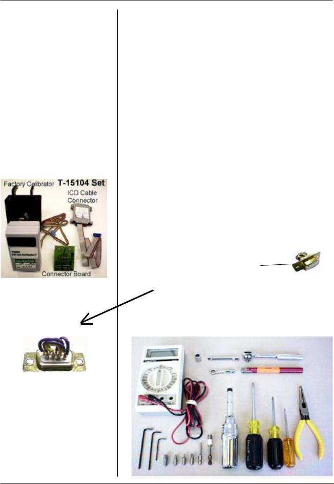
Section 2 - Service
Tools Required for Service Factory Calibration
and Software
Uploading
Photo 1
#1 Flathead screwdriver - 2Ó length #1 Phillips screwdriver - 4Ó length #2 Philips screwdriver - 4Ó length 1/4Ó drive ratchet with 1/4Ó extender 11/32Ó socket
3/32Ó hex key 7/64Ó hex key
Adjustable torque driver - 2 - 14 in/lbs range Bits for Torque Driver:
#1 Phillips
#2 Phillips 3/32Ó hex 7/64Ó hex
1/4Ó square to hex adapter Torque Wrench - Adjustable 2 - 14 in/lbs range Torque Handle: Mountz 06-8002 TB1H 12-21 in/lb or equivalent.
Torque Handle Box Wrench accessory: Mountz 068127 Box Head - 11/32Ó
T15145 - for PRB connector
T15104 - Calibrator and Software Floppy Disc (see Photo 1 at left)
T15810Serial Port Tester
(can be made with a standard DB 9 female with these connections: Pins 1,4,6,9 common
Pins 2,3 common Pins 6,8 common
Digital volt meter ( three plus range) Needle nose pliers
Photo 2
Photo 1b
2 HUMPHREY FDT VISUAL FIELD INSTRUMENT |
SERVICE MANUAL 112120 REV. B |
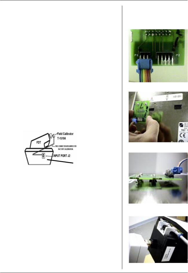
Section 2 - Service
Upgrade recommendation: Upgrade all re- |
|
turned FDTÕs with Software Version 2.10. Perform |
Factory Calibration |
Factory Calibration Process. |
for Software Version. |
|
1.20 or higher |
Start Factory Calibration Process: |
|
1 Turn FDT unit OFF. |
|
2Connect the wire from the T-15102 Factory Calibrator to connector board as shown in Photo 3. Wires must exit from top of connector as shown.
3 |
Remove Visor/Browrest (Sect 4 or 9 for CE FDT) |
|
4 |
Tilt FDT on its side to remove label over Calibration/ |
Photo 3 |
|
||
|
Software loading port J2. |
|
5Align threaded studs of connector board with the two holes near port J2 as shown in Photo 4.
6Insert T 15102 into port J2 as shown in Photo 5. Hookup should be as shown in Figure 1 below.
Fig. 1 |
Photo 4 |
|
|
||
connector board |
|
|
T 15102 |
|
|
7 Position the FDT in upright position and place |
|
|
calibrator onto the slide bracket . See Photo 6 |
|
|
Note: Place calibrator on viewport tightly to prevent |
|
|
light from entering the calibrator housing. |
|
|
8 Turn the FDT ON and view the menu on the LCD: |
Photo 5 |
|
a) Press button next to UTILITIES MENU |
||
|
||
b) Press button next to INSTRUMENT TEST MENU |
|
|
c) Press button next to TEST OUTPUTS |
|
|
d) Press button next to TEST VIDEO MENU |
|
|
e) Press button next to FACTORY CALIBRATION |
|
|
NOTE: Unit can be calibrated with PC utility Calibrat |
|
|
through the FDT computer interface. Refer to the Cali- |
|
|
brate utility for more information. |
|
|
9 Press any button to indicate that you have placed |
Photo 6 |
|
the factory calibrator on the view port. |
||
|
SERVICE MANUAL 112120 REV. B |
HUMPHREY FDT VISUAL FIELD INSTRUMENT 3 |

Section 2 - Service
Factory Calibration for Software Version.
1.20 or higher (continued)
10 Press any button to start the Factory Calibration calibration process. Duration : less than 1minute.
NOTE: Self-Calibrate is automatically performed during Factory Calibration in Version 2.10
11 Turn the FDT OFF and remove calibrator from slide bracket.
12 Remove T-15102 connector board from Port J2 on bottom of FDT. Install a new label part # 112066 over J2 port.
13 Turn FDT ON and view the menu on the FDT LCD:
a)Press the green button until the UTILITIES Menu is reached.
b)Put the black calibration cap on the viewport.
c)Press the button next to RUN SELF CALIBRATION. (Process time: 2 - 3 min.)
Note: A progress indicator will display on the LCD. It will indicate what percentage of the calibration is complete. The unit will indicate when calibration is complete and return to UTILITIES MENU.
14 Now perform a Calibration check:
a)Press button next to INSTRUMENT TEST
MENU.
b)Press button next to TEST OUTPUTS
c)Press button next to TEST VIDEO MENU
d)Press button next to CALIBRATION CHECK
Note: The meter will indicate that the FDT is fully calibrated.
15 Press any button to continue.
16 Press the green button 4 times or until FDT MAIN MENU is reached.
17 Install the visor/browrest with the 4 black hex socket head cap screws as shown in Section 4.
Note: |
See Calibration Limits/Parameters Tables |
|
in this section. |
|
(End of Factory Calibration Process) |
4 HUMPHREY FDT VISUAL FIELD INSTRUMENT |
SERVICE MANUAL 112120 REV. B |
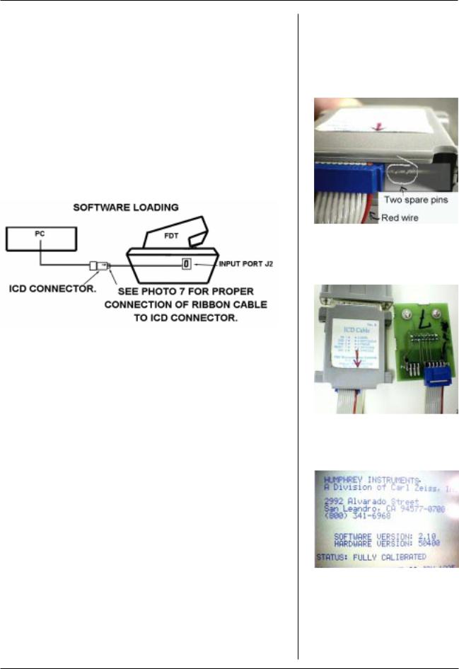
Section 2 - Service
Start Software Loading Process: |
|
1 Connect the ribbon cable to the ICD Cable |
Loading Software for FDT |
|
|
connector as shown in Photo 7 at right. |
Note: FDT software is not |
|
|
Note: a) 2 Pins at right are not used |
Mac compatible. |
b)Align the red wire of the ribbon cable with the red arrow on ICD connector.
2Connect the ribbon cable to the connector board as shown in Photo 8.
3Connect ICD connector to the PC Parallel Port . See Figure 2 below.
Photo 7
Figure 2
4Insert T 15102 into port J2 as shown in Photo 5 and follow software loading instructions displayed on the PC when running FDT Software Installation Program.
|
|
|
Photo 8 |
Note: Whenever installing a new MCU/PCB and |
|
||
|
loading highest revision software, verify proper |
|
|
|
hardware (marked on MCU/PCB) version using |
|
|
|
ÒABOUT FDTÓ. |
LCD Screen will display |
|
|
software/hardware data. See Photo 9 |
|
|
Software Version: |
Release Date: |
|
|
|
Ver. 1.20 |
July 1997 |
|
|
Ver. 2.10 |
October 1997 |
|
Hardware Version: |
Release Date: |
|
|
MCU/PCB Rev 503 |
August 1997 |
Photo 9 FDT LCD Screen |
|
MCU/PCB Rev 504 |
September 1997 |
|
|
Note: |
See Product Updates in this section. |
|
|
SERVICE MANUAL 112120 REV. B |
HUMPHREY FDT VISUAL FIELD INSTRUMENT 5 |

Section 2 - Service
Final Testing
(page 1 of 6)
Note: Follow this final testing process to verify correct operation after the FDT has been serviced.
1. Calibration
Follow instructions in the calibration section of manual.
2. 230 Volt testing
Remove fuse block. Replace the 115v fuses (.315A) with those recommended for 230v.(.160A)
Place fuse block back into unit so the 230v shows. Plug unit into a 230v line and turn unit on. After approximately 10-15 seconds the unit should go through a series of beeps and the FDT Main menu should appear. After this test is done, turn off unit, remove power and replace the fuses with the 115V (.315A) ones. Be sure that the115V shows in the fuse drawer.
3.Operational testing
3.1Plug in PRB.
3.2Turn unit on. After approximately 10-15 seconds the unit will complete self diagnostics and emit two double beeps. The FDT main menu will appear.
3.3Press the button next to UTILITIES MENU.
3.3.1Check the intensity adjustment.
a)Press the button pointing downward. The LCD contrast will decrease.
b)Press the button pointing upward. The LCD contrast will increase.
c)Use both buttons as needed to return to usable LCD contrast.
6 HUMPHREY FDT VISUAL FIELD INSTRUMENT |
SERVICE MANUAL 112120 REV. B |
Section 2 - Service
3.3.2Press the button next to ABOUT FDT. The screen will indicate that the unit is fully calibrated and show the software revision. Make
sure that it has the latest revision software.
3.3.3Press the green button on the bottom left. This should bring you back to the UTILITIES MENU.
3.4Press the button to the left of
INSTRUMENT TESTS MENU.
3.4.1Press the button next to
TEST INPUTS.
a)Press each of the 4 upper left buttons. When each buttons is pressed, the word PRESS to the right of the button will change to a PRESSED highlighted. Release the button. PRESS will reappear unhighlighted.
b)Move the visor to the three different positions - left, middle and right (patients side). The Eye test position on the right hand side of the display will change state to indicate the current eye test position.
c)The Patient button will indicate NOT PRESSED. Press the PRB and it will report a highlighted
PRESSED.
d)Unplug the PRB plug from the PRB jack. The Patient Button status will indicate: Not connected. Plug the PRB plug into the PRB jack.
3.4.2Press the green button on the bottom left to return to
INSTRUMENT TESTS MENU.
Final Testing
(page 2 of 6)
SERVICE MANUAL 112120 REV. B |
HUMPHREY FDT VISUAL FIELD INSTRUMENT 7 |

Section 2 - Service
Final Testing
(page 3 of 6)
3.5Press the button next to TEST OUTPUTS.
3.5.1Press the button next to TEST LCD.
a)Observe highlighted test option on screen.
b)Press button next to RUN TEST. The LCD will reflect state of the highlighted test option.
c)Press any button to exit present LCD test.
d)Press button next to NEXT CHOICE to change test option.
e)Perform the above steps for the CHECKERBOARD,
BLANK SCREEN, FULL SCREEN, AND DIXIE PATTERN options.
f)Press button next to NEXT CHOICE to highlight LCD
MEMORY TEST.
g)Press button next to RUN TEST. The display will be;
Testing LCD memory and change to LCD memory passed. Press any button
to exit test.
h)Press button next to NEXT CHOICE to highlight the
BACKLIGHT option.
i)Press button next to RUN TEST a number of times and observe the LCD screen. The backlight should toggle on and off. Make sure the Backlight is on before exiting this test.
j)Press the green button to return to OUTPUT TESTS.
8 HUMPHREY FDT VISUAL FIELD INSTRUMENT |
SERVICE MANUAL 112120 REV. B |

Section 2 - Service
3.5.2Press the button next to TEST
VIDEO MENU.
a)Press the button next to
TEST VIDEO SYSTEM.
b)Look into the patient viewing area. A large flashing circle exhibiting the Model 710 Series grating pattern in the center of the viewing area will be visible.
c)Press the Green button to return to TEST VIDEO MENU.
3.5.3Press the button next to AMBIENT
LIGHT CHECK.
a)There may be a short time for monitor warm up.
b)With the calibration cap on, the pointer will be in the dark range.
c)Remove the calibration cap. The pointer will rise to
the light or bright range, depending upon the intensity of the room lighting.
d)Put the calibration cap back on and press the green button to return to TEST VIDEO MENU.
3.5.4Put Calibration cap on. Press button next to CALIBRATION
CHECK.
NOTE:Calibration will be denied if cap is off and room light level is too high.
a)The pointer should be in the fully calibrated range.
b)Do not press the factory calibration option. If this option is accidentally chosen, the unit will detect that a calibrator is not attached and warn user.
c)Press the green button twice to return to OUTPUT
TESTS MENU.
Final Testing
(page 4 of 6)
SERVICE MANUAL 112120 REV. B |
HUMPHREY FDT VISUAL FIELD INSTRUMENT 9 |

Final Testing
Section 2 - Service
Final Testing
(page 5 of 6)
Photo 10
3.6Press the button next to TEST SPEAKER.
3.6.1There will be increasing tones.
3.7Press the button next to TEST PRINTER
MENU.
3.7.1The TEST PRINTER MENU will be displayed. Press the button next to
RUN PRINTOUT TEST. The FDT will print out a series of patterns and instrument data.
3.7.2Press the button next to ADVANCE PAPER. The paper will
advance about 1-2 inches beyond the slot in the paper door.
3.7.3Press the button next to PRINTER
STATUS. ÒPRINTER OKÓ message will appear.
3.7.4Press the green button 3 times to return to INSTRUMENT TESTS
MENU.
3.8Press the button next to TEST SERIAL PORT.
3.8.1Press any of top four buttons to execute test.
3.8.2Both the data transfer and hand shaking test should fail.
3.8.3Press the green button to return to
INSTRUMENT TESTS MENU.
3.8.4Place T-15810 into the serial port on bottom of unit. See Photo 10.
3.8.5Press the button next to TEST SERIAL PORT.
a)Press any of top four buttons to execute tests.
b)LCD will display:
DATA TRANFER PASSED HANDSHAKING PASSED
10 HUMPHREY FDT VISUAL FIELD INSTRUMENT |
SERVICE MANUAL 112120 REV. B |

Section 2 - Service
3.8.6Press the green button twice to return to INSTRUMENT TESTS
MENU.
3.8.7Remove T-15810.
3.9Press the button next to A/D CIRCUITRY.
3.9.1A reading will come up for Mean gray and printhead tem-
perature. If the unit fails this test a malfunction error will appear.
3.10Perform a screening test to check unit operation.
3.11Turn unit off.
4.Agency testing
4.1Hypot
Testing at 1500VAC for one second. Apply the voltage between primary wiring (supply terminals connected together) and accessible dead metal parts without breakdown indication.
4.2 Ground continuity
Total resistance of the product shall not exceed 0.2 ohms (2.0VDC). The test will be conducted using a 10 amp DC current source with a no load voltage no greater than 6.0VDC for five seconds. Measure ment will be taken from the grounding pin of the power supply cord to the accessible metal part of the product.
4.3 Leakage current
The leakage current measured from any exposed grounded metal parts to the grounding pin of the power supply cord shall not exceed 100 microamps, AC RMS (95.5MVAC RMS) with input voltage set to 120VAC, 60HZ or 240VAC, 50HZ.
If a FTD fails any test in this section, set it aside for troubleshooting and repair. When the FDT is repaired and passes all the tests, place a label over the calibration port.
Final Testing (Page 6 jof 6)
Hypot, Ground Continuity,
and Leakage Current
Testing
(For In-House use only.)
SERVICE MANUAL 112120 REV. B |
HUMPHREY FDT VISUAL FIELD INSTRUMENT 11 |

Section 2 - Service
Important Shipping
Information
Note: |
Install a new roll of paper. |
|
Install the paper roll foam before |
|
packing the unit for shipping. See |
|
photo at left. This foam strip (called |
|
foam shipping wedge in UserÕs Guide) |
|
prevents the paper roll from unwinding |
|
during shipping. |
|
Return all of the customerÕs |
|
accessories. |
Paper roll foam prevents un-winding during shipping
12 HUMPHREY FDT VISUAL FIELD INSTRUMENT |
SERVICE MANUAL 112120 REV. B |

Section 2 - Service
Calibration Limits Information
Table A:Calibration Parameters Printed on the System Status Report
Parameter |
Nominal |
SW |
Expected |
Expected |
SW |
Comments/Description |
F.C.** |
S.F.*** |
|
|
Limit |
Min |
Max |
Limit |
|
|
|
|
|
Min |
|
|
Max |
|
|
|
|
|
|
|
|
|
|
|
|
SCAN LINE |
*90 |
6 |
*60 |
*110 |
235 |
Reflects mechanical alignment of |
X |
|
(internal) |
photodetector to CRT. |
|
||||||
|
|
|
|
|
|
|
||
|
|
|
|
|
|
|
|
|
GAMMA |
*2.35 |
1.0 |
*2.2 |
*2.5 |
<3.0 |
CRT response correction |
|
X |
exponent. |
|
|||||||
|
|
|
|
|
|
|
|
|
|
|
|
|
|
|
|
|
|
REFERENCE |
NA |
0 |
*15 |
*60 |
255 |
Adjusts for CRT aging. |
|
X |
POT |
(new CRT) |
(new CRT) |
( *150 expected max on old CRT) |
|
||||
|
|
|
|
|
||||
|
|
|
|
|
|
|
|
|
INTERNAL |
|
|
|
|
|
Absolute value read from Internal |
|
|
*2250 |
0 |
*1500 |
*3000 |
4095 |
photodetector ADC when CRT is |
X |
|
|
TARGET |
|
|||||||
|
|
|
|
|
200 c/m^2. |
|
|
|
|
|
|
|
|
|
|
|
|
|
|
|
|
|
|
|
|
|
DC OFFSET |
30 |
0 |
*10 |
*50 |
1023 |
DC offset on internal |
X |
|
photodetector signal. |
|
|||||||
|
|
|
|
|
|
|
|
|
|
|
|
|
|
|
|
|
|
|
Internal |
|
|
|
|
Absolute value read from Internal |
|
|
INTERNAL |
|
Internal |
Internal |
|
photodetector ADC when CRT is |
|
|
|
Target |
0 |
4095 |
|
|
||||
PEAK |
Target - 40 |
Target + 40 |
as close to 200 c/m^2 as the |
|
|
|||
|
|
|
|
|
||||
|
|
|
|
|
|
reference pot can adjust. |
|
|
|
|
|
|
|
|
|
|
|
* These numbers are approximate and have not been verified by statistical tracking.
** Adjusted during Factory Calibration
***Adjusted during Self Calibration
Table B:Calibration Parameters to LCD and Serial Port: Factory Calibration
Message |
Expected Limits |
Comment |
|
|
|
|
|
INTERNAL PEAK |
NA |
This is a transeint message that reports DAC settings. |
|
|
|
|
|
External |
|
|
|
Photo Sensor Stop |
*40 min, *70 nom, *100 max |
Two passes: Second pass should be within 16 of first. |
|
Line |
|
|
|
|
|
|
|
External Photosensor |
3000+/- 20 |
External target 3000 = 200c/m^2. This is how close the |
|
reference pot gets to 200 c/m^2. |
|||
|
|
||
|
|
|
|
DC OFFSET |
Same as in table (A) above. |
Same as in table (A) above. |
|
|
|
|
|
Internal Photosensor |
Same as SCAN LINE in table |
Same as in table (A) above. |
|
Stop Line |
(A) above. |
||
|
|||
|
|
|
|
Internal Photosensor |
Same as INTERNAL TARGET |
Same as in table (A) above. |
|
in table (A) above. |
|||
|
|
||
|
|
|
* These numbers are approximate and have not been verified by statistical tracking.
SERVICE MANUAL 112120 REV. B |
HUMPHREY FDT VISUAL FIELD INSTRUMENT 13 |

Section 2 - Service
Calibration Limits Information
Table C:Calibration Parameters to LCD and Serial Port: Self Calibration
Message |
Expected Limits |
Comment |
|
|
|
|
|
Internal Photosensor |
Same as INTERNAL TARGET |
Same as in table (A) above. |
|
in table (A) above. |
|||
|
|
||
|
|
|
|
|
82 max allowed by SW |
Keep unit as dark as possible. If this fails in dark, unit |
|
Ambient Light |
is broken, or DC offset is bad - Factory calibration |
||
(2% of full brightness) |
|||
|
needed. |
||
|
|
||
|
|
|
|
REFERENCE POT |
Same as REFERENCE POT in |
Same as in table (A) above. |
|
table (A) above. |
|||
|
|
||
|
|
|
|
Dynamic Range |
82 min allowed by SW (50:1) |
Full screen brightness to zero screen brightness ratio. |
|
|
|
|
|
Gamma Factor |
Same as in GAMMA |
Same as in table (A) above. |
|
CORRECTION in table (A) above. |
|||
|
|
||
|
|
|
|
|
Second Column is limited to 120 |
First column is linear ramp target value written to |
|
Linearity |
DAC. Second column is photodetector reading |
||
(3% deviation from straight line) |
|||
|
deviation from the linear ramp. Scale is 127 - 4095. |
||
|
|
||
|
|
|
* These numbers are approximate and have not been verified by statistical tracking.
14 HUMPHREY FDT VISUAL FIELD INSTRUMENT |
SERVICE MANUAL 112120 REV. B |

Section 2 - Service
Product Updates
Effectivity |
S/N Cut-In |
DOMESTIC FDT UNITS : |
|
Description of Changes for 00710-11 |
|||
|
|
||
|
|
|
|
|
|
Sales Demo Units (all S#>9700199 and |
|
|
|
9701000) . Monitor needs rework at some time |
|
7/97 |
S#9700200 |
to extend calibration life. |
|
|
|
SW Version 8.30. |
|
|
|
HW Version 50300 (MCU PCB 112037-503) |
|
|
|
|
|
|
|
Initial Production units for end users (all |
|
8/97 |
S#9701000 |
S#>9701000). SW Version 1.20. |
|
|
|
HW Version 50300 (MCU PCB 112037-503) |
|
|
|
|
|
8/29/97 |
~S#9701145 |
Color changes of housings:cream to gray. |
|
|
|
|
|
9/11/97 |
S#9701199 |
HW version 50400 (MCU PCB 112037-504 for |
|
CE) |
|||
|
|
||
|
|
|
|
9/15/97 |
~S#9701210 |
Calibration Caps (pn112078-1) Started shipping |
|
|
|
with instruments. |
|
10/3/97 |
S#9701294 |
SW Version 2.10 (Language translations) |
|
|
|
|
|
|
CE INTERNATIONAL FDT UNITS : |
|
Effectivity |
S/N Cut-In |
Description of Changes for 00710-X1 (X=2-9) |
|
Note:Domestic S#'s have a 0 in the 3rd digit, |
|||
|
|
||
|
|
International S#'s have a 3) |
|
|
|
|
|
|
|
Initial International Production units (all |
|
9/97 |
S#9731000 |
S#'s>9731000) |
|
SW Version 1.20. |
|||
|
|
||
|
|
HW version 50400 (MCU PCB 112037-504 for CE) |
|
|
|
|
|
|
S#9731025 |
|
|
|
(also |
|
|
10/3/97 |
S#9731019 |
SW Version 2.10 (language translations) |
|
and |
|||
|
|
||
|
S#9731023 |
|
|
|
are Ver. 2.10 |
|
|
|
|
|
SERVICE MANUAL 112120 REV. B |
HUMPHREY FDT VISUAL FIELD INSTRUMENT 15 |
 Loading...