

START-UP
Carl Zeiss Initial start-up Axio Imager
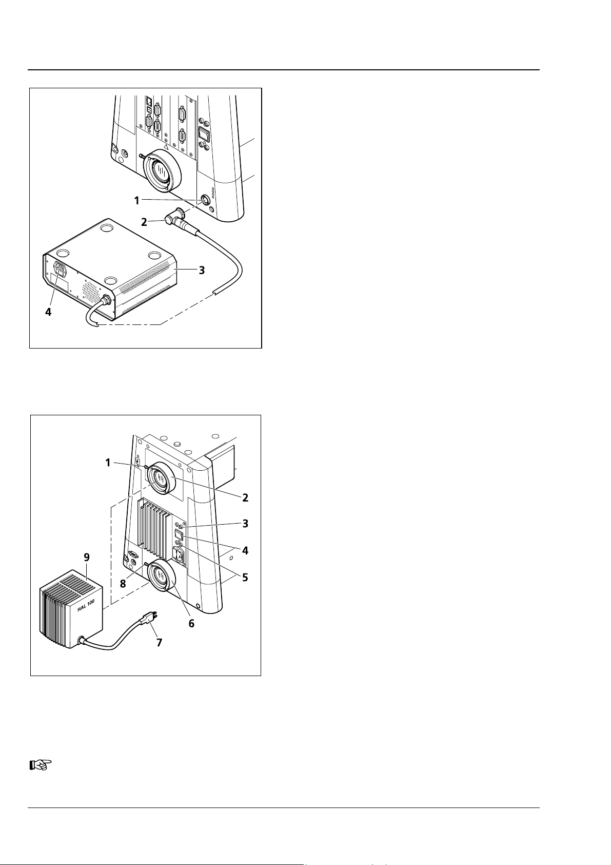
3.1.10.2 Motorized stand
• Plug connecting plug (3-12/2) of power supply
230 (3-12/3) into the corresponding connector
(3-12/1) on the rear side of the stand.
• Plug the power cable first into the power
connector (3-12/4) of the power supply 230
and then into a power outlet. The power supply
can be connected to a line voltage of 100 …
127 or 200 … 240 VAC, 50/60 Hz. The power
unit is set automatically to the line voltage
available.
Fig. 3-12 Axio Imager, motorized
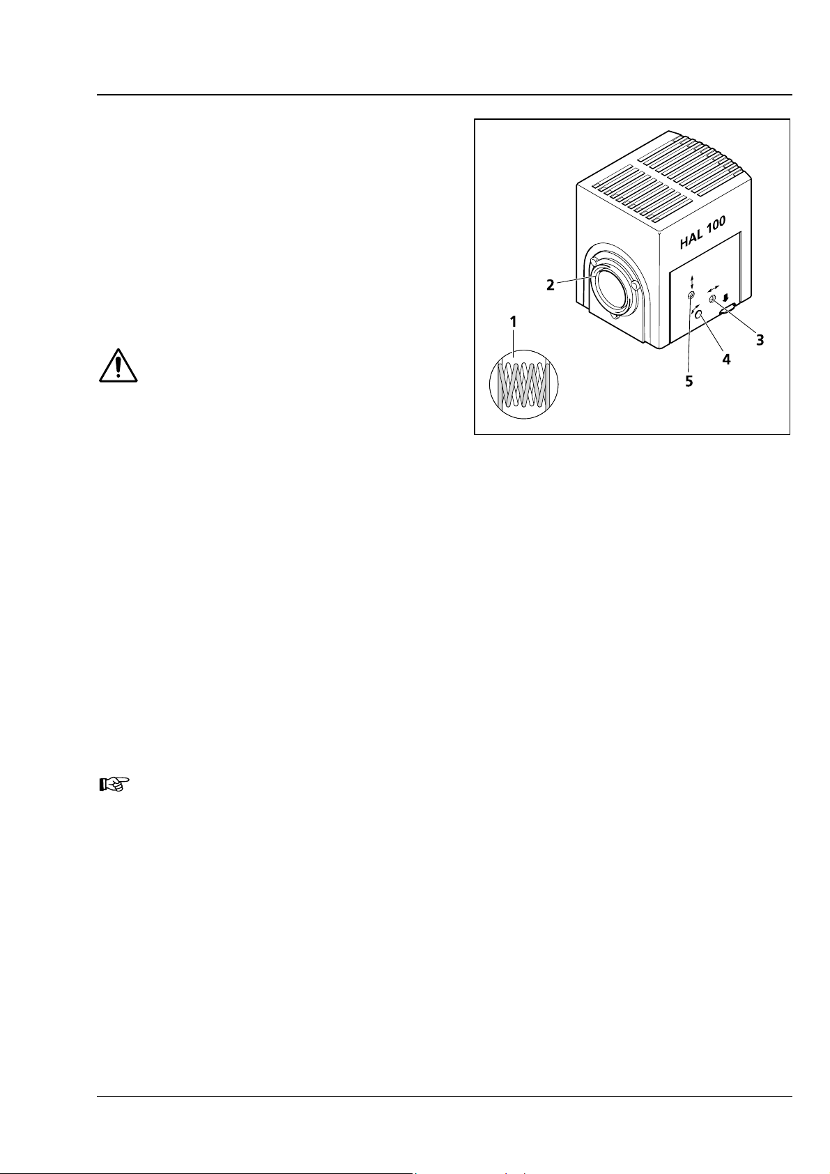
3.1.11 HAL 100 halogen illuminator
The HAL 100 illuminator is used as light source for
transmitted-light and reflected-light techniques
(except fluorescence) on the Axio Imager.
Attachment to the reflected-light or transmittedlight socket is performed analogously.
3.1.11.1 Attaching the HAL 100 halogen
illuminator
• Remove the protective cap from the reflected-
light or transmitted light socket.
• Insert the dovetail mount of the lamp housing
(3-13/9) into the corresponding socket (3-13/2
or 3-13/6) and, using the SW 3 ball-headed
screwdriver, tighten it with clamping screw
(3-13/1 or 3-13/8).
• Insert 3-pole lamp plug (3-13/7) into 3-pole
Fig. 3-13 Attaching the HAL 100 halogen
illuminator
The light manager functionality depends on the position of the toggle switch.
12 V/100 W connector (3-13/3 – for reflected
light or 3-13/5 - for transmitted light) on the
back of the instrument.
• Switch the toggle switch for transmitted/
reflected light (3-13/4) to the required position.
32 B 46-0046 e 04/05
START-UP
Axio Imager Initial start-up Carl Zeiss
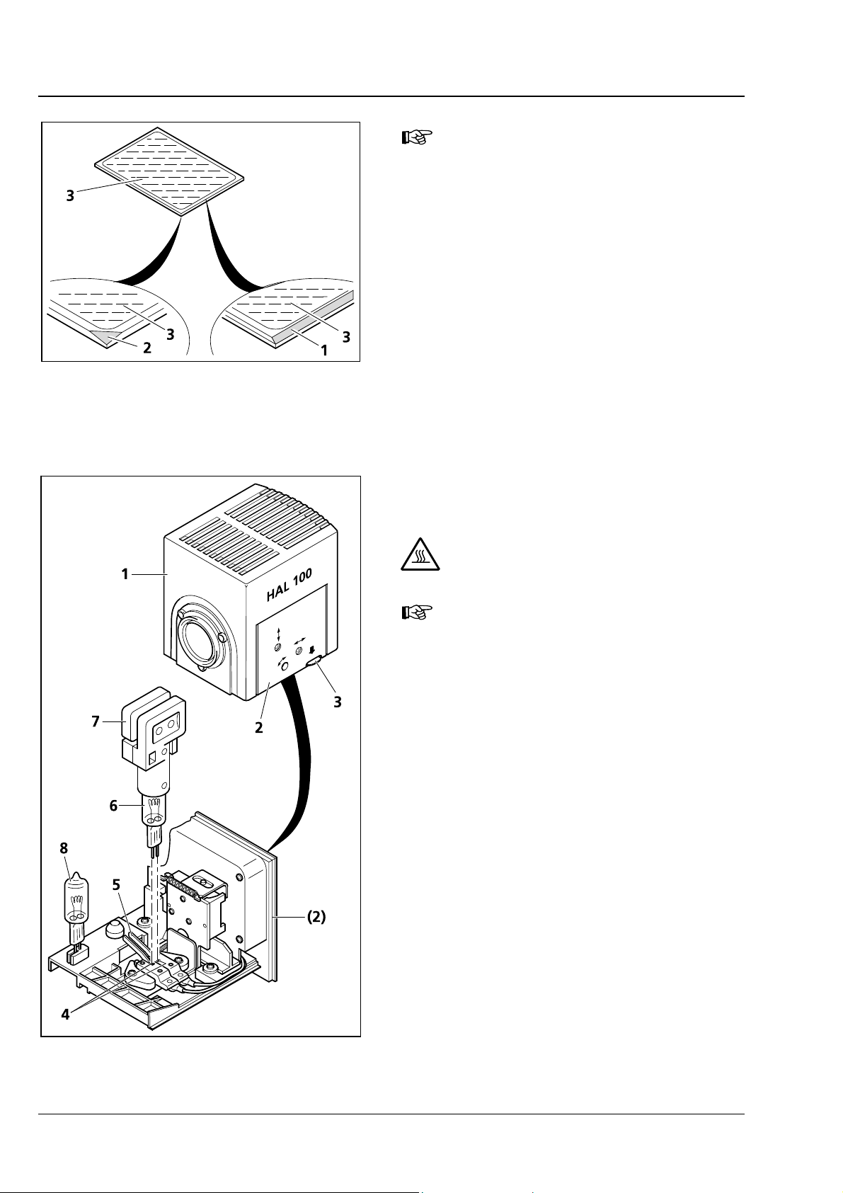
3.1.11.2 Adjusting the HAL 100 halogen
illuminator
(1) Coarse adjustment
• Loosen clamping screw (3-13/1 or 3-13/8) and
remove the operational halogen illuminator
from the microscope stand.
• Switch on microscope as described in Section
4.3.
• Direct the light beam to a projection surface
(wall) that is at least 3 m away.
Do not look into the light exit aperture
of the illuminator.
• Using the SW 3 ball-headed screwdriver turn
adjusting screw (3-14/3) until both images of
the lamp filament appear as sharp as possible
on the projection surface.
• Then, turn adjusting screws (3-14/4 and 5) until
the lamp filament of one image exactly fills the
gaps of the reflected filament image (3-14/1).
Fig. 3-14 Adjusting the HAL 100 halogen
illuminator
(2) Fine adjustment
• Reattach the microscope illuminator to the microscope stand and lock it with the clamping screw.
• Move diffusion disk for reflected or transmitted light out and remove the filter wheels from the
respective slot.
• With an objective of ≤ 40x, focus on the specimen and search for a free place on the specimen.
• Remove eyepiece and, in the pupil image visible in the eyepiece socket, center the lamp filament and
its reflection with adjusting screws (3-14/4 and 5).
• Using adjusting screws (3-14/3) optimize the evenness of illumination of the pupil image.
It is advisable to use the adjusting aid (4-1/5) for fine adjustment of the halogen illuminator
mounted to the reflected-light socket. After pulling out the adjusting aid, the lamp filament
and its reflection can be viewed directly in its viewing glass.
• Move the diffusion disk in and reinsert the filter wheels.
B 46-0046 e 04/05 33
START-UP
Carl Zeiss Attachments and conversions Axio Imager
The reflective (coated) side (3-38/3) of
the beam splitter has a beveled edge
(3-38/1) or corner (3-38/2).
• Place the excitation half of the module
(3-37/1) onto the emission half (3-37/4)
(retaining pins 3-37/5b and eyelets 3-37/5a
mesh with one another). Hold both halves
together and turn them back into the
installation position.
• Re-insert the slotted screws and tighten them
Fig. 3-38 Marks on beam splitter
up.
• Finally, affix the adhesive label with the name of
the filter combination to the side of the module.
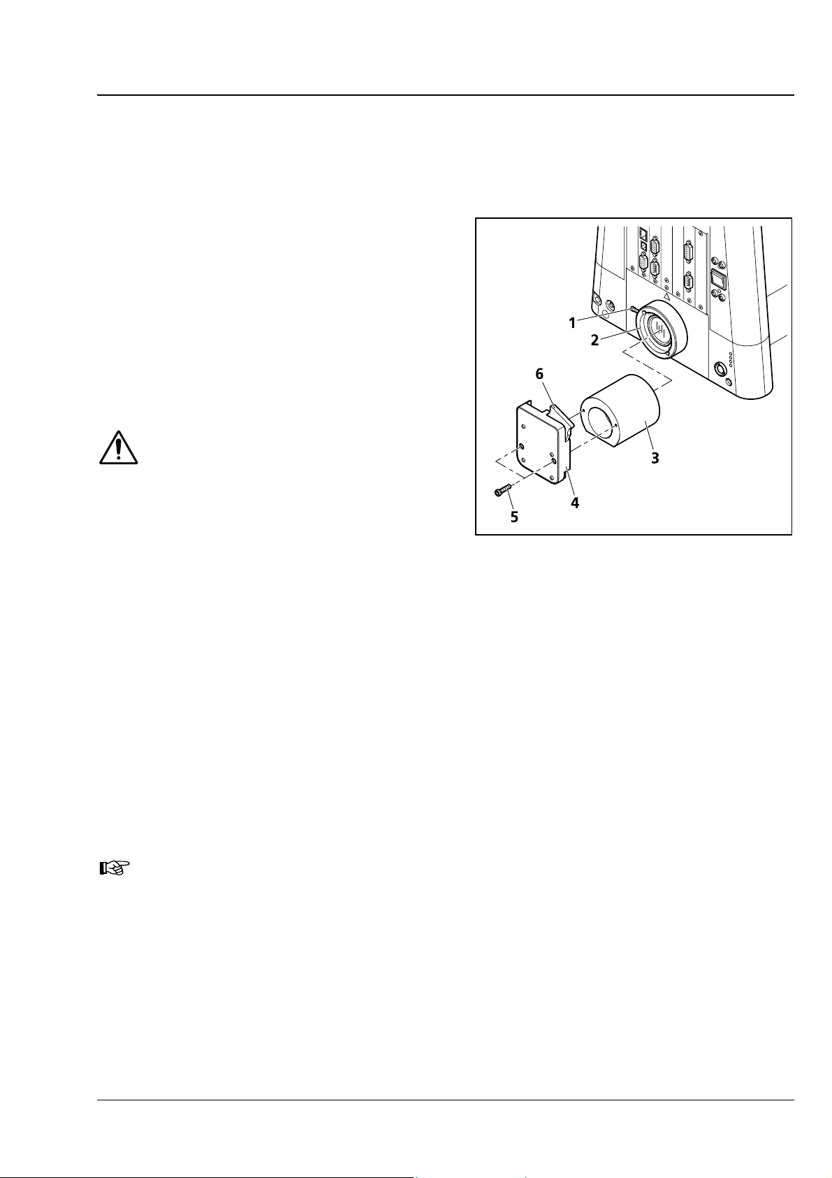
3.2.10 Replacing the HAL 100 halogen
lamp
CAUTION
Hot surface!
You need not remove the lamp
housing from the stand to replace the
halogen lamp. Do not store the
supplied tool for lamp replacement in
the lamp housing while the illuminator
is operating.
The replacement lamp (3-39/8) may
remain put on in the lamp housing.
• Switch off the microscope as described in
Section 4.3, disconnect plug (3-13/7) from
connector12 V/100 W (3-13/3 – reflected light
or 3-13/5 – transmitted light) and allow for a
cool down of approximately 15 minutes.
• Depress unlock button (3-39/3) of halogen
illuminator HAL 100 (3-39/1), fully pull out lamp
carrier (3-39/2) and put it down separately.
• Depress both spring levers (3-39/5) and remove
the old halogen lamp (3-39/6) upward. Always
hold/grasp the halogen lamp by means of the
replacement tool (3-39/7), as even traces of
grease on the lamp may affect its lifetime.
• Depressing both spring levers insert the new
Fig. 3-39 Changing the halogen lamp
lamp in the lamp socket (3-39/4) and release
the spring levers.
50 B 46-0046 e 04/05
START-UP
Axio Imager Attachments and conversions Carl Zeiss
• Briefly, depress the spring levers once more thus centering the lamp.
• Reattach the lamp carrier sliding it in until it snaps in noticeably.
3.2.11 Installing the LED illuminator for
transmitted light
The LED illuminator for transmitted light can be
installed optionally on the transmitted light port on
the rear side of the instrument or on the bottom of
the condenser carrier.
The LED illuminator delivers light of constant color
temperature independent of the set light intensity.
CAUTION
The LED illuminator is a Class 2 laser
device. Do not look directly into the
LED light.
Fig. 3-40 Installing the LED illuminator
Installing the LED illuminator on the transmitted light port
• Loosen clamping screw (3-40/1) on transmitted-light port (3-40/2). Remove the halogen lamp.
• Disconnect the illuminator plug from the 12 V/100 W connector (transmitted light) on the back of the
instrument.
• Insert adapter optics for LED illuminator (3-40/3) in the transmitted-light port with the slant pointing
down and tighten the clamping screw.
• Screw LED illuminator (3-40/4) onto the adapter optics using the provided Allen screws (3-40/5).
• Push slider with diffusion disk 10° (3-40/6) into LED illuminator.
• Plug the plug of the LED illuminator into the 12 V/100 W connector (transmitted light) on the back of
the instrument.
You can change the color temperature for specimen observation by inserting color
temperature filters in the slider with diffusion disk (to be held by retaining ring).
B 46-0046 e 04/05 51
 Loading...