


Axiolab A
Reflected-Light
Microscope
Operating Manual

Carl Zeiss Axiolab A
Knowledge of this instruction manual is necessary for device operation. Please get familiar with its
contents and especially the precautions for safe device operation.
Changes due to further technical development are reserved; this manual is not covered by an update
service.
© Unless expressly authorized, forwarding and duplication of this document, utilization and
communication of its contents are not permitted. Violations will entail an obligation to pay
compensation.
All rights reserved in the event of granting of patents or registration of an utility model.
Issued by:
Number of this operating manual: B 40-015 e
Date of issue: 06/99
II B 40-015 e 06/99
Carl Zeiss
Microscopy
D-07740 Jena
Phone: ++49-36 41 64-16 16
Telefax: ++49-36 41 64-31 44
E-mail: micro@zeiss.de
Internet: www.zeiss.de/micro

Axiolab A Carl Zeiss
CONTENTS
Page
INTRODUCTION................................................................................................................. I
Title Page ............................................................................................................................ I
Copyright........................................................................................................................... II
Contents ............................................................................................................................III
List of Illustrations...............................................................................................................V
Notes ................................................................................................................................ VI
Hints on Instrument Safety................................................................................................ VII
Overall View of the Axiolab A Reflected-Light Microscope....................................................X
1 DESCRIPTION................................................................................................................. 1-1
1.1 Name; Intended Application,............................................................................................1-2
1.2 Instrument Description.....................................................................................................1-2
1.3 Microscope Configurations and Modules..........................................................................1-5
1.4 Function Elements (see Fig. 1-5, after this table) .............................................................1-12
1.5 Objectives......................................................................................................................1-18
1.6 Eyepieces.......................................................................................................................1-19
1.7 Stage Micrometers and Eyepiece Reticles........................................................................ 1-20
1.8 Technical Data...............................................................................................................1-22
2 START-UP.......................................................................................................................2-1
2.1 Unpacking the Instrument................................................................................................2-3
2.2 Screw in Objectives..........................................................................................................2-3
2.3 Insertion of Eyepieces ......................................................................................................2-4
2.3.1 Insertion of Eyepiece Reticle.............................................................................................2-4
2.3.2 Compensation of Ametropia when Eyepiece Reticles are used .......................................... 2-5
2.4 Setting of Interpupillary Distance......................................................................................2-5
2.5 Attachment of Reflected-Light Halogen Illuminator........................................................... 2-6
2.6 Retrofit the Transmitted-Light Halogen Illumination ..........................................................2-6
2.6.1 Switch on the Transmitted-Light Halogen Illuminator........................................................ 2-7
2.7 Equipment of Filter Slider................................................................................................. 2-7
2.8 Set the Luminous-Field Diaphragm...................................................................................2-8
2.9 Connecting the Instrument to the Line............................................................................. 2-8
B 40-015 e 06/99 III

Carl Zeiss Axiolab A
Page
3 OPERATION................................................................................................................... 3-1
3.1 Switch on the Instrument ................................................................................................ 3-3
3.2 Illumination and Contrasting Techniques.......................................................................... 3-4
3.2.1 Setting of Reflected-Light Brightfield................................................................................ 3-4
3.2.2 Setting of Reflected-Light Polarization.............................................................................. 3-5
3.2.3 Setting of Transmitted-Light Polarization with extended Polarization Equipment ............... 3-5
3.2.4 Setting of Epi-Fluorescence............................................................................................ 3-13
3.2.5 Setting of Transmitted-Light Brightfield (KÖHLER Illumination)........................................ 3-14
3.3 Attachment of Microscope Stages and Specimen Holders............................................... 3-15
3.3.1 Attachment of Pol Rotary Stage..................................................................................... 3-16
3.4 Use of Polished Section Attachment............................................................................... 3-17
3.5 Photomicrography and Videomicroscopy........................................................................ 3-18
3.5.1 Attachment of Photomicrography Equipment ................................................................ 3-19
3.5.2 Attachment of Adapters for Video Cameras................................................................... 3-22
3.6 Insertion of 8× Drawing Eyepiece................................................................................... 3-24
4 CARE, TROUBLESHOOTING AND SERVICE ................................................................... 4-1
4.1 Maintenance of the Instrument ....................................................................................... 4-3
4.2 Troubleshooting.............................................................................................................. 4-4
4.3 Requesting Service ..........................................................................................................4-6
ANNEX...........................................................................................................................A-1
List of Abbreviations........................................................................................................A-3
Certification in Accordance with DIN EN ISO 9001 / DIN EN 46001 ...................................A-5
EC Conformity Declaration .............................................................................................. A-7
IV B 40-015 e 06/99

Axiolab A Carl Zeiss
LIST OF ILLUSTRATIONS
Page
Fig. 1-1 Axiolab A main modules ..................................................................................................1-3
Fig. 1-2 Optical design of the Axiolab A with transmitted-light equipment..................................... 1-4
Fig. 1-3 Axiolab A microscope configurations................................................................................1-6
Fig. 1-4 Axiolab A accessories..............................................................................................1-8, 1-10
Fig. 1-5 Axiolab A function elements .................................................................................1-16, 1-17
Fig. 2-1 Unpacking the instrument................................................................................................2-3
Fig. 2-2 Screw in objectives .......................................................................................................... 2-3
Fig. 2-3 Insertion of eyepiece reticle..............................................................................................2-4
Fig. 2-4 Attachment of reflected-light halogen illuminator............................................................. 2-6
Fig. 2-5 Equipment of filter slider.................................................................................................. 2-7
Fig. 2-6 Setting the luminous-field diaphragm...............................................................................2-8
Fig. 2-7 Connecting the instrument to the line.............................................................................. 2-9
Fig. 3-1 Switch on the instrument.................................................................................................3-3
Fig. 3-2 Setting of reflected-light brightfield..................................................................................3-4
Fig. 3-3 Setting of reflected-light polarization ...............................................................................3-5
Fig. 3-4 Centering of objectives ....................................................................................................3-6
Fig. 3-5 Setting of transmitted-light polarization ...........................................................................3-7
Fig. 3-6 Determine the n
vibration direction using the example of an artificial fiber...................... 3-8
γ
'
Fig. 3-7 Schematic diagram of the color chart in addition and subtraction position ........................3-8
Fig. 3-8 Determine the optical character of crystals ..................................................................... 3-11
Fig. 3-9 Setting of epi-fluorescence.............................................................................................3-13
Fig. 3-10 Setting of transmitted-light brightfield ...........................................................................3-14
Fig. 3-11 Stage selection .............................................................................................................. 3-15
Fig. 3-12 Changing the microscope stage.....................................................................................3-15
Fig. 3-13 Pol rotary stage- setting of specimen mount and stop ....................................................3-16
Fig. 3-14 Use of polished section attachment................................................................................ 3-17
Fig. 3-15 Attach various camera systems to the Axiolab A phototube............................................3-18
Fig. 3-16 Attachment of SLR camera, e.g. CONTAX 167 MT .........................................................3-19
Fig. 3-17 Attachment of MC 80
...............................................................................................3-21
DX
Fig. 3-18 Insertion of 8× drawing eyepiece....................................................................................3-24
B 40-015 e 06/99 V

Carl Zeiss Axiolab A
Fig. 4-1 Changing the fuses ......................................................................................................... 4-4
Fig. 4-2 Changing the 6 V, 30 W reflected-light halogen illuminator ............................................. 4-5
Fig. 4-3 Changing the 6 V, 30 W transmitted-light halogen lamp.................................................. 4-6
NOTES
The figures integrated in the text each have a figure number and a caption, e.g. ”Figure 2-7”
•
signifies: the figure in Section 2 with the serial number 7. In each figure, details discussed in the text
have been assigned with a reference line marking and an item number. In the running text, ”Mains
cable (2-7/1)” signifies: in Figure 7 of Section 2, the mains cable is marked with the item number 1.
Refer to the annex for explanations of the abbreviations.
•
This instruction manual refers to the Axiolab A microscope equipment including accessories (see page
•
1-5 following).
This manual can also be used for other instrument versions.
VI B 40-015 e 06/99
Axiolab A Carl Zeiss
Notes on Instrument Safety
The Axiolab A reflected-light microscope was designed, produced and tested in compliance with DIN
61010-1 (IEC 1010-1), Safety requirements for electrical measuring, control and laboratory instruments,
and meets the requirements of appendix I of directive 73/23/EC and the relevant CSA and UL directives.
The instrument meets the requirements of the EC directive 89/336/EC and the EMC legislation of
November 9th 1992. This operation manual includes information and warnings which must be observed
by the user.
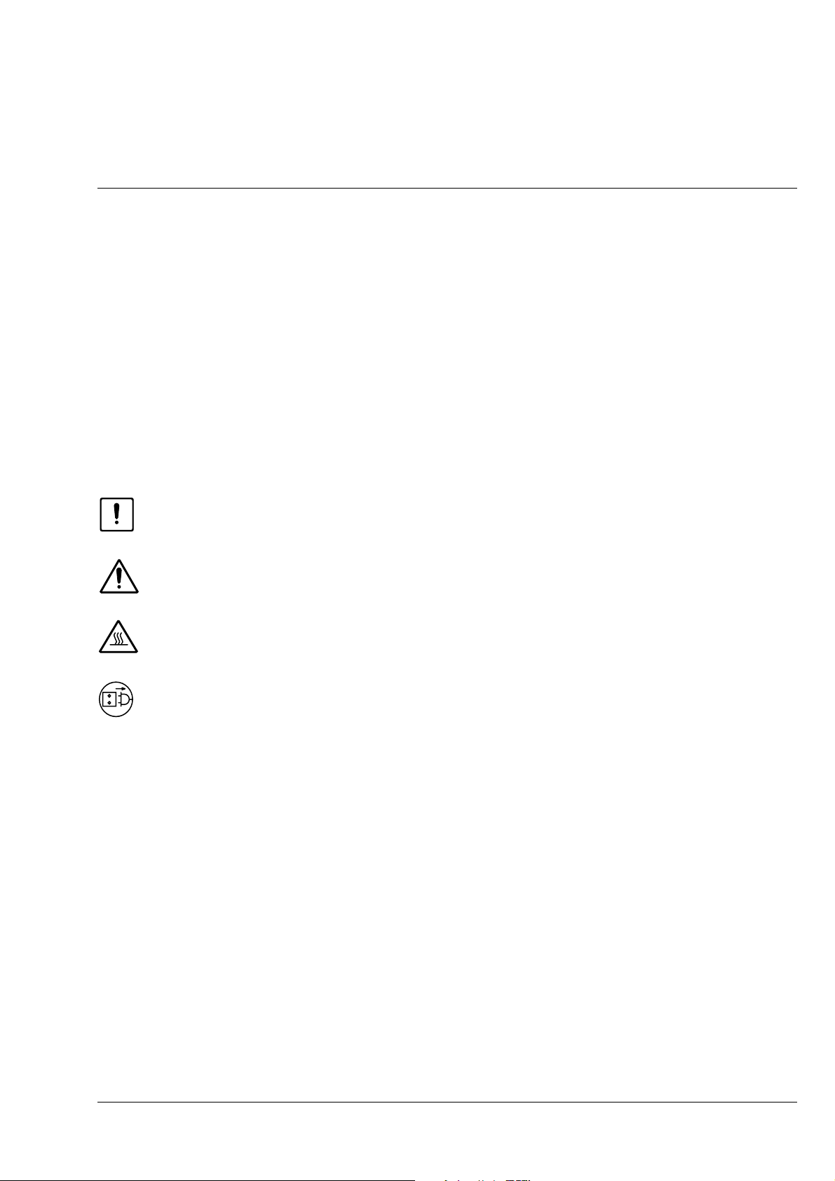
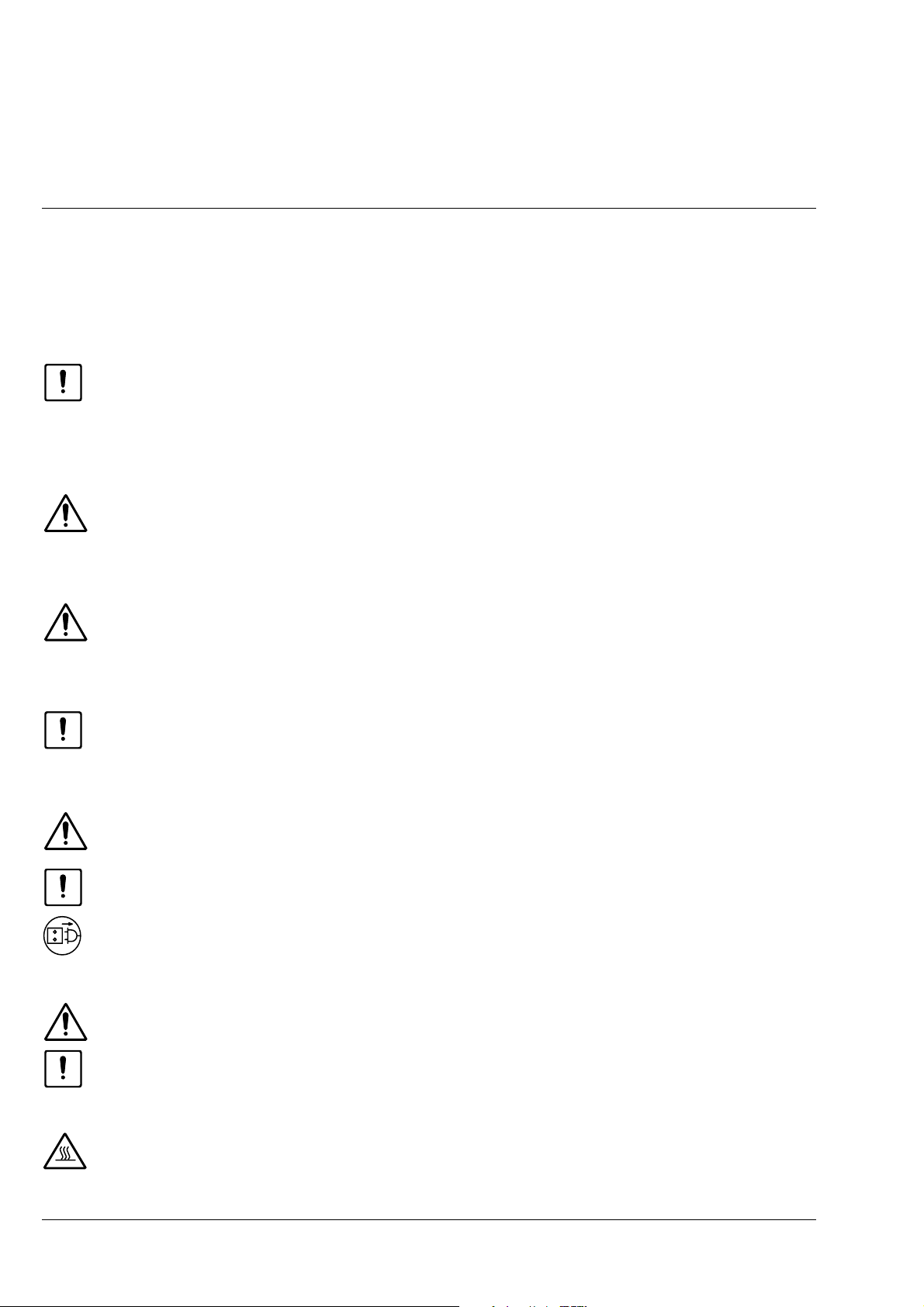
The following warning and information symbols are used in this manual:
☞
NOTE
This symbol is a warning which you must observe under all circumstances.
CAUTION
This symbol is a warning which indicates a hazard to the instrument or instrument system
CAUTION
This symbol is a warning which indicates a hazard to the user of the instrument
CAUTION
Hot surface
CAUTION
Disconnect the instrument from the line before opening it!
!
.
.
B 40-015 e 06/99 VII
Carl Zeiss Axiolab A
The Axiolab A microscope, including original accessories, may only be used for the microscope
techniques described in this manual.
Particular attention must be paid to the following warning notes:
The manufacturer cannot assume any liability for any other applications, possibly also involving
individual modules or single parts. This also applies to all service or repair work which is not
carried out by authorized service personnel. Furthermore, this forfeits all the claims against
warranty.
The power plug must be inserted in a socket featuring a grounding (earth) contact. The
grounding effect must not be made ineffective by an extension cable which does not have a
protective ground wire.
If it is established that the protection measures are no longer effective, the instrument must be
switched off and safeguarded against inadvertent operation. Please contact your local
Carl Zeiss service agency or the Carl Zeiss microscopy service for the repair of the instrument.
The wide range power unit which is integrated in the stand of the microscope permits the use
of line voltages in the range between 100 and 240 V AC ± 10%, 50 - 60 Hz, without the need
for the voltage to be changed at the instrument.
Always disconnect the instrument from the line before opening the instrument and before
changing the fuses.
Make sure to use only fuses of the rated power required. The use of makeshift fuses and the
short-circuiting of the fuse holders are not permitted.
The Axiolab A microscope is not equipped with any special devices for protection from
substances which are corrosive, toxic, radioactive or otherwise hazardous to health. All the
legal regulations for accident prevention, particularly those in the respective countries, must be
observed when handling such substances.
Avoid touching the hot lamp housing. Always pull the power plug before changing the lamps
and allow the instrument to cool down for approx. 15 mins.
VIII B 40-015 e 06/99
Axiolab A Carl Zeiss
Dust and dirt can impair the performance of the instrument. Therefore, the instrument must be
protected against these influences as far as possible, and covered with the dust cover if it is not
used for longer periods of time. Always check whether the instrument is switched off before
you cover it.
Placing objects against or covering ventilation slats can lead to a build-up of heat which will
damage the instrument and, in extreme cases, cause a fire. Always keep the ventilation slats
clear and make sure that no objects enter the instrument through the ventilation slats.
The instruments must be operated by trained personnel only who must be aware of the
possible danger involved with microscopy and the relevant application. The Axiolab A is an
optical precision instrument which can be impaired in its performance or damaged when
handled improperly.
Notes on warranty
The manufacturer guarantees that the instrument has no material and production defects when
delivered. You must inform us of any defects immediately and we must do anything to minimize the
damage. If the manufacturer is informed of such a defect, he is obliged to remove it; it is his decision
whether he does this by repairing the instrument or by delivering an instrument free of any defect. No
guarantee is provided for defects caused by natural wear (wearing parts in particular) and improper use.
The instrument manufacturer is not liable for damage caused by faulty operation, negligence or any
other meddling with the instrument, particularly the removal or replacement of instrument components,
or the use of accessories from other manufacturers. This forfeits all the claims against warranty.
With the exception of the work specified in this manual, no maintenance or repair of the Axiolab A
may
be performed. Repairs may only be performed by Carl Zeiss service staff or specially authorized
personnel. Should any defect occur with the instrument, please get in touch with your local Carl Zeiss
agency.
B 40-015 e 06/99 IX
Carl Zeiss Axiolab A
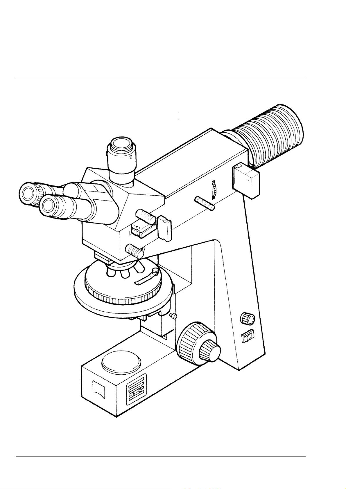
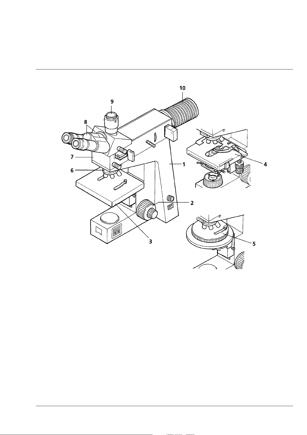
Overall View of the Axiolab A Reflected-Light Microscope
X B 40-015 e 06/99

Axiolab A Carl Zeiss
DESCRIPTION
Contents
1 DESCRIPTION................................................................................................................. 1-2
1.1 Name; Intended Application,............................................................................................1-2
1.2 Instrument Description.....................................................................................................1-2
1.3 Microscope Configurations and Modules..........................................................................1-5
1.4 Function Elements (see Fig. 1-5, after this table) .............................................................1-12
1.5 Objectives......................................................................................................................1-18
1.6 Eyepieces.......................................................................................................................1-19
1.7 Stage Micrometers and Eyepiece Reticles........................................................................ 1-20
1.8 Technical Data...............................................................................................................1-22
B 40-015 e 06/99 1-1

Carl Zeiss Axiolab A
1
1.1
DESCRIPTION
Name; Intended Application,
Manufacturer's name: Upright reflected-light microscope for routine examinations
Within the product family of upright reflected-light microscopes, the Axiolab A fits in as follows:
• Routine microscopes • Research microscopes
− Axiolab A − Axioplan 2 imaging
− Axiotech / Axiotech
vario
− Axioskop 2 / Axioskop 2
MOT
− Axiophot 2
− Axiotron 2 / Axiotron DUV
− Axioskop 2 FS / Axioskop 2 FS
MOT
The Axiolab A reflected-light microscope is a light microscope suitable for use in all areas of research and
industry involving opaque material, e.g. in
metallography (metallic and compound materials)
-
engineering mineralogy (ceramics, building materials, slags and ashes)
-
production inspection/receiving inspection (plastics, papers and textiles)
-
The Axiolab can also be equipped with a transmitted-light facility for the examination of transparent
material samples.
1.2
Instrument Description
The Axiolab A microscope is a high-performance routine microscope. Due to its compact design and
clearly arranged controls, the instrument also meets high demands on user-friendliness.
Microscope stand (1-1/1): diecast component with low-lying center of gravity and, therefore, high
-
stability.
Coaxial coarse/fine drive (1-1/2): focusing function acting on the specimen stage
-
Stage: optionally as fixed version (1-1/3), as glide stage (1-1/5) or as mechanical stage (1-1/4)
-
5-position objective nosepiece (1-1/6) with W 0.8 × 1/36" thread
-
Reflected-light illuminator H (1-1/7) with permanently attached binocular phototube A H (1-1/8), two
-
E-PL 10×/20 Br. and E-PL 10×/20 Br. foc. eyepieces , and camera port (1-1/9)
Wide-range power supply in the stand can be set to line voltages between 100 and 240 V AC
-
Reflected-light halogen illuminator (1-1/10) with 6 V, 30 W halogen lamp
-
The Axiolab A microscope features a modular design, i.e. standard modules can be easily replaced with
alternative modules, or further accessories can be added. The carrier element for this purpose is the
microscope stand (1-1/1), in which the power supply unit is also integrated. The new wide-range power
supply in the stand can be set to line voltages between 100 and 240 V AC by the user himself.
1-2 06/99 B 40-015 e
Axiolab A Carl Zeiss
Fig. 1-1 Axiolab A main modules
The specimen stage can be designed
as fixed stage (1-1/3) with stage clamps,
-
as glide stage (1-1/5) with stage clamps, 25 × 25 mm travel range, or
-
as mechanical stage (1-1/4) 75 × 35 R/A with ceramic surface and short drive.
-
Both the fixed stage and the glide stage can be locked in a top or a bottom stop. The maximum
specimen height is 45 mm.
The mechanical stage is a component of the transmitted-light version of the Axiolab A and permits the
particularly sensitive moving of transparent objects. For opaque specimens, this mechanical stage can be
equipped with a special specimen holder, permitting the maximum specimen height of 18 mm. Controls
within easy reach and the user-friendly viewing height of 440 mm with a 30° viewing angle ensure
fatigue-free work.
B 40-015 e 06/99 1-3
Carl Zeiss Axiolab A
The reflected-light halogen illuminator (1-1/10) is equipped with a 6V 30 W halogen lamp as a standard.
Its luminous intensity (lamp voltage) is continuously variable via the relevant control. The correct color
temperature for color photography (3200 K) is automatically reached in the end stop.
The XBO 75 or HBO 50 illuminators can also be attached to the Axiolab A for examinations requiring a
high illuminance. Other features: adjustable aperture diaphragm and homogeneous illumination of
object fields of up to dia. 8 mm.
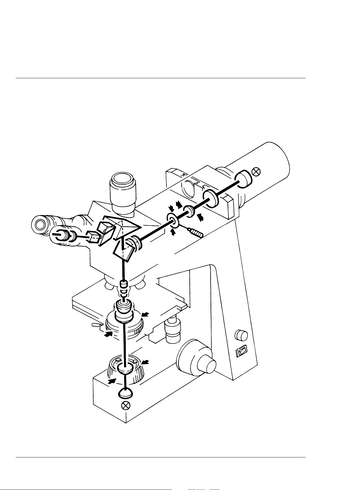
Fig. 1-2 Optical design of the Axiolab A with transmitted-light equipment
1-4 06/99 B 40-015 e

Axiolab A Carl Zeiss
The optical performance of the Axiolab A can be ideally matched to the relevant requirements by using
various objectives which are inserted into a 5-position nosepiece (1-1/6).
The camera port (1-1/9) attached to the binocular reflected-light tube (1-1/8) is available for the
documentation of microscope images. Microscope and video accessories are attached via a wide variety
of specific adapter components and modules.
Pulling out or pushing in the pushrod on the binocular tube allows you to switch between observation
and photomicrography/videomicroscopy. Switchover is 100% in each case, i.e. simultaneous observation
and documentation is not possible.
The use of specific sliders in the reflected-light illuminator H allows observation in polarization contrast.
Epi-fluorescence observation is possible with a special fluorescence configuration.
1.3
Microscope Configurations and Modules
Depending on the application, the following configurations of the Axiolab A microscope are
recommended:
- Axiolab A for reflected-light brightfield with fixed stage and Epi-objectives
Cat. No. 490960-9804-000
- Axiolab A for reflected-light brightfield with glide stage and Epi-objectives
Cat. No. 490962-9804-000
Axiolab A for reflected-light brightfield and transmitted-light examinations with mechanical stage
-
Cat. No. 490961-9804-000
B 40-015 e 06/99 1-5

Carl Zeiss Axiolab A
Fig. 1-3 Axiolab A microscope configurations
1-6 06/99 B 40-015 e
Axiolab A Carl Zeiss
Axiolab A microscope configurations Cat. No. Fixed
stage
Configurations
1
1 Microscope Axiolab A with fixed mechanical stage 490960-9804-000
2 Microscope Axiolab A with glide stage 490962-9804-000
3 Microscope Axiolab A with mechanical stage and
additional transmitted-light equipment
Selected modules for configuration 1
1.1 Microscope stand Axiolab A 450909-0000-000
1.2 Binocular phototube 30°/20 A H (100 vis/
100 doc) with reflected-light illuminator H
2.1
Eyepiece E-PL 10
2.2
Eyepiece E-PL 10
3.1
Epiplan objective 5
3.2
Epiplan objective 10
3.3
Epi objective 20
3.4
Epiplan objective 50
3.5
Achroplan objective 40
4.1 Filter slider,
is a component of binocular phototube 30°/20 A H
(100 vis/100 doc) with reflected-light illuminator H
4.2 Attenuation filter 0.06, dia. 32 467848-9001-000
5 Dust cover slider (5 pcs.)
6.1 6 V, 30 W halogen illuminator 447206-9901-000
6.2 6 V, 30 W halogen lamp 000000-0402-943
7 Dust cover G 459306-0000-000
8.1 Mains cable with European plug
8.2 Mains cable with American flat plug on request on request on request
8.3
Fuse insert T 0.8 A; 250 V; 5 × 20 mm
(not shown)
9 Accessory case
/20 Br.
×
/20 Br. foc.
×
/0.13 ∞/-
×
/0.20 ∞/-
×
/0.40 ∞/0
×
/0.70 ∞/0
×
/0.65 ∞/017
×
490961-9804-000
450962-0000-000
444231-9901-000
444232-9902-000
442920-0000-000
442930-0000-000
442941-0000-000
442950-0000-000
440050-0000-000
450962-0000-000
000000-0127-019
•
•
•
•••
•••
•••
•••
•••
•••
•••
•••
•••
•••
•••
•••
•••
•••
Glide
stage
•
••
Mechani-
cal stage
•
•
• Part of the microscope configuration
B 40-015 e 06/99 1-7
Carl Zeiss Axiolab A
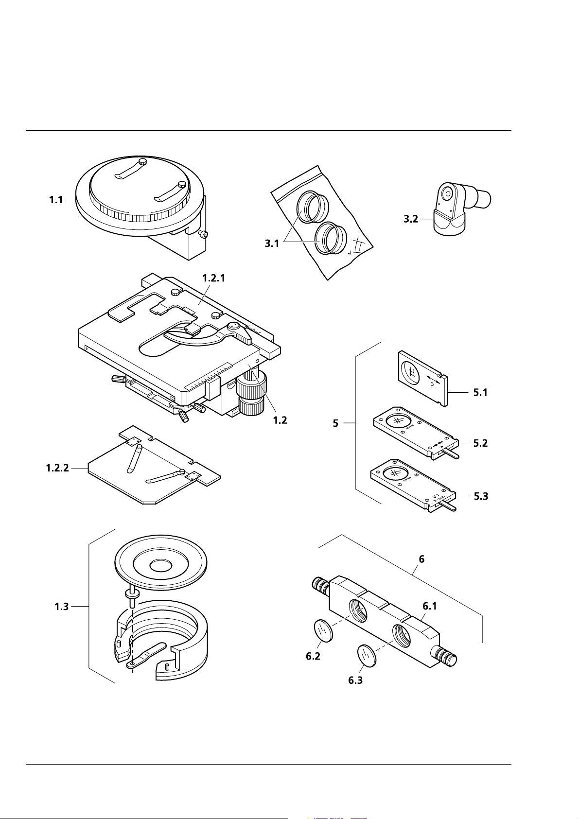
Fig. 1-4 Axiolab A accessories (1 of 2)
1-8 06/99 B 40-015 e
Axiolab A Carl Zeiss
Axiolab A accessories Cat. No. Fixed
STAGES
1.1 Glide stage with stage carrier 453509-0000-000
1.2
1.2.1 Specimen holder with spring clip R 473448-0000-000
1.2.2 Specimen holder A 433411-0000-000
1.3 Polished specimen attachment 453575-0000-000
2.1
2.2
2.2.1
2.3
2.4
2.5
2.6
2.7
2.8
2.9
2.9.1 518 N immersion oil, 20 ml oiler 444950-0000-000
3.1 Eyecup, folding 444801-0000-000
3.2
4 Stage micrometer for incident light 5+100/100y
5 Equipment for qualitative polarization in incident
5.1 Polarizer slider P 453608-0000-000
5.2 Analyzer slider A, rotary 453686-0000-000
5.3
6 Equipment for Epodye fluorescence
6.1 Filter slider FL (for dia. 25 filters) 446478-0000-000
6.2 Excitation filter BP 450 ... 490, dia. 25 447722-0000-000
6.3
Mechanical stage 75
surface and short drive, plus:
OBJECTIVES
Epiplan objective 100
Epiplan-Neofluar objective 2.5
Antiflex cap
2,5
×
Epiplan-Neofluar objective 5
Epiplan-Neofluar objective 10
Epiplan-Neofluar objective 20
Epiplan-Neofluar objective 50
for covered specimens:
Achroplan objective 20
Achroplan objective 40
Achroplan objective 100
plus:
drawing eyepiece
8
×
D = 0
light
Compensator slider λ-sub
Barrier filter LP 520, ∅ 25
35 R/A with ceramic
×
/0.75 ∞/0
×
/0.075 ∞/-, plus:
×
/0.15 ∞/-
×
/0.30 ∞/0
×
/0.50 ∞/0
×
/0.85 ∞/0
×
/0.45 ∞/0.17
×
/0.65 ∞/0.17
×
/1.25 ∞/0.17 oil
×
453517-9901-000
442980-0000-000
442310-0000-000
444922-0000-000
442320-0000-000
442330-0000-000
442340-0000-000
442350-0000-000
440040-0000-000
440050-0000-000
440080-0000-000
444128-0000-000
474027-0000-000
453706-0000-000
447737-0000-000
Glide
stage
!!!!
++
++
++
!!!!!
!!!!!
+++
!!!!!
!!!!!
!!!!!
!!!!!
!!!!!
!!!!!
!!!!!
+++
+++
+++
!!!!!
+++
+++
+++
stage
!
!!
!!
!!
!!
!!
!!
!!
!!
!!
!!!!!
!!
!!
!!
!!
!!
!!
!!
!!
!!
!!
Mechani-
cal stage
!!!!
!
!!
!
!!
!
!!
!
!!
!
!!
!!!!
!!!!
!!!!
+
!
!!
!
!!
!
!!
!
!!
!
!!
B 40-015 e 06/99 1-9
Carl Zeiss Axiolab A
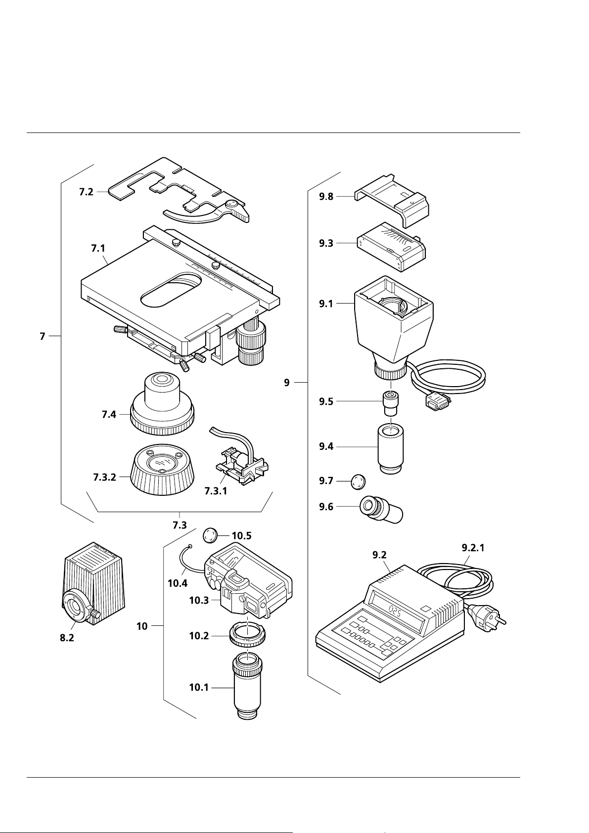
Fig. 1-4 Axiolab A accessories (2 of 2)
1-10 06/99 B 40-015 e
Axiolab A Carl Zeiss
Axiolab A accessories Cat. No. Fixed
7 Retrofit package for transmitted-light
illumination (can only be fitted by service
personnel), consisting of:
7.1
7.2 - Specimen holder (1) with spring clip R 473448-0000-000
7.3 - Transmitted-light illumination, consisting of: 450951-0000-000
7.3.1 - 6 V, 30 W halogen lamp 000000-0402-943
7.3.2 - Luminous-field diaphragm with iris
7.4 - ABBE condenser 0.9/1.25 445302-0000-000
8.1 XBO 75 (Xenon) illuminator 487202-9804-000
8.2 HBO 50 (Hg, 230 V) illuminator
9 MC 80 DX microscope camera for
9.1 MC 80 DX basic body 456031-0000-000
9.2 MC 80 DX control panel, plus: 456048-0000-000
9.2.1 Mains cable with European plug 380137-6750-000
9.3 35 mm Mot DX film cassette 456071-0000-000
9.4 Adapter 60 for microscope camera, d = 30mm 456006-0000-000
9.5
9.6
9.7
9.8 Databack D4 (for 35 mm Mot DX film cassette) 456073-0000-000
10 35-mm SLR camera
10.1
10.2 T2 adapter for CONTAX (CONTAX bayonet) 416010-0000-000
10.3 SLR-camera housing CONTAX 167 MT 416181-0000-000
10.4 Cable release 416167-0000-000
10.5
11.1 Other T2 adapters (not shown)
11.2 T2-Adapter for MINOLTA (SR bayonet) 416003-0000-000
11.3 T2-Adapter for CANON (FD bayonet) 416004-0000-000
11.4 T2-Adapter for NIKON F (F bayonet) 416009-0000-000
11.5 T2-Adapter for PENTAX (KA bayonet) 416011-0000-000
- Mechanical stage 75
surface
For enhanced incident light intensity
requirements
HBO 50 (Hg, 115 V) illuminator
36 mm, consisting of:
24
×
Projection lens P 2.5
Eyepiece E-PL 10
Photo reticle MC 2.5
CONTAX 167 MT, consisting of:
T2 2.5
Photo reticle MC 2.5
T2-Adapter for OLYMPUS OM (OM bayonet) 416002-0000-000
SLR camera adapter
×
/20 Br. foc.
×
35 R/A with ceramic
×
for MC 80/MC 80 DX
×
/d = 26 mm
×
/d = 26 mm
×
453517-9901-000
487201-9804-000
487201-9904-000
496065-9804-000
456021-0000-000
444232-9902-000
454075-0000-000
456005-0000-000
454075-0000-000
Glide
stage
!!!!!
++
++
++
++
+++
+++
!!!!!
!!!!!
!!!!!
+++
+++
+++
+++
+++
+++
+++
+++
+++
+++
+++
+++
+++
+++
+++
+++
+++
+++
+++
stage
!
!!
!!
!!
!!
!!
!!
!!
Mechani-
cal stage
!!!!
!
!!
!
!!
!
!!
!!!!
+
unit operable in combination with microscope equipment
functions in combination with a further accessory unit
B 40-015 e 06/99 1-11

Carl Zeiss Axiolab A
1.4
Function Elements (see Fig. 1-5, after this table)
Item Designation Purpose/description
1 Stand Module base of the Axiolab A microscope
2 6 V, 30 W reflected-light
halogen illuminator
3 Reflected-light illuminator H Carrier element for the binocular tube and the illuminator; also used to
4 Camera port Enables (after removal of the dust cap) the connection of various
5 Binocular tube Binocular viewing tube permanently attached to the reflected-light
6, 7 Eyepiece, right and left Fixed and adjustable (foc) eyepiece; the fixed eyepiece must be
8 Dust protection slider
(2 pcs.)
9 Objective nosepiece Carrier for the maximum of 5 objectives which are swung into the
10 Specimen stage, fixed
11 Coaxial coarse and fine drive, L Permits the specimen stage to be lifted and lowered within a travel
Reflected-light illuminator with 6 V, 30 W halogen lamp
accommodate various technique sliders
adapters for attachment of photomicrography/videomicroscopy
equipment (35 mm cameras, video cameras)
illuminator H; can be set to the user's individual interpupillary distance;
after removal of the dust caps, dia. 30 mm eyepieces - one of which is
adjustable (foc) - can be inserted.
assigned to the less myopic eye; two focusing eyepieces are required if
reticles or photo reticles are used.
These two dust protection sliders should always remain in the
Axiolab A microscope; technique sliders can also be inserted only if
transmitted-light equipment is available
beam path manually
Stage area: 160
- 20 mm (stage attached at upper stop) or
- 45 mm (stage attached at lower stop)
Two spring clips (supplied) enable specimens attached to a 26
slide to be held in position (also see item 31)
range of approx. 20 mm (also see section 1. 6 (7));
used for specimen focusing; mechanical unit together with item 29
140 mm; for the maximum specimen height of
×
76 mm
×
12 Connecting cable for 6 V
30 W reflected-light illuminator
13 ”A/D” illumination converter Permits the switchover between incident light and transmitted-light
Must be connected to the sockets at the instrument rear to allow
operation of the reflected-light illuminator
when instruments with an additional transmitted-light equipment are
used.
1-12 06/99 B 40-015 e

Axiolab A Carl Zeiss
Item Designation Purpose/description
14 Fuse holder Holder for two fuse inserts
15 Fuse insert
17 Mains cable To apply the supply voltage
18 Pushrod Pushrod to change the beam path between
19 Aperture diaphragm Used to limit the illumination aperture; can be changed via knurled
20 Filter slider Permits the insertion of dia. 32 filters in the illumination beam path; can
21 Pushrod for luminous-field
diaphragm (incident light)
22 Dust protection slider Prevents the entry of dust. Can be replaced during operation with the
23 Polarization slider P Permits observation of the specimen in polarized light (EAST-WEST
24 Dust protection slider
(2 pcs.)
T 0.8 A; 250 V; 5 × 20 mm
- observation through the binocular tube (pushrod pushed in)
- photomicrography/videomicroscopy through camera port
(pushrod pulled out)
wheel
be equipped, for example, with
- attenuation filter D = 0.06
Permits insertion of a perforated plate with 1/3 field size
polarization slider P (item 23)
oscillation direction)
Prevents the entry of dust. Can be replaced during operation with the
analyzer slider A and the λ-sub compensator slider
25 Analyzer slider A,
rotary
26 Compensator slider
-sub
λ
Enables polarization contrast in combination with the polarizer slider P
(NORTH-SOUTH oscillation direction with ±10° fine adjustment
possibility)
In combination with the polarizer and analyzer slider, this slider permits
the color contrast of anisotropic specimen details
B 40-015 e 06/99 1-13
Carl Zeiss Axiolab A
Item Designation Purpose/description
27 ”Luminous intensity” control Continuous control of the illuminance of the light source by changing
the lamp voltage in the range from > 1.5...6 V.
At 6 V (right stop) the 3200 K color temperature for color photography
is reached.
28 On/off switch with mains pilot
Main instrument switch to switch the line voltage on and off
lamp
29 Coaxial coarse and fine drive, R Permits the specimen stage to be lifted and lowered within a travel
range of approx. 20 mm (also see section 1. 6 (7));
used for specimen focusing; mechanical unit together with item 11
30 Ventilation grille For ventilation of the transmitted-light illuminator, if contained in the
instrument configuration
31 Glide stage The glide stage features a manually adjustable stage plate with a travel
range of 25
25 mm. The max. specimen height corresponds to that
×
of the fixed stage.
Two supplied spring clips enable objects on a 26
76 mm slide to be
×
held in position.
Objects can also be held in position by the so-called polished specimen
stage (accessory), with which unilaterally polished specimens can be
aligned plane-parallel with the stage surface.
32 Condenser drive *) To focus the condenser in the work position
33 Specimen holder with spring
To mount and guide transmitted-light specimens
clip R *)
34 Specimen holder A To mount and guide opaque objects or specimens
35 Condenser *) Brightfield condenser 0.9/1.25 or other condenser included in the list
36 Luminous-field diaphragm *)
Adjustable iris diaphragm to change the field size in transmitted-light
(transmitted-light)
37 Clamping screw *) To clamp the condenser
38 Centering screw *) To center the image of the luminous-field diaphragm
39
Mechanical stage 75
*)
35 R/A
×
Sensitive mechanical stage with ceramic surface, short drive, and a
travel range of 75
35 mm
×
40 Pushrod Pushrod to change the beam path between reflected-light and
transmitted-light observation;
pushrod pulled out reflected-light observation
-
pushrod pushed in transmitted-light observation
-
*) Part of the transmitted-light configuration
1-14 06/99 B 40-015 e

Axiolab A Carl Zeiss
1Stand
2 6 V, 30 W halogen illuminator
3 Reflected-light illuminator H
4 Camera port
5 Binocular tube
6 Eyepiece, fixed
7 Focusing eyepiece
8 Dust protection slider
9 5-position objective nosepiece
10 Specimen stage, fixed
11 Coaxial coarse and fine drive (left, also see item 29)
12 Connecting cable for halogen illuminator
13 ”A/D” illumination converter
14 Fuse holder
15 Fuse inserts (T 0.8 A; 250 V; 5 × 20 mm)
17 Mains cable
18 Pushrod to change beam path
19 Aperture diaphragm
20 Filter slider
21 Pushrod (for luminous-field diaphragm)
22 dust protection slider
23 Polarizer slider P
24 Dust protection slider
25 Analyzer slider A, rotary
26
27 ”Light intensity” control
28 ON/of switch with mains pilot lamp
29 Coaxial coarse and fine drive (right, also see item 11)
30 Ventilation grille
31 Glide stage
32 Condenser drive
33 Specimen holder with spring clip R
34 Specimen holder A
35 Condenser
36 Luminous-field diaphragm (transmitted-light)
37 Clamping screw
38 Centering screw
39 Mechanical stage
40 Pushrod to change between reflected-light or transmitted-light observation
-sub compensator slider
λ
B 40-015 e 06/99 1-15

Carl Zeiss Axiolab A
Fig. 1-5 Axiolab A function elements (1 of 2)
1-16 06/99 B 40-015 e

Axiolab A Carl Zeiss
2
1
Fig. 1-5 Axiolab A function elements (2 of 2)
1
B 40-015 e 06/99 1-17

Carl Zeiss Axiolab A
1.5
Objectives
The objectives are the optical centerpiece of the microscope. The following is an example of how
objectives can be labelled:
Epiplan 10×/0.20 ∞/-
where
10× : objective magnification, with a defined color ring on the objective being allocated to each
magnification step (Carl Zeiss color ring code)
0.20 : numerical aperture
∞ : infinite tube length
- : can be used with cover slip thickness D = 0 or 0.17 mm
or
0 : can only be used without cover slip, that means D = 0
0.17 : can be used with cover slip thickness D = 0.17 mm
and
Oil : oil immersion objective
Ph 2 : phase contrast objective with a green color ring and phase stop Ph 2
Color ring code for objective magnification
Color ring on
objective
Magnification
factor
black brown red orange yellow green light
blue
1.25× 2.5× 4×; 5× 6.3× 10× 16×;20×;
40×; 50× 63× 100×;
25×;32×
dark
blue
white
150×
The objective magnification multiplied with the eyepiece magnification (usually 10×) results in the visual
overall magnification: e.g. 10 × 10 = 100×.
The numerical aperture × 1000, e.g. 0.20 × 1000 = 200×, is the highest useful magnification, i.e. no
further details are resolved above that limit.
In transmitted-light applications, the exact observance of the cover slip thickness of 0.17 mm is all the
more necessary the higher the numeric aperture of the objective. Therefore, so-called "Korr" objectives
can be set for different cover slip thicknesses via a correction ring. For this, a specimen area is searched,
and the position of the correction ring where optimum focus and image contrast are obtained is
determined (refocusing is always required).
Immersion objectives are always insensitive to differences in cover slip thickness.
When immersion objectives are used, the air between the cover slip and the objective is replaced with a
liquid, which is immersion oil in most cases. The plastic oiler containing 20 ml of 581 N immersion oil is
particularly suitable for this purpose.
1-18 06/99 B 40-015 e

Axiolab A Carl Zeiss
The following objectives are available for the Axiolab A:
Microscopy
technique
Reflected-light
brightfield
Reflected-light
brightfield
Transmitted-light
brightfield
Objective Magnification/
Num. Aperture
Epiplan
Epiplan
Epiplan
Epiplan
Epiplan
Epiplan
Epiplan-Neofluar
Epiplan-Neofluar
Epiplan-Neofluar
Epiplan-Neofluar
Epiplan-Neofluar
Epiplan-Neofluar
Achroplan
Achroplan
Achroplan
Achroplan
Achroplan
Achroplan
Achroplan
Achroplan
5
×
10
20
50
100
2.5
5
×
10
20
50
20
40
50
63
63
100
100
Iris
/0.13
×
×
×
×
/0.15
×
×
×
×
×
×
×
×
/0.20
/0.40
/0.70
/0.75
×
/0.075
/0.30
/0.50
/0.80
/0.45
/0.65
/0.90 Oil
/0.80
/0.95
/1.25 Oil
×
/1.25 Oil
×
Free working
distance
in mm
19.8 - 442920-0000-000
18.4 - 442930-0000-000
0.6 0 442941-0000-000
0.95 0 442950-0000-000
0.95 0 442980-0000-000
9.4 - 442310-0000-000
13.7 - 442320-0000-000
5.7 0 442330-0000-000
1.4 0 442340-0000-000
0.58 0 442350-0000-000
2.07 0.17 440040-0000-000
0.59 0.17 440050-0000-000
0.29 0.17 440057-0000-000
0.29 0.17 440060-0000-000
0.15 0 440068-0000-000
0.19 0.17 440080-0000-000
0.19 0.17 440086-0000-000
Cover slip
thickness
D in mm
Cat. No.
1.6
Eyepieces
The following eyepieces are available for the Axiolab A:
Eyepiece Image angle Cat. No.
Eyepiece E-PL 10×/20 Br.
Eyepiece E-PL 10×/20 Br. foc.
Eyepiece PL 16×/16 Br.
Eyepiece PL 16×/16 Br. foc.
43° 444231-9901-000
43° 444232-9902-000
54° 444053-0000-000
54° 444054-0000-000
If required, eyecups for the eyepieces can be ordered under Cat. No. 444801-0000-000.
B 40-015 e 06/99 1-19

Carl Zeiss Axiolab A
1.7
Measuring and counting using the microscope requires stage micrometers and eyepiece reticles, a small
selection of which is listed below:
Illustration Description, Technical data Cat. No.
Stage Micrometers and Eyepiece Reticles
stage micrometer, positive 5 + 100/100 y
D = 0.17 mm
gradation on the +y-axis: 5 mm in 5 intervals
gradation on the -y-axis: 1 mm in 100/100 mm =
10 µm, accuracy ±1µm
crossline micrometer 14 : 140 / d = 26 mm
gradation length = 14 mm
increments = 0.1 mm
gradation tolerance ≤ 0.001 mm
eyepiece reticle / d = 26 mm 474064-0000-
474026-0000000
454060-0000000
000
crossline micrometer 10 : 100 / d = 26 mm
gradation length = 10 mm
increments = 0.1 mm
gradation tolerance ≤ 0.001 mm
1-20 06/99 B 40-015 e
474066-9901000

Axiolab A Carl Zeiss
☞
net micrometer 12.5 ×××× 12.5 / 5 ; 10,
d = 26 mm
area 12.5 × 12.5 mm, divided in fields of
10 × 10
photo reticle MC 2.5×××× / d = 26 mm
for 35 mm photography with an additional
magnification of 2.5×××× or for large-format
photography with 10×××× additional magnification.
If an eyepiece reticle is used, the binocular tube or the phototube must be equipped with two
foc. eyepieces containing an adjustable eyelens, into one of which the eyepiece reticle is
mounted.
474068-0000000
454075-0000000
B 40-015 e 06/99 1-21

Carl Zeiss Axiolab A
1.8
Technical Data
Dimensions and weight
Dimensions (width × depth × height) ......................................................................180 × 400 × 430 mm
Footprint (recommended with mat)...................................................................................440 × 310 mm
Weight.............................................................................................................................. approx. 10 kg
Ambient conditions for
storage and transport (in packaging)
Permissible ambient temperature ....................................................................................... -40 to +50 °C
Permissible relative humidity ...................................................................................................max. 85 %
Atmospheric pressure ............................................................................................. 800 hPa to 1060 hPa
Operation
Permissible ambient temperature ........................................................................................ +5 to +40 °C
Permissible relative humidity ...................................................................................................max. 85 %
Altitude.............................................................................................................................. max. 2000 m
Atmospheric pressure ............................................................................................. 800 hPa to 1060 hPa
Pollution degree ................................................................................................................................... 2
Operating data
Category of use.................................................................................................................. closed rooms
Protection class.......................................................................................................................................I
Protection type................................................................................................................................IP 20
Electrical safety.................................................................in compliance with DIN EN 61010 (IEC 1010-1)
including CSA and UL directives
Excess voltage category .........................................................................................................................II
Radio interference suppression....................................................... in accordance with EN 55011, Class B
Insensitivity to noise.................................................................................... in accordance with EN 50082
Line voltage....................................................................................................... 100 to 240 V AC ±10 %
....................................................................................................Change of line voltage is not required!
Line frequency...................................................................................................................... 50 to 60 Hz
Power consumption...............................................................................................................max. 80 VA
Fuses
for all line voltages above mentioned............................................................. T 0.8 A; 250 V; 5 × 20 mm
1-22 06/99 B 40-015 e

Axiolab A Carl Zeiss
Mechanical data of specimen stages
Stage models............................................................................. fixed stage/glide stage/mechanical stage
Maximum specimen height:
stage at bottom stop (not possible for mechanical stage)................................................... 45 mm
stage at top stop .............................................................................................................. 20 mm
Light source
6 V, 30 W halogen illuminator:
halogen lamp with square flat-core filament ..............................................HLW S 5-A, 6 V, 30 W
lamp voltage (variable).................................................................................... >1.5 V to max. 6 V
power .................................................................................................................................30 W
color temperature at end stop ..........................................................................................3200 K
light flux at 6 V................................................................................................................. 510 lm
average life at 6 V/4.8 V ......................................................................................... 300 h/2000 h
illuminated area...................................................................................................... 1.7 × 1.7 mm
Opto-mechanical data
Stage focusing.................................................................................................... coaxial coarse/fine drive
lifting range: 20 mm
coarse drive: 1 rotation = 4 mm
fine drive: 1:10 step-down ratio
Objective change ................................................................................. manually via 5-position nosepiece
Maximum field of view ................................................................................................................ 20 mm
Maximum object field .................................................................................................................... 8 mm
Binocular 30°/20 H reflected-light tube with camera/TV port:
maximum field number............................................................................................................20
interpupillary distance.................................................................variable between 55 and 75 mm
viewing angle.........................................................................................................................30°
viewing height................................................................................................................ 440 mm
observation and camera/video port ........................................................................ tube factor 1×
observation and camera/video port ........................................................ 100%/0% or 0%/100%
camera/video port ..............................................................................................60 mm interface
Eyepieces................................................................................... E-PL 10×/20 Br. and E-PL 10×/20 Br. foc.
plug-in diameter............................................................................................................... 30 mm
B 40-015 e 06/99 1-23

Carl Zeiss Axiolab A
1-24 06/99 B 40-015 e

Axiolab A Carl Zeiss
START-UP
Contents
2 Start-Up.........................................................................................................................2-3
2.1 Unpacking the Instrument................................................................................................2-3
2.2 Screw in Objectives..........................................................................................................2-3
2.3 Insertion of Eyepieces ......................................................................................................2-4
2.3.1 Insertion of Eyepiece Reticle.............................................................................................2-4
2.3.2 Compensation of Ametropia when Eyepiece Reticles are used........................................... 2-5
2.4 Setting of Interpupillary Distance......................................................................................2-5
2.5 Attachment of Reflected-Light Halogen Illuminator...........................................................2-6
2.6 Retrofit the Transmitted-Light Halogen Illumination ..........................................................2-6
2.6.1 Switch on the Transmitted-Light Halogen Illuminator........................................................2-7
2.7 Equipment of Filter Slider.................................................................................................2-7
2.8 Set the Luminous-Field Diaphragm...................................................................................2-8
2.9 Connecting the Instrument to the Line............................................................................. 2-8
B 40-015 e 06/99 2-1

Carl Zeiss Axiolab A
2-2 B 40-015 e 06/99

Axiolab A Carl Zeiss
2
The three versions of the Axiolab A reflected-light microscope, including accessories, are supplied in
standard packaging. We would recommend you to keep the transport cases for storage or return of the
instrument to the manufacturer.
2.1
• Remove the microscope from the transport case
and place it on the mat (2-1/1) provided on the
worktable.
• Remove the plastic sleeve (2-1/4) from the
instrument.
• Remove the adhesive strips which secure the
various controls during transport.
• Leave dust protection and technique sliders
(2-1/2, 5, 6) inserted in the reflected-light
illuminator H (2-1/3) in the instrument.
START-UP
Unpacking the Instrument
2.2
• Remove the dust caps (2-2/2) according to the
number of objectives and screw the objectives
into the nosepiece (2-2/1) clockwise one by
one, starting with the lowest magnification
(2-2/3).
☞
Screw in Objectives
The dust caps should remain on those
nosepiece eyes which are not required.
Fig. 2-1 Unpacking the instrument
Fig. 2-2 Screw in objectives
B 40-015 e 06/99 2-3

Carl Zeiss Axiolab A
2.3
• Remove both protection caps from the binocular tube.
• Insert the fixed eyepiece, e.g. E-PL 10×/20 Br., in one tube and the focusing eyepiece E-PL 10×/20 Br.
foc. in the other tube.
Insertion of Eyepieces
The focusing eyepiece is used to compensate for ametropia of the user's eyes.
☞
2.3.1
Insertion of Eyepiece Reticle
The E-PL 10×/20 Br. foc. eyepieces are intended
for use with eyepiece reticles (see overview under
1.6).
Fig. 2-3 Insertion of eyepiece reticle
If eyepiece reticles are inserted into the unscrewed mount by the customer, attention must be
☞
paid to the labelling being visible the right way up after insertion.
The slight image shift caused by the additional
path through the glass is taken into account on
the diopter scale by the fact that the zero point
position is indicated not by the white dot (2-3/W)
but by the red dot (2-3/R).
The eyepiece reticles (2-3/1) have been adhered to
screw-in mounts (2-3/2) to allow easy
replacement.
• To replace a reticle, unscrew the screw-on
mount containing the eyepiece reticle and
replace it with the required one.
2-4 B 40-015 e 06/99

Axiolab A Carl Zeiss
2.3.2
The correct use of an eyepiece reticle requires two focusing eyepieces, e.g. PL 10×/20 Br. foc., to enable
compensation of ametropia.
• Use the eyelens of the focusing eyepiece to focus on the line figure of the eyepiece reticle; focus on
the edge of the field of view if no eyepiece reticle is used.
• Focus on the microscope image of a specimen via the focusing drive by looking through the eyepiece
with reticle.
• When the image and the eyepiece reticle are in focus in the above eyepiece, focus the image for the
second eye via the focusing eyelens of the second eyepiece.
Compensation of Ametropia when Eyepiece Reticles are used
The position of the focusing drive on the stand must not be changed.
☞
2.4
• The eyepiece distance is matched to the individual interpupillary distance by swinging the eyepiece
tubes symmetrically towards one another. The eyepiece distance can be set in the range between 55
and 75 mm, and you should try to remember the individual value once set.
Setting of Interpupillary Distance
B 40-015 e 06/99 2-5

Carl Zeiss Axiolab A
2.5
• Attach dovetail guide (2-4/3) of 6 V, 30 W
☞
• Connect cable (2-4/5) to the two sockets on the
Attachment of Reflected-Light Halogen Illuminator
halogen lamp (2-4/4) to the microscope stand
and tighten hexagonal screw (2-4/2) using the
SW 3 screwdriver (2-4/1).
The halogen lamp must be mounted
to the stand in a vertical position, also
see Fig. 3-2.
For visual control, remove lamp cover
(2-4/4) by slightly turning it to the left.
instrument rear.
2.6
Transmitted-light observation with the Axiolab A is
possible with the configuration described in
Fig. 2-4 Attachment of reflected-light
halogen illuminator
The transmitted-light illumination equipment can be subsequently mounted to the Axiolab A
☞
The transmitted-light illumination package consists of:
- mechanical stage 75 × 35 R/A with ceramic surface and short drive,
- specimen holder with spring clip R,
- transmitted-light illuminator, containing halogen lamp with mount and luminous-field diaphragm with
iris,
- ABBE condenser 0.9/1.25 or ABBE condenser 0.9/1.25 with 5-position turret disk
only by Carl Zeiss service personnel.
section 1.3. The pure reflected-light versions of the
Axiolab A can also be upgraded for transmittedlight observation by installing the ”Retrofit
package for transmitted light” (1-4/7).
Retrofit the Transmitted-Light Halogen Illumination
2-6 B 40-015 e 06/99

Axiolab A Carl Zeiss
2.6.1
☞
To change to transmitted-light operation, press the A/D converter (1-5/13) at the rear of the Axiolab A
into the lower position.
The functions of the on/off switch (1-5/28) and the "illuminance" control (1-5/27) are retained,
regardless of the position of the AD converter A/D (1-5/13) (see section 1.5).
Switch on the Transmitted-Light Halogen Illuminator
Normally, the position of the A/D illumination converter (1-5/13 or 2-7/4) is of no importance
with the Axiolab A.
Only if the transmitted-light illumination is a standard feature or has been subsequently
installed, the A/D converter will have the following functions:
• the power supply for the reflected-light halogen illuminator is switched on in the upper,
pressed position of the converter.
• in the lower, pressed position of the converter, the power supply for the transmitted-light
illuminator is switched on.
2.7
• Equip filter slider (2-5/3) with the filters (2-5/2)
required for the relevant microscopy technique,
e.g. with
− neutral-density filter N 0.06
− neutral-density filter N 0.25
− conversion filter 3200...5500 K for use of
− narrow-band interference filter, e.g. for
Insert equipped filter slider in the compartment
until it click-stops in the relevant position in the
reflected-light illuminator (2-5/1).
Equipment of Filter Slider
(6% transmission)
(25% transmission)
daylight color film
contrast enhancement
The filter diameter is 32 mm.
☞
Fig. 2-5 Equipment of filter slider
B 40-015 e 06/99 2-7

Carl Zeiss Axiolab A
Fig. 2-6 Setting the luminous-field
diaphragm
2.8
• The pushrod (2-6/1) for the luminous-field
diaphragm has two positions:
− pushed in: the full field of view is visible
− pulled out: the visible field of view is reduced
2.9
Set the Luminous-Field Diaphragm
without restriction.
to approx. 1/3 of the overall diameter. This
can be useful as an aid to find the object
plane, i.e. the visible diaphragm is focused.
Furthermore, this restriction of the field of
view enables reduction of the false light
portion of weakly reflecting reflected-light
specimens.
Connecting the Instrument to the Line
Fig. 2-7 Connecting the instrument to the
line
The microscope can be operated using line
voltages of 100 − 240 V without conversion
• Connect the line cable (2-7/1) with connector
to the instrument socket (2-7/3) and connect
the earth-contact plug to the line.
• Switch on the instrument via the on/off switch
(2-7/2) on the left-hand side of the instrument.
• The green LED integrated into the on/off
switch lights up to indicate that the machine is
ready for operation (switch in „I“ position).
The integrated halogen lamp 6 V, 30 W must
also be on.
The change of fuses is described in
☞
section 4.2.
2-8 B 40-015 e 06/99

Axiolab A Carl Zeiss
OPERATION
Contents
3 Operation......................................................................................................................3-3
3.1 Switch on the Instrument.................................................................................................3-3
3.2 Illumination and Contrasting Techniques ..........................................................................3-4
3.2.1 Setting of Reflected-Light Brightfield ................................................................................3-4
3.2.2 Setting of Reflected-Light Polarization ..............................................................................3-5
3.2.3 Setting of Transmitted-Light Polarization with extended Polarization Equipment................ 3-5
3.2.4 Setting of Epi-Fluorescence ............................................................................................ 3-13
3.2.5 Setting of Transmitted-Light Brightfield (KÖHLER Illumination) ........................................3-14
3.3 Attachment of Microscope Stages and Specimen Holders............................................... 3-15
3.3.1 Attachment of Pol Rotary Stage ..................................................................................... 3-16
3.4 Use of Polished Section Attachment............................................................................... 3-17
3.5 Photomicrography and Videomicroscopy........................................................................ 3-18
3.5.1 Attachment of Photomicrography Equipment.................................................................3-19
3.5.2 Attachment of Adapters for Video Cameras...................................................................3-22
3.6 Insertion of 8× Drawing Eyepiece ...................................................................................3-24
B 40-015 e 06/99 3-1

Carl Zeiss Axiolab A
3-2 B 40-015 e 06/99

Axiolab A Carl Zeiss
3
3.1
• Switch on the instrument via the on/off switch
(3-1/6).
− The green line control lamp in the switch (3-
− The halogen lamp 6 V, 30 W in the
☞
• Set the required image brightness via the
illuminance control (3-1/5).
OPERATION
Switch on the Instrument
1/6) must light up.
reflected-light illuminator (3-1/2) must light
up.
The “I” is visible when the on/off
switch is switched on and the "0" is
visible when the on/off switch is
switched off.
Fig. 3-1 Switch on the instrument
• Depending on what is required, insert
attenuation or conversion filter in the filter
slider (3-1/3) and push the slider in the beam
path (also see section 2.7).
• Swing required objective (3-1/7) in the beam
path; make sure to operate the nosepiece only
via the knurled ring.
For observation, the pushrod (3-1/4) must be pushed in. In this position, 100 % of the light of
☞
the beam path is directed to the observation port of the binocular tube (3-1/1).
B 40-015 e 06/99 3-3

Carl Zeiss Axiolab A
3.2
The description of the illumination and contrasting techniques is based on the following microscope
settings:
• The Axiolab A microscope is ready for operation as described in chapter 2 and switched on as
described in section 3.1.
• The pushrod (3-2/3) has been pushed in to direct 100% of the light to the observation port of the
binocular tube.
3.2.1
Fig. 3-2 Setting of reflected-light brightfield
Illumination and Contrasting Techniques
Setting of Reflected-Light Brightfield
23
1
1
4
5
6
7
10
8
9
• Place a specimen of as much contrast as
possible (3-2/6) on the specimen stage (3-2/10);
if required by the specimen height, lower the
specimen stage via the coarse drive (3-2/9) or
secure it in the lower stop position.
• Pull out plane glass pushrod (3-2/2).
• Look through the binocular tube (3-2/1) and set
the eyepiece distance and interpupillary
distance again as required (also see section 2.4).
• The aperture diaphragm (3-2/4) must be set to
approx. half the size of the opening diameter
by turning the adjustment wheel downwards.
• Pull out pushrod for luminous-field diaphragm
(3-2/5) until stop.
• Use the coarse/fine drive (3-2/9, 8) focus the
circular luminous-field diaphragm now visible in
the field of view.
• Insert the pushrod for the luminous-field
diaphragm (3-2/5) again; the entire field of view
is now visible.
• Refocusing on the specimen can be performed via the fine drive (3-2/8).
• Use the illuminance control (3-2/7) to set the brightness in the field of view to a value agreeable to
your eyes.
Depending on the specimen, the contrast is now adjusted via the aperture diaphragm (3-2/4).
☞
3-4 B 40-015 e 06/99
However, the aperture diaphragm cannot be used to control the image brightness (loss in
image resolution).

Axiolab A Carl Zeiss
3.2.2
The Axiolab A microscope is ready for operation as
described in chapter 2, and switched on as
described in section 3.1.
• Pull out the plane glass pushrod (3-3/1).
• Pull out the dust protection sliders (3-3/2+6)
from the reflected-light illuminator H.
• Push polarization slider P (3-3/3) into the slider
mount (vertical slot) from the right.
• Push rotary analyzer slider A (3-3/4) in the upper
horizontal slider mount.
Setting of Reflected-Light Polarization
☞
• Set the analyzer slider to optimum contrast
(maximum dimming) in the field of view via the
adjustment lever.
For reasons of intensity, no filters
should be contained in the beam path.
Fig. 3-3 Setting of reflected-light polarization
If possible, this analyzer position should not be changed.
☞
• Reduce illumination aperture by turning the adjusting wheel (3-2/4) of the aperture diaphragm
downwards.
• To enhance the color contrast of anisotropic object details, the λ-sub compensator slider (3-3/5) can
be inserted in the lower horizontal slider mount.
The color intensity can then be varied via the lever on the λ-sub compensator slider.
3.2.3
Setting of Transmitted-Light Polarization with extended Polarization Equipment
The optional, extended polarization equipment includes the following items:
rotary Pol stage (3-4/3)
-
Pol object guide (3-4/4)
-
swing-in polarizer D (3-4/5)
-
B 40-015 e 06/99 3-5

Carl Zeiss Axiolab A
(1) Centering of Objectives (only for Axiolab Pol catalogue No. 450910-0000-000)
Fig. 3-4 Centering of objectives
When the Pol stage (3-4/3) and uncentered objectives are turned, object details above the center of the
eyepiece cross migrate to circular paths (3-4/1 - dashed line). The following procedure is required to
center the objectives:
• Unlock the stage stop by turning screw (3-4/6) by approx. ¼ rotation in counterclockwise direction.
• Swing in transmitted-light objective of medium magnification (20× - 50×) via the nosepiece.
• Insert SW 1.5 key (3-4/2) in the drilled centering holes on the nosepiece.
• Turn the specimen stage and search for the apparent center of rotation (cross (3-4/1)). The center of
rotation is also the center of the stage rotation.
• Use the keys to move this center of rotation to the intersecting point of the eyepiece crosslines and
therefore into the optical axis of the microscope.
• Repeat the procedure with a distinct, small object detail in the direct proximity of the center of the
rotary stage.
• Carefully remove the key.
• Swing in the neighboring objective; search for the center of rotation and the distinct object details
and perform the adjustment procedure as described above.
To retain the centering status, it is absolutely necessary to change the objectives only via the
☞
knurled ring of the objective nosepiece.
3-6 B 40-015 e 06/99

Axiolab A Carl Zeiss
(2) Transmitted-Light Polarization - Detection of Birefringence
This technique is used for the examination of transparent, birefringent objects. Birefringence can be
recognized, with crossed polarizer and analyzer, by the otherwise dark field of view being brightened 4
times when the specimen stage is rotated about 360°. Respective of birefringence, thickness and
orientation of the object, the interference colors range from just visible gray (e.g. in biological objects) to
white, yellow, red, blue, etc. and high-order white.
• Set the microscope as usual for brightfield
examinations in transmitted light.
• Push in the plane glass pushrod (3-5/3).
• Swing in polarizer (3-5/6) and set it to 0°.
• Push in analyzer (3-5/1) until stop so that the
field of view is dark.
When a ± 5° rotary analyzer is used,
☞
the analyzer must be in the center
stop position.
• Move the object into the field of view and turn
the stage (3-5/4) containing the object.
Birefringence is indicated by the either
☞
colorless or colored brightening of the
object. However, optically anisotropic
materials can also remain dark if an
isotropic direction, e.g. of optically
uniaxial or biaxial crystals is oriented
parallel to the observation direction.
The conoscopic viewing method
makes it possible to find out whether
the object is isotropic or anisotropic.
Fig. 3-5 Setting of transmitted-light
polarization
B 40-015 e 06/99 3-7

Carl Zeiss Axiolab A
(3) Transmitted-Light Polarization - Determination of the n
γγγγ
Vibration Direction and
'
Determination of the Path Difference
γ
150 700 -400
Fig. 3-6 Determine the n
γ
γ
λ
vibration direction using the example of an artificial fiber
γγγγ
'
γ
γ
λ
Application
The position of the two directions with the relatively highest (n
index, or the absolutely highest (n
) and the absolutely lowest (nα) refractive index, in relation to
γ
) and the relatively lowest (n
γ
'
) refractive
α
'
morphological directions of crystal surfaces, crystal needles or fibers, is an important criterion for
recognition. It is also used, for example, for the diagnosis of biocrystals (gout, pseudogout).
Settings
Fig. 3-7 Schematic diagram of the color
chart in addition and subtraction
position
• Set the microscope as usual for transmitted-
light brightfield examinations.
• Turn stage until the first stop position, unlock
stop and turn the stage until the object features
maximum darkness.
• Activate stage stop mechanism and turn stage
around 45° until the next stop so that the
longitudinal axis of the fiber is oriented in NESW direction.
• Allocate a path difference of approx. 150 nm to
this color on the MICHEL LEVY color chart.
− When the λ-compensator (3-5/2) has been
pushed in, the color of the fiber changes to
yellow-orange (path difference approx. 400
nm).
− When the stage is turned around 90°, the
fiber appears greenish blue (path difference
approx. 700 nm).
3-8 B 40-015 e 06/99

Axiolab A Carl Zeiss
Conclusions
The n
-direction of the λ-compensator is NE-SW oriented. The environment of the fiber exhibits a dark,
γ
first-order red (path difference is one λ; approx. 550 nm). The fiber itself appears greenish blue (path
difference approx. 700 nm). The higher interference color (700 nm) can only have been created by
addition of the path differences of the object (approx. 150 nm) and that of the λ-compensator (approx.
550 nm), while the lower one (approx. 400 nm) must have been created by subtraction.
Addition is possible if n
of the compensator and n
γ
of the object are parallel. Therefore, n
γ
'
of the object
γ
'
also lies in NE-SW direction in the case of a higher interference color and is oriented parallel to the
longitudinal axis of the fiber.
Summary
Compare the interference colors (path differences) in the two diagonal positions. The higher path
difference results if both n
-directions are parallel, which defines the n
γ
-direction of the object.
γ
'
If the thickness of the specimen is known or can be measured, the MICHEL LEVY color chart
☞
can be used to determine the birefringence ∆n
of minerals, synthetic crystals, polymers,
γ
strained glass, biocrystals or erythrocytes; starting at the intersection point of the Γ-value and
of the thickness d, the inclined line is followed to the outside right up to the edge of the chart.
B 40-015 e 06/99 3-9

Carl Zeiss Axiolab A
(4) Transmitted-Light Polarization - Determination of the Optical Character of Crystals
Application
The optical character of transparent and weakly absorbing crystals must be determined for the diagnosis
of crystals. The determination is made in conoscopic observation. The main field of application is classical
petrography. However, it is also possible to identify and characterize synthetic crystals, industry minerals
and plastics (e.g. films).
Settings
• Set the microscope as usual for brightfield and polarization examinations in transmitted light (see Fig.
3-5).
• Swing in low-power objective.
− In conoscopic observation, those crystals (e.g. of a mineral section) are optimally oriented which
alter the brightness least during the stage rotation. In that case, the optical axis of uniaxial crystals
or one of the optical axes of biaxial crystals is almost parallel to the observation direction.
• Move one such crystal into the center of the switchable crosslines. Then swing in the objective with
the highest dry aperture and the condenser front lens.
• Check whether the condenser stop is fully open and lift the condenser until the image of the
luminous-field diaphragm is in focus.
• Now close the field of view diaphragm until the grain borders of the selected crystal are no longer
visible. This avoids the axis image of the examined crystal being overlaid by axis images of neighboring
crystals. Object details up to dia. 10 µm can thus be faded out.
When the stage is turned, the object must be oriented to the center of the crosslines, i.e. it must
remain within the examination area.
• Replace one eyepiece with the diopter pinhole or the auxiliary lens.
• Focus the axis image (pupil image).
− The set conoscopic image shows whether the crystal is uniaxial or biaxial.
3-10 B 40-015 e 06/99
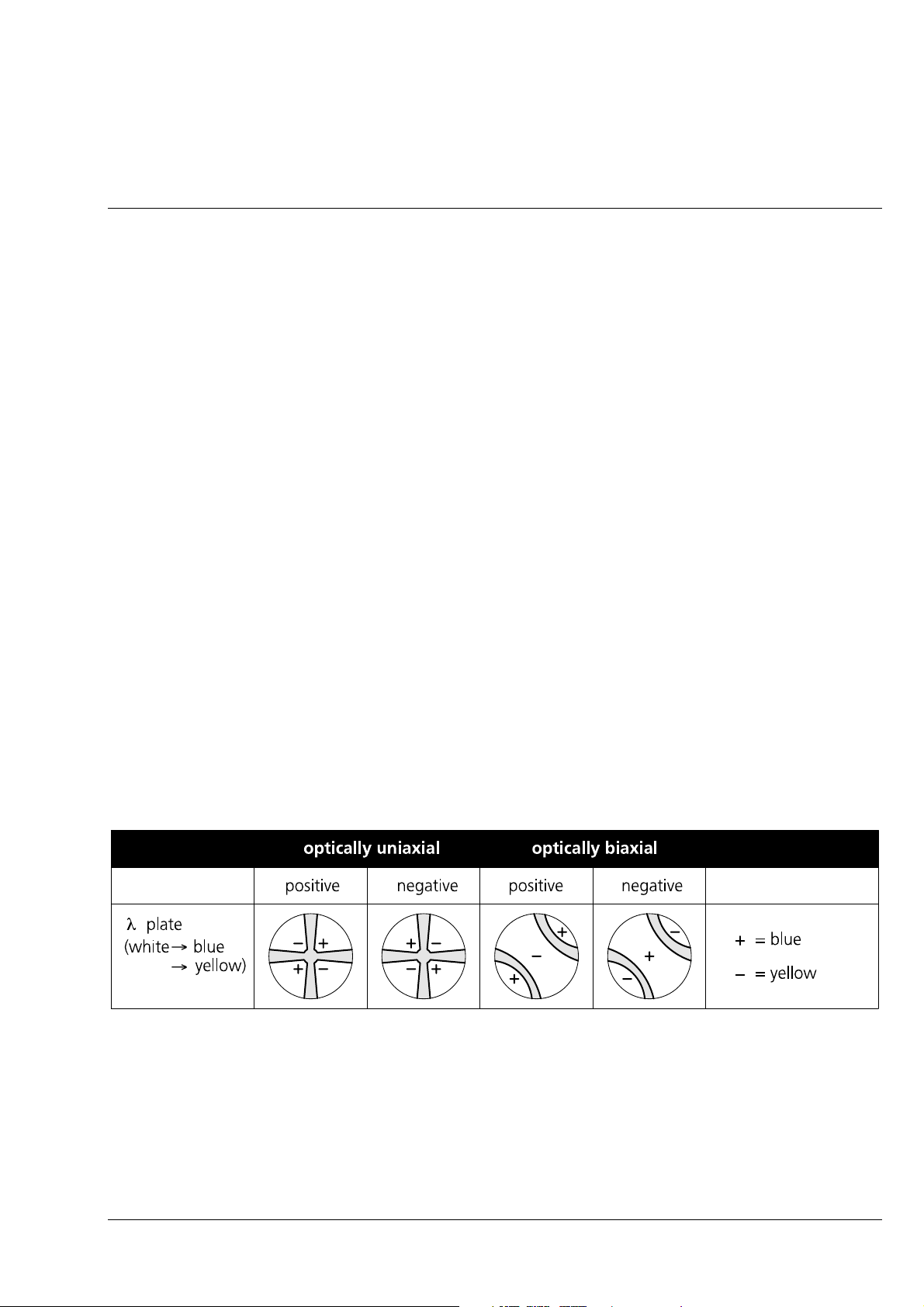
Axiolab A Carl Zeiss
Uniaxial Crystals
If the optical axis of a uniaxial crystal is oriented parallel to the observation direction, a dark cross which
can be surrounded by concentric interference rings (depending on birefringence and specimen thickness)
becomes visible in the conoscopic observation mode. These interference rings are also called isochromats
(from the Greek isos = equal and chroma = color).
st
The cross is maintained when the stage is turned. Observe the NE quadrant of the cross (1
quadrant;
counting is made counterclockwise).
If you use the λ-compensator:
• After insertion of the λ-compensator, the following appears in the first and third quadrant near the
center of the dark cross:
− yellow = optically negative
− blue = optically positive
Biaxial Crystals
If biaxial crystals show a cross in conoscopic observation which is resolved into two hyperbola legs when
the stage is turned, the acute bisectrix (1
st
center line) is oriented parallel to the observation direction.
Turn the stage until the dark hyperbola legs (isogyres) are in the first and third quadrant.
If you use the λ-compensator:
• The following appears after insertion of the λ-compensator:
− yellow = optically negative
− blue = optically positive
Fig. 3-8 Determine the optical character of crystals
If one optical axis of a biaxial crystal is oriented parallel to the observation direction, only one
☞
hyperbola leg is visible in conoscopic observation, the vertex of which lies in the center of the
field of view. When the stages are turned, the hyperbola leg moves around its vertex. The
determination of the optical character is performed in the same way.
B 40-015 e 06/99 3-11

Carl Zeiss Axiolab A
(5) Reflected-Light Polarization - Detection of Bireflection and Reflection Pleochroism
Application
Polished sections of ores, coals, ceramic products, certain metals and metal alloys display a different
reflection behavior, depending on the orientation of the crystals or the object details. Therefore, this
technique also represents a further contrasting method.
Bireflection
• Set the microscope as usual for examinations in reflected-light brightfield (see section 3.2.1)
• Pull out plane-glass pushrod (3-3/1).
• Insert polarization slider (3-3/3) until stop.
• Insert analyzer slider (3-3/4); adjusting lever in center position.
• Close aperture diaphragm (3-4/7) by 2/3 of its diameter.
− The object displays bireflection if any object details feature differences in brightness and color
which vary when the stage is rotated.
Reflection Pleochroism
• Pleochroism can be recognized by color changes in the object after stage rotation (reflected-light
polarizer slider (3-3/3) pushed in, analyzer slider (3-3/4) pulled out). (Rotary λ-compensator pulled out)
3-12 B 40-015 e 06/99

Axiolab A Carl Zeiss
3.2.4
The fluorescence technique allows fluorescent structures to be visualized with high contrast in a typical
fluorescence color. The examined material can be autofluorescent or may have been mixed with
fluorescent substances (fluorochromes).
The epi-fluorescence technique can be performed using equipment for simple fluorescence examinations
with the Axiolab A, together with the 6 V, 30 W halogen illuminator (3-9/1) and the standard brightfield
beam splitter.
The equipment consists of:
- a special FL filter slider (3-9/2) which is inserted
in the reflected-light illuminator H instead of
the standard filter slider.
- a dia. 25 excitation filter (3-9/3) especially for
the blue excitation of Epodye.
- a dia. 25 barrier filter (3-9/5) especially matched
to this excitation filter, which is inserted in one
of the two dust protection sliders (3-9/6).
Setting of Epi-Fluorescence
☞
This technique requires much light.
Turn the "illuminance" control (3-9/7)
to its right stop, fully open aperture
diaphragm (3-9/4) via the adjusting
wheel.
Fig. 3-9 Setting of epi-fluorescence
B 40-015 e 06/99 3-13

Carl Zeiss Axiolab A
3.2.5
Setting of Transmitted-Light Brightfield (KÖHLER Illumination)
Make the microscope ready for operation as
described in chapter 2 and section 3.1.
• Switch on the illumination, place a high-
contrast specimen on the stage, and focus
using the 10× objective.
• Close luminous-field diaphragm (3-10/3) via the
knurled wheel.
• Use drive (3-10/5) to move ABBE condenser
close to the upper stop position until the image
of the luminous-field diaphragm appears in
focus.
• Use the centering screws (3-10/2) to move the
luminous-field diaphragm to the center of the
field of view.
Fig. 3-10 Setting of transmitted-light
brightfield
• Open the luminous-field diaphragm until its
edge just disappears from the field of view.
• Control the contrast via the aperture diaphragm
(3-10/4), which should be open by approx. 2/3
of its size (marking on condenser positioned to
0.5).
For further information on the use of the
Axiolab A for transmitted-light examinations and
the relevant accessories please see the manual
Axiolab - Transmitted Light and Epi-Fluorescence
(G 42-130/II e).
3-14 B 40-015 e 06/99
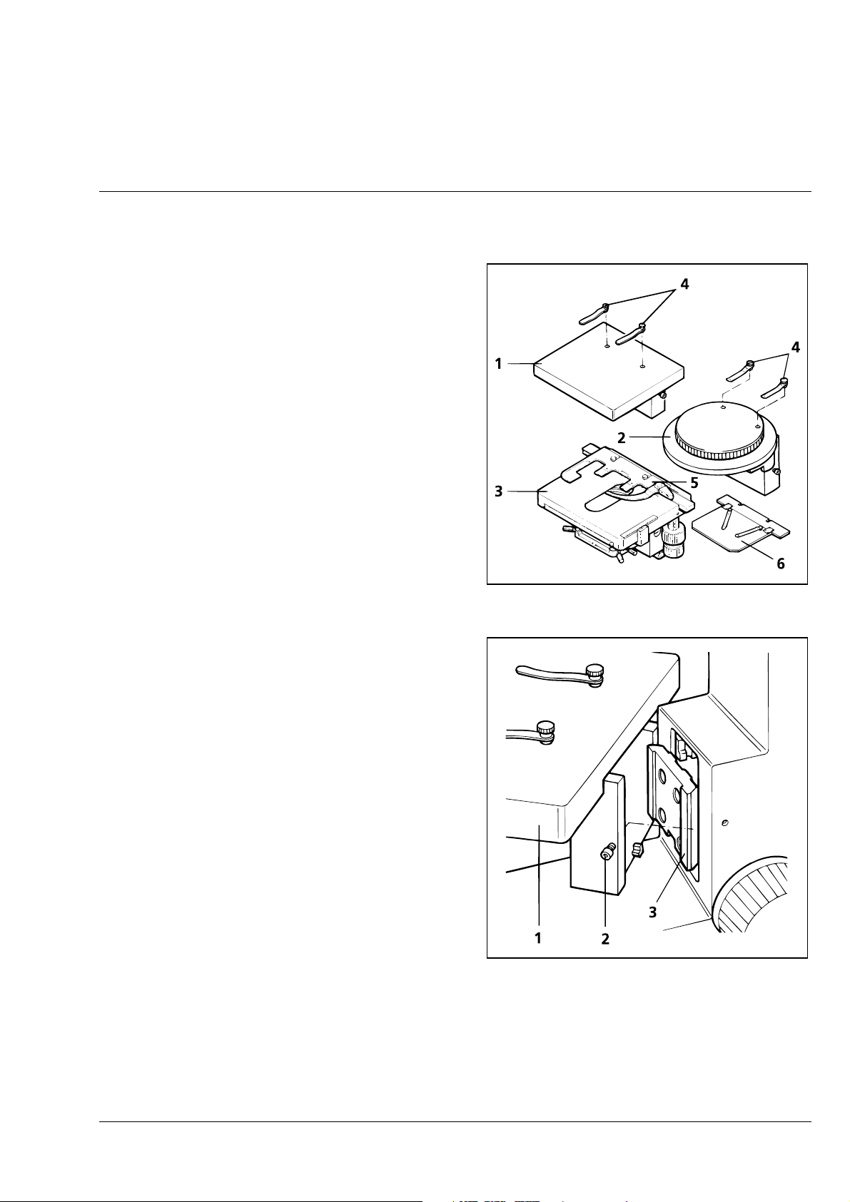
Axiolab A Carl Zeiss
3.3
The Axiolab A microscope is available with three
different stages:
- fixed stage (3-11/1),
- gliding stage (3-11/2) or
- mechanical stage (3-11/3).
The retaining clips (3-11/4) are used to hold
specimens mounted on a 26 × 76 mm microscope
slide. They are inserted into the drilled holes in the
specimen stage.
With the mechanical stage, the specimen holder
with spring clip ”R” (3-11/5) is used to guide the
above slides. For the examination of opaque
objects, the mechanical stage can be equipped
with the specimen holder A (3-11/6).
Attachment of Microscope Stages and Specimen Holders
The stages can be changed by the users
themselves:
• Loosen hexagonal screw (3-12/2) on the right
side of the stage until the stage (3-12/1) can be
removed from the dovetail (3-12/3).
The stage can be attached again and fixed in
reverse order.
If the maximum specimen height is
☞
20 mm, the stage is secured in the
upper stop position; for higher
specimens, the lower stage stop must
be used (specimen height up to max.
45 mm).
The mechanical stage can be secured
only in the upper stop position, and
therefore only allows specimen heights
up to 20 mm (only 18 mm with
specimen holder A).
Fig. 3-11 Stage selection
Fig. 3-12 Changing the microscope stage
B 40-015 e 06/99 3-15

Carl Zeiss Axiolab A
3.3.1
Attachment of Pol Rotary Stage
12
10
1
11
9
8
7
2
1
3
4
5
6
Fig. 3-13 Pol rotary stage- setting of specimen mount and stop
The stage clips (3-13/3) are used to mount the specimen on the Pol rotary stage (3-13/8). They are
inserted into two of the three drilled holes (3-13/9) and, depending on the size of the specimen carrier or
the search area, used diagonally, opposite to each other or parallel.
The Pol object guide (3-13/11) (accessory 473325-0000-000) provides a more convenient possibility. It is
inserted in the drilled holes (3-13/7) and secured using the screw (3-13/10). For this purpose, use the
ball-headed screwdriver (3-13/12) supplied. The plastic rings (3-13/1) increasing the knob diameter (313/4) for convenient operation from the side are particularly beneficial for screening.
To obtain a maximum screening area with the 24 × 48 specimen carrier size, mount the
☞
3-16 B 40-015 e 06/99
specimen as shown in Fig. (3-13/2).

Axiolab A Carl Zeiss
3.4
The polished section attachment from the line of accessories provides another possibility of holding
objects for examinations in incident light. It has been intended for use with the gliding stage.
☞
The polished section attachment accommodates
specimens of any shape with one processed
(ground and polished) surface and aligns them
parallel to the stage surface.
• Gliding stage (3-14/6) - or also fixed stage - at
the lower stop.
Use of Polished Section Attachment
Basically, the polished section attachment can also be used with the fixed stage. Use a
screwdriver to remove the two bolts (3-14/5) on the underside and place the attachment on
the fixed stage without any securing elements.
• Remove magnetically held plate (3-14/1) from
the polished section stage (3-14/4).
• Remove both retaining clips and insert two
bolts (3-14/5) of the polished section stage
(3-14/4) into the drilled holes of the gliding
stage (3-14/6).
• Use the retaining clip (3-14/3) to fix the
polished section (3-14/2) to the plate
(3-14/1) from below.
• Attach the specimen assembly to the
premounted polished section attachment.
• The two knurled screws (3-14/7) permit the attachment to be slightly tilted towards its support.
Should the microscope image be unilaterally out of focus in the field of view, this can be remedied by
slightly changing the tilt of the attachment.
Fig. 3-14 Use of polished section attachment
B 40-015 e 06/99 3-17

Carl Zeiss Axiolab A
3.5
Photomicrography and Videomicroscopy
The Axiolab A microscope can be changed from observation to photomicrography or videomicroscopy
via a pushrod (3-16/7 or 3-18/8) (pushrod pulled out for photomicrography or videomicroscopy). Since
this is a 100% changeover, simultaneous observation and photography is not possible.
Special adapters allow commercially available 35 mm cameras or microscope cameras (e.g. MC 80
DX
) to
be attached to the camera port of the Axiolab A. For the use of photomicrography equipment please see
the relevant manuals.
Fig. 3-15 Attach various camera systems to the Axiolab A phototube
3-18 B 40-015 e 06/99

Axiolab A Carl Zeiss
3.5.1
(1) Attachment of SLR Camera, e.g. CONTAX 167 MT
• Screw T2 adapter for the CONTAX bayonet (3-
16/3) on the 2.5× connector for T2 (3-16/4)
(456005-0000-000).
• Attach the camera housing (3-16/2) and the
cable release (3-16/1), if required.
• Loosen the three hexagonal screws (3-16/6) to
remove the dust cover (3-16/8) from the
camera tube (3-16/5) and insert the
premounted unit A in the camera tube.
• Align the camera unit in the required position
and tighten the three hexagonal screws (316/6).
• Pull out pushrod (3-16/7) completely for
photomicrography.
Attachment of Photomicrography Equipment
• When artificial-light color reversal film is used,
the CB 3 conversion filter provides the correct
color temperature of 3200 K.
• For daylight color reversal film, the CB 12
conversion filter must be used in addition to the
CB 3 conversion filter.
☞
If focusing is not to be made via the
viewfinder of the camera, the
component with the eyepiece reticle
must be screwed in the eyepieces (see
sections 1.5 and 2.3.1).
Fig. 3-16 Attachment of SLR camera, e.g.
CONTAX 167 MT
B 40-015 e 06/99 3-19

Carl Zeiss Axiolab A
Various T2 adapters for SLR cameras are listed below:
T2 adapters to SLR cameras Cat. No.
T2 adapter for CONTAX (CONTAX bayonet) 416010-0000-000
T2 adapter for OLYMPUS OM (OM bayonet) 416002-0000-000
T2 adapter for MINOLTA (SR bayonet) 416003-0000-000
T2 adapter for CANON (FD bayonet) 416004-0000-000
T2 adapter for NIKON (F bayonet) 416009-0000-000
T2 adapter for PENTAX (KA bayonet) 416011-0000-000
☞
For detailed information on SLR cameras please see operating manual from Carl Zeiss B 40046 e entitled "Photomicrography with 35 mm SLR Cameras".
3-20 B 40-015 e 06/99

Axiolab A Carl Zeiss
(2) Attachment of MC 80
Microscope Camera (35 mm Film Cassette)
DX
• Insert adapter 60 for microscope camera (3-
17/5) (456006-0000-000) in camera tube (317/6) and fix it using three hexagonal screws
(3-17/7).
• Insert projection lens P 2.5× (3-17/4) in adapter
60 for microscope camera (3-17/5).
• Attach MC 80
basic body (3-17/2) on
DX
adapter 60 for microscope cameras until stop
and fix it by clamping ring (3-17/3)
anticlockwise.
• Attach 35 mm film cassette Mot DX (3-17/1) to
the basic body in such a way that the contact
pins firmly engage in the relevant sockets.
• Pull out pushrod (3-17/8) completely for
photomicrography.
• When artificial light color reversal film is used,
the CB 3 conversion filter provides the correct
color temperature of 3200 K.
• For daylight color reversal film, the CB 12
conversion filter must also be used.
☞
For detailed information on the
MC 80
please see operating
DX,
manual from Carl Zeiss B 40-036 e,
"MC 80
Microscope Camera".
DX
Fig. 3-17 Attachment of MC 80
DX
B 40-015 e 06/99 3-21

Carl Zeiss Axiolab A
3.5.2
Attachment of Adapters for Video Cameras
The following video adapters with 60 mm interface permit the attachment of one-chip b/w and color
CCD cameras and 3-chip color CCD cameras to the camera port of the Axiolab A
Tube Adapter Cameras
.
A
XIOLAB
R
EFLECTED
LIGHT TUBE
60
WITH
MM
I
NTERFACE
456105
456105
60 C 2/3“
×
1.0
456119
60 C 1/3“ (3CCD)
×
0.5
456119
456107
456108
456107
60 C 2/3“
×
0.63
456108
60 C 1/3“
×
0.4
456106
456106
60 C 1/2“
0.5
456123
Zoom 60 C 2/3“
456123
0.4
×
×
... 2
C
AMERAS
WITH
C-M
OUNT
×
A
456115
-
456115
60 ENG 2/3“
×
1.0
456117
456117
60 ENG 2/3“
×
0.8
456121
Zoom 60 ENG 2/3“
456121
0.4
×
... 2
×
3-C
HIP
C
AMERAS
2/3“
WITH
BAYONET
3-C
456124
456124
Zoom 60 ENG
1/2“
0.5
×
... 2.4
456122
456122
Zoom 60 ENG 1/2“
0.4
×
... 2
×
456118
60 ENG 1/2“
×
0.63
×
456118
HIP
C
AMERAS
1/2“
WITH
BAYONET
3-22 B 40-015 e 06/99

Axiolab A Carl Zeiss
Attachment of video cameras:
• Loosen three hexagonal screws and remove dust cover from the Axiolab A camera tube.
• Screw video adapter or video zoom adapter with C-mount thread into the video camera.
Insert video adapter or video zoom adapter in ENG 2/3“ or ENG ½“ bayonet of the video camera and
clamp it tight.
• Insert premounted unit (video camera with video adapter or video zoom adapter) in the camera tube
of the Axiolab A, align it and fix it using the three hexagonal screws.
• Set the required zoom magnification factor via the wheel of the video zoom adapter.
• If required, adjust image brightness on the monitor by changing the lamp brightness on the
microscope stand.
☞
The instructions of the camera manufacturer must also be observed when operating the video
camera.
B 40-015 e 06/99 3-23

Carl Zeiss Axiolab A
3.6
Insertion of 8×××× Drawing Eyepiece
The 8× drawing eyepiece (444126-0000-000) is an accessory for microscopic drawing and can only be
used in combination with the binocular reflected-light tube 30°/20 H
1
on the Axiolab A. It contains a
beam splitter which allows the simultaneous observation of the microscope image and the drawing area.
Switch on the microscope as described in section
3.2 and set it for reflected-light brightfield
according to section 3.2.1.
• Remove one eyepiece (3-18/1) and insert the 8×
drawing eyepiece (3-18/3) in the binocular
reflected-light tube 35°/20 (3-18/2) until stop.
Swing 8× drawing eyepiece until the drawing
area (DIN A4 notepad) lying in front of the
stand appears symmetrically aligned also in the
field of view.
• Screw on the drawing eyepiece.
• Illuminate the drawing area in such a way that
it can be seen in the same quality as the
microscope image. If required, reduce the
brightness of the microscope image via the
illuminance control (3-2/7).
Fig. 3-18 Insertion of 8
drawing eyepiece
××××
• A special drawing pencil is supplied to facilitate
drawing.
If the image on the drawing area is too dark, an additional desk illuminator should be
☞
installed. We would recommend the use of spotlights with a homogeneous area illumination
(dia. 250 mm).
We would also recommend you to use a support for the drawing area, which should be 20
mm thick. This is the only way to ensure that the exact distance to the drawing eyepiece is
kept.
1
30°/20 means a viewing angle of 30° and the maximum field number 20.
3-24 B 40-015 e 06/99

Axiolab A Carl Zeiss
CARE, TROUBLESHOOTING AND SERVICE
Contents
4 CARE, TROUBLESHOOTING AND SERVICE....................................................................4-3
4.1 Maintenance of the Instrument........................................................................................4-3
4.2 Troubleshooting ..............................................................................................................4-4
4.3 Requesting Service...........................................................................................................4-6
B 40-015 e 06/99 4-1

Carl Zeiss Axiolab A
4-2 B 40-015 e 06/99

Axiolab A Carl Zeiss
4
4.1
CARE, TROUBLESHOOTING AND SERVICE
Maintenance of the Instrument
Maintenance of the Axiolab A is limited to the following operations:
• Cover the instrument with the dust cover after every use.
• Do not set up the instrument in a damp room, i.e. max. humidity < 85%.
• Remove dust from optical surfaces using a rubber blower or a natural hair brush. Use alcohol to
remove grease from brush, then dry the brush. Remove stubborn dirt and fingerprints using a dustfree cloth or leather cloth.
• Remove stubborn dirt (e.g. fingerprints) from optical surfaces using commercially available optics
cleaning cloths; if necessary, slightly moisten the cloths with petroleum ether. Clean the front lenses
of the objectives using petroleum ether, but do not use alcohol.
When using the Axiolab A in humid climatic zones, proceed as follows:
Store the Axiolab A in bright, dry and well ventilated rooms with a humidity of less than 85%; store
-
particularly sensitive components and accessories, such as objectives and eyepieces, in a dry closet.
When the equipment is stored in closed cases for a longer period of time, the growth of fungus can
-
be avoided by including cloths soaked in fungicide in the cases.
The risk of growth of fungus on opto-mechanical instruments always exists in the following conditions:
relative humidity of more than 75% and temperatures between +15° C and +35° C for more than
-
three days.
installation in dark rooms without air ventilation, and
-
dust deposits and fingerprints on optical surfaces.
-
B 40-015 e 06/99 4-3

Carl Zeiss Axiolab A
4.2
Troubleshooting
Troubleshooting on the Axiolab A microscope is limited to only a few actions:
• Checking the line cable
• Checking the set instrument voltage and changing the fuses
• Checking the illumination and changing the lamp
− Defective fuse(s) → change the fuses according to paragraph (1)
− defective halogen lamp → change the lamp according to paragraph (2) or (3)
(1) Check the Line Cable and Fuses and
Change Fuses
Make sure to disconnect the instrument from the line first!
Fig. 4-1 Changing the fuses
• Check line cable (4-1/1) and replace it, if
required.
• Use 2.0 mm watchmaker’s screwdriver to press
the two springs at the side of the fuse holder
(4-1/2) to the inside via the groove and remove
fuse holder.
• Check fuse inserts (4-1/3) and replace defective
fuses with new ones. Make sure to use only
T 0.8 A; 250 V; 5 × 20 mm fuses!
• Insert fuse holder again until the springs at the
side can be heard to engage.
• Connect the instrument to the line.
4-4 B 40-015 e 06/99

Axiolab A Carl Zeiss
(2) Changing the 6 V, 30 W Reflected-Light
Halogen Lamp
The following procedure is required to change the
lamp of the 6 V, 30 W reflected-light halogen
illuminator:
• Switch off the lamp supply; if required, allow
the illuminator to cool down for approx. 15
minutes.
• Disconnect the line cable from the line.
• Remove the connection cable of the reflected-
light illuminator from the socket at the rear of
the instrument.
• Turn the cover (4-2/3) to the left and remove it
in backward direction.
• To facilitate the lamp change, loosen the
hexagonal screw (4-2/1) by a few turns and
remove the mount (4-2/2) from the reflectedlight illuminator (the tools are listed together
with the accessories)
• Loosen both fixation screws (4-2/5) by turning them to the left and remove the carrier plate (4-2/4)
containing the lamp.
• Remove new 6 V, 30 W halogen lamp from the packaging and insert it into the mount (4-2/2); one
tip of the ceramic base must engage in the centering notch of the carrier plate, and the carrier plate
must fit well to the second tip.
Do not touch the lamp bulb with your bare hands; if required, clean the bulb using pure
☞
• Attach reflected-light illuminator again in such a way that the halogen lamp is positioned vertically.
Tighten hexagonal screw (4-2/1).
alcohol before switching it on for the first time to prevent dirt from burning in.
Fig. 4-2 Changing the 6 V, 30 W reflected-
light halogen illuminator
• Attach cover (4-2/3) and lock it by turning it to the right.
• Connect the cable of the reflected-light illuminator to the rear of the microscope stand.
B 40-015 e 06/99 4-5

Carl Zeiss Axiolab A
(3) Changing the 6 V, 30 W Transmitted-
Light Halogen Lamp
The following procedure is required to change the
lamp of the integrated 6 V, 30 W illuminator:
• Switch off the extern lamp supply; if required,
allow the illuminator to cool down for approx.
15 minutes.
• Disconnect the line cable from the line.
• Hold the ventilation grille (4-3/1) on its grip and
pull it off in upward direction.
• Remove the lamp insert by pressing its handle
(4-3/2) together.
• Replace the halogen lamp 6 V, 30 W (4-3/3).
Fig. 4-3 Changing the 6 V, 30 W
transmitted-light halogen lamp
Do not touch the lamp bulb with your bare hands; if required, clean the bulb using pure
☞
• Make sure that the lamp carrier plate exactly fits the positioning pins.
• Attach lamp insert again by slightly pressing the handle together
• Attach ventilation grille again until stop.
4.3
All repairs of mechanical, optical or electronic components inside the instrument and of the electrical
components of the Axiolab A may only be performed by Carl Zeiss service staff or specially authorized
personnel.
To ensure the optimum setting and trouble-free function of your microscope even for a longer period of
time, we would recommend you to conclude a service/maintenance contract with Carl Zeiss.
In the case of subsequent orders or when service is required, please get in touch with your local Carl
Zeiss agency.
alcohol before switching it on for the first time to prevent dirt from burning in.
Requesting Service
4-6 B 40-015 e 06/99

Axiolab A Carl Zeiss
Annex
List of Abbreviation ..................................................................................................................... A-3
-
Certification in Accordance with DIN EN ISO 9001 / DIN EN 46001............................................... A-5
-
EC Conformity Declaration.......................................................................................................... A-7
-
B 40-015 e 06/99 A-1

Carl Zeiss Axiolab A
A-2 B 40-015 e 06/99

Axiolab A Carl Zeiss
List of Abbreviations
A incident light, analyzer
AC Alternating C
urrent
Br. eyepieces suitable for spectacle wearers
CCD Charge-Coupled Device
CSA Canadian S
tandards Association
D transmitted light, filter attenuation in %
DIN German Standards Association
Dmr, d diameter
DX coding system for electronic data,
e.g. film speed
EG European Community
EMV electromagnetic compatibility
EN European standards
ENG Electronic N
ews Gathering
E-PL name of eyepiece type Epiplan
FAA free working distance
FL fluorescence
foc. focusing
HBO mercury vapor short-arc lamp
HF brightfield
Hg mercury
HLW halogen lamp
ICS Infinity Color corrected System
IEC International E
lectrotechnical Commission
IP International Protection
M metric thread
MC Microscope C
amera
NO North-East
OZ item number
P polarizer
PL plane
Pol polarization
R right
SLR Single L
ens Reflex
SK protection class
SW wrench opening, South-West
VDE Association of German Electrotechnicians (Verband Deutscher Elektrotechniker)
B 40-015 e 06/99 A-3

Carl Zeiss Axiolab A
T slow-blow fuse type
TV television
T2-Adapter standard adapter for 35 mm cameras
A-4 B 40-015 e 06/99
 Loading...