


Zeiss Humphrey Field Analyser II i-Series User manual 1
HUMPHREY®
FIELD ANALYZER II - i series USER’S GUIDE
Model 720i • Model 740i • Model 745i • Model 750i
Carl Zeiss Meditec Inc.
5160 Hacienda Drive
Dublin, CA 94568
General Inquiries (925) 557-4100
(877) 486-7473
www.meditec.zeiss.com
Customer Service (877) 486-7473
In Europe please contact:
Carl Zeiss Jena GmbH
Carl Zeiss Promenade 10
Jena 077405
Germany
Ph: +49-3641-642076
Fax: +49-3641-642155
www.zeiss.de
Copyright
© 2003 Carl Zeiss Meditec Inc. All rights reserved.
Trademarks
Humphrey Field Analyzer is a registered trademark of Carl Zeiss Meditec Inc., STATPAC, FastPac, and SITA are trademarks of Carl Zeiss Meditec Inc., Hewlett-Packard and LaserJet are registered trademarks of Hewlett-Packard Corporation. IBM is a registered trademark of the International Business Machines Corporation. GoPrint is a trademark of the AeroComm company.
Every effort has been made to ensure that the information contained in this manual is true and correct at the time of printing. Any omissions or errors are unintentional and will be corrected in future releases.
This book may not be reproduced in whole or in part by any means of information storage, retrieval, or reproduction without written permission from Carl Zeiss Meditec Inc.

Humphrey® Field Analyzer II - i series
User’s Manual Revision Control
PART NUMBER |
REVISION |
TITLE |
RELEASE DATE |
51680-1 |
B |
Humphrey® Field Analyzer II - i series |
3-2003 |
|
|
User’s Guide |
|
|
|
Models 720i, 740i, 745i, 750i |
|


Table of Contents (this manual contains 314 pages)
1Introduction/ Instrument Setup
(18 pages)
2General Operation
(24 pages)
3Setting-up Tests
(24 pages)
4Test Parameters &
Strategies
(16 pages)
Introduction/Instrument Setup |
1-1 |
About Visual Fields |
1-2 |
The Humphrey Advantage |
1-5 |
Using This Guide |
1-8 |
Safety Precautions |
1-9 |
System Components |
1-12 |
Additional Components |
1-14 |
System Assembly |
1-17 |
General Operation |
2-1 |
General Information |
2-2 |
|
|
The Main Menu Screen |
2-9 |
|
|
System Setup |
2-10 |
|
|
Additional Setup |
2-21 |
|
|
Help Screens |
2-23 |
Setting-up Tests |
3-1 |
Selecting the Test Pattern and Test Eye |
3-2 |
Entering Patient Data |
3-8 |
Using Trial Lenses |
3-19 |
Preparing the Patient |
3-22 |
Test Parameters & Strategies |
4-1 |
Setting Test Parameters |
4-2 |
Test Strategies |
4-4 |
SITA™ Testing |
4-10 |
Blue-Yellow (SWAP) Testing |
4-11 |
Alternate Color Testing |
4-16 |
REV. B 02/03 PN 51680-1 |
HUMPHREY FIELD ANALYZER II - i series |
|
|

5Testing
(18 pages)
6Test Reliability
(8 pages)
7STATPAC Analysis &
Printing Results
(30 pages)
Testing |
5-1 |
Start Test Options |
5-2 |
Monitoring and Maintaining the Patient’s Eye Position |
5-4 |
Supplemental Testing |
5-7 |
Test In Progress |
5-10 |
Test Complete Options |
5-14 |
Testing: A Step-by-Step Guide |
5-16 |
Test Reliability |
6-1 |
Factors Affecting Reliability |
6-2 |
Patient Compliance |
6-2 |
Patient Fixation |
6-3 |
Trial Lenses |
6-3 |
Evaluating Reliability |
6-4 |
Fixation Losses |
6-4 |
False Positive Errors |
6-4 |
False Negative Errors |
6-6 |
Fluctuation Values |
6-6 |
STATPAC Analysis & Printing Results |
7-1 |
Introduction to STATPAC Analysis |
7-2 |
Threshold Test Printout Formats |
7-4 |
SITA Printout Formats |
7-21 |
Blue-Yellow Printout Formats |
7-23 |
Printing Current Threshold Test Results |
7-25 |
Screening Printout Formats |
7-26 |
Printing Current Screening Test Results |
7-27 |
Printing Previously Saved Test Results |
7-28 |
Grayscale Symbols |
7-30 |
Remote Printer Access |
7-30 |
REV. B 02/03 PN 51680-1 |
HUMPHREY FIELD ANALYZER II - i series |
|
|

8File Functions
(20 pages)
9Database Management
(22 pages)
10Custom Testing
(20 pages)
File Functions |
8-1 |
|
File Functions Menu |
8-2 |
|
Retrieving the File Directory |
8-4 |
|
Selecting Tests from the Directory |
8-6 |
|
Performing File Functions |
8-11 |
|
Organizing Patient Files |
8-20 |
|
Database Management |
9-1 |
|
|
|
|
Introduction to Database Management |
9-2 |
|
|
|
|
Patient Database Protection Procedures |
9-3 |
|
|
|
|
Configuration Backup and Restore |
9-5 |
|
|
|
|
How to Handle Database Failures |
9-10 |
|
|
|
|
Merge Database |
9-20 |
|
|
|
|
Cleanup Hard Disk Database |
9-21 |
|
|
|
|
Practices with Multiple Humphrey Field Analyzers |
9-22 |
|
|
|
|
Care and Handling of Removable Storage Media |
9-22 |
|
|
|
|
Custom Testing |
10-1 |
|
|
|
|
Creating Custom Tests |
10-2 |
|
|
|
|
Deleting Custom Tests |
10-15 |
|
|
|
|
Performing Custom Tests |
10-17 |
|
|
|
|
Printout Format |
10-19 |
|
|
|
|
REV. B 02/03 PN 51680-1 |
HUMPHREY FIELD ANALYZER II - i series |

11Kinetic Testing
(62 pages)
12Care & Cleaning
(14 pages)
Appendix
(36 pages)
Index
(6 pages)
Kinetic Testing |
11-1 |
Introduction to Kinetic Testing |
11-2 |
Performing Manual Kinetic Perimetry |
11-3 |
Pre-defined Kinetic Test Patterns |
11-14 |
Running Automated Kinetic Tests |
11-15 |
Social Security Administration Kinetic Disability Test |
11-24 |
Special Mapping |
11-27 |
Viewing Kinetic Tests |
11-40 |
Printing Kinetic Tests |
11-43 |
Designing a Custom Kinetic Test Pattern |
11-48 |
Creating the SSA Aphakic (Size IV) Disability Test |
11-57 |
Care & Cleaning |
12-1 |
General Use Principles |
12-2 |
Cleaning the HFA II |
12-2 |
Replacing Parts |
12-4 |
Operating the Printrex Printer |
12-10 |
Touch Screen Calibration |
12-12 |
Using Data Disks |
12-13 |
A HFA II Product Specifications |
A-1 |
B Warranty Statement and Notification of Copyright |
B-1 |
C Icon Glossary |
C-1 |
D Goldmann Conversion Tables |
D-1 |
E Test Patterns |
E-1 |
F Installing New HFA II Software |
F-1 |
G How SITA Works / Acknowledgments |
G-1 |
H Troubleshooting / Parts List |
H-1 |
REV. B 02/03 PN 51680-1 |
HUMPHREY FIELD ANALYZER II - i series |
|
|

Introduction/Instrument Setup |
1 |
|
|
About Visual Fields |
1-2 |
|
The Humphrey Advantage |
1-5 |
|
Using This Guide |
1-8 |
|
Safety Precautions |
1-9 |
|
System Components |
1-12 |
|
Additional Components |
1-14 |
|
System Assembly |
1-17 |
You are about to use the most advanced automated perimeter available, the Humphrey® Field Analyzer II (HFA II). This introductory section covers general information about the HFA II, including a brief discussion of visual fields and a summary of important instrument features.
After reading Section 1 you will be familiar with:
• the importance of visual field testing
• general principles of perimetry
• unique features of the Humphrey Field Analyzer II
• installation and safety precautions
• connecting optional external printers.
 Welcome
REV. B 02/03 PN 51680-1 |
HUMPHREY FIELD ANALYZER II - i series |

1-2 |
INTRODUCTION / INSTRUMENT SETUP |
ABOUT VISUAL FIELDS
When asked to assess one’s own vision, the average person often will confidently reply “I see 20/20”, “20/100” or whatever the result of their visual acuity test. Fortunately, doctors appreciate the complexities involved in evaluating visual function and rely on an extensive and varied battery of diagnostic tests and instruments as part of the ocular examination. Without question, one of the most essential tools in the modern ophthalmic office is the computerized perimeter, used to evaluate the visual field.
The purpose of visual field testing, or perimetry, is to provide information critical to:
•diagnosing ocular diseases, especially glaucoma
•evaluating neurological diseases
•monitoring the progress of ocular and neurological diseases.
Visual field testing can lead to early detection and treatment of disease. In the case of glaucoma, visual fields play a major role in identifying visual field defects and evaluating the efficacy of the therapy used to control the disease process.
What visual field |
When evaluating visual performance, clinicians are primarily interested in two retinal |
tests measure |
functions: resolution and contrast sensitivity. Resolution is the ability to identify discrete forms |
|
(letters, numbers, symbols), and is commonly measured with the visual acuity test. Resolution |
|
rapidly diminishes with increasing distance from the fovea and is, therefore, a poor indicator |
|
of overall visual performance. |
|
A better means of evaluating visual function—especially those areas less sensitive than the |
|
fovea—is contrast sensitivity testing. Contrast sensitivity is the ability to detect a stimulus (spot |
|
of light or other target) against a darker or brighter background. Standard Humphrey |
|
perimetry may be thought of as contrast sensitivity testing applied throughout the peripheral |
|
visual field. |
|
In perimetry, the term “threshold” is used to describe a very specific level of stimulus detec- |
|
tion. The threshold represents the point at which a stimulus is seen 50% of the time and |
|
missed 50% of the time. The assumption is that all stimuli brighter than the threshold value |
|
will be seen and all stimuli dimmer will be missed. Reviewing the threshold value at each point |
|
tested in the visual field is an important part of the diagnostic process. |
|
Visual field tests can yield information that is general in nature, as with screening tests, or |
|
more exacting and quantitative, as with threshold tests. In deciding which test type is most |
|
appropriate for a patient the practitioner is influenced by many factors, including the patient’s |
|
presenting complaint, family history, age, degree of cooperation, and time available to run |
|
the test. |
REV. B 02/03 PN 51680-1 |
HUMPHREY FIELD ANALYZER II - i series |
|
|
INTRODUCTION / INSTRUMENT SETUP |
1-3 |
Normal versus |
The visual field normally extends more than 90° temporally, 60° nasally and superiorly, |
|||
pathologic fields |
and about 70° inferiorly. That means a person can potentially perceive stimuli within this |
|||
|
range while staring at a fixed point. |
|
|
|
|
|
Superior |
|
|
|
|
60° |
|
|
|
Nasal |
60° |
90° |
Temporal |
|
|
|
||
70° Inferior
Figure 1.1: The Boundaries of the Normal Visual Field
A more comprehensive understanding of the normal field takes into account that visual sensitivity is not constant (or equal) throughout the range. As previously stated, vision is most acute at the fovea and decreases toward the periphery of the retina. It is easy to see why the visual field is often expressed as a “hill of vision in a sea of darkness”.
FOVEA 
BLIND
SPOT
Figure 1.2: The Normal Hill of Vision
Several factors affect the normal hill of vision causing variations in its overall height and shape. Among them are a patient’s age, ambient light, stimulus size, and stimulus duration. In general, deviations from the normal hill are viewed as visual field defects and caused by some pathological change.
REV. B 02/03 PN 51680-1 |
HUMPHREY FIELD ANALYZER II - i series |
1-4 |
INTRODUCTION / INSTRUMENT SETUP |
|
A defect (or scotoma) is categorized as either relative or absolute. A relative defect is an area |
|
|
|
that has depressed vision or less than normal sensitivity; an absolute defect is an area where |
|
the perception of light is absent. The point at which the optic nerve enters the retina is referred |
|
to as the blind spot, and is an example of an absolute scotoma. |
|
Some defect patterns are characteristic of certain diseases, a fact which makes visual field |
|
testing a valuable part of the diagnostic process. Furthermore, by having patients repeat the |
|
same tests at later dates, practitioners gain insight into the progression of the disease and the |
|
effectiveness of treatment. |
Methods of testing |
Over the years, visual field testing devices have varied in size, complexity, and testing |
the visual field |
methodology. The fundamental premise has remained the same, however; patients must |
|
respond when they see a stimulus. |
|
In kinetic testing, a target of fixed stimulus characteristics is moved into the visual field from a |
|
non-seeing area, until it is detected by the patient. Typically, the target is brought toward the |
|
center from several directions and the operator marks the location at which the patient first |
|
detects the target (threshold point). |
|
Kinetic test results can only be reliably related to specific parts of the visual field if points are |
|
joined to form an isopter, or ring of equal contrast sensitivity. Targets of varying size and |
|
brightness are used during one kinetic test, and for each different target, a different isopter is |
|
mapped. When reviewing several isopters, the clinician is visualizing different tiers in the hill |
|
of vision. |
|
A second method of evaluating retinal function is known as static threshold testing. The term |
|
“static” refers to a stationary (rather than moving) stimulus being used. |
|
In static testing, predefined test locations in the visual field are probed. Through a series of |
|
stimulus presentations of varying brightness intensities, the threshold value is determined for |
|
each test point. When evaluating static test results, clinicians are looking at the topography or |
|
contour of the hill of vision, and whether depressions are evident. |
Patient fixation and |
In order for any visual field test to be clinically useful, it must yield reliable results. One |
test reliability |
important factor affecting reliability is the steadiness of patient fixation. Unless the eye being |
|
tested accurately fixates on the target while responding to stimuli, the results are unreliable. |
|
Other factors adversely affecting reliability are: |
|
• patient fatigue and anxiety |
|
• poor test instructions |
|
• patient discomfort |
|
• improper near vision correction for central testing. |
|
|
REV. B 02/03 PN 51680-1 |
HUMPHREY FIELD ANALYZER II - i series |
|
|

INTRODUCTION / INSTRUMENT SETUP |
1-5 |
|
Reasons for |
Certainly the advancements in microprocessor technology within the last 20 years have had |
|
computerized perimetry |
a profound effect on perimetry. Perimeters have evolved into a more precise measuring tool |
|
|
yielding highly repeatable results. |
|
|
These changes are better appreciated by examining the benefits computerized perimeters bring |
|
|
to both patient and professional: |
|
•Reproducible testing conditions.
•Data storage capability; results can be compared over time and analyzed using expert system software.
•More sensitive testing; many researchers claim static perimetry to be superior to the kinetic method for identifying defects. Performed manually, static testing would be too time-consuming.
•Ease of operation; menu-driven software makes automated perimeters easy to learn and use.
THE HUMPHREY ADVANTAGE
Over 15 years of advancements in research, design and development are reflected in the Humphrey® Field Analyzer II. Equally important, the latest models represent improvements suggested by users from around the world who have generously shared their best ideas with Carl Zeiss Meditec. With over 30,000 Humphrey Field Analyzers in use worldwide, Carl Zeiss Meditec took on the challenge of improving the testing experience for the patient, the operator, and the practitioner. Here are some of the features which differentiate the HFA II from all other autoperimeters available today.
Ergonomic design |
The HFA II relieves many physical discomforts |
|
associated with visual field testing. The chin |
|
rest and bowl shape allow patients to assume a |
|
more natural and relaxed sitting position when |
|
taking tests. |
P
a
t
|
|
|
|
f |
|
|
|
m |
|
|
|
o |
|
|
|
C |
|
|
|
|
t |
|
|
|
|
n |
|
|
|
e |
|
|
|
|
i |
|
|
|
|
ort
e c n
a i l p m
The special power table and instrument slider improve patient comfort by permitting the HFA II to extend out to the patient instead of the patient stretching toward the instrument. This is especially important for wheelchair bound patients.
R e
l i
a
b l e R
e
s
u
l
ts
|
t |
a |
|
P |
|
i
o C
t en
The patient response button is easy to operate,
especially for patients who have limited use of their hands; for instance, patients with arthritis. The uniquely-shaped button may be placed on a knee, lap or the arm of a chair for better leverage. The cord angles away from the patient for greater comfort. The response button will beep each time it is pressed to give immediate feedback to the patient and to the user.
REV. B 02/03 PN 51680-1 |
HUMPHREY FIELD ANALYZER II - i series |
1-6 |
|
INTRODUCTION / INSTRUMENT SETUP |
Easy operation |
|
Sophisticated instrumentation need not be complicated. The HFA II offers a number of features |
|
||
|
|
intended to make the instrument easier to use: |
|
|
• Touch screen design speeds data input. |
|
|
• Menu and icon commands simplify operation. |
|
|
• On-screen video eye monitor is standard on all models. |
|
|
• Confirmation screens reduce unintentional data loss. |
|
|
• A keyboard and trackball or mouse can be connected to the HFA II as optional data |
|
|
input devices. |
Speedy testing |
|
Carl Zeiss Meditec’s SITA™ testing strategies allow precise visual field measurements |
|
|
with unprecedented speed. With the SITA strategies, users can obtain visual field information in |
|
|
half the time it takes using conventional testing algorithms without compromising accuracy. |
|
|
SITA represents the very latest in autoperimetry technology and it is only available with your |
|
|
Humphrey Field Analyzer II. |
Sophisticated data |
|
The Humphrey Field Analyzer’s statistical software, STATPAC™, provides immediate expert |
analysis with STATPAC™ |
|
system analysis of visual field test results. With STATPAC you can analyze test results at the time |
|
|
of examination, store test results and analyze them at your convenience, or recall previously |
|
|
stored tests to analyze for comparative purposes. |
|
|
STATPAC includes several exclusive features to help you identify visual field change: |
|
|
• Using results from a single test, STATPAC can point out suspicious areas that otherwise |
|
|
might not be evident until subsequent tests were done. |
|
|
• STATPAC can identify areas that look suspicious but which, in fact, compare favorably |
|
|
with normals data. |
|
|
• Using results from a series of tests, STATPAC provides a highly sensitive and informative |
|
|
analysis of changes in the patient’s visual field over time. |
|
|
• The Glaucoma Hemifield Test (GHT) compares points in the superior and inferior |
|
|
hemifields to provide a plain language analysis of test results. |
|
|
• The HFA II provides separate databases for STATPAC analysis. These include databases |
|
|
for SITA and Blue-Yellow perimetry, in addition to the well-established databases for |
|
|
Full Threshold and FastPac test results. |
|
|
• Another database consisting of stable glaucoma patients is used with the Glaucoma |
|
|
Change Probability Analysis for following change in the progress of the disease. This |
|
|
analysis is only available with Full Threshold testing. |
|
|
|
REV. B 02/03 PN 51680-1 |
HUMPHREY FIELD ANALYZER II - i series |
|
|
INTRODUCTION / INSTRUMENT SETUP |
1-7 |
||
Blue-Yellow (SWAP) testing |
|
Blue-Yellow perimetry, also known as Short Wavelength Automated Perimetry, or SWAP, |
|
|
|
||
(model 745i and 750i) |
|
has performed better than standard computerized perimetry according to published |
|
|
|
longitudinal studies. Working independently, researchers from U.C. Davis and U.C. San Diego |
|
|
|
have found that Blue-Yellow perimetry identified early glaucomatous visual field defects years |
|
|
|
before they could be detected using standard white-on-white perimetry. |
|
|
|
Blue-Yellow perimetry differs from standard static White-on-White perimetry only in that a |
|
|
|
carefully chosen wavelength of blue light is used as the stimulus, and a specific color and |
|
|
|
brightness of yellow light is used for the background illumination. For more information on |
|
|
|
Blue-Yellow perimetry, see Section 4 and Section 7. |
|
Automatic fixation monitoring |
|
The HFA II employs several methods for ensuring that patients maintain proper fixation of the |
|
|
|
target during testing. All models are equipped with a video eye monitor which presents a view |
|
|
|
of the patient’s eye on-screen so that users can ensure proper patient fixation. Every HFA II also |
|
|
|
offers standard Heijl-Krakau blind spot monitoring. |
|
|
|
Models 740i, 745i and 750i also offer Gaze Tracking: a patented, high precision system which |
|
|
|
uses real-time image analysis to verify the patient is looking at the fixation target and not |
|
|
|
looking around. The gaze tracking device is unaffected by the patient’s head position. A |
|
|
|
continuous record of fixation is available for monitoring on the test screen throughout the test. |
|
|
|
The gaze track graph is included on the printout to provide a permanent record of the patient’s |
|
|
|
fixation. |
|
|
|
For patients who require a trial lens, the model 750i uses Head Tracking and Vertex Monitor- |
|
|
|
ing to help ensure that the patient’s eye is both centered behind the lens and is held at the |
|
|
|
proper distance from the lens. These features help to eliminate the trial lens as a possible |
|
|
|
source of unreliable visual field results. |
|
Data protection features |
|
Visual field results need to be saved and protected for future use. The HFA II offers you a |
|
|
|
number of data storage methods to file the results. Floppy disk data storage is available with all |
|
|
|
models of the HFA II. Magneto-optical disk backup is available on the model 750i of the HFA II |
|
|
|
and is optional with other models. There are a number of additional data protection features |
|
|
|
that work internally to safeguard your data from serious loss or damage. This User’s Guide |
|
|
|
describes in great detail the procedures for creating extra copies of your data. |
|
Information on the internet |
|
New information about your HFA II may be found on the Carl Zeiss Meditec web site. The |
|
|
|
internet address is : www.meditec.zeiss.com |
|
|
|
|
|
REV. B 02/03 PN 51680-1 |
HUMPHREY FIELD ANALYZER II - i series |
1-8 INTRODUCTION / INSTRUMENT SETUP
USING THIS GUIDE |
|
|
To fully appreciate the capability of the HFA II and develop good testing techniques, we |
|
recommend that you rely on the User’s Guide as your training and reference manual. It has |
|
been designed to make learning easy. The concise step-by-step instructions and accompanying |
|
illustrations help you get started quickly and with more confidence. |
|
We think you will enjoy working with the HFA II. The friendly touch control makes it inviting to |
|
learn and easy to operate. For optimum results: |
|
• Read your guide in the order written. |
|
• Read it while sitting at the instrument. |
|
• Practice using the HFA II by first testing staff members before using it with patients. |
Model differentiation |
This guide contains instructions for Models 720i, 740i, 745i and 750i. Although much of the |
|
information is relevant to all models, some information only applies to particular models. |
|
When a feature or function applies to specific models, this guide specifies the model |
|
number(s), often in parentheses, in a prominent location. An example of this is found in the |
|
previous discussion of Blue-Yellow testing (previous page). Conversely, model numbers are |
|
not specified when information is standard or optional on all models. |
|
You can find the model number of your instrument on the rear panel of the HFA II or you may |
|
access this information via the “i ” button located in the upper, left-hand corner of the screen |
|
(see Section 2: “The Information “i ” Button”). If you are unsure about the particular |
|
capabilities of your instrument, refer to Appendix A: “HFA II Product Specifications”. |
Text conventions |
The terms “select,” “choose,” and “press” are used interchangeably. Each term means to |
|
initiate an operator action using the touch screen, external keyboard, trackball, or mouse. The |
|
terms “hard disk” and “hard drive” are used interchangeably in reference to the data storage |
|
device standard on all HFA II models. |
|
UPPER CASE LETTERS are reserved for references to specific command buttons found on the |
|
touch screen. The exceptions to this are messages on test printouts, the words STATPAC, SITA, |
|
SWAP, HFA II, and headings. |
|
Italicized words are used to identify the icon buttons on the right border of the screen, the |
|
titles of figures, pictures, tables, and special notes in this manual. |
|
Bold words are used to highlight warnings and section headings. |
Additional references |
The User Guide cannot possibly cover every situation you may encounter with the HFA II, |
|
especially interpretation questions. Your HFA II comes with a copy of The Field Analyzer |
|
Primer which provides an overview of visual field results. Automated Static Perimetry, |
|
Second Edition, by Douglas R. Anderson and Vincent Michael Patella (Mosby, Inc., St. Louis), |
|
is recommended for in-depth information and analysis of visual fields. |
|
|
REV. B 02/03 PN 51680-1 |
HUMPHREY FIELD ANALYZER II - i series |
|
|
INTRODUCTION / INSTRUMENT SETUP |
1-9 |
SAFETY |
|
PRECAUTIONS |
|
|
The Humphrey Field Analyzer II complies with UL, CSA, EN and IEC safety requirements. |
|
Follow all warnings and precautions to ensure the safe installation and operation of the |
|
Humphrey Field Analyzer. |
|
CAUTION: This instrument is NOT anesthetic-proof. Do NOT use it in the presence |
|
of a flammable anesthetic since this creates a risk of explosion! |
General safety requirements |
• Although the Humphrey Field Analyzer II is designed for continuous operation, it should |
|
be turned off and covered with the dust cover when not used for an extended period of |
|
time. The HFA II should be used in a cool, dry and dust-free setting. |
|
• The HFA II is classified as Type B, class I protection equipment. To prevent electric |
|
shock, the instrument must be plugged into an earth grounded outlet. |
|
• Do NOT connect or disconnect cables while power is on. |
|
• Do NOT place any objects on top of the instrument. |
|
• Do NOT place any container holding liquid near the instrument. |
|
• Do NOT place the dust cover on the instrument while the instrument is powered on. |
|
• Do NOT attempt to open the front or rear covers on the HFA II. Only authorized Carl |
|
Zeiss Meditec Service personnel should perform repairs on your instrument. |
Installation safety |
• The Humphrey Field Analyzer II is equipped with a three-prong plug. The instrument |
precautions |
should be plugged into a correctly wired outlet with a ground receptacle. If the plug |
|
does not fit the outlet, contact an electrician. Do NOT disable or remove the ground pin. |
|
• Do NOT overload your AC outlet. |
|
• If the cord or plug is damaged, do NOT continue to use the instrument. Electrical shock |
|
or fire hazard may result. Call Carl Zeiss Meditec Customer Service for replacement. |
|
• Do not block the ventilation openings. These allow for the release of heat generated |
|
during operation. A buildup of heat due to blockage can cause failures which may |
|
result in a fire hazard. |
|
• Use only a stand or table recommended by Carl Zeiss Meditec. |
|
• If the stand or table has casters, do NOT try to roll it in deep pile carpet or over objects |
|
on the floor such as cables and power cords. Lock the casters to secure the table. |
|
• Do NOT place the instrument on an uneven or sloped surface. |
|
• Do NOT use accessories that are not designed for this instrument. Use only those parts |
|
recommended by Carl Zeiss Meditec to achieve optimum performance and safety. |
|
Accessories must meet UL, CSA, EN, and IEC safety standards. |
|
• Do NOT use the instrument in or near wet or moist environments. |
|
|
REV. B 02/03 PN 51680-1 |
HUMPHREY FIELD ANALYZER II - i series |
1-10 |
INTRODUCTION / INSTRUMENT SETUP |
|
CAUTION: Always replace fuses with same type or rating. Failure to do so may |
|
|
|
create a fire risk. Refer to fuse ratings listed on the label on the rear panel of the instrument |
|
or on the table near the fuse holder. See Section 12. |
Peripheral Placement |
NOTE: To maintain patient safety, peripheral devices such as printers must be placed at least |
Instructions |
1.5 meters (4.9 feet) away from the patient, such that the patient cannot touch a peripheral |
|
device with any part of his or her body while being examined. In addition, the instument |
|
operator must not attempt to touch the patient and a peripheral device at the same time while |
|
examining the patient. |
Radio and TV interference |
The Humphrey Field Analyzer II has passed all domestic and international electromagnetic |
|
emission/suppression standards. However, it still generates small amounts of radio frequency |
|
energy and may cause interference to radio, television or other instruments. If the HFA II does |
|
cause interference to radio or television reception, the following measures may be necessary: |
|
• Plug the Humphrey Field Analyzer II into a different outlet so that the |
|
instrument and the receiving device are on different branch circuits. |
|
• Reorient the HFA II with respect to the TV or the radio antenna. |
|
• Move the receiving device and the HFA II away from each other. |
|
• Use only shielded communication cables. |
|
|
REV. B 02/03 PN 51680-1 |
HUMPHREY FIELD ANALYZER II - i series |
|
|
INTRODUCTION / INSTRUMENT SETUP |
1-11 |
|
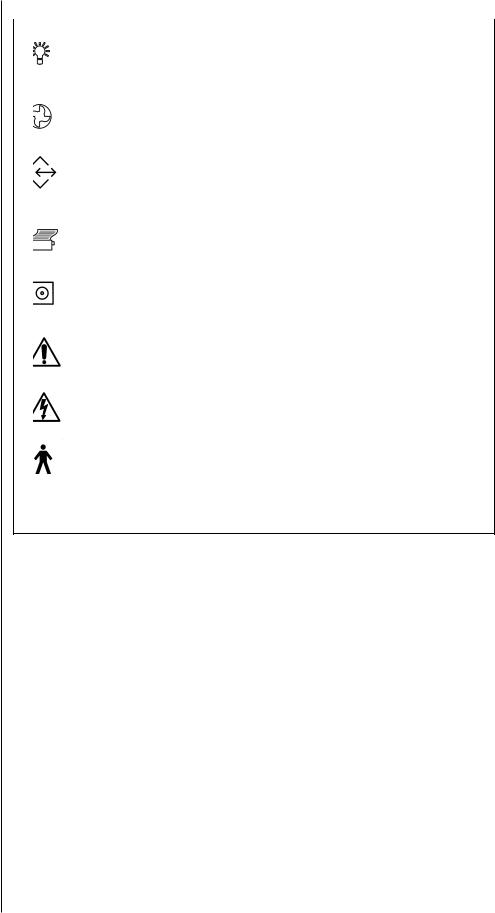
Symbol definitions |
The following symbols appear on the HFA II: |
|
|
|
|
|
Power On |
Power Off |
|
Projector Bulb |
Brightness |
Air Intake Filter |
USB Port |
|
Serial RS-232 |
VGA Monitor |
|
Communication Port |
|
|
|
Keyboard |
|
Printer |
|
|
|
Mouse |
|
Floppy Disk Drive |
Network |
|
Important Instructions |
Fuse |
|
Found in Manual |
|
|
Uninsulated High Voltage |
Patient Response |
|
Button |
||
Inside the Instrument |
||
|
||
Risk of Electric Shock |
|
|
|
Data |
|
Type B Class I |
|
Figure 1.3: HFA II Symbol Definitions
Power on |
The power switch is located on the rear panel of the instrument. The room lights should be |
|
dimmed or off when turning on the HFA II. Once engaged, the HFA II begins performing a self- |
|
diagnostic checkup. In the event the computer detects a problem, a message will appear on the |
|
start-up screen. Call Carl Zeiss Meditec Customer Service if necessary. |
|
Should you need to unplug any component from the HFA II, remember to first turn off the |
|
power to the HFA II. Disconnection procedures are the opposite of the sequence listed in this |
|
Section. Whenever there is a question as to whether the HFA II is running properly or if there is |
|
any question about electrical or fire safety: UNPLUG THE INSTRUMENT and call Carl Zeiss |
|
Meditec Customer Service as soon as possible: 1-877-486-7473. |
REV. B 02/03 PN 51680-1 |
HUMPHREY FIELD ANALYZER II - i series |

1-12 |
INTRODUCTION / INSTRUMENT SETUP |
SYSTEM COMPONENTS
|
Touch screen |
Chin rest control |
Touch screen |
brightness control |
Hard drive
Patient response button
Floppy drive
Magneto-Optical Drive
Figure 1.4: The HFA II – Side View
Location of Model |
|
Finger divot for |
|
|
|||
and Serial Number |
|||
opening rear |
|||
|
|
||
|
|
panel |
|
Air filter |
|
||
Power switch |
|
||
Power cord outlet |
|
||
Cables emerge through opening here
Figure 1.5: The HFA II – Rear View – See Figure 1.7 for View Without Rear Panel
REV. B 02/03 PN 51680-1 |
HUMPHREY FIELD ANALYZER II - i series |
|
|
INTRODUCTION / INSTRUMENT SETUP
Forehead rest
Testing bowl
Chin rest
Optional instrument slider
Caster
Lock
1-13
Blue-Yellow visor handle (model 745i and 750i)
Trial lens holder
Slider handle
Table height switch
Table with mounted
Printrex printer
Figure 1.6: The HFA II – Front View with Instrument Table
REV. B 02/03 PN 51680-1 |
HUMPHREY FIELD ANALYZER II - i series |

1-14 INTRODUCTION / INSTRUMENT SETUP
ADDITIONAL |
|
COMPONENTS |
|
|
Many external devices are available to help operate your HFA II. The following is a description |
|
of these devices and how to properly attach them to the HFA II. |
Printers |
Several printers are currently supported by the HFA II: |
|
• Printrex Thermal Line Printers |
|
Table-Mounted Model (standard with HFA II) |
|
Stand-Alone Model (optional) |
|
• Hewlett-Packard LaserJet Printers (optional): |
|
1100 SE, 1200 Series and 3200 SE |
|
• Lexmark Optra E312L Printer |
|
• AeroComm Go Print XL wireless printing accessory |
|
These specific models of the printers were tested for functionality and leakage current |
|
requirements. Other printers may also work with the HFA II i series instrument. |
Printrex: Table-Mounted and Stand-Alone Model
1.With power off to the table and HFA II, connect the printer interface cable to the Printer port on the HFA II. Attach the power cord to the special outlet below the table for the tablemounted Printrex printer. Refer to Figures 1.7, 1.8 and 1.9. The power cord for the standalone model plugs into the wall outlet.
2.Insert paper supply. Refer to Section 12: “Loading Paper”.
3.Turn on power to the table. Turn on power to the Printrex printer.
4.Turn on power to the HFA II.
5.From the System Setup screen, select PRINTREX. See Section 2: “Selecting the Printer Type.”
|
Hewlett-Packard LaserJet |
|
|
|
|
Before you start, check that you have the following supplies: |
|
||
|
|
• HP LaserJet printer |
• HP printer manual |
• Printer paper |
|
|
• Interface cable |
• Toner cartridge |
|
|
1. |
With power off to the HFA II, connect the interface cable to the Printer port on the HFA II |
||
|
|
(refer to Figures 1.7 and 1.8) and the printer (refer to Hewlett-Packard printer manual). |
||
|
2. |
Install the toner cartridge. |
|
|
|
3. |
Insert paper supply. |
|
|
|
4. |
Connect the printer power cord to the wall outlet. |
|
|
|
5. |
Turn on power to the printer and the HFA II. |
|
|
|
6. |
At the System Setup menu, select HP LASERJET. See Section 2: “Selecting the Printer Type”. |
||
External keyboard |
The HFA II supports an external keyboard. The keyboard plugs into the back of the HFA II |
|||
|
(refer to Figure 1.7 and 1.8 for the location of the plug). |
|
||
|
1. |
Power off the HFA II (keyboard will not work if connected with power on). |
||
|
2. |
Plug in the keyboard. |
|
|
|
3. |
Power on the HFA II. |
|
|
|
While many standard PC-type keyboards (must have PS/2-style plug) may be plugged into the |
|||
|
HFA II and should work, we can only guarantee compatibility if we shipped a keyboard to you. |
|||
|
See Section 2: “Using the External Keyboard” for more details. |
|
||
REV. B 02/03 PN 51680-1 |
HUMPHREY FIELD ANALYZER II - i series |
|
|
INTRODUCTION / INSTRUMENT SETUP |
1-15 |
||
Trackball, mouse, |
|
It is usually possible to use a Microsoft™-compatible serial trackball, mouse, or other external |
|
|
|||
or other input device |
|
input device with your HFA II. These devices may be used as an alternative to pressing the |
|
|
|
touch screen. They may be used in conjunction with the optional external keyboard. The |
|
|
|
keyboard is not necessary to utilize these devices. For simplicity in describing the feature, the |
|
|
|
term “trackball” will be used to represent any compatible input device. The serial trackball |
|
|
|
is connected to the Mouse port on the back of the HFA II. The HFA II must be turned off when |
|
|
|
attaching or removing any input device. See Section 2 for use of the trackball. |
|
External VGA monitor |
|
Your HFA II allows you to connect an external VGA monitor. Commands issued with the |
|
|
|
keyboard and trackball / mouse can be seen on the external screen. Touch screen capability is |
|
|
|
not available on the external monitor. The HFA II touch screen remains available for use when |
|
|
|
using the external monitor. Output to the external monitor will display in black & white, even |
|
|
|
when using a color monitor. Connection of the VGA monitor is made to the port found on the |
|
|
|
back of the HFA II. See Figures 1.7 and 1.8. Use the VGA connection. |
|
Surge protectors |
|
Carl Zeiss Meditec recommends the use of surge protectors or UPS (Uninterruptable |
|
|
|
Power Supply) systems to help isolate the HFA II from power surges or fluctuations. The HFA II |
|
|
|
is very sensitive to line voltage changes and may experience database problems if subjected to |
|
|
|
brownouts, power outages or surges of voltage. Hospitals, surgery centers, and offices with |
|
|
|
instruments which consume large amounts of power, such as lasers, should be especially |
|
|
|
careful to plug the HFA II directly into a UPS or adequate surge protector. Plugging the power |
|
|
|
table into the UPS may not be adequate protection. Carl Zeiss Meditec recommends a |
|
|
|
system with a rating of 450 volt amps or greater. |
|
Connection of |
|
External devices connect to the HFA II at the rear of the instrument and are hidden from view |
|
external devices |
|
behind a panel. Figures 1.7 and 1.8 show the location and identification of many of the |
|
|
|
connectors previously mentioned. A diagram next to the panel helps to identify each port. |
|
|
|
External input devices such as the glidepad, trackball, mouse and the keyboard need a PS/2 |
|
|
|
style plug for connection to the HFA II. Use the Data Transfer connection to plug in an HFA I for |
|
|
|
serial transfer of data. Also use the Data Transfer port for connection of PC-based communica- |
|
|
|
tions (Ex: Ensemble). Use the VGA for connection of any external VGA monitor. |
|
|
|
|
|
REV. B 02/03 PN 51680-1 |
HUMPHREY FIELD ANALYZER II - i series |

1-16 |
INTRODUCTION / INSTRUMENT SETUP |
Data Transfer
Printer
Aux.
VGA
Network
Mouse
Keyboard
Figure 1.7: Rear View of the HFA II with panel removed
USB
Data Transfer
Network
Printer
Unused
Mouse
Aux.
Keyboard
VGA
Figure 1.8: Enlarged view of cable connections panel on rear of HFA II
REV. B 02/03 PN 51680-1 |
HUMPHREY FIELD ANALYZER II - i series |
|
|

INTRODUCTION / INSTRUMENT SETUP
SYSTEM
ASSEMBLY
1
4
7
3
6
1
2
5
1-17
1Open rear panel on back of HFA II. Connect printer cable to Printrex
printer and HFA II at rear of unit (see close-up Figure 1.8).
2 Attach Printrex power cord to special outlet on underside of
table.
3Connect power cord from back of HFA II to power outlet on
underside of table.
4Attach keyboard and glidepad or trackball / mouse if desired.
Replace rear panel, being careful to run cables out through slot at bottom (see Figure 1.5)
5Attach power cord at base of table and connect to wall outlet.
6Turn on power to the Printrex printer.
7Turn on power to the HFA II.
Figure 1.9: The HFA II – Rear View on Instrument Table
REV. B 02/03 PN 51680-1 |
HUMPHREY FIELD ANALYZER II - i series |

1-18 |
INTRODUCTION / INSTRUMENT SETUP |
REV. B 02/03 PN 51680-1 |
HUMPHREY FIELD ANALYZER II - i series |
|
|

General Operation |
2 |
|
|
General Information |
2-2 |
|
The Main Menu Screen |
2-9 |
|
System Setup |
2-10 |
|
Additional Setup |
2-21 |
|
Help Screens |
2-23 |
This section covers general operation of the HFA II. It describes how to execute commands, input information, and customize the HFA II to suit your needs.
After reading Section 2 you will be familiar with:
• command buttons and icons on the HFA II screen
• using the Main Menu screen to select tests
• personalizing printouts with the name of your practice
• setting the internal clock and calendar
• customizing the test buttons displayed on Main Menu screen
• using the optional keyboard.
REV. B 02/03 PN 51680-1 |
HUMPHREY FIELD ANALYZER II - i series |
2-2 GENERAL OPERATION
GENERAL |
|
INFORMATION |
|
Screen simplicity |
Almost every screen is divided into three areas: the Title Bar, the Screen Body, and the |
|
Icon Buttons. |
|
Title Bar |
|
Floppy disk |
|
drive with |
|
padlock |
Command |
Icon |
Buttons |
Buttons |
Screen Body
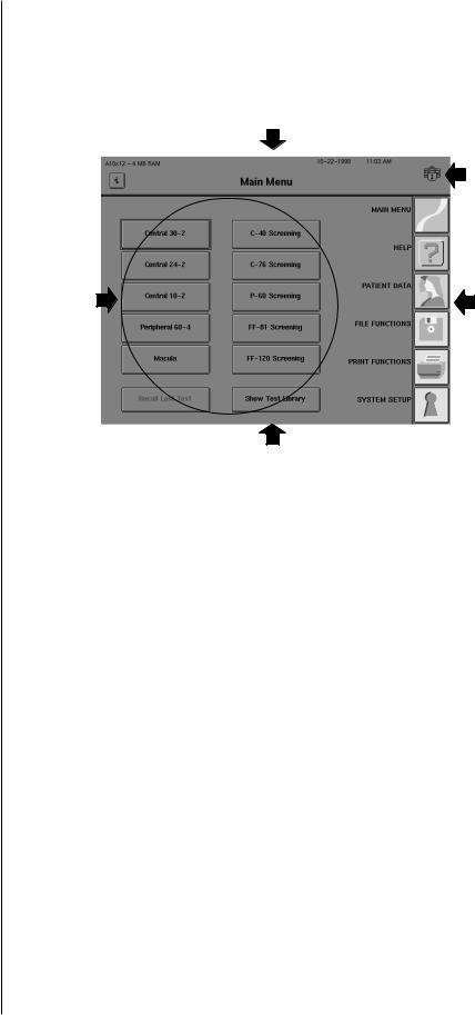
Figure 2.1: Main Areas of the HFA II Screen
The Title Bar
This area is the top portion of every screen. The middle of the title bar displays the name of the screen in bold type. The left side shows the system software version and the “i” button. More information about the “i” button appears later in this section. The right side displays the current date, time, and a picture that shows if the floppy disk in the drive is in use. Do not insert or remove a floppy disk when the padlock is displayed on the screen as shown above.
Operator messages may appear in the top right corner of the Title Bar or the center of the Screen Body to inform you of a condition or alert you to a problem. “Printer is not connected or Off Line” and “Uninitialized Disk” are examples of operator messages. Multiple messages may appear stacked and overlapping in the upper right corner. Touching the top message collapses it, revealing the previous message.
The Screen Body
The Screen Body comprises the largest part of every screen. This is where most of the commands are issued via command buttons. The contents of the Screen Body changes after every command. The Screen Body is referred to as the “screen” throughout the User’s Guide.
Frequently, a button will appear dimmed or “ghosted.” This indicates either that the button function cannot be activated from that screen or that the button represents a feature that is not available on the HFA II model being used. For example, the CUSTOM TESTS button on the model 720i HFA II has been ghosted because this option is not available on the model 720i and is, therefore, nonfunctional.
REV. B 02/03 PN 51680-1 |
HUMPHREY FIELD ANALYZER II - i series |
|
|

GENERAL OPERATION |
2-3 |
|
Icon buttons |
|
These buttons occupy the right side of most screens. Each has a unique function that can be |
|
||
|
|
accessed at any time unless there is a pop-up window present or the icon buttons are ghosted. |
|
|
See “Pop-up Windows” later in this section for details. The HFA II’s icon buttons are shown |
|
|
below along with a brief description of their function. |
|
|
MAIN MENU |
|
|
The MAIN MENU icon allows you to return to the Main Menu screen from other system screens. |
|
|
HELP |
|
|
The HELP icon gives brief explanations of certain features and procedures available on the |
|
|
HFA II. You should always consult this Guide for further information. |
|
|
PATIENT DATA |
|
|
PATIENT DATA leads you to the Patient Data screen where you may enter or recall the patient’s |
|
|
name, date of birth, I. D. number, trial lens information, and diagnostic data prior to testing. |
|
|
Main Menu test buttons also automatically lead you to the Patient Data screens. |
|
|
FILE FUNCTIONS |
|
|
Through FILE FUNCTIONS you can access the patient test results that have been saved as well |
|
|
as perform various database management procedures. |
|
|
PRINT FUNCTIONS |
|
|
PRINT FUNCTIONS allows you to print out hard copies of test results in various formats. |
|
|
SYSTEM SETUP |
|
|
SYSTEM SETUP lets you define certain user settings. Examples of these are time and date, |
|
|
printer type, visual acuity format, and practice name and address on printouts. Access to the |
|
|
SYSTEM SETUP icon is only available from the Main Menu screen. |
|
|
UNDO |
|
|
The UNDO icon takes you back to the previous screen. In some cases pressing the UNDO icon |
|
|
will appear to take you back two screens. This occurs when the previous screen is a pop-up |
|
|
window. The UNDO icon is not available on the Main Menu screen. |
|
|
|
REV. B 02/03 PN 51680-1 |
HUMPHREY FIELD ANALYZER II - i series |

2-4 |
GENERAL OPERATION |
The information |
The “i ” button is present on most screens and can be found in the upper left corner of the |
“i” button |
screen. Pressing this button brings you to the Unit Configuration screen which contains |
|
information useful when contacting Humphrey Customer Service. If the video eye monitor is |
|
displayed, you will need to turn the monitor OFF to access the “i ” button. |
|
The following information is displayed when the “i ” button is pressed: |
|
Model Number |
|
Serial Number |
|
Operating System-Revision Number |
|
Language |
|
Hardware Options |
|
Software Options |
|
Personalized Information such as user’s name, address, and telephone number. |
|
The Unit Configuration information may be printed by pressing the PRINT button. To return to |
|
the previous screen, touch CANCEL. |
|
Figure 2.2: The Unit Configuration Screen. |
Touch screen |
Operating the HFA II is literally at your fingertips. You can perform all functions, whether |
|
entering data or selecting a test, by simply touching a command button on the touch screen. |
|
While using the touch screen, the HFA II is activated when your finger is removed |
|
from the button you select. Be careful not to pound or press too hard against the |
|
touch screen. A light touch works best. An audible beep will alert you of successful button |
|
activation. |
|
If you have difficulty activating the touch screen, consider re-calibrating it. Details on |
|
calibrating the touch screen are found in “Additional Setup” later in this section as well as in |
|
Section 12: “Touch Screen Calibration”. |
REV. B 02/03 PN 51680-1 |
HUMPHREY FIELD ANALYZER II - i series |
|
|
 Loading...