


OPMI® Sensera
on S7 Suspension Systems
Instructions for use
G-30-1434-en
Issue 10.0
Printed on 30. 01. 2009

Key to symbols
Different symbols used in this manual draw your attention to safety aspects and useful tips. These symbols are explained in the following.
Warning!
The warning triangle indicates potential sources of danger which may
constitute a risk of injury for the user or a health hazard.
Caution:
The square indicates situations which may lead to malfunction, defects,
collision or damage of the instrument.
Note:
The hand indicates hints on the use of the instruments or other tips for the
user.
OPMI
®
is a registered trademark of Carl Zeiss.

Contents
– Key to symbols 2
Functions at a glance 7
– OPMI Sensera surgical microscope 8
– Illumination systems 10
– S7 floor stand 11
– S7 ceiling mount with rigid column 12
– S7 ceiling mount with lifting column 13
Safety 15
– Notes on installation and use 17
– Safety devices of the suspension system 22
– Warning labels and notes 26
Description 31
Sensera surgical microscope on S7 suspension systems 34
– Intended use 34
– Description of the system 34
– System components 36
OPMI Sensera surgical microscope 38
– Design 38
– Controls, displays, connections 40
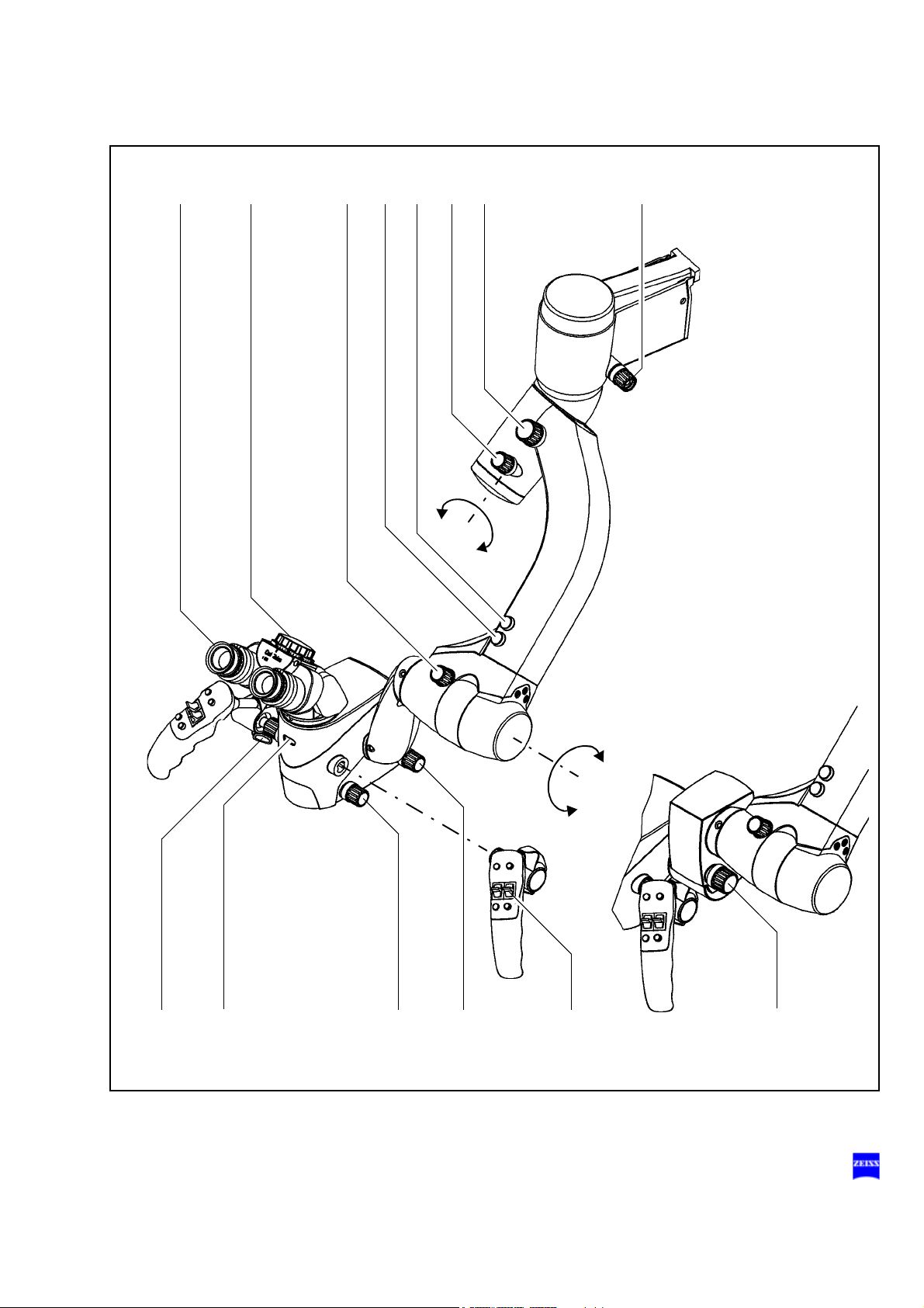
– Tiltable binocular tube and eyepieces 46
S7 floor stand 50
– Design 50
– Controls, displays, connections 52
– Suspension arm 52
– Carrier arm, stand column, stand base 54
– Connector panel of S7 floor stand 56
– Instrument tray (option) 58
S7 ceiling mount 60
G-30-1434-en OPMI® Sensera on S7 Suspension Systems Issue 10.0
Printed on 30. 01. 2009

– Design 60
– Controls, displays, connections 62
– Carrier and suspension arms 62
– Connector panel of S7 ceiling mount 64
S7 ceiling mount with lifting column 66
– Design 66
– Controls, displays, connections 68
– Ceiling flange with lifting column 68
– Carrier and suspension arms 70
– Connector panel of S7 ceiling mount with lifting column 72
Illumination system 74
– Halogen illumination system 76
– Xenon illumination system 78
Control panel and menu overview 82
– Structure of the menus 84
Foot control panel (option) 104
– Intended use 104
–Design 104
– Foot control panel with 14 functions 106
– Foot control panel with 8 functions 107
Preparations for use 109
Attaching the equipment 112
– Mounting the tube and eyepieces 112
Connections 114
– Connecting the strain relief device 114
– Connecting the suspension system - S7 floor stand 116
– Connecting the suspension system - S7 ceiling mount with
rigid column 118
– Connecting the suspension system - S7 ceiling mount with
lifting column 120
– Connecting video monitor and MediLive ImageBox (option) 122
Adjusting the system - S7 floor stand 124
– Balancing the suspension arm 124
– Setting the limit of downward travel of the suspension arm 124
G-30-1434-en OPMI® Sensera on S7 Suspension Systems Issue 10.0
Printed on 30. 01. 2009

Adjusting the system - S7 ceiling mount with rigid column 126
– Balancing the suspension arm 126
– Setting the limit of downward travel of the suspension arm 126
Adjusting the system - S7 ceiling mount with lifting column 128
– Setting an ergonomic working height 128
– Balancing the suspension arm (ceiling mount with lifting column) 130
– Setting the limit of downward travel of the suspension arm 130
Balancing the surgical microscope 132
Surgical microscope with a laser micromanipulator 136
Adjusting the surgical microscope 138
Configuring the camera settings (config) 139
Configuring Image Capture 144
Relocating the S7 floor stand 152
Operation 155
Checklist for S7 floor stand 156
Checklist for S7 ceiling mount with rigid column 160
Checklist for S7 ceiling mount with lifting column 164
Procedure 168
– Working with the SpeedFokus autofocus option 169
– Display and deletion of images (USB option) 170
What to do in an emergency 172
– Failure of the focusing function 172
– Failure of the zoom function 174
– Failure of the halogen lamp 176
– Lamp failure of the xenon illumination 178
– Failure of the SpeedFokus autofocus option 182
Maintenance / Further information 183
– Trouble-shooting 184
– Replacing the halogen lamp 190
– Changing the xenon lamp module 194
– Magnifications / Fields of view 198
– Care of the unit 200
– Cleaning optical surfaces 200
G-30-1434-en OPMI® Sensera on S7 Suspension Systems Issue 10.0
Printed on 30. 01. 2009

– Auxiliaries from Zeiss 201
– Cleaning mechanical surfaces 201
– Sterilization 201
– Disinfecting the control keys 203
– Ordering data 204
– Spare parts 207
– Accessories 209
– Disposal 210
Technical data 211
– Technical data 212
– Integrated 1 CCD PAL video camera (option) 219
– Integrated 1 CCD NTSC video camera (option) 219
– Ambient requirements 220
– Changes to the system 220
Index 221
G-30-1434-en OPMI® Sensera on S7 Suspension Systems Issue 10.0
Printed on 30. 01. 2009

Functions at a glance 7
Functions at a glance
OPMI Sensera surgical microscope 8
Illumination systems 10
S7 floor stand 11
S7 ceiling mount with rigid column 12
S7 ceiling mount with lifting column 13
G-30-1434-en OPMI® Sensera on S7 Suspension Systems Issue 10.0
Printed on 30. 01. 2009

8 Functions at a glance
OPMI Sensera surgical microscope
1 Adjusting the eyecup and the prescription Pages 36/87
2 Adjusting the interpupillary distance Page 34
3 Manually adjusting the friction of the front-to-back tilt Page 84
4 Motorized adjustment of tilt axis B
(microscope tilts downward) Page 84
5 Motorized adjustment of tilt axis B
(microscope tilts upward) Page 84
6 Manually adjusting the friction of lateral tilt axis A Page 82
7 Manually adjusting the balance of lateral tilt axis A Page 82
8 Manually adjusting the friction of the microscope's
axis of rotation
9 Locking the handgrip in a convenient position Page 32
10 Manually adjusting zoom (emergency mode) Pages 30/98
11 Manual focusing Pages 30/96
12 Adjusting the spot illumination Page 30
13 Triggering motorized microscope functions Page 32
14 External focus (option) Page 30
Page 82
G-30-1434-en OPMI® Sensera on S7 Suspension Systems Issue 10.0
Printed on 30. 01. 2009
Functions at a glance 9
12 3
45 67
10 11 129
8
13
A
B
14
G-30-1434-en OPMI® Sensera on S7 Suspension Systems Issue 10.0
Printed on 30. 01. 2009

10 Functions at a glance
124 8753 96
Illumination systems
Halogen illumination system
1 Closed flap: main lamp is on - Open flap: backup lamp
is on
2 Selecting a filter page 76
3 Opening the lamp module page 76
4 Manual activation of the backup lamp page 76
Xenon illumination system
5 Selecting a filter page 78
6 Resetting the counter page 80
7 Manual activation of the backup lamp page 78
8 Opening the lamp module page 78
9 Red segment is lit - backup lamp is in use page 78
page 76
G-30-1434-en OPMI® Sensera on S7 Suspension Systems Issue 10.0
Printed on 30. 01. 2009

S7 floor stand
12
13
18
17
16
15
14
11
10
9
S
7
Functions at a glance 11
9 Lamp housing with halogen or xenon illumination Page 40
10 Control panel Page 54
11 Maneuvering handle with hooks on which to hang the
Page 88
foot control panel
12 Connector panel Page 46
13 Casters with locking tabs (4 x) Page 44
14 Adjusting the friction of the carrier arm's swivel
Page 44
movement
15 Adjusting the friction of the suspension arm's
Page 44
swivel movement
16 Balancing the suspension arm Page 80
17 Adjusting the limit of downward travel Page 80
18 Adjusting the friction of upward/downward movement Page 42
G-30-1434-en OPMI® Sensera on S7 Suspension Systems Issue 10.0
Printed on 30. 01. 2009

12 Functions at a glance
9
10
11
12
13 14 15
16 17
S7 ceiling mount with rigid column
9 Control panel Page 50
10 Power switch Page 50
11 Connector panel Page 44
12 Lamp housing with halogen or xenon illumination Page 46
13 Balancing the suspension arm Page 78
14 Adjusting the limit of downward travel Page 78
15 Adjusting the friction of upward/downward movement Page 42
16 Adjusting the friction of the suspension arm's
swivel movement
17 Adjusting the friction of the carrier arm's swivel
movement
Page 42
Page 42
G-30-1434-en OPMI® Sensera on S7 Suspension Systems Issue 10.0
Printed on 30. 01. 2009

Functions at a glance 13
16
9
12
18
17
10
11
13 14 15
S7 ceiling mount with lifting column
9 Control panel page 82
10 Power switch page 82
11 Connector panel page 72
12 Lamp housing with halogen or xenon illumination page 74
13 Balancing the suspension arm page 130
14 Adjusting the limit of downward travel page 130
15 Adjusting the friction of upward/downward movement page 62
16 Lifting/lowering the lifting column page 68
17 Adjusting the friction of the carrier arm's swivel
movement
18 Adjusting the friction of the suspension arm's
swivel movement
page 62
page 62
G-30-1434-en OPMI® Sensera on S7 Suspension Systems Issue 10.0
Printed on 30. 01. 2009

14 Functions at a glance
G-30-1434-en OPMI® Sensera on S7 Suspension Systems Issue 10.0
Printed on 30. 01. 2009

Safety
Safety 15
Notes on installation and use 17
Safety devices of the suspension system 22
Warning labels and notes 26
G-30-1434-en OPMI® Sensera on S7 Suspension Systems Issue 10.0
Printed on 30. 01. 2009

16 Safety
The device described in this manual has been designed and tested in accordance with Carl Zeiss safety standards as well as German and international standards. This guarantees a high degree of instrument safety.
The system described in this user manual has been designed in compliance with the requirements of:
–EN –IEC –UL –CSA
In accordance with Directive 93/42/EEC for medical devices, the complete quality management system of the company Carl Zeiss Surgical
GmbH, 73446 Oberkochen, Germany, has been certified by DQS Deutsche Gesellschaft zur Zertifizierung von Managementsystemen GmbH, a
notified body, under registration number 250758 MP23.
– As per Directive 93/42/EEC, the unit is a Class I instrument.
– For USA: FDA classification Class I.
We would like to provide you with information about safety aspects which
must be observed when handling this device. This chapter contains a
summary of the most important information concerning matters relevant
to instrument safety.
Important safety information has been incorporated in this manual and is
marked with a warning triangle accordingly. Please give this information
your special attention.
The correct use of the system is absolutely vital for safe operation. Please
make yourself totally familiar with the contents of this manual prior to startup of the instrument. Please also observe the user manuals of any additional equipment. Further information is available from our service department or from authorized representatives.
• Please observe all applicable accident prevention regulations.
• The instrument must be connected to a special emergency backup
line supply in accordance with the regulations or directives which apply in your country.
G-30-1434-en OPMI® Sensera on S7 Suspension Systems Issue 10.0
Printed on 30. 01. 2009

Safety 17
Notes on installation and use
Safe working order
• Do not operate the equipment contained in the delivery package in
– explosion-risk areas,
– the presence of inflammable anesthetics or volatile solvents such
as alcohol, benzine or similar chemicals.
• Do not station or use the instrument in damp rooms. Do not expose
the instrument to water splashes, dripping water or sprayed water.
• Immediately unplug any equipment that gives off smoke, sparks or
strange noises. Do not use the instrument until our service representative has repaired it.
• Do not place any fluid-filled containers on top of the instrument. Make
sure that no fluids can seep into the instrument.
• Do not force cable connections. If the male and female parts do not
readily connect, make sure that they are appropriate for one another.
If any of the connectors are damaged, have our service representative
repair them.
• Potential equalization: If requested, the instrument can be incorporated into potential equalization measures.
• Do not use a mobile phone in the vicinity of the equipment because
the radio interference can cause the equipment to malfunction. The effects of radio interference on medical equipment depend on a number
of various factors and are therefore entirely unforeseeable.
• Modifications and repairs on these instruments or instruments used
with them may only be performed by our service representative or by
other authorized persons.
• The manufacturer will not accept any liability for damage caused by
unauthorized persons tampering with the instrument; this will also forfeit any rights to claim under warranty.
• Over longer distances (e.g. removal, return for repair, etc), the instrument may only be transported in the original packaging or in special
return packaging. Please contact your dealer or the Carl Zeiss service
team.
• Use this instrument only for the applications described.
G-30-1434-en OPMI® Sensera on S7 Suspension Systems Issue 10.0
Printed on 30. 01. 2009

18 Safety
• Only use the instrument with the accessories supplied. Should you
wish to use other accessory equipment, make sure that Carl Zeiss or
the equipment manufacturer has certified that its use will not impair
the safety of instrument.
• Only personnel who have undergone training and instruction are allowed to use this instrument. It is the responsibility of the customer or
institution operating the equipment to train and instruct all staff using
the equipment.
• Keep the user's manuals where they are easily accessible at all times
for the persons operating the instrument.
• Never look at the sun through the binocular tube, the objective lens or
an eyepiece.
• Do not pull at the light guide cable, at the power cord or at other cable
connections.
• This instrument is a high-grade technological product. To ensure optimum performance and safe working order of the instrument, its safety
must be checked once every 12 months. We recommend having this
check performed by our service representative as part of regular maintenance work.
If a failure occurs which you cannot correct using the trouble-shooting
table, attach a sign to the instrument stating it is out of order and contact our service representative.
Warning!
Do not use the video images for diagnostic purposes, as the video cameras and the monitor have not been calibrated. The visualized images
may therefore include deviations in shape, contrast and color.
• Observe the labels showing the symbol "Risk of crushing“!
Notes on EMC (Electromagnetic Compatibility)
The device complies with the EMC requirements of IEC 60601-1-2. For
operating the device, observe the EMC precautions specified below.
Only use spare parts approved by Carl Zeiss for this device.
Do not use any portable or mobile HF communication equipment in the
vicinity of the device, as it cannot be ruled out that the function of the device will be impaired.
G-30-1434-en OPMI® Sensera on S7 Suspension Systems Issue 10.0
Printed on 30. 01. 2009

Safety 19
Requirements for operation
• For ceiling mounts only: Our service staff or a qualified person appointed by us will install the system on ceiling anchors which have
been properly mounted by the construction engineers responsible.
These ceiling anchors must comply with the specifications contained
in our planning manual.
Our service representative or a specialist authorized by us will install the
instrument. Please make sure that the following requirements for operation remain fulfilled in the future:
– All mechanical connections (details in the user's manual) which are
relevant to safety are properly connected and screw connections tightened.
– All cables and plugs are in good working condition.
– The voltage setting on the instrument conforms to the rated voltage of
the line supply on site.
– The instrument is plugged into a power outlet which has a properly
connected protective ground contact.
– The power cord being used is the one designed for use with this in-
strument.
Before every use and after re-equipping the instrument
• Make sure that all ”Requirements for operation” are fulfilled.
• Go through the checklist.
• Re-attach or close any covers, panels or caps which have been removed or opened.
• Pay special attention to warning symbols on the instrument (triangular
warning signs with exclamation marks), labels and any parts such as
screws or surfaces painted red.
• Do not cover any ventilation openings.
For every use of the instrument
General
• Never operate the system unattended.
• Avoid looking directly into the light source, e.g. into the microscope objective lens or a light guide.
• When the illumination is on, the light guide must be connected at both
ends. Otherwise there is a risk of fire or burn injuries.
G-30-1434-en OPMI® Sensera on S7 Suspension Systems Issue 10.0
Printed on 30. 01. 2009

20 Safety
• Make sure that the instrument has been switched off before you
change the xenon lamp module. When switched on, the ignition system generates high voltage.
• The xenon illumination system is a high-intensity light source which if used improperly - can cause thermal injury to skin or tissue. Keep
the exposed tissue moist and provide sufficient irrigation. Carefully
monitor the effects of the illumination on the tissue, in particular in the
following cases:
– during prolonged procedures on skin and tissue using objective
– during procedures on tissue with a low blood supply,
– with high brightness settings of the xenon lamp.
• Since the xenon lamp provides high light intensity and generates light
with a spectrum similar to daylight, it must not be used for ophthalmic
applications.
lenses with a short focal length (short working distance),
• Any kind of radiation has a detrimental effect on biological tissue.This
also applies to the light illuminating the surgical field. Please therefore
reduce the brightness and duration of illumination on the surgical field
to the absolute minimum required.
S7 floor stand
• Using the brake tabs on the base, secure the stand in position. Make
sure that the stand is stable and cannot roll away.
S7 ceiling mount with lifting column
• The lifting column is used to move the microscope into position for sur-
gery prior to the surgical procedure.
Do not constantly move the lifting column up and down, since a thermal cut-out will then automatically switch off the drive motor. If this occurs, the lifting column cannot be moved again until the motor has
cooled down.
After every use of the instrument
• Always use the main power switch of the instrument to turn it off.
• The main power switch must always be turned off when the instrument
is not in use.
G-30-1434-en OPMI® Sensera on S7 Suspension Systems Issue 10.0
Printed on 30. 01. 2009

Safety 21
G-30-1434-en OPMI® Sensera on S7 Suspension Systems Issue 10.0
Printed on 30. 01. 2009

22 Safety
12
Safety devices of the suspension system
Lifting column
Selector switch
for setting the optimum viewing height of the surgical microscope or for
downward movement into the working position.
As long as you keep the selector switch in the turned position, the lifting
column moves upward (2) or downward (1), depending on the switch position. When you release the selector switch, the lifting column stops immediately.
The switching technology causes a delay of approx. 2 seconds at the
upper and lower end positions of the lifting column. After this time, you
can move the column in the opposite direction again by activating the selector switch.
– Before raising or lowering the suspension system, make sure that
there is sufficient clearance from other objects so that any collision is
avoided.
Warning!
– Do not
– Do not
– Make sure that the patient is not
adjustment of the lifting column.
activate the lifting column during surgery!
use the lifting column for focusing.
put at risk or injured by the motorized
G-30-1434-en OPMI® Sensera on S7 Suspension Systems Issue 10.0
Printed on 30. 01. 2009

Safety 23
1
2
Halogen illumination system
1 Manual switching to the backup lamp
The lamp housing contains a backup lamp which is automatically
swung into the illumination beam path when the first lamp fails. If this
automatic function fails, you can switch on the backup lamp by
pressing this button.
2 GG 475 retina protection filter
The filter selector knob has four positions:
0 no filter
1 GG 475 filter: to protect the patient's eye during treatment
against unnecessary (blue) radiation (retinal injury).
2 KK 40 filter: to increase color temperature
3 no filter
G-30-1434-en OPMI® Sensera on S7 Suspension Systems Issue 10.0
Printed on 30. 01. 2009

24 Safety
Xenon illumination system
Warning!
The xenon lamp has a limited service life of 500 h.
If used beyond its maximum service life, the xenon lamp may explode.
Change the xenon lamp in good time.
Warning!
Lamp rupture (audible as a loud bang) may lead to jamming of the lamp
module and/or failure of the electronics modules.
• Before opening the lamp housing, make sure that the system is moved
to a position where neither the patient nor the user is put at risk by falling items.
• Do not continue using the system if the lamp module is jammed or the
illumination is no longer operational due to defective electronics modules. Inform our service department.
1 Switching to the backup lamp
The lamp module contains two xenon lamps. The second lamp is used
as a backup lamp which has to be swung into the illumination beam
path when the first lamp fails.
If the xenon lamp fails, open the lamp module as follows:
Press button (3). The lamp module is slightly ejected. Pull out the lamp
module as far as it will go. Turn knob (1) through 180° until it snaps in.
This moves the backup lamp into the illumination beam path. Push the
lamp module all the way back into the lamp housing.
2 Indicator: backup lamp is in use
When the red segment in knob (1) lights up, the backup lamp is in use.
Note:
If the first lamp has failed and the backup lamp is in use, make sure to
have a backup lamp module ready at hand as a precaution.
G-30-1434-en OPMI® Sensera on S7 Suspension Systems Issue 10.0
Printed on 30. 01. 2009

Safety 25
3
1
2
2
G-30-1434-en OPMI® Sensera on S7 Suspension Systems Issue 10.0
Printed on 30. 01. 2009

26 Safety
000000-0000-000
OPMI® Sensera
1
2
Warning labels and notes
Caution:
Observe all warning labels and notes!
If any label is missing on your instrument or has become illegible, please
contact us or one of our authorized representatives. We will supply the
missing labels.
G-30-1434-en OPMI® Sensera on S7 Suspension Systems Issue 10.0
Printed on 30. 01. 2009

Safety 27
14
- Balance +
176164
G-30-1434-en OPMI® Sensera on S7 Suspension Systems Issue 10.0
Printed on 30. 01. 2009

28 Safety
S7 floor stand with instrument tray option
G-30-1434-en OPMI® Sensera on S7 Suspension Systems Issue 10.0
Printed on 30. 01. 2009

Safety 29
- Balance +
14
176164
G-30-1434-en OPMI® Sensera on S7 Suspension Systems Issue 10.0
Printed on 30. 01. 2009

30 Safety
14
- Balance +
176164
G-30-1434-en OPMI® Sensera on S7 Suspension Systems Issue 10.0
Printed on 30. 01. 2009

Description
Description 31
Sensera surgical microscope on S7 suspension systems 34
Intended use 34
Description of the system 34
System components 36
OPMI Sensera surgical microscope 38
Design 38
Controls, displays, connections 40
Tiltable binocular tube and eyepieces 46
S7 floor stand 50
Design 50
Controls, displays, connections 52
Suspension arm 52
Carrier arm, stand column, stand base 54
Connector panel of S7 floor stand 56
Instrument tray (option) 58
S7 ceiling mount 60
Design 60
Controls, displays, connections 62
Carrier and suspension arms 62
Connector panel of S7 ceiling mount 64
S7 ceiling mount with lifting column 66
Design 66
Controls, displays, connections 68
Ceiling flange with lifting column 68
Carrier and suspension arms 70
Connector panel of S7 ceiling mount with lifting column 72
G-30-1434-en OPMI® Sensera on S7 Suspension Systems Issue 10.0
Printed on 30. 01. 2009

32 Description
Illumination system 74
Halogen illumination system 76
Xenon illumination system 78
Control panel and menu overview 82
Structure of the menus 84
Foot control panel (option) 104
Intended use 104
Design 104
Foot control panel with 14 functions 106
Foot control panel with 8 functions 107
G-30-1434-en OPMI® Sensera on S7 Suspension Systems Issue 10.0
Printed on 30. 01. 2009

Description 33
G-30-1434-en OPMI® Sensera on S7 Suspension Systems Issue 10.0
Printed on 30. 01. 2009

34 Description
Sensera surgical microscope on S7 suspension systems
Intended use
The OPMI Sensera surgical microscope on S7 suspension systems has
been specially designed for use in ENT surgery, i.e. the overall system
meets the special requirements of this discipline.
The system is intended for use in hospitals, clinics or other human medicine institutions.
The system must only be operated by physicians, nurses and other OR
staff who have undergone appropriate training and observe the instructions of the user's manual. The installation conditions and the use of the
system must meet microsurgical requirements:
– low vibration
– clean environment
– avoidance of extreme mechanical stress.
Description of the system
The apochromatic optics of the microscope provide superb optical quality.
The microscope image displays optimum contrast and excellent detail
recognition along with outstanding depth of field and maximum 3D perception. The 1:6 ratio zoom system allows the magnification of the overall
system to be set as required by the surgical procedure.
You can use the surgical microscope with or without an integrated video
camera. Depending on your requirements, you can choose between a
PAL or an NTSC video system.
Suspension systems
The S7 floor stand is a suspension system for Zeiss surgical micro-
scopes. It comprises a suspension arm, a carrier arm, a stand column and
a stand base.
A maneuvering handle attached to the stand column is used to move the
stand and to attach the foot control panel. The stand column is provided
on its left and right with cable supports for winding up cables before the
unit is relocated.
G-30-1434-en OPMI® Sensera on S7 Suspension Systems Issue 10.0
Printed on 30. 01. 2009

Description 35
The stand base is extremely easy to move on its four casters. It has been
designed in such a way that high stability is ensured even with unfavorable loading of the stand. The locking tabs permit you to reliably secure
the floor stand in position at the site of use.
Note:
As the stand is very easy to maneuver, there is a tendency to underestimate its weight. Therefore, move the stand slowly and carefully!
The S7 ceiling mount with rigid column is a suspension system for
Zeiss surgical microscopes. It comprises a suspension arm, a carrier arm,
a ceiling column and a ceiling flange.
The S7 ceiling mount with lifting column is a suspension system for
Zeiss surgical microscopes. It comprises a suspension arm, a carrier arm,
a ceiling flange and a lifting column. This motorized lifting column permits
the viewing height to be perfectly matched to the surgeon's requirements.
The carrier arm of all suspension systems contains the control unit with all
electrical supply systems required for the control of a motorized surgical
microscope. You can control the motorized functions using the handgrips,
or via a foot control panel (option). A light guide (fiber optic illumination)
directs the light from the lamp housing in the suspension system to the
surgical microscope.
The suspension arm of all types of suspension system permits almost effortless positioning of the surgical microscope. The spring force of the
suspension arm can be varied in a range from 6 to 14 kg, permitting reliable balancing of the microscope even with accessory equipment attached. The downward movement of the suspension arm can be limited
using an adjustable positioning aid.
A control panel allows the adjustment of user-defined settings such as the
zoom, focus, brightness and video settings, and the programming of the
configurable handgrip buttons.
The SpeedFokus autofocus option permits you to select features (ROI, region of interest) in the image of the surgical field and to rapidly focus on
them automatically or at the press of a button.
USB memory option
An optional USB port permits you to save image data in the JPEG or TIFF
format on a USB memory stick. Image data can also be read from a USB
memory stick and displayed on a connected monitor. The saved image
data can also be deleted.
Warning!
If the xenon light source is used, the unit must not be used in ophthalmic
applications. Severe injury to the patient's eye is possible.
G-30-1434-en OPMI® Sensera on S7 Suspension Systems Issue 10.0
Printed on 30. 01. 2009

36 Description
System components
1 S7 ceiling mount with lifting column
2 S7 ceiling mount
3 S7 floor stand
4 OPMI Sensera surgical microscope
with 180° tiltable tube and magnetic eyepieces
Note:
The overall system comprises a suspension system and a microscope. All options described in this user manual can be ordered separately.
G-30-1434-en OPMI® Sensera on S7 Suspension Systems Issue 10.0
Printed on 30. 01. 2009

Description 37
1
2
3
4
G-30-1434-en OPMI® Sensera on S7 Suspension Systems Issue 10.0
Printed on 30. 01. 2009

38 Description
OPMI Sensera surgical microscope
Design
The Sensera surgical microscope comprises the following modules:
1 Microscope body
The apochromatic optics of the microscope provide superb optical
quality. The microscope image displays optimum contrast and excellent detail recognition along with outstanding depth of field and maximum 3D perception. The 1:6 ratio zoom system allows the magnification of the overall system to be set as required by the surgical
procedure. Using the integrated variable focusing optics (Varioskop),
you can adjust the working distance between 200 mm and 415 mm as
required.
2 Support arm for the surgical microscope
3 Balancing system
This system allows almost effortless balancing of the surgical microscope.
4 Axis of microscope rotation
5 Coupling
for mounting the surgical microscope on the suspension system.
6 Handgrips
for moving the surgical microscope. Using the buttons on the handgrips, you can control important functions (e.g. focusing, zooming,
brightness, still/video camera release).
Warning!
To permit almost effortless guidance of the surgical microscope, the microscope and the suspension system used must be correctly balanced.
If the system is in an extremely unbalanced state, the unit can move uncontrollably out of position. For this reason, hold the surgical microscope
tightly at its handgrips before loosening the friction adjustment screw (see
page 52) on the suspension arm.
7 Motorized fine focusing (option),
recommended for the use of OPMI Sensera with laser micromanipulators.
G-30-1434-en OPMI® Sensera on S7 Suspension Systems Issue 10.0
Printed on 30. 01. 2009

Description 39
1
524
6
7
2
3
G-30-1434-en OPMI® Sensera on S7 Suspension Systems Issue 10.0
Printed on 30. 01. 2009

40 Description
2
1
Zero position
Controls, displays, connections
1 Friction adjustment for vertical axis
Use this knob to adjust the friction for the vertical axis as required.
2 Balance setting of the lateral tilt motion
Use this knob to adjust the balance setting of the lateral tilt motion.
3 Adjusting the friction of the lateral tilt axis
Use this knob to adjust the friction for the lateral tilt axis as required.
4 Balance setting of the front-to-back tilt motion
When you press this button, the microscope slowly tilts upward
5 Balance setting of the front-to-back tilt motion
When you press this button, the microscope slowly tilts downward
6 Adjusting the friction of the front-to-back tilt axis
Use this knob to adjust the friction for the front-to-back tilt axis as required.
.
.
7 Marking for zero position
In the zero position, the microscope body is decoupled from the suspension (see "Balancing the front-to-back tilt motion").
G-30-1434-en OPMI® Sensera on S7 Suspension Systems Issue 10.0
Printed on 30. 01. 2009

Description 41
1
3
4
2
5
1
2
2
1
6
7
G-30-1434-en OPMI® Sensera on S7 Suspension Systems Issue 10.0
Printed on 30. 01. 2009

42 Description
8 Dust cover
9 Handgrips (removable)
for moving the surgical microscope and triggering the motorized OPMI
functions (see points 14 to 17).
10 Locking screw
for optimum positioning of the handgrips.
11 Zoom wheel (emergency operation)
If the motorized functions fail, you can manually adjust the magnification after removing the plastic cover from the zoom wheel.
12 Focusing knob
for manual adjustment of the image definition (focus, working distance).
13 Spot illumination knob
for continuous adjustment of the illuminated field diameter.
14 Focusing knob for use of a laser micromanipulator (option)
for manual adjustment of the image definition (focus) when a laser micromanipulator is used.
G-30-1434-en OPMI® Sensera on S7 Suspension Systems Issue 10.0
Printed on 30. 01. 2009

Description 43
911 1310 12
8
14
G-30-1434-en OPMI® Sensera on S7 Suspension Systems Issue 10.0
Printed on 30. 01. 2009

44 Description
Z
F
15 Release buttons, freely programmable
In combination with an S7 suspension system, specific functions of the
suspension system can be assigned to these buttons (e. g.: focus,
zoom, brightness control, still and video camera release, etc.). Configuring these buttons is described on page 91 (Handgrip Settings
menu).
The default setting is brightness control.
16 Zoom rocker switch
for adjusting the magnification factor γ from 0.4x to 2.4x.
17 Focus rocker switch
for continuous focusing within the working distance of 200 to 415 mm.
The maximum value achievable can only be set manually.
Note:
18 Release buttons, freely programmable
In combination with an S7 suspension system, specific functions of the
suspension system can be assigned to these buttons (e. g.: focus,
zoom, brightness control, still and video camera release, etc.). Configuring these buttons is described in chapter "Description/Structure of
the menus".
19 Locking the handgrips in position
Using this locking device, you can lock each handgrip in different positions.
20 Knurled nut
for removing the handgrips.
21 Knobs instead of handgrips
After removing the handgrips, mount the knobs supplied to protect the
connector contacts and to be able to guide the surgical microscope.
These knobs can be provided with sterile caps.
22 Labeling fields
Labeling fields are provided for the freely programmable handgrip buttons. On delivery, you receive a labeling set (small stickers) for each
handgrip, permitting you to label the handgrips in accordance with
your specific button assignment.
The labeling set includes not only stickers with abbreviations for the
functions provided, but also with the letters A, B, C and D.
If several users with different button configurations are working on the
system, operating errors can be avoided by labeling the freely programmable buttons with A, B, C, D or E instead of specific functions,
i.e. by using the same designations for the buttons as in the description of the menus, see from page 91.
G-30-1434-en OPMI® Sensera on S7 Suspension Systems Issue 10.0
Printed on 30. 01. 2009

15
17
18
16
19
F
Z
20
21
F
Z
22
Description 45
G-30-1434-en OPMI® Sensera on S7 Suspension Systems Issue 10.0
Printed on 30. 01. 2009

46 Description
Tiltable binocular tube and eyepieces
180° tiltable tube
1 PD adjustment knob
The correct position has been set when the two eyepiece images
merge into one.
2 180° tiltable tube
3 Eyepiece tube
G-30-1434-en OPMI® Sensera on S7 Suspension Systems Issue 10.0
Printed on 30. 01. 2009

Description 47
1
2
3
G-30-1434-en OPMI® Sensera on S7 Suspension Systems Issue 10.0
Printed on 30. 01. 2009

48 Description
Widefield eyepieces with magnetic coupling
Note:
When you remove these eyepieces from the tube, please note that they
are fitted with a magnetic coupling. When mounted, the eyepieces display
a very weak magnetic field, so that the usual rules for the handling of magnets must only be observed with eyepieces which have not been mounted
on the microscope:
• Do not place the eyepieces close to instruments where there is any
risk of magnetization.
• Do not place the eyepieces on sensitive electronic units such as infusion pumps, cardiac pace-makers, measuring instruments or magnetic data carriers such as disks, audiotapes and videotapes, or credit
cards.
• Always store eyepieces not used in their original packaging.
1 Eyecup
Always adjust the eyecups in such a way that you can see the full field
of view.
– Viewing with eyeglasses: Screw in the eyecups all the way.
– Viewing without eyeglasses: Screw out the eyecups until you
see the full field of view.
2 Diopter adjustment ring
The eyepieces provide ametropia compensation between -8 D and
+5 D. Eyeglass wearers who perform surgery wearing their glasses
set the diopter adjustment ring to 0 D. Turn the ring until you have obtained the optimum setting. An integrated brake holds the ring in the
position set.
3 Diopter scale
for reading the prescription set.
G-30-1434-en OPMI® Sensera on S7 Suspension Systems Issue 10.0
Printed on 30. 01. 2009

Description 49
1
2
3
G-30-1434-en OPMI® Sensera on S7 Suspension Systems Issue 10.0
Printed on 30. 01. 2009

50 Description
S7 floor stand
Design
1 Suspension arm
2 Lamp housing (either xenon or halogen illumination)
3 Carrier arm
4 Control panel
5 Connector panel
6 Maneuvering handle
7 Cable supports (2x, on the right and left of the stand column)
8 Stand column
9 Stand base
G-30-1434-en OPMI® Sensera on S7 Suspension Systems Issue 10.0
Printed on 30. 01. 2009

Description 51
1
2
3
4
5
6
7
8
9
S
7
G-30-1434-en OPMI® Sensera on S7 Suspension Systems Issue 10.0
Printed on 30. 01. 2009

52 Description
-
Balance
+
Controls, displays, connections
Suspension arm
1 Lamp housing with halogen or xenon illumination
The suspension system is equipped with an illumination system for
light guides. Each lamp housing contains a backup lamp. When a halogen illumination system is used, the backup lamp will be automatically swung in if the first lamp fails. When a xenon illumination system is
used, you must manually swing the backup lamp into the beam path if
the first lamp fails.
2 Friction adjustment
Knob for adjusting the friction of the suspension arm's upward/downward movement.
3 Locking lever for limiting the arm's downward movement
You can limit the downward movement of the suspension arm by adjusting a stop.
Adjustment range: from the horizontal position of the suspension arm
to its lower stop.
4 Balance setting
Knob for setting the spring force for balancing. After mounting the surgical microscope including all accessories, balance the suspension
arm using this screw. The balance setting procedure is described in
the chapter “Preparations for use/Adjusting the system“.
G-30-1434-en OPMI® Sensera on S7 Suspension Systems Issue 10.0
Printed on 30. 01. 2009

Description 53
1
2
3
4
G-30-1434-en OPMI® Sensera on S7 Suspension Systems Issue 10.0
Printed on 30. 01. 2009

54 Description
Carrier arm, stand column, stand base
1 Control and display panel
The control and display panel permits you to control all electrical functions of the S7 floor stand and the surgical microscope.
2 Friction adjustment
Knob for adjusting the friction of the carrier arm's swivel movement.
3 Handle
for moving the floor stand. Before relocating the stand, you can hang
the foot control panel and wind up the cables on the lower end of the
handle.
4 Connector panel
for connecting the unit to line power. Further connectors are provided
for powering peripheral equipment. A foot control panel can be connected to a multi-point connector.
5 Friction adjustment
Knob for adjusting the friction of the suspension arm's swivel movement.
6 Cable support
for winding up the power cord and the cable of the foot control panel.
7 Support for foot control panel
8 Locking tab
for steerable caster (4 casters are provided).
To secure the stand in position, press down at least two locking tabs.
Press down to lock the caster.
Press up to release the caster.
9 Steerable caster
The four casters roll very smoothly, permitting the unit to be easily
wheeled to the site of use.
G-30-1434-en OPMI® Sensera on S7 Suspension Systems Issue 10.0
Printed on 30. 01. 2009

Description 55
1
2
3
4
5
6
7
8
9
G-30-1434-en OPMI® Sensera on S7 Suspension Systems Issue 10.0
Printed on 30. 01. 2009

56 Description
Connector panel of S7 floor stand
1 Opening for the system cable of an external video camera
2 Remote control socket
for controlling MediLive ImageBox, MediLive MindStream or other external devices with a maximum breaking capacity of 24V/0.5A.
3 Strain relief device
The strain relief device prevents inadvertent unplugging of the following electrical connections:
– power cable,
– video connection cable,
cable for the foot control panel (option).
4 Connector for control component (option)
Here, a foot control panel can be connected.
Warning!
Please observe the maximum current consumption of power outlet
socket (5). Only connect medical devices approved by Carl Zeiss to
this outlet. When using other instruments, make sure that safety is
guaranteed regarding admissible ground leakage currents. The admissible limit value of the ground leakage current present in the suspension system's power cord must not exceed 500 µA in compliance
with EN 60601-1/IEC 60601-1. CSA/US certification in compliance
with UL 60601-1 only allows a maximum ground leakage current of
300 µA.
5 Power outlet socket
for medical devices with a maximum current consumption of 5 A.
Warning!
The current of this power outlet socket cannot
power switch.
6 Power inlet socket
Connectors for USB option
7 USB socket for USB memory stick
Note:
Only use sticks conforming to the USB-2.0 specification.
be switched off with the
8 DV output port (FireWire)
Digital, compressed video signal for recording on a digital video recorder or PC.
G-30-1434-en OPMI® Sensera on S7 Suspension Systems Issue 10.0
Printed on 30. 01. 2009

Description 57
1423569 1112107, 8
9 BNC video port (option)
for VBS video signal output
10 Y/C video port (option)
for S-VHS video signal output
11 Potential equalization pin
12 Indicator window for rated voltage
The voltage shown here must correspond to the rated line voltage provided on the site of installation. You can adjust the sliding switch using
a suitable tool.
G-30-1434-en OPMI® Sensera on S7 Suspension Systems Issue 10.0
Printed on 30. 01. 2009

58 Description
Instrument tray (option)
The S7 floor stand can be equipped or retrofitted with an instrument tray
(1). In the case of retrofitting, our service staff or an authorized person will
mount the instrument tray on your stand.
The maximum load on instrument tray (1) must not exceed 13 kg! The tray
has been designed, for example, for mounting MediLive Trio from Zeiss:
– MediLive Trio is secured on the instrument tray using two stud bolts.
– A second MediLive Trio or other accessory equipment can be mount-
ed on the instrument tray using the strap provided. Please note the instrument tray's maximum load capacity of 13 kg.
Warning!
• Make sure that the accessory equipment is positioned as securely as
possible on the instrument tray.
• Mount MediLive Trio on the instrument tray using the two stud bolts.
• If required, secure further accessory equipment on the tray using the
strap provided.
• Do not
• Remember there is a risk of collision and crushing when suspension
arm (2) is folded to its moving position. A "Risk of crushing" warning
label is therefore attached on the left and right of suspension arm (2).
• Please read the relevant user manual before starting up the accessory
equipment.
• Never pull or push at the accessory equipment (3) in order to move the
S7 floor stand. Always use only maneuvering handle (4) to move the
S7 floor stand.
place a load of more than 13 kg on instrument tray (1).
G-30-1434-en OPMI® Sensera on S7 Suspension Systems Issue 10.0
Printed on 30. 01. 2009

Description 59
1
3
4
2
1
G-30-1434-en OPMI® Sensera on S7 Suspension Systems Issue 10.0
Printed on 30. 01. 2009

60 Description
S7 ceiling mount
Design
1 Ceiling flange
2 Ceiling column
3 Control panel
4 Connector panel
5 Lamp housing (either xenon or halogen illumination)
6 Carrier arm
7 Suspension arm
G-30-1434-en OPMI® Sensera on S7 Suspension Systems Issue 10.0
Printed on 30. 01. 2009

Description 61
1
2
3
4
5
7
6
G-30-1434-en OPMI® Sensera on S7 Suspension Systems Issue 10.0
Printed on 30. 01. 2009

62 Description
-
Balance
+
Controls, displays, connections
Carrier and suspension arms
1 Lamp housing with halogen or xenon illumination
The suspension system is equipped with an illumination system for
light guides. Each lamp housing contains a backup lamp. When a halogen illumination system is used, the backup lamp will be automatically swung in if the first lamp fails. When a xenon illumination system is
used, you must manually swing the backup lamp into the beam path if
the first lamp fails.
2 Friction adjustment
Knob for adjusting the friction of the suspension arm's upward/downward movement.
3 Locking lever for limiting the arm's downward movement
You can limit the downward movement of the suspension arm by adjusting a stop.
Adjustment range: from the horizontal position of the suspension arm
to its lower stop.
4 Balance setting
Knob for setting the spring force for balancing. After mounting the surgical microscope including all accessories, balance the suspension
arm using this screw. The balance setting procedure is described in
the chapter "Preparations for use“ under "Adjusting the system“.
5 Friction adjustment
Knob for adjusting the friction of the suspension arm's swivel movement.
6 Friction adjustment
Knob for adjusting the friction of the carrier arm's swivel movement.
7 Control and display panel
The control and display panel permits you to control all electrical functions of the S7 suspension system and the surgical microscope.
8 Connector panel
Further connectors are provided for powering peripheral equipment. A
foot control panel (option) can be connected to a multi-point connector.
G-30-1434-en OPMI® Sensera on S7 Suspension Systems Issue 10.0
Printed on 30. 01. 2009

Description 63
1
2
3
4
5
6
7
8
G-30-1434-en OPMI® Sensera on S7 Suspension Systems Issue 10.0
Printed on 30. 01. 2009

64 Description
Connector panel of S7 ceiling mount
1 Opening for the system cable of an external video camera
2 Remote control socket
for controlling MediLive ImageBox, MediLive MindStream or other external devices with a maximum breaking capacity of 24V/0.5A.
3 Strain relief device
The strain relief device prevents inadvertent unplugging of the following electrical connections:
– video connection cable
– cable for the foot control panel (option).
4 Connector for control component (option)
Here, a foot control panel can be connected.
Connectors for USB option
5 USB socket for USB memory stick
Note:
Only use sticks conforming to the USB-2.0 specification.
6 DV output port (FireWire)
Digital, compressed video signal for recording on a digital video recorder or PC.
7 BNC video port (option)
for VBS video signal output.
8 Y/C video port (option)
for S-VHS video signal output.
9 Indicator window for rated voltage
The voltage shown here must correspond to the rated line voltage provided on the site of installation. You can adjust the sliding switch using
a suitable tool.
G-30-1434-en OPMI® Sensera on S7 Suspension Systems Issue 10.0
Printed on 30. 01. 2009

Description 65
1423 7985, 6
G-30-1434-en OPMI® Sensera on S7 Suspension Systems Issue 10.0
Printed on 30. 01. 2009

66 Description
S7 ceiling mount with lifting column
Design
1 Ceiling flange
2 Lifting column
3 Control panel
4 Connector panel
5 Lamp housing (either xenon or halogen illumination)
6 Suspension arm
7 Carrier arm
G-30-1434-en OPMI® Sensera on S7 Suspension Systems Issue 10.0
Printed on 30. 01. 2009

Description 67
1
2
3
4
5
7
6
G-30-1434-en OPMI® Sensera on S7 Suspension Systems Issue 10.0
Printed on 30. 01. 2009

68 Description
34
Controls, displays, connections
Ceiling flange with lifting column
1 Lifting column
2 Selector switch
for setting the optimum viewing height of the surgical microscope or
for downward movement into the working position.
As long as you keep the selector switch in the turned position, the
lifting column moves upward (4) or downward (3), depending on the
switch position. When you release the selector switch, the lifting
column stops immediately.
The switching technology causes a delay of approx. 2 seconds at the
upper and lower end positions of the lifting column. After this time, you
can move the column in the opposite direction again by activating the
selector switch.
The lifting column is used to move the microscope into position for surgery prior to the surgical procedure.
Do not constantly move the lifting column up and down, since a
thermal cut-out will then automatically deactivate the drive motor. If
this occurs, the lifting column cannot be moved until the motor has
cooled down.
Warning!
– Do not
– Do not
– Make sure that the patient is not
adjustment of the lifting column.
activate the lifting column during surgery!
use the lifting column for focusing.
put at risk or injured by the motorized
G-30-1434-en OPMI® Sensera on S7 Suspension Systems Issue 10.0
Printed on 30. 01. 2009

Description 69
1
2
G-30-1434-en OPMI® Sensera on S7 Suspension Systems Issue 10.0
Printed on 30. 01. 2009

70 Description
-
Balance
+
Carrier and suspension arms
1 Lamp housing with halogen or xenon illumination
The suspension system is equipped with an illumination system for
light guides. Each lamp housing contains a backup lamp. When a halogen illumination system is used, the backup lamp will be automatically swung in if the first lamp fails. When a xenon illumination system is
used, you must manually swing the backup lamp into the beam path if
the first lamp fails.
2 Friction adjustment
Knob for adjusting the friction of the suspension arm's upward/downward movement.
3 Locking lever for limiting the arm's downward movement
You can limit the downward movement of the suspension arm by adjusting a stop.
Adjustment range: from the horizontal position of the suspension arm
to its lower stop.
4 Balance setting
Knob for setting the spring force for balancing. After mounting the surgical microscope including all accessories, balance the suspension
arm using this screw. The balance setting procedure is described in
the chapter “Preparations for use/Adjusting the system“.
5 Friction adjustment
Knob for adjusting the friction of the suspension arm's swivel movement.
6 Friction adjustment
Knob for adjusting the friction of the carrier arm's swivel movement.
7 Control and display panel
The control and display panel permits you to control all electrical functions of the S7 suspension system and the surgical microscope.
8 Connector panel
Further connectors are provided for powering peripheral equipment. A
foot control panel (option) can be connected to a multi-point connector.
G-30-1434-en OPMI® Sensera on S7 Suspension Systems Issue 10.0
Printed on 30. 01. 2009

Description 71
1
2
3
4
5
6
7
8
G-30-1434-en OPMI® Sensera on S7 Suspension Systems Issue 10.0
Printed on 30. 01. 2009

72 Description
12
Connector panel of S7 ceiling mount with lifting column
1 Opening for the system cable of an external video camera
2 Remote control socket
for controlling MediLive ImageBox, MediLive MindStream or other external devices with a maximum breaking capacity of 24V/0.5A.
3 Strain relief device
The strain relief device prevents inadvertent unplugging of the following electrical connections:
– video connection cable
– cable for the foot control panel (option).
4 Selector switch
for setting the optimum viewing height of the surgical microscope or
for upward movement into the standby position.
As long as you keep the selector switch in the turned position, the
lifting column moves upward (1) or downward (2), depending on the
switch position. When you release the selector switch, the lifting
column stops immediately.
The switching technology causes a delay of approx. 2 seconds at the
upper and lower end positions of the lifting column. After this time, you
can move the column in the opposite direction again by activating the
selector switch.
5 Connector for control component (option)
Here, a foot control panel can be connected.
Connectors for USB option
6 USB socket for USB memory stick
Note:
Only use sticks conforming to the USB-2.0 specification.
7 DV output port (FireWire)
Digital, compressed video signal for recording on a digital video recorder or PC.
8 BNC video port (option)
for VBS video signal output
9 Y/C video port (option)
for S-VHS video signal output
G-30-1434-en OPMI® Sensera on S7 Suspension Systems Issue 10.0
Printed on 30. 01. 2009

Description 73
1524 81096, 73
10 Indicator window for rated voltage
The voltage shown here must correspond to the rated line voltage provided on the site of installation. You can adjust the sliding switch using
a suitable tool.
G-30-1434-en OPMI® Sensera on S7 Suspension Systems Issue 10.0
Printed on 30. 01. 2009

74 Description
Illumination system
Two different types of illumination are available for the suspension
system.
1 Halogen illumination
The halogen light source is equipped with an illumination system for
fiber illumination. The lamp housing contains a backup lamp which is
automatically swung into the illumination beam path when the first
lamp fails.
2 Xenon illumination system
The xenon light source is equipped with an illumination system for
fiber illumination. The xenon lamp generates light whose spectrum resembles that of natural daylight. Regardless of the brightness setting,
the color temperature of the light always remains the same. Normal
daylight film without any additional conversion filters can therefore be
used for photographic documentation. The lamp module contains two
xenon lamps. The second lamp is used as a backup lamp which can
be manually swung into the illumination beam path when the first lamp
fails.
You have to pull out the lamp module all the way before being able to
swing in the backup lamp.
Warning!
The xenon illumination must not
Make sure that no xenon light enters the patient's eyes during paranasal
sinus surgery. Use the spot illumination and cover the eyes of the patient.
be used for ophthalmic procedures.
G-30-1434-en OPMI® Sensera on S7 Suspension Systems Issue 10.0
Printed on 30. 01. 2009

Description 75
2
1
G-30-1434-en OPMI® Sensera on S7 Suspension Systems Issue 10.0
Printed on 30. 01. 2009

76 Description
Halogen illumination system
The illumination system has been designed for fiber illumination. The
lamp housing contains a backup lamp which is automatically swung into
the illumination beam path when the first lamp fails.
1 Lamp module
2 Caution:
Do not cover the ventilation grid! For example, drapes could be covering the grid. This can lead to overheating of the lamp modules and
to lamp failure.
3 Flap
The flap is the mechanical indicator for the operating status of the halogen lamps.
– When the flap is closed, the main lamp is operative.
– When the flap is open, the main lamp has failed. The backup lamp
is on.
4 Manual selection of the backup lamp
If the automatic selector system fails, press this button to switch on the
backup lamp.
5 Opening the lamp module
When you press this button, the lamp module is slightly ejected. Pull
out the lamp module all the way for lamp change.
6 Filter selector knob
The filter selector knob has four positions:
0 no filter
1 GG 475 filter: to protect the patient's eye during surgery against
unnecessary (blue) radiation (retinal injury).
2 KK 40 filter: to increase the color temperature
3 no filter
G-30-1434-en OPMI® Sensera on S7 Suspension Systems Issue 10.0
Printed on 30. 01. 2009

Description 77
1
2
3
4
5
6
G-30-1434-en OPMI® Sensera on S7 Suspension Systems Issue 10.0
Printed on 30. 01. 2009

78 Description
Xenon illumination system
Warning!
The xenon lamp has a limited service life of 500 h.
If used beyond its maximum service life, the xenon lamp may explode.
Change the xenon lamp in good time.
The xenon illumination system has been designed for fiber illumination.
The xenon lamp generates light whose spectrum resembles that of natural daylight. Regardless of the brightness setting, the color temperature
of the light always remains the same. Normal daylight film without any additional conversion filters can therefore be used for photographic documentation. The lamp housing contains two xenon lamps. The second
lamp is used as a backup lamp which must be swung into the illumination
beam path should the first lamp fail.
Warning!
If the xenon light source is used, the unit must not be used in ophthalmic
applications. Severe injury to the patient's eye is possible.
Caution:
Do not cover the ventilation grid! For example, drapes could be covering
the grid. This can cause the lamp modules to overheat and lead to lamp
failure.
1 Lamp module
2 Manual activation of the backup lamp
• If the xenon lamp fails, open the lamp module as follows: Press
button (7). The lamp module is slightly ejected.
• Pull out the lamp module as far as it will go.
• Turn knob (2) through 180° until it snaps in place. This moves the
backup lamp into the illumination beam path.
• Push the lamp module all the way back into the lamp housing.
• Reset service hour counter (5) to "0". Use a pointed object and press
it into the recess of reset button (6).
G-30-1434-en OPMI® Sensera on S7 Suspension Systems Issue 10.0
Printed on 30. 01. 2009

Description 79
2
4
3
1
6
3
7
5
G-30-1434-en OPMI® Sensera on S7 Suspension Systems Issue 10.0
Printed on 30. 01. 2009

80 Description
Note:
When inserting a new lamp module, make sure that the knob (2) is set
to "1“. If the first lamp fails, switch to the second lamp in logical sequence.
3 Indicator: backup lamp is in use
When the red segment in the knob (2) lights up, the backup lamp is in
use.
4 Filter selector knob
The filter knob has two positions:
0 No filter
1 Filter (if provided) in beam path
5 Counter
The counter records the service hours of the xenon light source.
• Change the xenon lamps after a maximum operating time of 500
hours to avoid any explosion of the xenon lamps. Then reset the counter to "0" by pressing reset button (6).
6 Reset button
The reset button resets the service hour counter to "0".
7 Opening the lamp module
When you press this button, the lamp module is slightly ejected. To
change the lamp, pull out the lamp module as far as it will go. Turn the
knob (2) through 180° until it snaps in place. This moves the backup
lamp into the illumination beam path.
G-30-1434-en OPMI® Sensera on S7 Suspension Systems Issue 10.0
Printed on 30. 01. 2009

Description 81
2
4
3
1
6
3
7
5
G-30-1434-en OPMI® Sensera on S7 Suspension Systems Issue 10.0
Printed on 30. 01. 2009

82 Description
1
4
5
2
3
Control panel and menu overview
The control panel consists of graphic display (1) with membrane keyboard
(3). All functions can be interactively controlled using menus. The display
shows the selected functions and settings. Using control buttons (3) you
can move through the menus and activate a selection field. The field activated is then highlighted by a dark background. Press enter button (4) to
confirm your selection or entry.
For entering, briefly press any of control buttons (3). In some settings, the
control buttons have a repeat function, i.e. constant pressing of a button
causes the command to be repeated.
The menus are clearly laid out and user-friendly. The name of the menu
is given in bar (2) at the bottom. At the right-hand end of the bar, a small
pictogram is shown for quick orientation. At the left-hand end of the bar,
the activation field (OK) is located. If the background of this field is dark,
press the enter button to confirm your entry.
The relationship between the menus is shown in the illustration on the opposite page.
Power switch
for switching the system on and off. When the system has been switched
on, the green lamp in the switch is lit.
The power switch contains an automatic circuit breaker. If a short-circuit
occurs, the automatic circuit breaker will respond and switch the system
off.
(5)
G-30-1434-en OPMI® Sensera on S7 Suspension Systems Issue 10.0
Printed on 30. 01. 2009

Standard
300 mm 20 %4,9 x
Auto
Off
Off
Ready
Small
Off
55 mm + 0,00 + 0,00
12,5 x
USER 1
USER 2
USER 3
300 mm
NONE
1,450 %
50 % 300 mm 50 % 50 %
Off
Off
Off
Off Off
Version ......
NONE
Close
Please wait ...
12,5 x
Auto
+2
Ready
White Balance
Press Enter
Freeze/L ive
Live
Config
OffOSD
Description 83
G-30-1434-en OPMI® Sensera on S7 Suspension Systems Issue 10.0
Printed on 30. 01. 2009

84 Description
Firmware release 1.1
Please wait ...
USER 1
USER 2
USER 3
Structure of the menus
Notes:
– If no entry is made for about 30 seconds, the preceding menu will au-
tomatically reappear.
– The data you have entered or changed will not be saved until you
press the OK button or the enter button, or when the preceding menu
appears after approx. 30 seconds because no further entries have
been made.
Start of menu
After you have switched on the system, the software is loaded. The
growing size of the ZEISS logo indicates that this loading process is still
in progress. The release number is displayed in the top left corner. The
system then performs a self-test.
After successful completion of the test, the "User Selection" menu is automatically displayed.
User menu
The User menu comprises one standard profile and three other user profiles.
When a user profile is selected, the system imports the settings stored
under this profile, e.g. focusing speed, zoom link setting, zoom speed and
handgrip settings. The stored start values ("Start at") for the magnification
factor, the focus position and the brightness are automatically set. The
three user profiles are used to adjust these settings for different users.
When the system is started up for the first time, the Standard User is displayed; at every subsequent start-up, the user active last is displayed.
Notes:
– The Standard User profile allows the adjustment of settings, but these
settings cannot be saved (fixed factory settings).
– In the Standard User profile, all "Start at" fields are deactivated. No bar
is displayed; it is not possible to adjust any settings.
G-30-1434-en OPMI® Sensera on S7 Suspension Systems Issue 10.0
Printed on 30. 01. 2009

Description 85
1
2
Dr. L. Weber
Dr. L. Weber
Dr. L. Weber
Space
< >
Edit User menu
Three different users or applications (e.g. larynx, nose, ear) and their profiles can be stored in the User menu. The Edit User menu allows you to
enter your personal user name. When Edit icon (1) after the user name is
activated, the input keyboard is displayed. This keyboard allows you to
enter a 12-digit user name or application name. After entering the name,
activate OK button (2) using the arrow buttons and press the enter button
to save the name entered.
A user or application name is displayed in the input field. If no name has
been entered, only User 1, 2 or 3 will be displayed.
After selecting a user or an application, press the enter button to return to
the Surgery menu.
Functions of buttons:
– Press Edit button (1) to call the input keyboard and to activate the in-
put function.
– Select the individual characters using the arrow buttons and accept
the characters by pressing the enter button.
Delete one or more characters from right to left by pressing the
enter button.
Space bar; press the enter button to insert a blank space .
Inverse, switches
to capital letters and back again when the
enter button is pressed.
Cursor control, for insertion or deletion of individual characters
in the text.
Note:
You must activate OK button (2) using the arrow buttons and then press
the enter button to save the name entered under the selected User. After
selecting a user or an application, press the enter button to return to the
Surgery menu.
G-30-1434-en OPMI® Sensera on S7 Suspension Systems Issue 10.0
Printed on 30. 01. 2009

86 Description
Standard
300 mm 20 %4.9 x
1,4
50 %
Surgery menu
The Surgery menu is constantly displayed during operation. The menu includes the icons (from left to right) for the following menus: Zoom, Focus,
Illumination. Below: User, Options, Video and Balance. The displays
below the zoom, focus, illumination and user icons show the current settings for total magnification, working distance, brightness level and selected User.
Note:
– The display shows the name of the user or application shortened to 10
characters.
– The readings displayed are rounded values which are only provided
for information, not for measurement purposes.
Use the control buttons to activate the icon required and press the enter
button to access the respective menu.
Zoom menu
You can adjust the settings for the following functions in the Zoom menu:
Speed:
The zoom speed from minimum to maximum speed from 5 % to 100 % in
steps of 5 %.
Start at:
The zoom start value. Enter the magnification factor at which the zoom
system should start when the system is switched on or is switched to a
different user. The magnification factor can be set and stored from γ = 0.4
x to γ =2.4x in steps of 0.1.
Note:
γ
is only the magnification factor of the zoom system. The total magnifica-
tion provided by the system is also determined by the eyepieces and the
working distance used.
• Activate the function desired (Speed or Start at) and move the indicator bar using one of the arrow buttons ( , ) until the reading re-
quired is displayed in the field at the top.
•Press the enter button to save the value set and to return to the Sur-
gery menu. If you do not press any button, the display will automatically jump back to the Surgery menu after approx. 30 seconds.
Note:
In the Standard User profile, all "Start at" fields are deactivated. No bar is
displayed; it is not possible to adjust any settings.
G-30-1434-en OPMI® Sensera on S7 Suspension Systems Issue 10.0
Printed on 30. 01. 2009

Description 87
Focus
50 %
300 mm
On
On
On
On
Focus menu
You can adjust the settings for the following functions in the Focus menu:
Zoom Link:
The Zoom Link function allows the focusing speed to be coupled to the
current magnification. This means that the focusing speed is automatically reduced when a high magnification is used. Whether the Zoom Link
function has been activated or deactivated is stored in the respective user
profile.
Speed:
The focusing speed from minimum to maximum speed from 5 % to 100 %
in steps of 5 %.
Start at:
Focus start value. Adjust the working distance at which the focusing
system should start when you call your user profile. The setting can be adjusted and stored from 200 to 415 mm in steps of 1 mm.
• Activate the function desired and move the indicator bar using one of
the arrow buttons ( , ) until the reading required is displayed in the
field at the top.
•Press the enter button to save the value set and to return to the Sur-
gery menu. If you do not press any button, the display will automatically jump back to the Surgery menu after approx. 30 seconds and
save the values set.
G-30-1434-en OPMI® Sensera on S7 Suspension Systems Issue 10.0
Printed on 30. 01. 2009

88 Description
Zoom Link
Illumination
50 %
50 %
On
On
On
On
Illumination menu
You can adjust the settings for the following functions in the Illumination
menu:
Intensity:
The illumination intensity from minimum to maximum brightness from
5 % to 100 % in steps of 5 %. This setting can be adjusted for the xenon
illumination and the halogen illumination.
Start at:
Brightness start value. Use one of the arrow buttons ( , ) to adjust the
illumination intensity in percent. The xenon or halogen lamp will then go
on at this brightness level after activation.
The "Start at" field will only be active if Zoom Link is in the Off position. If
Zoom Link is On, the "Start at" field will not be active. No bar is displayed;
it is not possible to adjust any settings.
Zoom Link:
Automatic brightness control. When this function is active (ON), the illumination is adjusted in such a way that the user is provided with a subjectively constant brightness level in the eyepiece, regardless of the zoom
factor set. Whether the Zoom Link function has been activated or deactivated is stored in the respective user profile.
• Press the enter button to save the value set and to return to the Surgery menu. If you do not press any button, the display will automatically jump back to the Surgery menu after approx. 30 seconds and
save the values set.
G-30-1434-en OPMI® Sensera on S7 Suspension Systems Issue 10.0
Printed on 30. 01. 2009

Description 89
Options menu
Activate the Options icon and press the Enter button to access the Options menu. The Options menu comprises the following submenus (from
the top):
– Image Capture menu
– Handgrip Settings menu
– Foot Control menu
– Binocular Settings menu
– Eyepiece Settings menu
– Autofocus menu (option)
Image Capture menu
Image Capture permits you to save, view and delete image data in the
JPEG or TIFF format.
• Select the Options icon in the Surgery menu and press the Enter button.
• Select Image Capture in the Options menu and press the Enter button.
File name inquiry
The Image Capture menu permits you to assign a name to the saved
image. This name is saved and remains valid until it is deleted or
changed. To prevent that a wrong name is assigned to an image, the
system checks whether the entered name already exists. If no name is
found, the inquiry is skipped. Íf the name is found, the user is requested
to specify whether the name should be retained or deleted.
If no name has been saved, the inquiry menu is not displayed.
– Preserve file name = the current file name is retained, the system
goes to the Surgery mode.
– Delete file name = the file name is deleted, the system goes to the
Surgery mode.
Use the cursor to select the option required, and activate it with the Enter
button.
Note:
The display remains visible until an entry has been made.
G-30-1434-en OPMI® Sensera on S7 Suspension Systems Issue 10.0
Printed on 30. 01. 2009

90 Description
Image Capture menu
Note:
The number of images that can be saved on the USB memory stick is only
limited by the USB stick capacity.
Store function
The video image currently displayed can be saved on the USB memory
stick by selecting the Store option and pressing the Enter button.
For the store settings see page 146.
Index option
The Index option permits you to access the graphic index, where saved
images are displayed in the form of 12 distortion-free, demagnified images (thumbnails) per screen page.
For the Index functions, see page 170.
Press the Enter button to return to the graphic index.
Press the Enter button to exit the graphic index and to switch to the live
image mode.
If no images are available, the error message "No Images - Check USB
Stick" is displayed.
Config menu
The Config menu permits you to configure the Image Capture function.
For the Config menu see page 144.
G-30-1434-en OPMI® Sensera on S7 Suspension Systems Issue 10.0
Printed on 30. 01. 2009

Description 91
12
Freeze/Live
Handgrip Settings menu
This menu allows you to assign one of the listed functions to each of the
four buttons (A, B, C, D) for every user or application:
– Light on/off: switching the illumination on and off.
– Light +/-: adjusting the brightness level of the illumination.
– Video Capture: triggering the device connected to the Remote socket
(on the suspension system's connector panel).
If the USB option is integrated, Video Capture acts on a connected,
external storage system (USB stick) and is therefore assigned the additional identification Ext. (Ext. Video Capture).
– Photo: triggering an electrical contact in the suspension system. Here,
a camera can be connected (option).
– Autofocus: triggering the SpeedFokus autofocus option.
– Video Gain +/-: adjusting the brightness level of the integrated video
system (option).
– OSD on/off: activating/deactivating the on-screen display of the inte-
grated video system (option).
– "Freeze/Live": the current live video image is frozen and displayed as
a full-screen freeze frame on the monitor.
If the USB option is present, the designation of the Freeze/Live function is Freeze/Store.
Note:
The Video Gain +/- and the OSD on/off functions are only offered for selection if your system is equipped with an integrated video camera (option). Without an integrated video camera (option), these fields remain
blank.
In addition, you can either assign the same functions to both handgrips
(button (1)) or assign different functions to the left and right handgrip
(button (2)).
Assignment of functions:
Use the arrow buttons ( , ) to select the function required from the
table. Use the arrow buttons ( , ) to select the handgrip button required (A-D). After you have pressed the enter button, a tick ( ) indicates that the selected function has been assigned to the selected button .
When you press the enter button again, your selection is saved and you
return to the Surgery menu.
Foot Control menu
Your suspension system permits the connection of a foot control panel
(option). This menu allows you to assign one of the listed functions to
each of the buttons C and D on the foot control panel for every user:
G-30-1434-en OPMI® Sensera on S7 Suspension Systems Issue 10.0
Printed on 30. 01. 2009

92 Description
– Video Capture: triggering the device connected to the Remote socket
(on the suspension system's connector panel).
– Autofocus: triggering the SpeedFokus autofocus option.
– Video Gain +/-: adjusting the brightness level of the integrated video
system (option).
– OSD on/off: activating/deactivating the on-screen display of the inte-
grated video system (option).
Note:
The Video Gain +/- and the OSD on/off functions are only offered for selection if your system is equipped with an integrated video camera (option). Without an integrated video camera (option), these fields remain
blank.
Assignment of functions:
Use the arrow buttons ( , ) to select the function required from the
table. Use the arrow buttons ( , ) to select the button required (C or
D). After you have pressed the enter button, a tick ( ) indicates that the
selected function has been assigned to the selected button .
When you press the enter button again, your selection is saved and you
return to the Surgery menu.
G-30-1434-en OPMI® Sensera on S7 Suspension Systems Issue 10.0
Printed on 30. 01. 2009

Description 93
Binocular Settings menu
If you select Binocular Setting in the Options menu, the following three
setting options are available:
– Selection of the eyepieces used (10x or 12.5x)
– Selection of the tube used (170 mm or 200 mm)
– Activation of the PD and Diopter Settings submenu
The selection of the tube and eyepieces is required for the correct display
of the system's total magnification in the Surgery menu. Use the arrow
buttons ( , ) to select the relevant tube and eyepiece type. Save the
eyepiece type and tube type used by pressing the enter button.
If you select the "PD and Diopter Settings" function, the program
branches to the appropriate subprogram.
Press the enter button to save the value set and to return to the Surgery
menu. If no entry is made, the display will automatically jump back to the
Surgery menu after approx. 30 seconds.
PD and Diopter Settings"
This menu only has a memory function. It provides sliders which enable
each user to set his/her interpupillary distance and prescription using one
of the arrow buttons ( , ) and to save these values. No motorized setting is made on the eyepieces or tube.
This function is intended to allow OR staff to adjust the surgical microscope to the surgeon's settings before the procedure and, if necessary, to
retrieve or change the stored values.
– You can set the interpupillary distance in 1 mm steps from 55 mm to
80 mm.
– When using widefield eyepieces with a magnetic coupling, you can set
your prescription between -8 D and +8 D.
If no entry is made, the display will automatically jump back to the Surgery
menu after approx. 30 seconds.
G-30-1434-en OPMI® Sensera on S7 Suspension Systems Issue 10.0
Printed on 30. 01. 2009

94 Description
SpeedFokus autofocus option
The SpeedFokus autofocus option permits you to select and automatically focus on a feature in the ROI (region of interest, measuring field) in
the image of the surgical field.
The SpeedFokus autofocus function is based on the evaluation of the
video image contrast: during focusing of the microscope's Varioskop optics, SpeedFokus continuously determines the video image contrast in the
selected ROI. In this way, SpeedFokus controls the microscope's Varioskop optics and adjusts it to the point of maximum contrast, corresponding to the point of maximum image definition.
Autofocus menu
The Autofocus menu offers you the following functions for selection:
– ROI, on/off: activating / deactivating the ROI display
– ROI Size, smal/medium/large: selecting the ROI size
– ROI Position: branching to the AF - ROI Position submenu to define
the ROI position
– Camera Position, left/right: entering the orientation of the external vid-
eo camera.
– Advanced Settings: branching to the Advanced Settings submenu to
enter the technical data of the external video camera.
Notes:
– The "Camera Position left/right" and "Advanced Settings" functions
are only offered for selection if your system is equipped with an external video camera. If you have an integrated video camera, these fields
remain blank.
– As long as you are entering any settings in the Autofocus menu or its
submenus, the ROI is displayed as a square frame in the video image
on the monitor. A few seconds after your last action, the frame disappears from the screen.
Menu item "ROI, on/off"
The position and size of the ROI are displayed on the video monitor in the
form of a square frame. Use the "ROI on/off" function to activate or deactivate this display on the video monitor.
G-30-1434-en OPMI® Sensera on S7 Suspension Systems Issue 10.0
Printed on 30. 01. 2009

Description 95
Menu item "ROI Size, small/medium/large"
Permits you to select the ROI size.
Three different ROI sizes are available for selection: small (20x20 pixels),
medium (36x36 pixels) and large (50x50 pixels).
The default setting for the Standard User is the large ROI. You can
change the size of the ROI, but the change cannot be saved for the
Standard User.
For specific users, the ROI size can be set and saved for each user as
required.
Submenu "AF - ROI Position"
This submenu permits you to define the ROI position within the microscope's field of view.
When you start the suspension system, the ROI is always positioned at
the center of the field of view. The ROI is visualized as a square in the
graphic display. Use the arrow keys to shift the ROI.
Press the OK button to return to the Autofocus menu. If you do not press
any of the buttons, the display will automatically return to the Surgery
menu after approx. 20 seconds.
Menu item "Camera Position":
If you are using an external video camera, the orientation of the video
camera must be known to the SpeedFokus autofocus option.
Note:
This function is only available in systems equipped with an external video
camera.
Caution:
The video image must have the same orientation as the image in the main
eyepieces of the surgical microscope.
In addition, SpeedFokus needs the information whether the video camera
is connected on the left or right, i.e. whether the beam splitter projects into
the main beam path from the left or right, to be able to perform corrections
in the right direction during the focusing process.
Submenu "Advanced Settings"
Notes:
– This submenu is only available in systems equipped with an external
video camera.
– This submenu contains camera-specific settings. These settings only
need to be changed when a different video camera is installed.
– The SpeekFokus autofocus option does not function properly if pa-
rameters have not been correctly set.
The "Advanced Settings" submenu contains the following camera-specific settings:
G-30-1434-en OPMI® Sensera on S7 Suspension Systems Issue 10.0
Printed on 30. 01. 2009

96 Description
– Video Focal Length
– Camera Chip Size (size of the CCD array)
Video Focal Length and Camera Chip Size (size of the CCD array):
These settings must conform to the technical specifications of the video
camera used.
G-30-1434-en OPMI® Sensera on S7 Suspension Systems Issue 10.0
Printed on 30. 01. 2009

Description 97
Auto
Ready
Small
Off
Auto
+2
Ready
White Balance
Press Enter
Freeze/Live
Live
Config
OffOSD
Auto
Ready
Small
Off
Auto
+2
Ready
White Balance
Press Enter
Freeze/Live
Live
Config
OffOSD
Video Settings menu (option)
The Video Settings menu permits you to configure the integrated 1CCD
video camera in the Config submenu, and to enter or edit text using the
OSD function.
Activate the Video icon and press the enter button to access the Video
Settings menu. It contains selection fields for configuring the functions of
the integrated video system.
Use arrow buttons ( , ) to move from White Balance to Freeze/
Live OSD OK.
The function and the adjusting possibilities of the individual selection
fields are explained in the following.
Gain
When you open the Video Settings menu, the Gain setting is active. Use
the arrow buttons ( , ) to adjust the brightness of the video image as
required on the slider displayed.
Using the arrow button ( ) you can jump from GAIN to the White Balance
selection field.
White balance
The system adjusts the video signal in such a way that white areas in the
surgical field are also white in the video image.
To achieve this, place a suitable white object (e.g. a piece of white paper
with a matte surface) under the microscope and focus
the microscope on
it, using a medium brightness level.
After pressing the enter button, the user is requested to place a white
sheet of paper under the microscope and to start the white balance procedure by pressing the enter button.
During the white balance procedure (display: "White Balance in Process")
all buttons are disabled.
After successful completion of the white balance procedure, the confirmation "White Balance OK" is displayed.
Otherwise, the monitor displays "White Balance Failed". Check the settings described above and repeat the white balance procedure.
After completion of the white balance procedures, all buttons are enabled
again. The determined values are stored and are available after every restart.
G-30-1434-en OPMI® Sensera on S7 Suspension Systems Issue 10.0
Printed on 30. 01. 2009

98 Description
Auto
Ready
Small
Off
Auto
+2
Ready
White Balance
Press Enter
Freeze/Live
Live
Config
OffOSD
Auto
Ready
Small
Off
Auto
+2
Ready
White Balance
Press Enter
Freeze/Live
Live
Config
OffOSD
Freeze/Live setting
The freeze button permits you to freeze the current live video image and
to display it as a full-screen freeze frame on the video monitor. During this
time, the text "freeze" is displayed in the upper left corner.
When you press the live button, the current live video image is displayed
again on the monitor, and the text "freeze" disappears.
Config
The configuration menu permits you to set various functions to meet your
specific needs.
You access the configuration menu by pressing the Config button.
The different setting options for the configuration of the user program are
described in the chapter "Preparations for use", see page 139.
The camera is delivered with a default configuration (factory settings).
G-30-1434-en OPMI® Sensera on S7 Suspension Systems Issue 10.0
Printed on 30. 01. 2009

Description 99
3
Off
Off
On
On
Off
On
21
Auto
Ready
Small
Off
Auto
+2
Ready
White balance
Press Enter
Freeze/Live
Live
Config
OffOSD
Space
< >
OSD menu (On Screen Display)
The OSD function allows you display freely selectable texts, a ruler and
microscope parameters such as magnification and working distance on
the video monitor. This information is included in the image when the
screen shot is saved or printed. You can delete the individual displays by
activating the corresponding selection field and selecting "Off" with the
enter button. You can delete all displays from the screen by setting the
OSD to "Off".
Note:
If Off has been entered for all selection fields, no display will appear even
if OSD is in the ON mode.
Text fields (1) and (2) can be edited. In the Edit menu, for example, you
can enter the name of the hospital and your personal user name. When
you activate Edit button (3) after the text field, the input keyboard is displayed. This keyboard allows you to enter any 12-character text.
Functions of buttons:
– When the input keyboard has been activated with Edit button (3), the
input function is active.
– Select the individual characters using the arrow buttons and accept
the characters by pressing the enter button.
Delete one or more characters from right to left by pressing the
enter button.
Space bar: press the enter button to insert a blank space.
Inverse: switches
to capital letters and back again when the
enter button is pressed.
Cursor control: for insertion or deletion of individual characters
in the text.
G-30-1434-en OPMI® Sensera on S7 Suspension Systems Issue 10.0
Printed on 30. 01. 2009

100 Description
On
On
Off
On
456
On
On
2
456
1
Hospital .....
Dr. ....
20 mm 3,1 x 227 mm
If "Ruler" selection field (4) has been activated, a ruler including a dimension is displayed in the bottom left corner of the screen. The ruler and the
dimension specified automatically change with the zoom and focus settings. The numerical value of the dimension displayed can be 2.5 / 5 /10
/ or 20 mm.
If "Zoom" selection field (5) has been activated, the current magnification
factor of the overall system will be displayed at the bottom of the screen.
If "Focus" selection field (6) has been activated, the current working distance of the overall system will be displayed at the bottom of the screen.
Notes:
– The zoom and focus readings are identical to the readings shown on
the graphic display of the control panel.
– The length of the ruler is independent of the eyepiece magnification.
– The ruler only relates to the image plane focused.
– The readings displayed are rounded values and are only provided for
display and not for measuring purposes.
– The OSD ruler is no measuring instrument. It is only used to show the
size ratio and must not be used for diagnostic purposes.
G-30-1434-en OPMI® Sensera on S7 Suspension Systems Issue 10.0
Printed on 30. 01. 2009
 Loading...