


3D Microscopy for
Axiovert 100/135/135 M
Operating Manual

Copyright 3D Microscopy
2 B 40-022-4 e 07/98
Knowledge of this manual is required for the operation of the instrument. Would you therefore
please make yourself familiar with the contents of this manual and pay special attention to hints
concerning the safe operation of the instrument.
The specifications are subject to change.
Unless expressly authorized, forwarding and duplication of this document, and the utilization and
communication of its contents are not permitted. Violations will entail an obligation to pay
compensation.
All rights reserved in the event of granting of patents or registration of a utility model.
Issued by:
Carl Zeiss
Mikroskopie
D-07740 Jena
Telephone: (03641) 64-16 16
Telefax: (03641) 64-31 44
Internet: mikro @ zeiss.de
http://www.zeiss.de
Number of this manual: B 40-022-4 e
Date of issue: 07/98

3D Microscopy Contents
B 40-022-4 e 07/98 3
Contents
1 Notes on safety ................................................................................................... 4
1.1 General.............................................................................................................................. 4
1.2 Regulations concerning instrument safety and electromagnetic compatibility (EMC)........... 4
1.3 Notes on unpacking, transport and storage........................................................................ 5
1.4 Hints on use....................................................................................................................... 5
1.5 Notes on maintenance....................................................................................................... 5
2 General................................................................................................................. 6
2.1 Application ....................................................................................................................... VI
2.2 Function............................................................................................................................. 7
2.2.1 Eyepiece version................................................................................................................. 7
2.2.2 Monitor version.................................................................................................................. 8
2.2.3 Combination of eyepiece and monitor version ................................................................ 10
2.3 Maintenance and care ..................................................................................................... 11
2.3.1 General............................................................................................................................ 11
2.3.2 Cleaning of optical components....................................................................................... 11
2.3.3 Change of voltage and fuses............................................................................................ 11
2.3.4 Troubleshooting............................................................................................................... 12
3 Technical Data ................................................................................................... 13
Certification in accordance with DIN EN ISO 9001 and DIN EN 46001
EC Declaration of Conformity
Annex (optional)
3D microscopy for Axiotron 2
3D microscopy for Axiotech 100
3D microscopy for Axiotech 100
vario
3D microscopy for Axiovert 100/135/135 M
3D microscopy for Axiovert 25 CA
3D microscopy for Axioplan 2/Axiophot 2
3D microscopy for Axioskop
3D microscopy for Axioskop 2
Notes on safety 3D Microscopy
4 B 40-022-4 e 07/98
1 Notes on safety
1.1 General
Please make yourself familiar with the contents
of these operating instructions before
attaching and starting up the components for
3D microscopy. Additional information is
available from our maintenance service or from
authorized agencies.
For the function of 3D microscopy in
combination with the
Axiotron 2
Axiotech 100
Axiotech 100 vario
Axiovert 100/135/135 M
Axiovert 25 CA
Axioplan 2/Axiophot 2
Axioskop
Axioskop 2
please see the operating instructions of these
microscopes.
When using video components from KAPPA,
please comply with the supplied manual
"Color
TV camera for microscopy and 3D images"
.
Special regard must be paid to the notes on
instrument safety included in this manual.
To guarantee the safe operation and function
of the components for 3D microscopy, it is
necessary under any circumstances to take the
precaution measures and observe the warnings
contained in the operating instructions.
The following symbols are used for the
warnings:
Caution!
Non-observance of the safety notes constitutes
a hazard for the user.
Caution!
Non-observance of the safety notes constitutes
a hazard for the instrument.
Caution!
Disconnect the instrument from the line before
opening it.
☞
Note!
Notes which must be observed.
1.2 Regulations concerning
instrument safety and
electromagnetic
compatibility (EMC)
The components for 3D microscopy have been
designed and tested in compliance with EN
61010, Part 1 (VDE 0411). From the safety
viewpoint, they left the factory in a perfect
state.
They meet the requirements of the EC directive
89/336/EC and the EMC legislation of
November 9th 1992 and the legal regulations
for accident prevention.
The components for 3D microscopy meet the
EC requirements and are CE-labelled.
3D Microscopy Notes on unpacking, transport and storage
B 40-022-4 e 07/98 5
1.3 Notes on unpacking,
transport and storage
The components for 3D microscopy must be
transported in their original packaging. It is
recommended to use the original packaging
also for storage.
The transport and storage temperatures must
comply with those listed under "Technical
Data".
When unpacking the components which are
equipped with polarizing foil (3D illumination
shutter, eyepieces with 3D shutter), make sure
to be particularly careful, since the foil can be
easily scratched.
1.4 Hints on use
The components for 3D microscopy can
only be used with halogen lamps up to
max. 100 W.
The power plug must be inserted in a
socket featuring a grounding (earth)
contact.
The grounding effect must not be reduced
by an extension cable which does not have
a protective ground wire.
Prior to connection to the line, check
whether the voltage set on the selector at
the rear of the 3D-CONTROL DAS-3 unit
complies with the line voltage; it may be
necessary to change from 230 V to 115 V.
The change to 115 is only required for the
3D-CONTROL DSA-3 unit.
For further details, see "
Care and
Maintenance
" on page VIII.
Cable connections may only be made if the
various components are switched off.
For the video components from KAPPA, it is
absolutely necessary to use only the
connectors listed in the manual "
Color TV
camera for microscopy and 3D images
".
Make sure that the cables are not bent or
laid out in too narrow a radius.
The optical components must be protected
from dirt and mechanical damage;
special care must be taken to prevent the
polarizing foils of the 3D illumination
shutter from being touched.
The components for 3D microscopy must be
protected from impact and humidity.
1.5 Notes on maintenance
To enable 3D microscopy to function
perfectly, it is necessary to use only
components and spares marketed or
admitted by us. When in doubt, please
contact our service staff.
With the exception of the work described in
the "Care and maintenance" chapter, the
user must not perform any repairs or
changes himself. We would like to
emphasize that all other changes and
repairs must be performed by specially
authorized personnel.
The manufacturer is not liable for damage
caused by unauthorized operation. This
forfeits all the claims against warranty.

General
Application 3D Microscopy
6 B 40-022-4 e 07/98
2 General
2.1 Application
3D microscopy permits the stereoscopic viewing
of microscope specimens and objects
up to highest magnifications
using all objectives
eyepiece and monitor observation
in reflected and transmitted light
on upright and inverted microscopes
in brightfield and phase contrast
in real color
in real time
with extended depth of focus
with improved resolution
storage via recorder or image memory of the
PC
documentation via video prints or color
photos
The following microscopes can be upgraded
with the components for 3D microscopy:
Axiotron 2
Axiotech 100
Axiotech 100
vario
Axiovert 100/135/135 M
Axiovert 25 CA
Axioplan 2/Axiophot 2
3D microscopy is ideal for the following
applications in biomedicine:
micromanipulation
patch-clamp technique
in-vitro fertilization
examination of endocytosis and xenobiotics
examination of phagocytosis
injection of nucleotides
examination of nerve cells
3D microscopy is ideal for the following
applications in materials microscopy:
defect analysis of semiconductor
components
observation of surface topography in
microtechniques
materials examinations in construction
engineering
rupture analysis
examination of the structure of microfibers
examination of the structure of crystalline
materials
examination of compound materials.
Axioskop
Axioskop 2
3D Microscopy Function Eypiece version
B 40-022-4 e 07/98 7
2.2 Function
The dynamic technique on which 3D
microscopy is based can be used with any light
microscope with an accessible aperture
diaphragm.
The technique can be used with upright or
inverted reflected-light and transmitted-light
microscopes.
A patent has been applied for the technique.
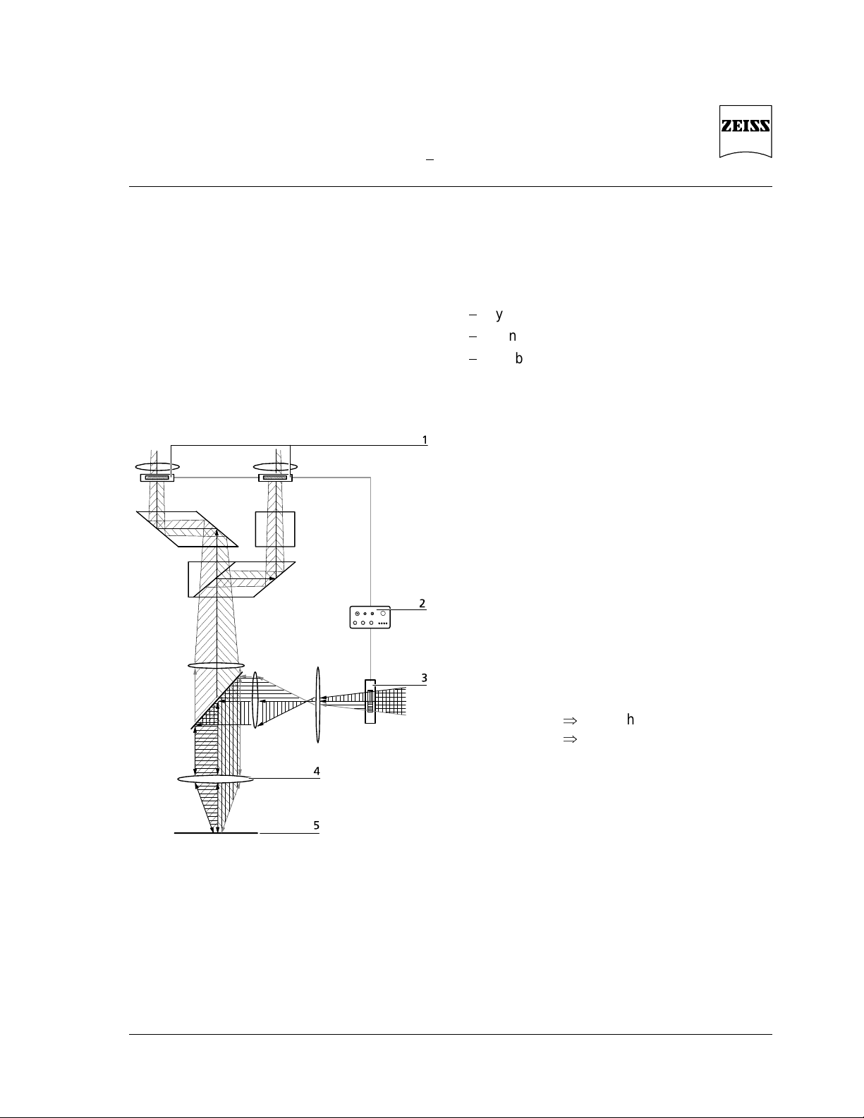
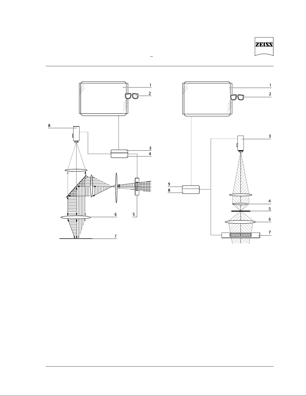
1 Eyepiece with 3D-Shutter
2 3D-CONTROL DSA-3
3 3D illuminator shutter
4 Objective
5 Object plane
Eyepiece version
in a reflected-light microscope
There are three different versions of 3D
microscopy:
eyepiece version
monitor version
combination of eyepiece and monitor
version
2.2.1 Eyepiece version
An LCD shutter (
"3D illumination shutter"
) is
positioned close to the aperture diaphragm and
is used to open or close one half of the beam
path.
With the eyepiece version, the LCD shutter is
controlled via the "
3D-CONTROL DSA-3"
unit.
The centroid of the illumination beam path is
switched in such a way that the object is
illuminated alternately from a right and a left
stereo angle.
The eyepiece shutters are controlled at the
same pulse rate, i.e. each eye
only sees the
image on its own side
.
right eye
right image
left eye
left image
A flicker-free display of the stereo image
composed of the right and left images is made
possible by an appropriately high pulse rate.
When the illuminator - eye allocation is
changed, a pseudostereo effect is created
(height-changed image).
Resolution, contrast and depth can be
optimized with relation to the object via the
aperture diaphragm.
Function Monitor version 3D Microscopy
8 B 40-022-4 e 07/98
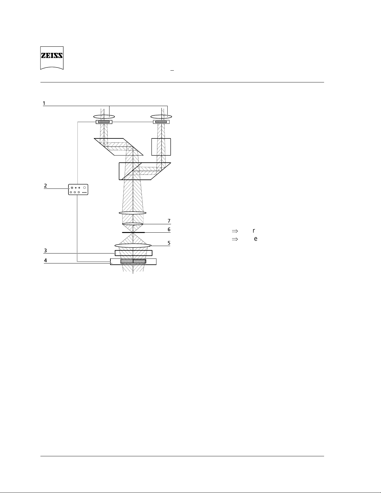
1 Eyepiece with 3D-Shutter
2 3D-CONTROL DSA-3
3 Depolarizer
4 3D illumination shutter
5 Condenser
6 Object plane
7 Objective
Eyepiece version
in a transmitted-light microscope
The depolarizer is required for minimization of
disturbances by the polarization equipment and
facilitates work with birefringent objects
2.2.2 Monitor version
An LCD shutter (
"3D illumination shutter"
) is
positioned close to the aperture diaphragm and
is used to open or close half a side of the beam
path.
With the monitor version, the LCD shutter is
controlled via the "
3MCU II"
unit.
The centroid of the illumination beam path is
switched in such a way that the object is
illuminated alternately from a right and a left
stereo angle.
The camera and the monitor shutters are
controlled at the same pulse rate, i.e. each eye
only sees the image on its own side
.
right eye
right image
left eye
left image
In the monitor version, allocation is made via
the display of the half images in two
perpendicular polarization directions which can
be allocated to the eyes by polarizing glasses.
A flicker-free display of the stereo image
composed of the right and left images is made
possible by an appropriately high pulse rate.
When the illuminator - eye allocation is
changed, a pseudostereo effect is created
(height-changed images).
Resolution, contrast and depth can be
optimized with relation to the object via the
aperture diaphragm.
3D Microscopy Function Monitor version
B 40-022-4 e 07/98 9
1 Monitor shutter
2 Glasses
3 Control unit for monitor shutter
4 MCU II image memory
5 3D illumination shutter
6 Objective
7 Object plane
8 Camera
Monitor version
in a reflected-light microscope
1 Monitor shutter
2 Polarizing glasses
3 Camera
4 Objective
5 Object plane
6 Condenser
7 3D illumination shutter
8 MCU II image memory
9 Control unit for monitor shutter
Monitor version
in a transmitted-light microscope
Function Combined version 3D Microscopy
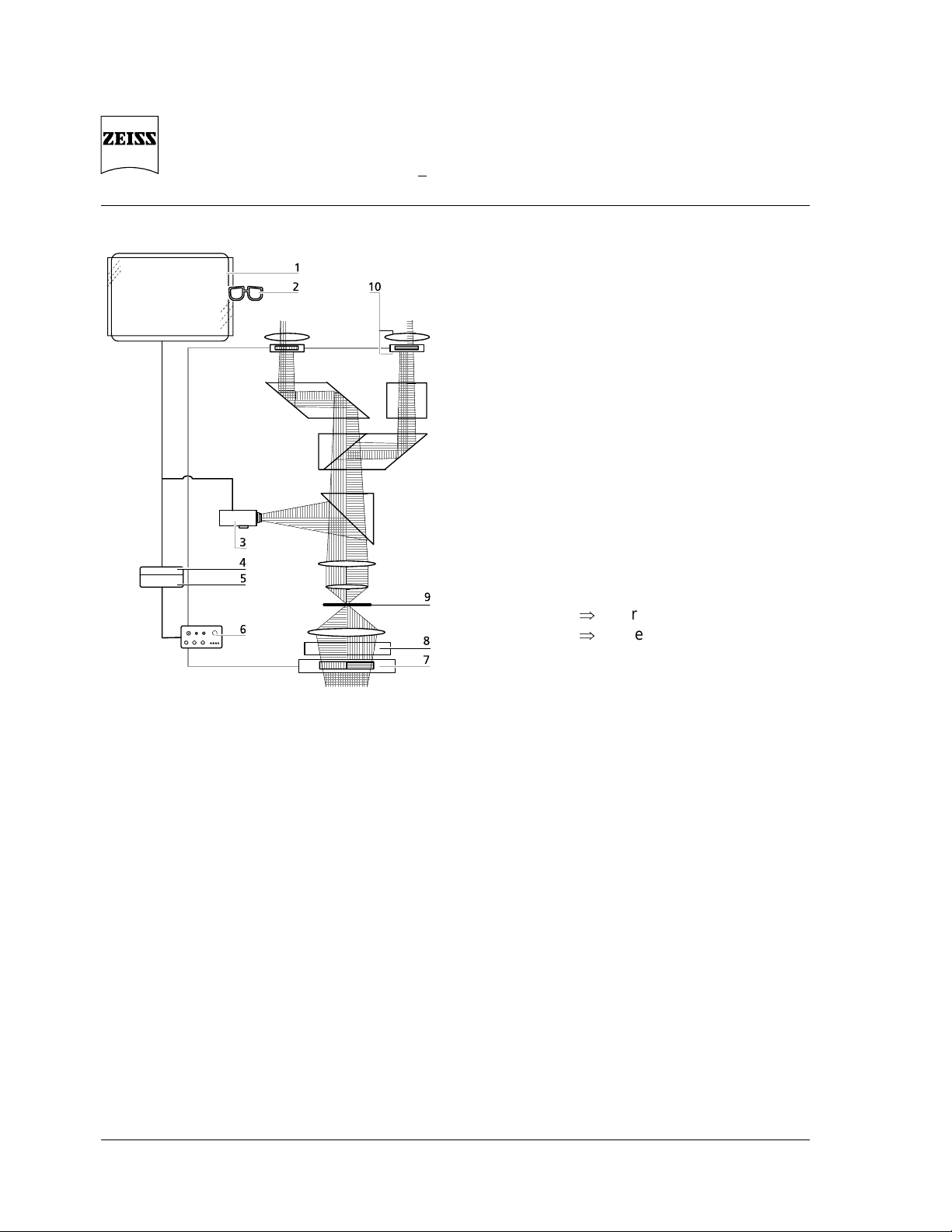
10 B 40-022-4 e 07/98
1 Monitor shutter
2 Polarizing glasses
3 Camera
4 Control unit for monitor shutter
5 MCU II image memory
6 3D-CONTROL DSA-3
7 3D illumination shutter
8 Depolarizer
9 Object plane
10 Eyepiece with 3D Shutter
Combined version
in a transmitted-light microscope
2.2.3 Combination
of eyepiece and monitor version
An LCD shutter (
"3D illumination shutter"
) is
positioned close to the aperture diaphragm and
is used to open or close one half of the beam
path.
With the combined version, the LCD shutter is
controlled via the "
3D-CONTROL DSA-3"
unit.
The centroid of the illumination beam path is
switched in such a way that the object is
illuminated alternately from a right and a left
stereo angle.
The eyepiece shutter and the camera and
monitor shutters are controlled at the same
pulse rate, i.e. each eye
only sees the image
on its own side
.
right eye
right image
left eye
left image
In the monitor version, allocation is made via
the display of the half images in two
perpendicular polarization directions which can
be allocated to the eyes by polarizing glasses.
A flicker-free display of the stereo image
composed of the right and left images is made
possible by an appropriately high pulse rate.
When the illuminator - eye allocation is
changed, a pseudostereo effect is created
(height-changed image).
Resolution, contrast and depth can be
optimized with relation to the object via the
aperture diaphragm.

3D Microscopy Maintenance and care
B 40-022-4 e 07/98 11
2.3 Maintenance and care
2.3.1 General
Never expose the components for 3D
microscopy to inadmissible climatic conditions
(high humidity and temperature) for longer
periods of time.
The components must be protected from dust
and humidity and covered with the dust cover
after every use.
2.3.2 Cleaning of optical
components
The 3D shutter in the eyepieces and in the 3D
illumination shutter are equipped with a
polarizing foil.
The polarizing foils must not be cleaned with
solvents.
The foils are sensitive to scratching.
1 Fuse compartment
2 Voltage selector
3 Holding unit
4 Window
Changing the voltage selector on the rear of the
3D-CONTROL DSA-3 unit
Clean the polarizing foils as follows:
Remove dust using a rubber blower
Use a soft optics cleaning cloth
Use a natural hair brush degreased in alcohol
and dried before.
The glass plate of the window of the CCD
camera can be cleaned using the cleaning buds
supplied.
2.3.3 Change of voltage and fuses
Prior to connection to the line, check whether
the voltage set on the selector at the rear of the
3D-CONTROL DAS-3 unit complies with the line
voltage; it may be necessary to change from
230 V to 115 V.
Pull the power plug before changing the
voltage or the fuses
Use a small screwdriver to turn back the
clamping piece of the fuse holder at the rear
of the 3D-CONTROL DAS-3 unit;
lift the fuse holder out of the fuse
department
Remove the fuses
Pull voltage selector out of its holder
Turn voltage selector around 180° and insert
it back in its holder:
the new voltage is visible in the window
Insert the fuses listed under "
Technical Data"
Insert fuse holder back in the fuse
department until click-stop.

Troubleshooting 3D Microscopy
12 B 40-022-4 e 07/98
2.4 Troubleshooting
The monitor displays colored fringing or
several out-of-focus images:
Switch off MCU II;
switch it on again after 10 seconds
No 3D image is obtained:
monitor shutter does not function;
check switch for monitor shutter on the
control unit; the green lamp lights up only if
the switches are set correctly
parameters on the MCU II are not set
correctly;
check the parameters, mainly Time,
MEMORY IN, MEMORY OUT
camera not positioned correctly;
check whether the camera controls are
aligned perpendicular to the stand and
whether the monitor image follows the
stage motion;
if not, turn the camera
3D illumination shutter is out of alignment;
recenter aperture diaphragm,
recenter 3D illumination shutter
Knob of 3D-CONTROL DAS-3 control units
not set correctly;
check 3D setting of 3D-CONTROL DAS-3
The image flickers:
pulse rate is not set correctly;
set 3D VIS on the 3D CONTROL DAS-3 for
observation, and 3D VIDEO for monitor
observation
A pseudostereoscopic image is displayed,
i.e. heights and depths in the image are
exchanged:
The toggle switch of the 3D CONTROL DAS3 is not set correctly;
set toggle switch to "STEREO"
For observation, exchange eyepieces for 3D
shutter
For monitor observation,
set toggle switch of 3D CONTROL DAS-3 to
"STEREO";
if required, change "Scope LCD" parameters
in the CONFIG menu of the MCU II
For monitor observation,
set the switch of the control unit for the
monitor shutter to "stereo mode"
Note:
If inverted microscopes are used in transmitted
light - e.g. the Axiovert 100/135/135 M remember that observation is made from the
opposite side of the instrument if manipulators,
needles and electrodes are used.
3D Microscopy Technical Data
B 40-022-4 e 07/98 13
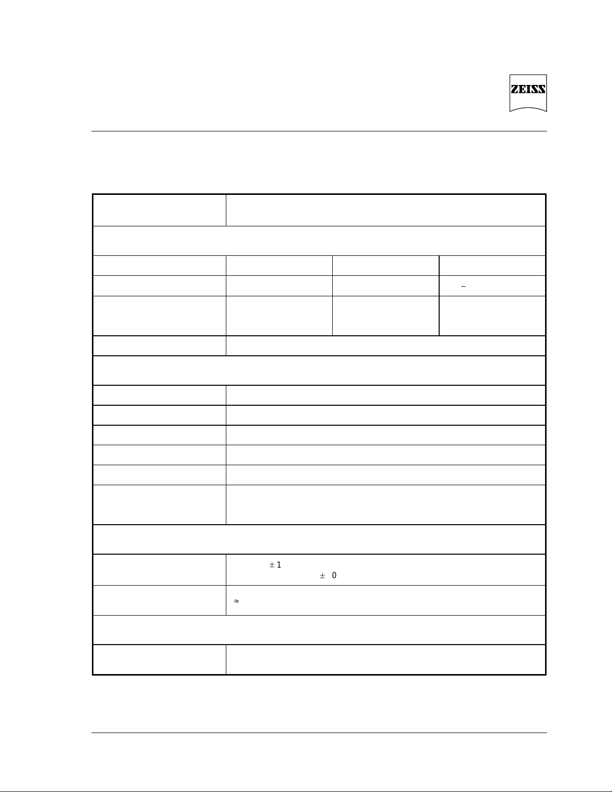
3 Technical Data
Parameters Description
Ambient conditions
Operation Storage Transport
Temperature + 10°C ... + 35°C 0°C ... + 35°C
20°C ... + 50°C
Humidity max. 75% at 35°C
< 90% at 30°C
condensation water not
admissible
< 90% to 30°C
condensation water not
admissible
Conditions of use Dust-free environment, absorption-free worktable
Safety
Protection degree I
Protection type IP 20
Excess voltage category II
Pollution degree 2
Radio interference suppression in accordance with EN 55011 (Class B)
Insensitivity to noise in accordance with EN 50082-1
The components for 3D microscopy meet the requirements of the EC directive
89/336/EEC and the EMC legislation of November 9, 1992
Power supply
3D-CONTROL DSA-3
230 VAC 10%, 50/60 Hz
switchable to 115 VAC 10%, 50/60 Hz
Power consumption of the overall
system
30 VA; minimal 7 VA; maximal 200 VA (depending on configuration)
Fuses
Line input
3D-CONTROL DSA-3
115 VAC: T 0,2 A/250 V in accordance with IEC 127
230 VAC: T 0,1 A/250 V in accordance with IEC 127
For MCU II, monitor shutter, monitor and microscope, see the enclosed Technical Data sheets.

3D Microscopy
Contents Axiovert 100/135
14 B 40-022-4 e 09/98

3D Microscopy
Axiovert 100/135/135 M Contents
B 40-022-4 e 09/98 15
3D Microscopy for
Axiovert 100/135/135 M
Contents
1 Components for 3D Microscopy
Overview.................................................. 16
2 Eyepiece version................................................................................................ 18
2.1 Converting the microscope .............................................................................................. 18
2.2 3D-CONTROL DSA-3 Control Unit.................................................................................... 20
2.2.1 Connections..................................................................................................................... 20
2.2.2 Controls........................................................................................................................... 20
2.3 Adjustment...................................................................................................................... 21
2.3.1 Adjustment of 3D illumination shutter.............................................................................. 21
2.3.2 Check the contrast....................................................................................................... .... 22
2.3.3 Check whether image is upright ...................................................................................... 23
3 Monitor version................................................................................................. 24
3.1 Conversion....................................................................................................................... 25
3.2 MCU II Control Unit.........................................................................................................27
3.2.1 Controls........................................................................................................................... 27
3.2.2 Basic settings for 3D microscopy ...................................................................................... 27
3.3 Adjustment...................................................................................................................... 28
3.4 3D video recordings.........................................................................................................29
3.5 Printing of 3D video recordings........................................................................................ 29
4 Eyepiece and monitor version......................................................................... 30
4.1 Conversion and adjustment ............................................................................................. 30
4.2 Observation ..................................................................................................................... 31
4.2.1 Eyepiece observation........................................................................................................ 31
4.2.2 Monitor observation ........................................................................................................ 31
Illustrations
Fig. 1 Overview ......................................................................................................................... 16
Fig. 2 Connections for eyepiece version..................................................................................... 18
Fig. 3 Changing the voltage selector on rear of 3D-CONTROL DSA-3 ........................................ 18
Fig. 4 Insertion of 3D illumination shutter.................................................................................. 19
Fig. 5 Insertion of depolarizer.................................................................................................... 19
Fig. 6 3D-CONTROL DSA-3 control unit, front ........................................................................... 20
Fig. 7 Adjustment of 3D illumination shutter, pupil.................................................................... 21
Fig. 8 Labels to mark the eyepieces and plugs............................................................................ 23
Fig. 9 Wiring diagram for monitor version ................................................................................. 24
Fig. 10 Attachment of monitor shutter........................................................................................ 25
Fig. 11 Rear of MCU II................................................................................................................. 25
Fig. 12 Attachment of camera.....................................................................................................26
Fig. 13 MCU II controls, front ...................................................................................................... 27
Fig. 14 Wiring diagram for video prints........................................................................................ 29
Fig. 15 Wiring diagram for eyepiece and monitor versions........................................................... 30

3D Microscopy
Overview Axiovert 100/135/135 M
16 B 40-022-4 e 09/98
1 Components for 3D Microscopy Overview
Fig. 1 Overview

3D Microscopy
Axiovert 100/135/135 M Overview
B 40-022-4 e 09/98 17
Axiovert 100/135/135 M
Eyepiece version Monitor version Eyepiece and monitor version
4 3D illumination shutter 3D illumination shutter 3D illumination shutter
2 Eyepiece PL 10x/25 with 3D shutter Eyepiece PL 10x/25 with 3D shutter
5 3D-CONTROL DSA-3 3D-CONTROL DSA-3
3 LD condenser 0.55
Ph1 Ph2, PH3, DIC, DIC
Cat. No. 451359
LD condenser 0.55
Ph1 Ph2, PH3, DIC, DIC
Cat. No. 451359
LD condenser 0.55
Ph1 Ph2, PH3, DIC, DIC
Cat. No. 451359
1 3D depolarizer
Axiovert 100/135/135 M
3D depolarizer
Axiovert 100/135/135 M
Centering telescope (Axiovert 100)
Cat. No. 444830
Centering telescope (Axiovert 100)
Cat. No. 444830
Centering telescope (Axiovert 100)
Cat. No. 444830
6 TV-Adapter 60 C 2/3“ TV-Adapter 60 C 2/3“
7,8,9
10
11
12
3D video equipment with monitor
shutter including camera, monitor
and polarizing glasses
3D video equipment with monitor
shutter including camera, monitor
and polarizing glasses
BNC cable
Key to Fig. 1
1 3D depolarizer Axiovert 100/135/135 M
2 Eyepieces with 3D shutter
3 LD condenser
4 3D illumination shutter
5 3D-CONTROL DSA-3
6 TV adapter
7 Camera
8 MCU II control unit
9 Control unit for monitor shutter
10 17“ monitor
11 Monitor shutter
12 Polarizing glasses

3D Microscopy
Eyepiece version Axiovert 100/135/135 M
18 B 40-022-4 e 09/98
2 Eyepiece version
2.1 Converting the microscope
1 Eyepieces with 3D shutter
2 3D-CONTROL DSA-3
3 Line connection
4 3D illumination shutter
Fig. 2 Connections for eyepiece version
1 Fuse compartment
2 Voltage selector
3 Holding unit
4 Window
Fig. 3 Changing the voltage selector on rear of
3D-CONTROL DSA-3
Set up the microscope in accordance with
the operating instructions of the Axiovert
100/135/135 M
Equip the microscope with LD condenser
0.55 Ph1, Ph2, Ph3, DIC, DIC
Connect the components for 3D microscopy
to the 3D-CONTROL DSA-3 control unit:
Fig.
2
Connect eyepieces with 3D shutter to the
EYEPIECE sockets
Connect 3D illumination shutter to the
ILLUMINATION SHUTTER socket
Connection to the line
:
Prior to connection to the line,
check wether the voltage set on the
selector at the rear of the 3DCONTROL DSA-3 unit complies with
the line voltage; it may be necessary to
change from 230 V to 115 V or vice
versa:
Fig.
3
Pull the power plug before changing the
fuses or the voltage
Use a small screwdriver to press out the
clamping piece of the fuse holder at the rear
of the 3D-CONTROL DSA-3 unit; lift the fuse
holder out of the fuse compartment
Remove the fuses
Pull voltage selector out of its holder
Turn voltage selector around 180° and insert
it back in its holder:
the new voltage is visible in the window
Insert the fuses listed under
Technical Data
Insert fuse holder back in the fuse
compartment until click-stop

3D Microscopy
Axiovert 100/135/135 M Eyepiece version
B 40-022-4 e 09/98 19
1 Stop screw (hexagonal, SW 2, varnish-coated)
2 LD condenser
3 Fixation screw (hexagonal, SW 2)
4 Recess
5 3D illumination shutter
Fig. 4 Insertion of 3D illumination shutter
1 Depolarizer
2 Recess (analyzer opening)
Fig. 5 Insertion of depolarizer
Insert eyepieces with 3D shutter in the
binocular tube
Insert 3D illumination shutter in the recess
provided in the condenser of the
Axiovert 100/135/135 M, close to the
aperture diaphragm
Fig. 4
Do not touch the polarizing foil, since it can
be easily scratched.
For 3D microscopy, remove the DIC prism
from the condenser turret, if used.
Insert depolarizer in the recess (analyzer
opening) below the objective nosepiece:
Fig. 5

3D Microscopy
Eyepiece version Axiovert 100/135/135 M
20 B 40-022-4 e 09/98
2.2 3D-CONTROL DSA-3
Control Unit
Fig. 6 3D-CONTROL DSA-3 control unit, front
2.2.1 Connections
Fig. 6
EYEPIECE
Connection sockets for eyepieces with 3D
shutter
ILLUMINATION SHUTTER
Connection socket for 3D illumination shutter
TRIGGER
Trigger input socket for connection
of the MCU II
2.2.2 Controls
Fig. 6
STEP
If the rotary switch is in the "
STEP"
position,
this button can be used to change to statically
inclined illumination for the left and right beam
path.
STEREO/PSEUDO
Toggle switch which determines the phase
position between the shutters.
In the "STEREO" position, a stereoscopic
(upright) image is created, while the image in
the "PSEUDO" position is pseudostereoscopic
(vertically reversed).
Rotary switch for the setting of different
modes:
STEP
step mode
(inclined illumination from the
left or right)
2D
brightness, if toggle switch is
in "STEREO" position
3D VIS
3D image, eyepiece version
3D VIDEO
3D image, monitor version
E1, E2
Potentiometer for voltage adjustment of the
eyepiece shutter (factory-aligned);
E1 acts on the left EYEPIECE socket;
E2 acts on the right EYEPIECE socket
I1, I2
Potentiometer for voltage adjustment of the 3D
illumination shutter
(factory-aligned)
I1 acts on one side of the
3D illumination shutter,
I2 acts on the other side of the
3D illumination shutter

3D Microscopy
Axiovert 100/135/135 M Eyepiece version
B 40-022-4 e 09/98 21
2.3 Adjustment
Fig. 7 Adjustment of 3D illumination shutter,
pupil
Use cover slip as an object and focus on it
using the 10x objective;
after adjustment, check the setting using the
objective of the highest magnification
2.3.1 Adjustment of 3D illumination
shutter
Move rotary switch of the 3D-CONTROL
DSA-3 to the STEP position:
Fig. 6
Observe the pupil:
Axiovert 100: remove the eyepiece and
insert the centering telescope,
Axiovert 135/135 M with Bertrand lens in
the 4x turret:
use centering telescope or Bertrand lens to
focus on the aperture diaphragm;
one pupil half will be bright, the other dark:
Fig. 7
Move 3D illumination shutter to the side
until both pupil halves appear identical in
size;
if required, reset the stop screw;
Use fixation screw to hold 3D illumination
shutter in position
Close aperture diaphragm;
check center position

3D Microscopy
Eyepiece version Axiovert 100/135/135 M
22 B 40-022-4 e 09/98
2.3.2 Check the contrast
If colors or inhomogeneity are visible in the
pupil, change the voltage settings for the 3D
illumination shutter and the 3D shutter of the
eyepieces on the potentiometers of the 3DCONTROL DAS-3 until optimum contrast and
brightness are achieved.
There are two ways of adjusting the voltage of
the 3D illumination shutter:
3D illumination shutter in the
3D illumination unit,
Eyepieces with 3D shutter not in the
microscope
Use centering telescope (100) or Bertrand
lens (135/135 M) to view the half pupils
Set the rotary switch of the 3D-CONTROL
DSA-3 to 2D:
brightness position
View the contrast;
if required, use screwdriver to reset I1 or I2
until both halves of the pupil display equal
brightness
3D illumination shutter outside the microscope
In the brightness position, view the 3D
illumination shutter against a white
background and reset I1 or I2 until both
halves display equal brightness.
There are two ways of adjusting the voltage of
the 3D shutters in the eyepieces:
3D illumination shutter outside the microscope,
eyepieces with 3D shutter in the microscope
Set the rotary switch of the 3D-CONTROL
DSA-3 to 2D:
brightness position
View the contrast;
if required, use screwdriver to reset E1 or E2
until both eyepieces display equal brightness
Recommended:
Eyepieces with 3D shutter outside the
microscope
Hold eyepieces directly in front of your eye
or
reverse eyepieces and view them from
the rear from some distance
View both eyepieces against a white
background in the brightness position and
reset E1 and E2 until both eyepieces feature
an identical colorless gray shade and
identical brightness.
After conclusion of the voltage settings, the
eyepieces with 3D shutter are inserted again. It
may happen that brightness differences occur
again between right and left; in such a case
slightly turn the eyepieces in the tube
( 10°);
set maximum and homogeneous brightness

3D Microscopy
Axiovert 100/135/135 M Eyepiece version
B 40-022-4 e 09/98 23
2.3.3 Check whether image is upright
Fig. 8 Labels to mark the eyepieces
and plugs
Set the rotary switch of the 3D-CONTROL
DAS-3 to
3D VIS
Set the toggle switch of the 3D-CONTROL
DAS-3 to
STEREO
View a familiar object;
if the image is not upright, exchange the
eyepieces
Mark the eyepieces and the appropriate
plugs with the supplied labels
Fig. 8
E1 and E2 for the left and right
connection plug
L and R for the left and right
eyepiece
To avoid the cables on the eyepieces with 3D
shutter to be damaged, attach them to the rear
without any slack and fix them to the stand
using the supplied cable clamps.
Place the required object on the stage, focus
on it, set Köhler illumination and adjust
aperture diaphragm until optimum contrast
is achieved

3D Microscopy
Eyepiece version Axiovert 100/135/135 M
24 B 40-022-4 e 09/98
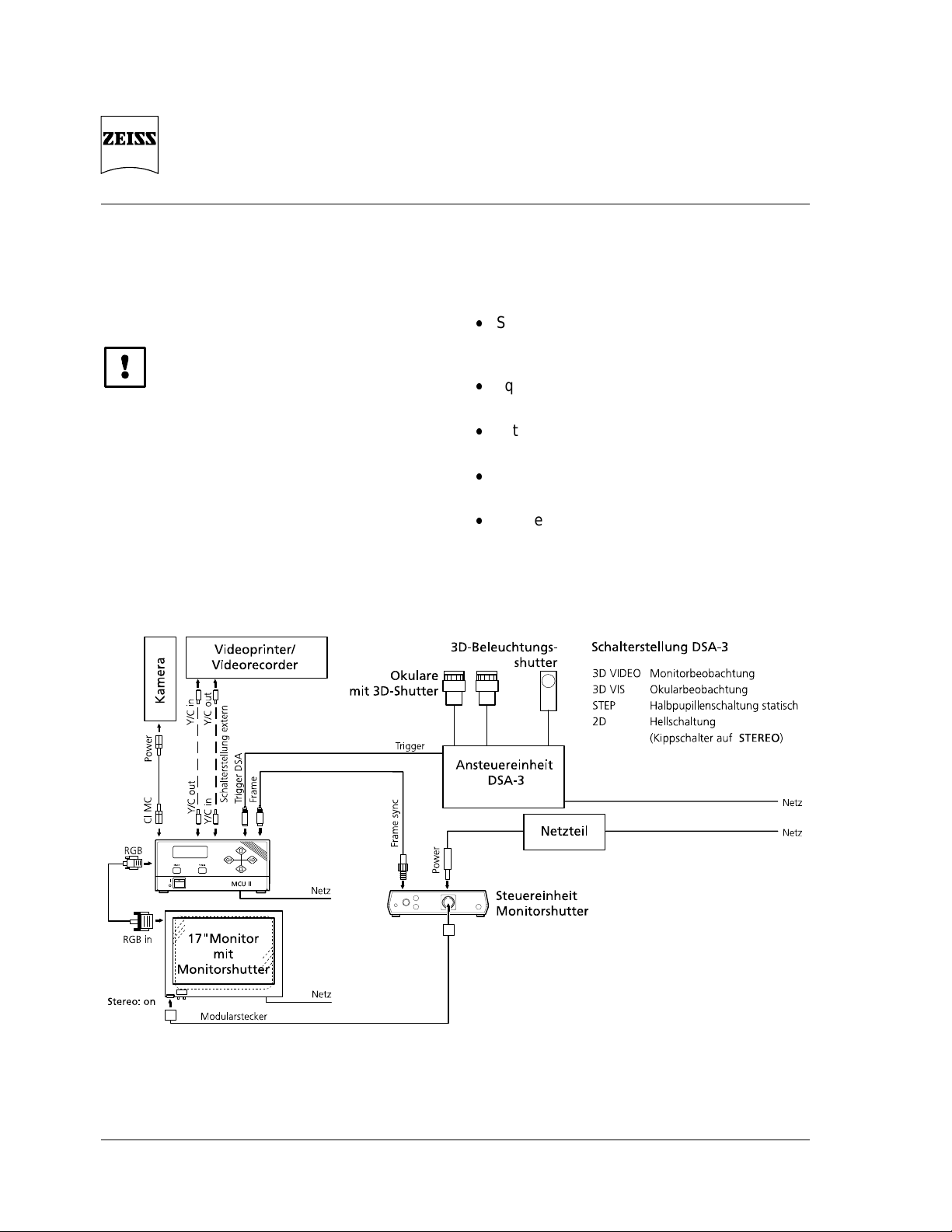
3 Monitor version
The following components from KAPPA are
required for the monitor version:
MCU II control unit
CF 15/4 MC-S camera
CF 15/4 connecting cable to MCU II
Line cable
Monitor (100 Hz) with connecting cable and
attached monitor shutter
Control unit for monitor shutter, with power
unit and connecting cable
3D illumination shutter
Control and supply cable between MCU II
and 3D illumination shutter/monitor shutter
Polarizing glasses
Fig. 9 Wiring diagram for monitor version

3D Microscopy
Axiovert 100/135/135 M Monitor version
B 40-022-4 e 09/98 25
3.1 Conversion
1 Monitor
2 Bracket
3 Monitor shutter
Fig. 10 Attachment of monitor shutter
1 Loop-through input for video printer/video recorder
2 Socket for camera cable
3 Socket for video printer/video recorder
4 Output for monitor with Y/C input
5 Output for monitor with (F)BAS video input
6 Socket for 3D-CONTROL DAS-3 trigger
7 Socket for 3D illumination shutter
Fig. 11 Rear of MCU II
Set up the microscope in accordance with
the operating instructions for the
Axiovert 100/135/135 M
Equip the microscope with LD condenser
0.55 Ph1, Ph2, Ph3, DIC, DIC
Use Velcro tape to stick the bracket to the
monitor housing
Insert monitor shutter in the bracket in such
a way that the connector sockets are
positioned on the bottom right
Before connecting the components for the
monitor version, make absolutely sure to note
the following:
First read the enclosed manual from Kappa
entitled "
Color TV Camera for Microscopy
and 3D Images
";
chapter 5, "
Safety regulations
", should be
observed in particular.
Cable connections may only be made if the
various components are switched off.
It is important to use only the connectors
listed in the operating instructions of the
camera system
Make sure that the cables are not bent or
laid out in too narrow a radius.
Set up the video equipment with monitor
shutter and make the electrical connections.
Fig. 9/Fig. 11
8 External triggering of the
Freeze
function
9 Cold instrument socket /fuse holder
10
INTERN
: standard setting
EXTERN
: if video printer/video recorder are
connected
11 Output for monitor with RGB input
12 Connector for monitor shutter

3D Microscopy
Monitor version Axiovert 100/135/135 M
26 B 40-022-4 e 09/98
1 Camera
2 Adapter
3 Phototube
Fig. 12 Attachment of camera
Connect camera to phototube via
instrument-specific video adapter or video
zoom;
the following adapters are recommended:
Video zoom adapter 0.4x 2x
with C-mount
TV adapter 1x for chip camera
with C-mount
Fig. 12
Push 3D illumination shutter in the recess
provided in the condenser of the
Axiovert 100/135, close to the aperture
diaphragm:
Fig. 4
Do not touch the polarizing foil, since it can
be easily scratched.
Switch components on in the following
order:
microscope
monitor
MCU II control unit
Running-up time of the monitor shutter:
3 min

3D Microscopy
Axiovert 100/135/135 M Monitor version
B 40-022-4 e 09/98 27
3.2 MCU II Control Unit
1 Line switch
2 Menu change
3 Menu display (LCD)
4 Storage key for current image
5 Arrow keys for parameter control in the menu
Fig. 13 MCU II controls, front
3.2.1 Controls
Fig. 13
LCD-Display
Display of menu options
Control keys
Arrow keys for options and settings within the
menus
Mode
Key for menu change
Freeze
Key for storage of the current image;
the stored image is constantly made available
at the video ports
3.2.2 Basic settings for 3D microscopy
USER MENU User 1
RESET MENU Scope LC AB <BA>
(corresponds to stereo/
pseudostereo change)
White set Set Lock
R-B 50 %
Integration Mode: Auto
Time: 20 ms
Clock: Normal
Camera menu Enhance High
AGC On
AIT Off
Exposure Measure Integral
Level 50 %
MCU control Gain: 80 %
Offset: 50 %
Color: 50 %
Hue: 50 %
Red: 50 %
Blue: 50 %
Memory In Frame
Memory Out 100 Hz
Frame
Stereo/Pseudostereo
Reset ...

3D Microscopy
Monitor version Axiovert 100/135/135 M
28 B 40-022-4 e 09/98
3.3 Adjustment
Use cover slip as an object and focus on it
using the10x objective;
after adjustment, check the setting using the
objective of the highest magnification
Check center position of the 3D illumination
shutter in the same way as with the eyepiece
version;
remove camera cable from the MCU II or
from the camera:
see page 21
Place the required object on the stage and
focus on it
Switch beam path to camera/TV
A 2-dimensional image first appears on the
monitor;
if the image is reversed, turn the camera
around 180°
Wear polarizing glasses
The image appears in 3 dimensions on the
monitor
Place required object on the stage,
focus on it, set Köhler illumination and
adjust aperture diaphragm until optimum 3D
contrast is achieved

3D Microscopy
Axiovert 100/135/135 M Monitor version
B 40-022-4 e 09/98 29
3.4 3D video recordings
3D sequences can generally be recorded and
played back using a video recorder.
This requires an S-VHS recorder and an
S-VHS video tape.
Fig. 14 Wiring diagram for video prints
Connecting the video recorder:
Set the toggle switch of the MCU II to
Extern
Fig. 14
Connect Y/C-In of the MCU II with Y/C-Out
of the video recorder
Connect Y/C-Out of the MCU II with Y/C-In
of the video recorder
Recording, playback:
Activate
TBC
(Time Base Corrector) on the
video recorder
First activate the
Pause/Still
key, then the
Record
key of the video recorder
Use the
Pause
key to interrupt recording
Interrupt playback using the
Pause
key and
end it using the
Stop
key.
3.5 Printing of 3D video
recordings
Stored 3D video recordings can be printed as
video prints:
Fig. 14
Storing the image:
Set
100 Hz
in the
MEMORY OUT
menu of
the MCU II
Set
Frame
in the
MEMORY IN
menu of the
MCU II
Store the current image via the
Freeze
key
Printing:
Set
50 Hz
in the
MEMORY OUT
menu of
the MCU II
Set
Frame
via the key;
then use the key to go to
Field
and print
the two half images - field 1 and field 2 one after the other
3D Microscopy
Eyepiece and monitor version Axiovert 100/135/135 M
30 B 40-022-4 e 09/98
4 Eyepiece and
monitor version
Before connecting the components, first read
the enclosed manual from Kappa entitled
"
Color TV Camera for Microscopy and 3D
Images
";
chapter 5, "
Safety regulations
", should be
observed in particular.
4.1 Conversion and adjustment
Set up the microscope in accordance with
the operating instructions of the
Axiovert 100/135/135 M
Equip the microscope with LD condenser
0.55 Ph1, Ph2, Ph3, DIC, DIC
Set up the eyepiece version:
see page 18
Set up the monitor version:
see page 24
Connect eyepiece and monitor version in
accordance with the wiring diagram
Fig. 15
Fig. 15 Wiring diagram for eyepiece and monitor version

3D Microscopy
Axiovert 100/135/135 M Eypiece and monitor version
B 40-022-4 e 09/98 31
4.2 Observation
This is a combination of the eyepiece and the
monitor version. The image is 3-dimensional
when you look through the eyepiece or on the
monitor.
4.2.1 Eyepiece observation
Set the beam path to observation on the
stand
Set the
3D VIS
mode via the rotary switch
of the 3D-CONTROL DAS-3 control unit
Place the required object on the stage,
focus on it, set Köhler illumination and
adjust the
aperture diaphragm until optimum 3D
contrast is achieved;
the image appears 3-dimensional through
the eyepiece
4.2.2 Monitor observation
Switch beam path to Camera/TV on the
stand
Set the
3D VIDEO
mode via the rotary
switch of the 3D-CONTROL DAS-3 control
unit
Place the required object on the stage and
focus on it;
the image on the monitor is 2-dimensional
first
If the image is reversed, turn the camera
around 180°
Wear polarizing glasses;
the image on the monitor is 3-dimensional
Use a familiar object to check whether the
image is upright;
if the image is not upright, switch to
Scope
LCD
in the
RESET MENU
of the MCU II
control unit
Focus depending on the object;
adjust aperture diaphragm until optimum
3D contrast is achieved

3D Microscopy
Eyepiece and monitor version Axiovert 100/135/135 M
32 B 40-022-4 e 09/98
 Loading...