


Zeiss Humphrey HFAII-i User manual
Humphrey ®
Field Analyzer
Series HFA II - i
Field Service Guide
CONFIDENTIAL & PROPRIETARY
Part No. 52235, Revision C
November 2005
PROPRIETARY NOTICE
Information contained in this document is copyright Carl Zeiss Meditec Incorporated and may not be reproduced in full or in part by any person without prior written approval of Carl Zeiss Meditec. Its purpose is to provide the User with adequately detailed information so as to repair, maintain, and order spare parts for the instrument supplied. Every effort has been made to keep the information contained in this document current and accurate as of the date of publication or revision. However, no guarantee is given or implied that the document is error-free or that it is accurate with regard to any specification.
TRADEMARK CREDITS
Humphrey Field Analyzer is a registered trademark of Carl Zeiss Meditec Inc.
All trademarks, registered trademarks, and trade names that appear in this manual are the property of their respective holders.
Revision C © 2005 by Carl Zeiss Meditec Inc. All rights reserved.
Carl Zeiss Meditec Inc.
5160 Hacienda Drive
Dublin, CA 94568
ii

REVISION CONTROL LIST
Document: Field Analyzer Series HFA II - i Field Service Guide Part No.: 52235 - Revision C
Issued Date: November 2005
Listed at the bottom of each page is the part number of the field service guide, along with the Revision letter and date for that page (for example, 52235C1105). Subsequent revisions to a page will be noted by a corresponding change to the Revision letter and date.
Pages in this document are at Revision C unless noted otherwise below.
Note - The Revision “B” Humphrey Field Analyzer Series HFA II-i Field Service Guide, P/N 52235 has been revised to Revision “C”. The new revision updates all references from “Humphrey Systems” to “Carl Zeiss Meditec Inc. (CZMI)”.
Page Revision |
Page Revision |
Page Revision |
Page Revision |
iii

Humphrey Field Analyzer II - i |
Table of Contents |
Table of Contents
Section 1 - General Information
1.1 |
About This Field Service Guide . . . . . . . . . . . . . . . . . . . . . . . . . . . . . . . . |
1 - 3 |
|
|
1.1.1 |
General Information . . . . . . . . . . . . . . . . . . . . . . . . . . . . . . . . . . . |
1 - 3 |
|
1.1.2 |
Conventions . . . . . . . . . . . . . . . . . . . . . . . . . . . . . . . . . . . . . . . . . |
1 - 4 |
1.2 |
About Service Bulletins . . . . . . . . . . . . . . . . . . . . . . . . . . . . . . . . . . . . . . |
1 - 4 |
|
1.3 |
HFA II - i Service Strategy . . . . . . . . . . . . . . . . . . . . . . . . . . . . . . . . . . . . |
1 - 5 |
|
|
1.3.1 |
Two-Level Service Strategy . . . . . . . . . . . . . . . . . . . . . . . . . . . . . . |
1 - 5 |
|
1.3.2 Three Steps to Completing an HFA II - i Service Call . . . . . . . . . . |
1 - 5 |
|
|
1.3.3 HFA II - i Field Service Paperwork Requirements . . . . . . . . . . . . . |
1 - 6 |
|
1.4 |
Configuration Parameters . . . . . . . . . . . . . . . . . . . . . . . . . . . . . . . . . . . . |
1 - 8 |
|
1.5 |
Precautions . . . . . . . . . . . . . . . . . . . . . . . . . . . . . . . . . . . . . . . . . . . . . . . |
1 - 8 |
|
1.6 |
Internal Layout . . . . . . . . . . . . . . . . . . . . . . . . . . . . . . . . . . . . . . . . . . . |
1 - 10 |
|
1.7 |
Special Topics . . . . . . . . . . . . . . . . . . . . . . . . . . . . . . . . . . . . . . . . . . . . |
1 - 10 |
|
|
1.7.1 |
The Touch Screen . . . . . . . . . . . . . . . . . . . . . . . . . . . . . . . . . . . |
1 - 10 |
|
1.7.2 |
Gaze Tracking . . . . . . . . . . . . . . . . . . . . . . . . . . . . . . . . . . . . . . . |
1 - 11 |
|
1.7.3 Head Tracking / Auto Pupil / Vertex Monitoring . . . . . . . . . . . . . |
1 - 14 |
|
|
1.7.4 HFA II - i Light Intensity Fundamentals . . . . . . . . . . . . . . . . . . . . |
1 - 15 |
|
|
1.7.5 Comparing HFA II and the HFA II - i . . . . . . . . . . . . . . . . . . . . . |
1 - 15 |
|
1.8 |
Peripherals . . . . . . . . . . . . . . . . . . . . . . . . . . . . . . . . . . . . . . . . . . . . . . |
1 - 20 |
|
1.9 |
Specifications . . . . . . . . . . . . . . . . . . . . . . . . . . . . . . . . . . . . . . . . . . . . . |
1 - 22 |
|
Section 2 PM and System Checkout
2.1 System Checkout Checklist . . . . . . . . . . . . . . . . . . . . . . . . . . . . . . . . . . . 2 - 3 2.2 Preventive Maintenance Procedure . . . . . . . . . . . . . . . . . . . . . . . . . . . . . 2 - 8
Section 3 Parts Removal / Replacement
3.1 General Instructions . . . . . . . . . . . . . . . . . . . . . . . . . . . . . . . . . . . . . . . . . . 3 - 4 3.1.1 Removal from Power Table . . . . . . . . . . . . . . . . . . . . . . . . . . . . . 3 - 10 3.2 Front Cover Assembly Removal . . . . . . . . . . . . . . . . . . . . . . . . . . . . . . . . 3 - 11
3.3 Rear Cover Assembly Removal . . . . . . . . . . . . . . . . . . . . . . . . . . . . . . . . 3 - 12 3.4 Operator Panel Assembly Removal . . . . . . . . . . . . . . . . . . . . . . . . . . . . . 3 - 13 3.5 Drive Housing Assembly Removal . . . . . . . . . . . . . . . . . . . . . . . . . . . . . . 3 - 15
Confidential and Proprietary
52235C1105 |
v |
Field Service Guide |

Table of Contents |
Humphrey Field Analyzer II - i |
3.6 CPU/Backplane Enclosure Removal . . . . . . . . . . . . . . . . . . . . . . . . . . . . 3 - 17 3.7 CPU and Backplane Removal . . . . . . . . . . . . . . . . . . . . . . . . . . . . . . . . . 3 - 18 3.8 Motor Drive PCB Removal . . . . . . . . . . . . . . . . . . . . . . . . . . . . . . . . . . . 3 - 19 3.9 Separation of the CPU PCB from the Backplane Board . . . . . . . . . . . . . . 3 - 20 3.10 Power Supply Removal . . . . . . . . . . . . . . . . . . . . . . . . . . . . . . . . . . . . . . 3 - 21 3.11 CRT PCB Removal . . . . . . . . . . . . . . . . . . . . . . . . . . . . . . . . . . . . . . . . . 3 - 22 3.12 CRT Removal . . . . . . . . . . . . . . . . . . . . . . . . . . . . . . . . . . . . . . . . . . . . . 3 - 23 3.13 Touch Screen Removal . . . . . . . . . . . . . . . . . . . . . . . . . . . . . . . . . . . . . . 3 - 25 3.14 CCD Camera Removal . . . . . . . . . . . . . . . . . . . . . . . . . . . . . . . . . . . . . . 3 - 26 3.15 Fixation Interconnect PCB Removal . . . . . . . . . . . . . . . . . . . . . . . . . . . . 3 - 26 3.16 Central Fixation LED/Beamsplitter Removal . . . . . . . . . . . . . . . . . . . . . . 3 - 27 3.17 Projection Assembly Removal . . . . . . . . . . . . . . . . . . . . . . . . . . . . . . . . . 3 - 28 3.18 Projection Interconnect PCB Removal . . . . . . . . . . . . . . . . . . . . . . . . . . . 3 - 30 3.19 Film Wedge/Motor Removal . . . . . . . . . . . . . . . . . . . . . . . . . . . . . . . . . . 3 - 30 3.20 Glass Wedge/Motor Removal . . . . . . . . . . . . . . . . . . . . . . . . . . . . . . . . . . 3 - 31 3.21 Color Wheel / Aperture Wheel Removal . . . . . . . . . . . . . . . . . . . . . . . . . 3 - 32 3.22 Carriage Motor Removal . . . . . . . . . . . . . . . . . . . . . . . . . . . . . . . . . . . . . 3 - 33 3.23 Shutter Removal . . . . . . . . . . . . . . . . . . . . . . . . . . . . . . . . . . . . . . . . . . . 3 - 34 3.24 Shutter Motor Removal . . . . . . . . . . . . . . . . . . . . . . . . . . . . . . . . . . . . . . 3 - 35 3.25 Carriage Motor Belt Removal . . . . . . . . . . . . . . . . . . . . . . . . . . . . . . . . . . 3 - 35 3.26 Horizontal (X-axis) Turret Motor Removal . . . . . . . . . . . . . . . . . . . . . . . . 3 - 36 3.27 Horizontal (X-axis) Turret Motor Belt Removal . . . . . . . . . . . . . . . . . . . . 3 - 37 3.28 Vertical (Y-axis) Turret Belt/Motor Removal . . . . . . . . . . . . . . . . . . . . . . . 3 - 39 3.29 Brightness Detector (PCB) Replacement . . . . . . . . . . . . . . . . . . . . . . . . . 3 - 40 3.30 Lower Turret Removal . . . . . . . . . . . . . . . . . . . . . . . . . . . . . . . . . . . . . . . 3 - 41 3.31 Turret Cable Assembly Removal . . . . . . . . . . . . . . . . . . . . . . . . . . . . . . . 3 - 42 3.32 Chinrest/Headrest Switch Assembly Removal . . . . . . . . . . . . . . . . . . . . . 3 - 42 3.33 Chinrest Y-axis Belt/Motor Removal . . . . . . . . . . . . . . . . . . . . . . . . . . . . 3 - 43 3.34 Patient Support Horizontal (X-axis) Belt/Motor Removal . . . . . . . . . . . . . 3 - 44 3.35 Chinrest Vertical Slide and Lead Screw Removal . . . . . . . . . . . . . . . . . . . 3 - 47 3.36 Chinrest Horizontal Slide Removal . . . . . . . . . . . . . . . . . . . . . . . . . . . . . 3 - 48 3.37 Trial Lens Holder Assembly Removal . . . . . . . . . . . . . . . . . . . . . . . . . . . 3 - 49 3.38 Top Fan Removal . . . . . . . . . . . . . . . . . . . . . . . . . . . . . . . . . . . . . . . . . . 3 - 50 3.39 Bowl IR LED Assembly Removal . . . . . . . . . . . . . . . . . . . . . . . . . . . . . . . 3 - 51
Confidential and Proprietary
Field Service Guide
vi |
52235C1105 |

Humphrey Field Analyzer II - i |
Table of Contents |
3.40 Blue-Yellow Module / Bowl Plug Removal . . . . . . . . . . . . . . . . . . . . . . . . 3 - 52 3.41 Bowl Removal . . . . . . . . . . . . . . . . . . . . . . . . . . . . . . . . . . . . . . . . . . . . . 3 - 52 3.42 Reflex Gaze LED Removal . . . . . . . . . . . . . . . . . . . . . . . . . . . . . . . . . . . . 3 - 54 3.43 Bowl Lamp Assembly Removal . . . . . . . . . . . . . . . . . . . . . . . . . . . . . . . . 3 - 54 3.44 IR Bowl Plug Removal/Installation . . . . . . . . . . . . . . . . . . . . . . . . . . . . . . 3 - 55 3.45 Quarter-Turn Fastener Replacement . . . . . . . . . . . . . . . . . . . . . . . . . . . . 3 - 56
Section 4 Adjustment / Calibration
4.1 |
Introduction . . |
. . . . . . . . . . . . . . . . . . . . . . . . . . . . . . . . . . . . . . . . . . . . . |
. 4 - 3 |
|
4.2 |
Related Procedures . . . . . . . . . . . . . . . . . . . . . . . . . . . . . . . . . . . . . . . . . . |
4 - 5 |
||
|
4.2.1 HFA II - i Calibration and Service Guidelines . . . . . . . . . . . . . . . . |
4 - 5 |
||
4.3 |
Calibration / Diagnostics Access . . . . . . . . . . . . . . . . . . . . . . . . . . . . . . . . |
4 - 6 |
||
4.4 |
Show Dialog . . |
. . . . . . . . . . . . . . . . . . . . . . . . . . . . . . . . . . . . . . . . . . . . |
4 - 6 |
|
4.5 |
System Log . . . |
. . . . . . . . . . . . . . . . . . . . . . . . . . . . . . . . . . . . . . . . . . . . |
4 - 6 |
|
4.6 |
Database . . . . . |
. . . . . . . . . . . . . . . . . . . . . . . . . . . . . . . . . . . . . . . . . . . . |
4 - 6 |
|
4.7 |
Video Test Pattern . . . . . . . . . . . . . . . . . . . . . . . . . . . . . . . . . . . . . . . . . . |
4 - 6 |
||
4.8 |
Calibration . . . . |
. . . . . . . . . . . . . . . . . . . . . . . . . . . . . . . . . . . . . . . . . . . . |
4 - 7 |
|
|
4.8.1 |
Verification (obtaining Before and After light intensity calibration |
|
|
|
|
values) . |
. . . . . . . . . . . . . . . . . . . . . . . . . . . . . . . . . . . . . . . . . . . . |
4 - 7 |
|
|
4.8.1.1 Intensity / Spot Ratio . . . . . . . . . . . . . . . . . . . . . . . . . . . |
4 - 7 |
|
|
|
4.8.1.2 |
Exerciser . . . . . . . . . . . . . . . . . . . . . . . . . . . . . . . . . . . . |
4 - 11 |
|
|
4.8.1.3 |
QA Tests . . . . . . . . . . . . . . . . . . . . . . . . . . . . . . . . . . . . |
4 - 12 |
|
4.8.2 |
Mechanical . . . . . . . . . . . . . . . . . . . . . . . . . . . . . . . . . . . . . . . . . |
4 - 12 |
|
|
|
4.8.2.1 |
Projector . . . . . . . . . . . . . . . . . . . . . . . . . . . . . . . . . . . . |
4 - 12 |
|
|
4.8.2.2 |
Shutter . . . . . . . . . . . . . . . . . . . . . . . . . . . . . . . . . . . . . |
4 - 13 |
|
|
4.8.2.3 |
Aperture . . . . . . . . . . . . . . . . . . . . . . . . . . . . . . . . . . . . |
4 - 14 |
|
|
4.8.2.4 |
Color . . . . . . . . . . . . . . . . . . . . . . . . . . . . . . . . . . . . . . |
4 - 15 |
|
|
4.8.2.5 Right / Left Home . . . . . . . . . . . . . . . . . . . . . . . . . . . . . |
4 - 16 |
|
|
|
4.8.2.6 |
Offset . . . . . . . . . . . . . . . . . . . . . . . . . . . . . . . . . . . . . . |
4 - 16 |
|
|
4.8.2.7 |
Focus . . . . . . . . . . . . . . . . . . . . . . . . . . . . . . . . . . . . . . |
4 - 16 |
|
|
4.8.2.8 |
Detector . . . . . . . . . . . . . . . . . . . . . . . . . . . . . . . . . . . . |
4 - 17 |
|
|
4.8.2.9 |
Target . . . . . . . . . . . . . . . . . . . . . . . . . . . . . . . . . . . . . . |
4 - 18 |
|
4.8.3 |
Intensity |
. . . . . . . . . . . . . . . . . . . . . . . . . . . . . . . . . . . . . . . . . . . |
4 - 20 |
|
|
4.8.3.1 |
Projector . . . . . . . . . . . . . . . . . . . . . . . . . . . . . . . . . . . . |
4 - 20 |
|
|
4.8.3.1.1 White . . . . . . . . . . . . . . . . . . . . . . . . . . . . . . . . . . |
4 - 20 |
|
Confidential and Proprietary
52235C1105 |
vii |
Field Service Guide |

Table of Contents |
|
Humphrey Field Analyzer II - i |
|
|||
|
|
4.8.3.1.2 |
Blue . . . . . . . . . . . . . . . . . . . . . . . . . . . . . . . . . . . |
4 - 21 |
||
|
|
4.8.3.2 |
Bowl |
. . . . . . . . . . . . . . . . . . . . . . . . . . . . . . . . . . . . . . . |
4 - 23 |
|
|
|
4.8.3.2.1 |
White . . . . . . . . . . . . . . . . . . . . . . . . . . . . . . . . . . |
4 - 23 |
||
|
|
4.8.3.2.2 |
Yellow . . . . . . . . . . . . . . . . . . . . . . . . . . . . . . . . . |
4 - 24 |
||
|
|
4.8.3.3 |
Wedge . . . . . . . . . . . . . . . . . . . . . . . . . . . . . . . . . . . . . |
4 - 25 |
||
|
|
4.8.3.4 |
Blue Correction . . . . . . . . . . . . . . . . . . . . . . . . . . . . . . |
4 - 26 |
||
|
4.8.4 |
Print Cal Values . . . . . . . . . . . . . . . . . . . . . . . . . . . . . . . . . . . . . |
4 - 30 |
|||
|
4.8.5 |
Miscellaneous |
. . . . . . . . . . . . . . . . . . . . . . . . . . . . . . . . . . . . . . . |
4 - 30 |
||
|
4.8.6 |
Camera |
. . . . |
. . . . . . . . . . . . . . . . . . . . . . . . . . . . . . . . . . . . . . . |
4 - 30 |
|
|
|
4.8.6.1 Camera Position / Size . . . . . . . . . . . . . . . . . . . . . . . . . |
4 - 30 |
|||
|
|
4.8.6.2 Gaze Position / Size . . . . . . . . . . . . . . . . . . . . . . . . . . . |
4 - 33 |
|||
|
|
4.8.6.3 |
Camera Intensity . . . . . . . . . . . . . . . . . . . . . . . . . . . . . |
4 - 34 |
||
4.9 |
Adjustments . . |
. . . . . |
. . . . . . . . . . . . . . . . . . . . . . . . . . . . . . . . . . . . . . . |
4 - 36 |
||
|
4.9.1 Patient Support Horizontal Leadscrew Adjustment . . . . . . . . . . . |
4 - 36 |
||||
|
4.9.2 |
Belt Tension . |
. . . . . . . . . . . . . . . . . . . . . . . . . . . . . . . . . . . . . . . |
4 - 37 |
||
|
4.9.3 |
Edge Detector |
. . . . . . . . . . . . . . . . . . . . . . . . . . . . . . . . . . . . . . . |
4 - 37 |
||
|
4.9.4 |
Touch Screen |
. . . . . . . . . . . . . . . . . . . . . . . . . . . . . . . . . . . . . . . |
4 - 37 |
||
|
4.9.5 |
CRT Adjustments . . . . . . . . . . . . . . . . . . . . . . . . . . . . . . . . . . . . |
4 - 38 |
|||
|
4.9.6 |
Trial Lens Holder . . . . . . . . . . . . . . . . . . . . . . . . . . . . . . . . . . . . |
4 - 42 |
|||
|
4.9.7 |
Camera Focus . . . . . . . . . . . . . . . . . . . . . . . . . . . . . . . . . . . . . . |
4 - 45 |
|||
|
4.9.8 |
IR LED Alignments . . . . . . . . . . . . . . . . . . . . . . . . . . . . . . . . . . . |
4 - 46 |
|||
Section 5 Troubleshooting |
|
|
||||
5.1 |
Introduction . . . |
. . . . |
. . . . . . . . . . . . . . . . . . . . . . . . . . . . . . . . . . . . . . . . |
. . 5-3 |
||
5.2 |
General Guidelines for Assembly Level Troubleshooting . . . . . . . . . . . . . . |
. 5-3 |
||||
5.3 |
A Guide to HFA II - i Service Diagnostic Aids . . . . . . . . . . . . . . . . . . . . . . |
. 5-7 |
||||
5.4 |
Software Module Identifiers . . . . . . . . . . . . . . . . . . . . . . . . . . . . . . . . . . . . |
. 5-8 |
||||
5.5 |
HFA II - i Motor Exerciser and QA Test Points . . . . . . . . . . . . . . . . . . . . . . |
. 5-9 |
||||
5.6 |
Printrex Printer Self Tests and Error Handling . . . . . . . . . . . . . . . . . . . . . . |
5-11 |
||||
|
5.6.1 |
Printer Self Test . . . . . . . . . . . . . . . . . . . . . . . . . . . . . . . . . . . . . . . |
5-11 |
|||
|
5.6.2 Printrex Printer Errors and Error Handling . . . . . . . . . . . . . . . . . . . |
5-11 |
||||
5.7 |
Power - On Self Tests . . . . . . . . . . . . . . . . . . . . . . . . . . . . . . . . . . . . . . . . |
5-13 |
||||
|
5.7.1 Motor Driver Board Startup . . . . . . . . . . . . . . . . . . . . . . . . . . . . . . |
5-13 |
||||
5.8 |
Startup State Errors . |
. . . . . . . . . . . . . . . . . . . . . . . . . . . . . . . . . . . . . . . . . |
5-15 |
|||
5.9 |
Hexadecimal Error Codes . . . . . . . . . . . . . . . . . . . . . . . . . . . . . . . . . . . . . |
5-21 |
||||
5.10 |
Common Error Messages/Solutions . . . . . . . . . . . . . . . . . . . . . . . . . . . . . . |
5-23 |
||||
Confidential and Proprietary
Field Service Guide
viii |
52235C1105 |

Humphrey Field Analyzer II - i |
Table of Contents |
|
Section 6 Diagrams |
|
|
Figure 6-1. |
System Interconnect Diagram |
|
Figure 6-2. |
Projection Path |
|
Figure 6-3. |
CPU PCB |
|
Figure 6-4. |
Backplane Board |
|
Figure 6-5. |
Motor Driver PCB Projection Assembly |
|
Figure 6-6. |
Fixation Interconnect PCB |
|
Figure 6-7. |
Patient Support Assembly |
|
Figure 6-8. |
Power Entry and Power Supply |
|
Figure 6-9. |
Projection Assembly |
|
Figure 6-10. |
Memory Module Drives |
|
Figure 6-11. |
Component Locations – CPU PCBs |
|
Figure 6-12. |
Component Locations – Motor Driver PCBs |
|
Section 7 Parts
7.1 Introduction . . . . . . . . . . . . . . . . . . . . . . . . . . . . . . . . . . . . . . . . . . . . . . . . 7 - 3 7.2 Parts Orders — U.S. Domestic Service Operations . . . . . . . . . . . . . . . . . . . 7 - 3 7.3 Parts Orders — International Service Operations . . . . . . . . . . . . . . . . . . . . 7 - 3 7.4 Returning Instruments / Defective Parts . . . . . . . . . . . . . . . . . . . . . . . . . . . 7 - 4 7.4.1 Equipment Return Authorization . . . . . . . . . . . . . . . . . . . . . . . . . . . 7 - 4 7.4.2 Packing the Instrument for Shipment . . . . . . . . . . . . . . . . . . . . . . . 7 - 4 7.4.3 Returning Defective Parts . . . . . . . . . . . . . . . . . . . . . . . . . . . . . . . . 7 - 4 7.5 Recommended Spares . . . . . . . . . . . . . . . . . . . . . . . . . . . . . . . . . . . . . . . . 7 - 5
7.6 Level I Parts Lists . . . . . . . . . . . . . . . . . . . . . . . . . . . . . . . . . . . . . . . . . . . . 7 - 6 7.6.1 Accessories/Supplies/Consumables . . . . . . . . . . . . . . . . . . . . . . . . . 7 - 6 7.6.2 Software . . . . . . . . . . . . . . . . . . . . . . . . . . . . . . . . . . . . . . . . . . . . . 7 - 8 7.6.3 Peripherals . . . . . . . . . . . . . . . . . . . . . . . . . . . . . . . . . . . . . . . . . . . 7 - 8 7.7 Illustrated Parts Breakdown . . . . . . . . . . . . . . . . . . . . . . . . . . . . . . . . . . . . 7 - 9 7.7.1 Shipping Materials and Repack Instructions . . . . . . . . . . . . . . . . . 7 -10 7.7.2 Miscellaneous–1 . . . . . . . . . . . . . . . . . . . . . . . . . . . . . . . . . . . . . . 7 - 14 7.7.3 Miscellaneous–2 . . . . . . . . . . . . . . . . . . . . . . . . . . . . . . . . . . . . . . 7 - 16 7.7.4 Patient Support Assembly . . . . . . . . . . . . . . . . . . . . . . . . . . . . . . . 7 - 20 7.7.5 Chinrest / Trial Lens Holder Assembly . . . . . . . . . . . . . . . . . . . . . 7 - 22 7.7.6 Projection Assembly . . . . . . . . . . . . . . . . . . . . . . . . . . . . . . . . . . . 7 - 24 7.7.7 Projector Assembly . . . . . . . . . . . . . . . . . . . . . . . . . . . . . . . . . . . . 7 - 26
Confidential and Proprietary
52235C1105 |
ix |
Field Service Guide |

Table of Contents |
|
Humphrey Field Analyzer II - i |
|
|
7.7.8 |
Projection Turret Assembly . . . . . . |
. . . . . . . . . . . . . . . . . . . . . . . . 7 - 28 |
||
7.7.9 |
Bowl Assembly . . . . . . . . . . . . . . . |
. . . . . . . . . . . . . . . . . . . . . . . . 7 - 30 |
||
7.7.9.1 |
Bowl Assembly . . . . . . . . . |
. . . . . . . . . . . . . . . . . . . . . . . 7 - 32 |
||
7.7.10 Operator Panel Assembly . . . . . . . . |
. . . . . . . . . . . . . . . . . . . . . . . 7 - 34 |
|||
7.7.11 B/Y Lamp Assembly . . . . . . . . . . . . |
. . . . . . . . . . . . . . . . . . . . . . . 7 - 36 |
|||
7.7.12 Drive Mounting Assemblies . . . . . . . |
. . . . . . . . . . . . . . . . . . . . . . . 7 - 38 |
|||
7.7.13 CPU Backplane Enclosure . . . . . . . |
. . . . . . . . . . . . . . . . . . . . . . . 7 - 40 |
|||
7.7.14 Power Table / Printer Assemblies . . |
. . . . . . . . . . . . . . . . . . . . . . . 7 - 44 |
|||
Appendices
Appendix A. Tools, Test Equipment and Service Supplies . . . . . . . . . . . . . . . . . A - 1 A.1 List of Tools, Test Equipment and Service Supplies . . . . . . . . . . . A - 1 A.2 The Special Tools - What They Are / What They Do . . . . . . . . . . . A - 3 A.2.1 Soligor Light Meter Setup . . . . . . . . . . . . . . . . . . . . . . . . A - 3 A.2.2 Soligor Mount Adaptor . . . . . . . . . . . . . . . . . . . . . . . . . . A - 3 A.2.3 Bowl Shroud . . . . . . . . . . . . . . . . . . . . . . . . . . . . . . . . . A - 3 A.2.4 Trial Lens Alignment Adaptor . . . . . . . . . . . . . . . . . . . . . A - 3 A.2.5 Fake Eye . . . . . . . . . . . . . . . . . . . . . . . . . . . . . . . . . . . . A - 5 A.2.6 Tool Stand Assembly . . . . . . . . . . . . . . . . . . . . . . . . . . . A - 5 A.2.7 Mirror Tool . . . . . . . . . . . . . . . . . . . . . . . . . . . . . . . . . . . A - 5 A.2.8 CRT Overlay . . . . . . . . . . . . . . . . . . . . . . . . . . . . . . . . . A - 5 A.2.9 Spot Positioning Cross Fixture . . . . . . . . . . . . . . . . . . . . A - 5 A.2.10 Brightness Detector Alignment Target . . . . . . . . . . . . . . . A - 6 A.2.11 Projection Mount . . . . . . . . . . . . . . . . . . . . . . . . . . . . . . A - 7 A.2.12 Operator Panel Extension/Support . . . . . . . . . . . . . . . . . A - 8 A.2.13 Hard Drive LED Assembly . . . . . . . . . . . . . . . . . . . . . . . A - 9 A.2.14 Service Key . . . . . . . . . . . . . . . . . . . . . . . . . . . . . . . . . . . A - 9 A.2.15 Diagnostic Support Tool . . . . . . . . . . . . . . . . . . . . . . . . . A - 9 A.2.16 Loopback Tool . . . . . . . . . . . . . . . . . . . . . . . . . . . . . . . A - 10 A.2.17 Static Protection Kit . . . . . . . . . . . . . . . . . . . . . . . . . . . A - 10 A.2.18 Communications Terminals . . . . . . . . . . . . . . . . . . . . . A - 10 A.2.19 How To Set Up The P-Factor Diskette . . . . . . . . . . . . . A - 11
Appendix B. The Interface Ports . . . . . . . . . . . . . . . . . . . . . . . . . . . . . . . . . . . . B - 1 B.1 General Information . . . . . . . . . . . . . . . . . . . . . . . . . . . . . . . . . . . B - 1 B.2 RS-232 Interface Hardware and Pin Assignments . . . . . . . . . . . . B - 3
Confidential and Proprietary
Field Service Guide
x |
52235C1105 |
Humphrey Field Analyzer II - i |
Table of Contents |
|
|||
Appendix C. Data Transfers . . . . . . . . |
. . . . . . . . . . . . . . . . . . . . . . . . . . . . . . |
C - 1 |
|||
C.1 |
Serial Transfer Modes . . . |
. . . . . . . . . . . . . . . . . . . . . . . . . . . . . . . |
C - 1 |
||
C.2 |
Installing the Serial I or the Serial II Transfer Disk . . . . . . . . . . . . . |
C - 2 |
|||
C.3 |
HFA I to HFA II - i Serial Data Transfer . . . . . . . . . . . . . . . . . . . . |
C - 3 |
|||
C.4 |
HFA II To HFA II - i Serial Data Transfer . . . . . . . . . . . . . . . . . . . |
C - 5 |
|||
C.5 |
HFA II - i To HFA II - i Serial Data Transfer . . . . . . . . . . . . . . . . . |
C - 7 |
|||
C.6 |
HFA II - i To Ensemble© |
Serial Data Transfer . . . . . . . . . . . . . . . |
C - 9 |
||
C.7 |
HFA II - i To Third Party Programs Serial Data Transfer . . . . . . . |
C -11 |
|||
Appendix D. Approved Parallel Laser Jet Printers . . . . . . . . . . . . . . . . . . . . . . |
D - 1 |
||||
Appendix E. Instrument/BIOS Configuration . . . . . . . . . . . . . . . . . . . . . . . . . . . |
E - 1 |
||||
E.1 |
Instrument Configuration |
. . . . . . . . . . . . . . . . . . . . . . . . . . . . . . . |
E - 1 |
||
E.2 |
BIOS Configuration . . . . |
. . . . . . . . . . . . . . . . . . . . . . . . . . . . . . . |
E - 3 |
||
Appendix F. Operating System . . . . . . |
. . . . . . . . . . . . . . . . . . . . . . . . . . . . . . . |
F - 1 |
|||
Appendix G. P |
Initializing the Cal/Config Data |
|
|
||
|
P |
Setting Serial Number |
|
|
|
|
P |
Setting the Hardware Options |
|
|
|
|
P |
Setting the Software Options . . . . . . . . . . . . . . . . . . . . . . . . . . . |
G - 1 |
||
G.1 |
Initializing the Cal/Config Data . . . . . . . . . . . . . . . . . . . . . . . . . . . |
G - 3 |
|||
G.2 |
Setting Serial Number . . . |
. . . . . . . . . . . . . . . . . . . . . . . . . . . . . . . |
G - 3 |
||
G.3 |
Setting the Model/Hardware Options . . . . . . . . . . . . . . . . . . . . . . |
G - 4 |
|||
G.4 |
Setting the Software Options . . . . . . . . . . . . . . . . . . . . . . . . . . . . . |
G - 6 |
|||
Appendix H. Calibration Printouts . . . . |
. . . . . . . . . . . . . . . . . . . . . . . . . . . . . . . |
H - 1 |
|||
H.1 |
Cal / Wedge Printout . . . |
. . . . . . . . . . . . . . . . . . . . . . . . . . . . . . . |
H - 1 |
||
H.2 |
Automated Light Intensity Printouts . . . . . . . . . . . . . . . . . . . . . . . |
H - 8 |
|||
Appendix I. |
Service Forms . . . . . . . . . |
. . . . . . . . . . . . . . . . . . . . . . . . . . . . . . . |
. I - 1 |
||
Appendix J. |
System Screens and Logs |
. . . . . . . . . . . . . . . . . . . . . . . . . . . . . . . . |
I - 1 |
||
J.1 |
Boot Screen . . . . . . . . . . |
. . . . . . . . . . . . . . . . . . . . . . . . . . . . . . . |
J - 1 |
||
J.2 |
Unit Configuration Screen |
. . . . . . . . . . . . . . . . . . . . . . . . . . . . . . |
J - 1 |
||
J.3 |
System Log . . . . . . . . . . . |
. . . . . . . . . . . . . . . . . . . . . . . . . . . . . . . |
J - 4 |
||
Appendix K. |
Data Loss Recovery . . . . |
. . . . . . . . . . . . . . . . . . . . . . . . . . . . . . . |
K - 1 |
||
K.1 |
Data Loss Prevention Tips |
. . . . . . . . . . . . . . . . . . . . . . . . . . . . . . |
K - 1 |
||
K.2 |
Database Structure . . . . . |
. . . . . . . . . . . . . . . . . . . . . . . . . . . . . . . |
K - 2 |
||
K.3 |
The Five “Rs” of Database Recovery . . . . . . . . . . . . . . . . . . . . . . |
K - 2 |
|||
K.4 |
Database Utilities . . . . . . |
. . . . . . . . . . . . . . . . . . . . . . . . . . . . . . . |
K - 3 |
||
|
K.4.1 Rebuild Hard Disk Database . . . . . . . . . . . . . . . . . . . . . . |
K - 3 |
|||
|
K.4.2 Rebuild Floppy Database . . . . . . . . . . . . . . . . . . . . . . . . |
K - 4 |
|||
Confidential and Proprietary
52235C1105 |
xi |
Field Service Guide |

Table of Contents |
Humphrey Field Analyzer II - i |
|
||
|
K.4.3 Delete Hard Disk Database . . . . . . . . . . . . . . . . . . . . . . . |
K - 4 |
||
|
K.4.4 |
Delete Temporary Database . . . . . . . . . . . . . . . . . . . . . . |
K - 4 |
|
|
K.4.5 |
Reconstruct Database . . . . . . . . . . . . . . . . . . . . . . . . . . . |
K - 4 |
|
|
K.4.6 |
Secondary Database Utilities . . . . . . . . . . . . . . . . . . . . . |
K - 4 |
|
K.5 |
Floppy Diskette - Troubleshooting Dialogue . . . . . . . . . . . . . . . . . |
K - 5 |
||
K.6 Hard Disk Drive - Troubleshooting Dialogue . . . . . . . . . . . . . . . . . |
K - 6 |
|||
K.7 |
Magnetic Optical Disks . . . . . . . . . . . . . . . . . . . . . . . . . . . . . . . . . |
K - 7 |
||
Appendix L. Initializing the Hard Disk . . . . . . . . . . . . . . . . . . . . . . . . . . . . . . . . |
L - 1 |
|||
Appendix M. Loading Application Software . . . . . . . . . . . . . . . . . . . . . . . . . . . . |
M - 1 |
|||
Appendix N. Special Software Options . . . . . . . . . . . . . . . . . . . . . . . . . . . . . . . |
N - 1 |
|||
Appendix O. Upgrades . . . . . . . . . . . . . . . . . . . . . . . . . . . . . . . . . . . . . . . . . . . |
O - 1 |
|||
Appendix P. Cable Diagrams . . . . . . . . . . . . . . . . . . . . . . . . . . . . . . . . . . . . . . . |
P - 1 |
|||
Appendix Q. Cleaning Optics . . . . . . . . . . . . . . . . . . . . . . . . . . . . . . . . . . . . . . |
Q - 1 |
|||
Appendix R. Optional Software Installation . . . . . . . . . . . . . . . . . . . . . . . . . . . . |
R - 1 |
|||
Confidential and Proprietary
Field Service Guide
xii |
52235C1105 |

Section 1 - General Information
1.1 |
About This Field Service Guide . . . . . . . . . . . . . . . . . . . . . . . . . . . . . . . |
1 - 3 |
|
|
1.1.1 |
General Information . . . . . . . . . . . . . . . . . . . . . . . . . . . . . . . . . |
1 - 3 |
|
1.1.2 |
Conventions . . . . . . . . . . . . . . . . . . . . . . . . . . . . . . . . . . . . . . . |
1 - 4 |
1.2 |
About Service Bulletins . . . . . . . . . . . . . . . . . . . . . . . . . . . . . . . . . . . . . . |
1 - 4 |
|
1.3 |
HFA II - i Service Strategy . . . . . . . . . . . . . . . . . . . . . . . . . . . . . . . . . . . |
1 - 5 |
|
|
1.3.1 |
Two-Level Service Strategy . . . . . . . . . . . . . . . . . . . . . . . . . . . |
1 - 5 |
|
1.3.2 |
Three Steps to Completing an HFA II - i Service Call . . . . . . . . |
1 - 5 |
|
1.3.3 |
HFA II - i Field Service Paperwork Requirements . . . . . . . . . . . |
1 - 6 |
1.4 |
Configuration Parameters . . . . . . . . . . . . . . . . . . . . . . . . . . . . . . . . . . . . |
1 - 8 |
|
1.5 |
Precautions . . . . . . . . . . . . . . . . . . . . . . . . . . . . . . . . . . . . . . . . . . . . . . . |
1 - 8 |
|
1.6 |
Internal Layout . . . . . . . . . . . . . . . . . . . . . . . . . . . . . . . . . . . . . . . . . . . |
1 - 10 |
|
1.7 |
Special Topics . . . . . . . . . . . . . . . . . . . . . . . . . . . . . . . . . . . . . . . . . . . |
1 - 10 |
|
|
1.7.1 |
The Touch Screen . . . . . . . . . . . . . . . . . . . . . . . . . . . . . . . . . |
1 - 10 |
|
1.7.2 |
Gaze Tracking . . . . . . . . . . . . . . . . . . . . . . . . . . . . . . . . . . . . |
1 - 11 |
|
1.7.3 |
Head Tracking / Auto Pupil / Vertex Monitoring . . . . . . . . . . . |
1 - 14 |
|
1.7.4 |
HFA II - i Light Intensity Fundamentals . . . . . . . . . . . . . . . . . |
1 - 15 |
|
1.7.5 |
Comparing HFA II and the HFA II - i . . . . . . . . . . . . . . . . . . . |
1 - 15 |
1.8 |
Peripherals . . . . . . . . . . . . . . . . . . . . . . . . . . . . . . . . . . . . . . . . . . . . . . |
1 - 20 |
|
1.9 |
Specifications . . . . . . . . . . . . . . . . . . . . . . . . . . . . . . . . . . . . . . . . . . . . |
1 - 22 |
|
Confidential and Proprietary
52235C1105 |
1 - 1 |
Field Service Guide |

General Information |
Humphrey Field Analyzer II - i |
Notes:
Confidential and Proprietary
Field Service Guide |
1 - 2 |
52235C1105 |

Humphrey Field Analyzer II - i |
General Information |
1.1About This Field Service Guide
1.1.1General Information
This Service Guide is the field service reference for troubleshooting, repair, adjustment, and calibration of the Models 720i, 740i and 750i HFA II - i Field Analyzers, manufactured by Carl Zeiss Meditec Inc. The information presented in this Guide assumes that the reader is already trained and experienced in operation and service of the Humphrey Field Analyzer Series 700.
This field service guide is designed to support Level 1 Field Service, which employs modular replacement of printed circuit boards and other assemblies that are most effectively repaired at a central repair facility. This is the service strategy used in U.S. domestic Field Service, and in Carl Zeiss Meditec Service training classes. See Section 1.3 for additional information regarding Level 1 and Level 2 Repair Center service.
The procedures in this field service guide assume that the reader is familiar with operation of the instrument. Complete operating instructions are contained in the HFA II - i User's Guide. Information contained in the User's Guide is not repeated in this field service guide. The User's Guide can be ordered separately by standard Carl Zeiss Meditec parts order. Refer to Section 7 for the User's Guide parts information.
The general layout of the field service guide is shown below. For greater detail, please refer to the Table of Contents.
Level 1 Field Service Guide Layout
Section 1 General Information
Section 2 Preventive Maintenance & System Checkout
Section 3 Parts Removal/Replacement
Section 4 Adjustment/Calibration
Section 5 Troubleshooting
Section 6 Diagrams
Section 7 Parts
Appendices
Confidential and Proprietary
52235C1105 |
1 - 3 |
Field Service Guide |

General Information |
Humphrey Field Analyzer II - i |
1.1.2Conventions
The following conventions apply in this manual:
PThe terms left, right, front and back of the instrument are as viewed from the patient position, unless noted otherwise.
PDimensions are given in inches unless noted otherwise.
1.2About Service Bulletins
Field Service Bulletins are a vital element of service support. Bulletins are used to quickly convey technical information on a variety of field service topics, including:
P |
instrument design changes |
P |
service manual revisions |
P |
technical problems and |
P |
upgrade announcements/ |
|
corrections |
|
procedures |
P |
software updates |
P |
system checkout – checklist |
P |
new troubleshooting procedures |
P |
service disclaimer forms |
P |
problem alerts |
P |
system work sheets |
Service bulletins are used to issue revised pages for service manual/service guide updates. Your service bulletins should be filed where easily accessible for quick reference.
NOTICE
Field Service Bulletins are Confidential and Proprietary, for the sole use of personnel employed by Carl Zeiss Meditec, Carl Zeiss Meditec affiliates, and authorized Carl Zeiss Meditec distributors.
Carl Zeiss Meditec has a well-deserved reputation for high quality, reliable instruments, unsurpassed in the industry.
As a Carl Zeiss Meditec employee, affiliate, or distributor you are required to handle your service bulletins as appropriate for proprietary and confidential information.
Confidential and Proprietary
Field Service Guide |
1 - 4 |
52235C1105 |

Humphrey Field Analyzer II - i |
General Information |
1.3HFA II - i Service Strategy
1.3.1Two-Level Service Strategy
A two-level service strategy is used for the HFA II - i: Level 1 for on-site service; and Level 2 for Repair Center service. Level 1 service employs modular replacement, wherein faulty circuit boards and certain other assemblies are replaced rather than repaired on-site. These faulty assemblies are shipped to a Carl Zeiss Meditec Repair Center for repairs. There are also certain procedures that require special equipment available only at a Repair Center.
Designated Repair Centers (currently Dublin, CA and Jena, Germany) are the second level of service for the HFA II - i. The Repair Centers perform major circuit board troubleshooting and repair, plus any other service action that requires special equipment or procedures not available in the field.
Several of the circuit boards in the HFA II - i are multilayer boards and use Surface Mount Technology (SMT) components. These boards require special equipment and techniques for troubleshooting and repair.
All service procedures (including instrument calibration) can be performed in the field, except for those listed below. For Carl Zeiss Meditec U.S. Domestic operations, the following procedures must be performed at the Carl Zeiss Meditec Repair Center.
P Circuit board troubleshooting and component replacement P Repair of floppy, tape, and hard drives.
P Alignment of projection carriage rails and first projection mirror (top turret mirror) P Repair of power supply assembly
P Repair of camera assembly
1.3.2Three Steps to Completing an HFA II - i Service Call
The basic approach to an HFA II - i service call is outlined below. This typical process includes collection of general instrument calibration data and light intensity data both Before service and again After service. The process is described in detail in Section 4.8.1. For guidelines, refer to HFA II - i Field Service Paperwork Requirements (Section 1.3.3).
1.Obtain the Before Light Intensity instrument data (4.8.1).
This step assumes that the HFA II - i is operable; that is, it will power up to the Main Menu without error. This data gives the service representative a base from which to evaluate the light intensity operation of the instrument, and a point of comparison if recalibration is required.
Confidential and Proprietary
52235C1105 |
1 - 5 |
Field Service Guide |

General Information |
Humphrey Field Analyzer II - i |
If a repair is required to render the instrument operable, and as long as the repair does not affect the original light intensity data, the repair can be performed and then the Before data can be acquired.
The following repairs will affect light intensity data:
•Hard Drive replacement or initialization;
•cleaning or replacement of the ND wedges, color wheel*, or brightness detector;
•replacement of the Motor Driver PCB.
*Note - Cleaning or replacing the color wheel will not affect the white/white Before light intensity data; it only affects the blue light intensity data.
2.Perform the needed instrument service.
This step includes any parts replacement, adjustments, calibration, cleaning, etc. to repair, update and/or upgrade the instrument.
3.Obtain the After light intensity instrument data (4.8.1) if the Before data was not within specifications, or if something was done during service that affects light intensity (see list in step 1).
When instrument service has been fully completed (but before reinstalling the outer covers), a final evaluation of the instrument may be required (see Section 2.1, System Checkout). During this step, the Before and After light intensity data are compared. If necessary, a Calibration Notice is given to the customer.
1.3.3HFA II - i Field Service Paperwork Requirements
The following guide identifies the paperwork that must be completed and sent to Carl Zeiss Meditec Customer Service following each service call or preventive maintenance visit on the HFA II - i by U.S. Domestic service engineers. For all service engineers, this guide identifies actions essential to properly perform various types of service calls on the HFA II - i.
For all service calls:
G G
FSR
Before Foveal ‡
If replacing/initializing Hard Drive; cleaning/replacing brightness detector, ND wedges, or color wheel; or replacing Motor Driver PCB:
G If obtainable, include all items from list above under "For all service calls," plus items listed below under "Additional if light intensity recalibration is required". If possible, obtain Before paperwork prior to the repair.
Confidential and Proprietary
Field Service Guide |
1 - 6 |
52235C1105 |

Humphrey Field Analyzer II - i |
General Information |
Additional if upgrade to Blue-Yellow:
G G G
Before and After Light Intensity Verification Printouts After Foveal ‡
Calibration Notice*, if needed.
If performing PM:
G G
Covered by items listed above under "For all service calls." Before Light Intensity Verification Printouts
Additional if light intensity recalibration is required:
G G G
Before and After Light Intensity Verification Printouts After Foveal ‡
Calibration Notice*, if needed.
Notes -
*Formerly called "Doctor Card" or "Doctor Letter."
‡For Model 720i, see Section 4 in the HFA II - i Field Service Guide.
Confidential and Proprietary
52235C1105 |
1 - 7 |
Field Service Guide |

General Information |
Humphrey Field Analyzer II - i |
1.4Configuration Parameters
Configuration parameters can be entered and stored in the system by the user. This data is stored on the hard disk. Calibration data also is stored on the hard disk. There is the possibility that this data may become altered or erased during servicing of the instrument.
To minimize the possibility of altering the calibration values, configuration parameters or doctor setups during service, the following practices should be observed.
•Whenever possible, when servicing a customer's instrument, backup the calibration values on the calibration values disk. This option is available via the Calibration Menu.
•Whenever possible, when servicing a customer's instrument, backup the customerselected configuration. This option is available via the Setup and Additional Setup menus.
•When finished servicing the instrument, restore the customer's configuration selections.
•Never intentionally alter the customer's existing doctor setups.
1.5Precautions
The following precautions should be observed whenever the HFA II - i is being installed or serviced. Point out to the customer any potential hazard and the appropriate corrective action.
WARNING: The CRT and associated circuitry can deliver a lethal shock. Always employ standard high-voltage safety precautions when working around the CRT circuitry. DO NOT use metal tools when making CRT adjustments.
General Safety Precautions
1.The instrument is equipped with a grounding-pin power plug. The instrument must be plugged into an outlet with a properly grounded receptacle.
2.Ensure that the fuses installed in the instrument and the power table are of the proper rating.
3.Use of an extension cord is not recommended. Doing so may compromise the safety of the operator and/or patient.
4.Do not overload the AC outlet being used to operate the instrument.
Confidential and Proprietary
Field Service Guide |
1 - 8 |
52235C1105 |
Humphrey Field Analyzer II - i |
General Information |
5.If the power cord or plug on the instrument is damaged, a shock or fire hazard may result. Do not allow continued operation of the instrument until the damaged cord or plug has been replaced.
6.To prevent personal injury and damage to the instrument:
P Use only the power table recommended by Carl Zeiss Meditec. P Do not place the instrument on uneven or sloped surfaces.
7.For stability of the power table, strictly adhere to the following guidelines:
P Ensure that the instrument is secured to the power table with the screws provided. P Do Not place the instrument near the operator end of the table during setup,
service, or operation.
P Before servicing the instrument, cycle the table to its lowest position and ensure that the slider is locked in position.
8.Ensure that the instrument is installed on a stable, vibration-free surface.
9.Be cautious when you first touch the projection assembly. The projection assembly can become extremely hot any time the projection bulb is lit for prolonged periods, such as during sustained patient testing.
10.The bowl lamp voltage is approximately 550 volts — AVOID TOUCHING!
Instrument Precautions
1.When the instrument is being unpacked, save the shipping materials for possible future use. Whenever the instrument is shipped, it must be properly packed to prevent damage. Do Not place objects in the bowl during shipment of the HFA II - i.
2.When spare parts are received, save the shipping materials for returning the defective part(s), if appropriate.
3.Handle interconnecting cables carefully. Many of these are constructed of extremely small coax cable and are easily damaged.
4.To avoid possible damage to circuit board components, do not plug/unplug cables while power is applied to the instrument.
5.Do Not use Windex® to clean the touch screen, as it can scratch plastics. The recommended cleaner is a 50% solution of isopropyl alcohol and water. Otherwise, use a commercially available anti-static plastic cleaner.
6.Use extreme care whenever working in or near the bowl to avoid causing marks or scratches to the inner bowl surface.
Confidential and Proprietary
52235C1105 |
1 - 9 |
Field Service Guide |

General Information |
Humphrey Field Analyzer II - i |
7.Do not rub the inner bowl surface while attempting to clean it; rubbing will cause a noticeable polished area in the bowl.
8.Do not touch the glass surface of the projection lamp with your bare fingers. Any oil, dirt or grease on the lamp can shorten its effective life and diminish light output.
9.Do not place items on top of the unit; the internal mechanism of the instrument is very close beneath the top cover.
10.Ensure that none of the ventilation openings in the instrument are blocked. Excessive heat buildup within the instrument can cause instrument failures.
11.DO NOT flex the circuit boards. This instrument uses multilayer circuit boards. Multilayer circuit boards are inherently susceptible to damage by excessive flexing.
12.Proper ElectroStatic Discharge (ESD) precautions must be observed whenever you are disassembling or handling the instrument's circuitry. Many of the components are extremely vulnerable to static discharge damage. A Field Service Static Protection Kit is available for order and must be used for ESD protection during service of this instrument. Refer to Appendix A for details regarding this kit.
13.An abrupt, harsh noise will ensue if the chinrest comes up against its travel limit during chinrest movement. Moving the chinrest up against its limits for a few seconds causes no mechanical harm.
1.6Internal Layout
The parts drawings in Section 7 of this Field Service Guide illustrate the internal physical layout of the instrument. Diagrams in Section 6 illustrate the functional layout of the instrument.
1.7Special Topics
1.7.1The Touch Screen
The HFA II - i uses a transparent, analog, resistive-membrane touch screen. It is constructed of two pieces of thin, highly linear, electrically conductive film (Indium Tin Oxide). The two pieces of film are separated by a small air gap. The air gap is maintained by small (.001"), dielectric spacer dots.
Each film sheet has a set of parallel bus bars applied along opposite edges of the film. The two sheets are oriented so that the bus bars on one sheet are perpendicular to those on the other sheet. Slight pressure will cause the conductive surfaces to come into contact. The location of the contact point can be detected by a logic circuit measuring the voltage found at that particular point.
The analog type of touch screen gives a "voltage divider" analog response that allows positional determination.
Confidential and Proprietary
Field Service Guide |
1 - 10 |
52235C1105 |

Humphrey Field Analyzer II - i |
General Information |
1.7.2Gaze Tracking
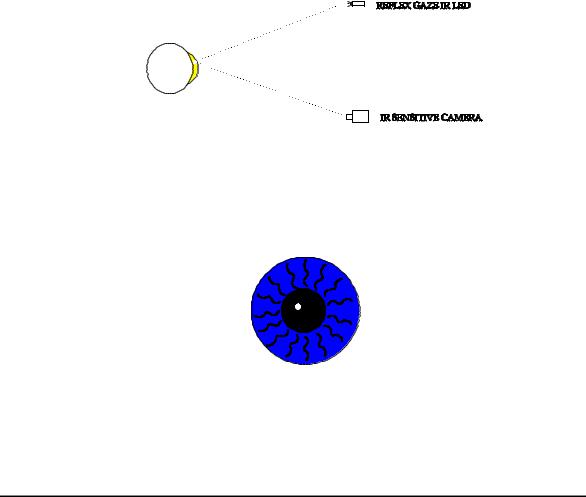
The HFA II - i uses two systems for measuring patient fixation: the standard Heijl-Krakau blindspot monitoring and the IR Gaze Tracking System. Both methods can be used, either together or alone, or they can both be turned off, as required. This description covers the IR Gaze Tracking System.
The direction of a patient's gaze is determined in two steps: first, a reflex marker is established on the corneal surface; and second, the location of the pupil center is determined.
Gaze tracking is initialized in the following manner when a selected test is first started:
The patient is asked to fixate on the central illumination LED. Gaze tracking turns on the reflex gaze IR LED located just under the diamond fixation pattern and turns off eye illumination briefly . Light from the LED is reflected off the cornea, and back to the IR sensitive camera (Figure 1-1). The majority of the cornea appears black except for the reflected spot. This image is digitized and stored in memory. The reflected spot is referred to as the reflex marker
(Figure 1-2). Because the corneal surface is rounded, the reflex marker will move very little even if the patient's eye rotates, and thus the marker becomes a (relatively) stationary reference point.
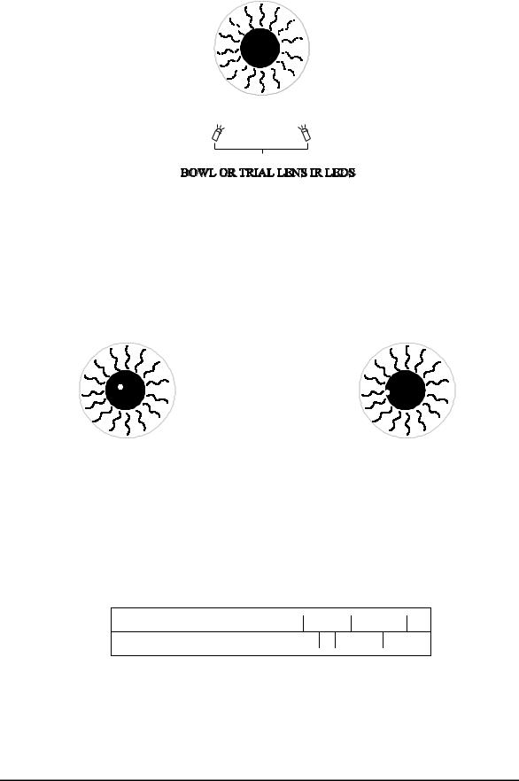
Next, the system locates the pupil center by illuminating the entire eye with the two IR LEDs located either in the bottom of the bowl, or in the trial lens holder (when in the raised position). The iris appears bright with a dark pupil (Figure 1-3). This image is also digitized and stored in memory. It is the relationship between the location of the reflex marker on the cornea and the location of the pupil center that determines fixation (Figure 1-4).
Note - When gaze tracking is being initialized, it appears as repetitive "strobing" when viewed by the operator via the video insert on the HFA II - i monitor.
During a test, each time a spot is projected into the bowl, the locations of the reflex marker and the center of the pupil are compared to the initial images stored in memory. If the patient is fixating correctly, the positional relationship between the reflex marker and the pupil center will be the same as that of the stored images (Figure 1-4). If the patient is off fixation, the positional relationship between the reflex marker and the pupil center will be different, as in Figure 1-5. The greater the misalignment, the higher the mark on the Gaze Graph (Figure 1-6).
(continued)
Confidential and Proprietary
52235C1105 |
1 - 11 |
Field Service Guide |
General Information |
Humphrey Field Analyzer II - i |
Spikes that appear on the Gaze Graph (Figure 1-6) are analyzed as follows:
PUpward spikes indicate that the patient has lost fixation;
•a spike that reaches the top horizontal line (or higher) indicates 10 degrees (or more) off fixation;
•a spike that extends halfway to the top line indicates 5 degrees off fixation.
PDownward spikes indicate as follows:
•a short spike downward indicates that the gaze at that time cannot be determined by the software.
•a long spike downward indicates that the patient blinked at the time fixation was checked.
The absence of marks on the graph indicates proper fixation.
Possible problems associated with the gaze tracking system are reflections from the trial lens, fingerprints on the trial lens, an improperly aligned trial lens holder, an improperly calibrated or aligned Gaze Tracking box, and excessive patient tearing.
FIGURE 1-1. Location of Corneal Reflex Marker
FIGURE 1-2. Corneal Reflex marker Location Digitized and Stored in Memory
Confidential and Proprietary
Field Service Guide |
1 - 12 |
52235C1105 |
Humphrey Field Analyzer II - i |
General Information |
FIGURE 1-3. Determining the Pupil Center
FIGURE 1-4. Patient Fixating – Corneal |
FIGURE 1-5. Patient Not Fixating – |
Reflex Marker and Pupil in Proper |
Corneal Reflex Marker and Pupil Not in |
Relationship |
Proper Relationship |
FIGURE 1-6. Gaze Graph
Confidential and Proprietary
52235C1105 |
1 - 13 |
Field Service Guide |

General Information |
Humphrey Field Analyzer II - i |
1.7.3Head Tracking / Auto Pupil / Vertex Monitoring
These three features are dependent on the Gaze Tracking system. If Gaze Tracking has successfully initialized, any of these three features can be utilized.
Head Tracking
The Head Tracking feature is designed to lessen the appearance of a trial lens artifact image when the patient's eye is off center in relation to the center of the trial lens holder. The intent is to reduce the possibility of inducing an arc-like defect or ring scotoma in the patient's field test results.
Head Tracking is active when the trial lens holder is in the up position and Head Tracking has been set to ON in the setup menu. The Head Tracking feature will track the center of the eye in relation to the trial lens holder. If the patient's eye moves from the center of the trial lens holder by more than 3 mm for more than one consecutive sample, the head tracking feature will gently move the chinrest and headrest to automatically reposition the patient's eye in the center of the trial lens holder. The tracking will stop if the eye doesn’t follow the correction. Tracking begins when the test is started. This feature will operate properly only if the patient properly rests on the chinrest.
Auto Pupil
When the Auto Pupil feature is set to ON in the setup menu, the gaze monitoring system will determine the size of the patient's pupil to the nearest 0.5 mm at the beginning of each test (during initialization of gaze tracking), and will automatically enter that information into the Patient Data information screen, marked Auto (*).
Vertex Monitoring
The Vertex Monitoring feature is designed to lessen the appearance of a trial lens artifact image when the patient's head moves backwards (away from) the trial lens holder. The intent is to reduce the possibility of inducing an arc-like defect or ring scotoma in the patient's field test results. Vertex Monitoring will alert the operator (via a double beep) if the patient's eye moves more than 7 mm away from its original position for any one measurement. (The sample rate is once every question.)
Vertex distance measurement is obtained during gaze initialization. During gaze initialization, the two IR LEDs on the trial lens holder appear as two dots of light on the corneal surface. (Refer to 1.7.2 Gaze Tracking for a complete description.) The distance between these two dots will decrease as the head moves away from its original position. If the distance exceeds the software limits, an alert will sound. The test continues, and a popup window appears allowing the user to reinitialize, continue without reinitializing, or turn off vertex monitoring.
Confidential and Proprietary
Field Service Guide |
1 - 14 |
52235C1105 |

Humphrey Field Analyzer II - i |
General Information |
1.7.4HFA II - i Light Intensity Fundamentals
The HFA II - i uses one detector mounted at the end of the turret to measure both spot and bowl intensities. The projection lamp voltage is controlled by software to set maximum stimulus brightness. This means that the lamp can be operated at a lower voltage when the lamp is new; and as it ages, more voltage is applied in order to maintain the same level of brightness. This increases lamp life expectancy and reduces power consumption.
During light intensity calibration, the projection calibration value is stored in memory and set as close as possible to obtain 929 Ft-L or 10,000 asb of light output. The background lights are fluorescent and the calibration values are set as close as possible to obtain 2.92 Ft-L or 31.5 asb. During calibration, light attenuation is measured at 175 different points on each of the two ND wedges, and the results are stored in memory. The two ND wedges are used in combination to obtain the desired brightness of the projected spot. The duration of the spot is 200 ms and is controlled by the software operating the shutter, located between the projection lamp and the ND wedges.
During the power-on sequence, the bowl intensity is set to the calibrated value (2.92 Ft-L or 31.5 asb). The brightness detector is then pointed at a black patch located on the inside of the front cover, the shutter is closed, and a measurement is made by the detector. This establishes the zero asb reference. Next, the shutter is opened, and a spot projected on the bowl approximately 35E above center is measured by the detector. The projection voltage is adjusted to match the calibration value stored in memory. This measurement sets the maximum brightness level (10,000 asb, or 0 dB). These two measurement points determine the slope of the light from dark to maximum brightness.
If the measured intensity varies from that stored during calibration, the lamp voltage is adjusted and measured again. This continues until the stored intensity and measured intensity match. If the voltage is adjusted above 10 V, the test will fail and a projection lamp error message will appear on the screen. If the test does not fail, ten different points on each ND wedge are measured and compared with their stored values. If these values deviate more than ±.5 dB from the stored values, the test will fail and a wedge failure error message will be displayed.
1.7.5Comparing HFA II and HFA II - i
Hardware -
The HFA II - i version differs from the prior production version, the HFA II, in that significant upgrades have been made.
The HFA II - i uses an off-the-shelf CPU PCB featuring an Intel Celeron 433 MHz processor, while the HFA II uses a 20 MHz Motorola 68020-based processor. The new CPU PCB dramatically decreases the test processing time resulting in significant overall test time reduction. The HFA II - i CPU PCB contains 64 megabytes of DIMM memory while the HFA II has 4 megabytes of memory on the current CPU. The increase is significant in the ability to support software features planned for the future; in particular, the implementation of Ensemble. In
Confidential and Proprietary
52235C1105 |
1 - 15 |
Field Service Guide |
General Information |
Humphrey Field Analyzer II - i |
addition, the new board features components selected to ensure ease of parts availability, particularly integrated circuit components.
The HFA II - i CPU PCB uses an IDE hard drive controller. The HFA II CPU PCB uses a SCSI hard drive controller. The HFA II - i has an IDE hard drive while the HFA II uses a SCSI hard drive. Note that the two drives are not interchangeable.
Mouse/Glide Pad |
|
PS2 |
|
||
|
|
Mouse |
Keyboard |
|
PS 2 |
|
||
|
|
Keyboard |
Backplane |
|
PCI |
Board |
|
|
|
|
|
Backplane |
|
EISA |
Board |
|
Bus |
Intel Celeron Processor
System Memory 64MB
Flash Memory
(Boot Data)
NOVRAM/Clock
EIDE Controller
Floppy Controller
Serial Interface
Printer Interface
J 9 |
|
|
Serial |
|
|
|
Port |
J 10 |
|
|
Serial |
|
|
|
Port |
J 7 |
|
|
Parallel |
|
|
Printer |
|
|
|
|
Port |
J 3 |
|
Hard Drive |
|
MO Drive |
|
|
||
|
|
USB |
|
USB |
Ethernet |
|
|
Network |
||
Device |
|
|
|
|||||
|
|
Port |
|
|
|
|||
|
|
|
|
|
|
|
||
USB |
|
|
|
|
|
|
|
Floppy |
|
USB |
J 4 |
|
|
Disk |
|||
Device |
|
|
|
|||||
|
|
|
|
|
|
|
||
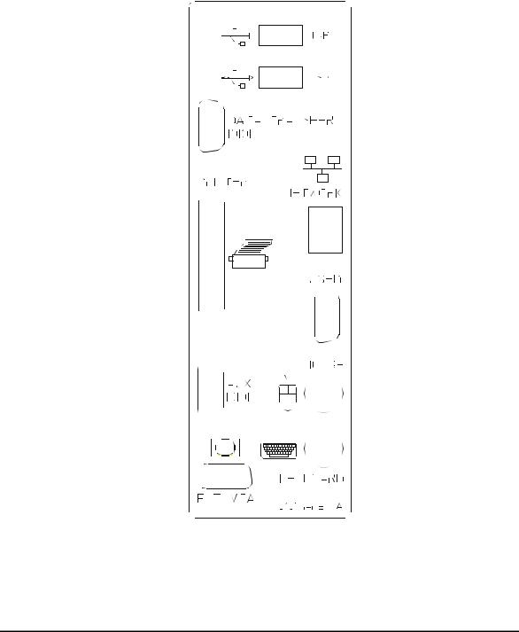
FIGURE 1. CPU PCB Functions and Interconnects
Confidential and Proprietary
Field Service Guide |
1 - 16 |
52235C1105 |

Humphrey Field Analyzer II - i |
General Information |
Many of the unique functions that the HFA II CPU PCB supported are now included in the HFA II - i Backplane PCB. The functions of the Backplane PCB include; the patient switch, touch screen, camera frame grabber, and video.
FIGURE 2. Backplane PCB Functions and Interconnects
The DAT streamer tape of the HFA II has been replaced with a magneto-optical medium reader in the HFA II - i. Besides reducing cost, the new HFA II - i drive provides greater long-term storage of large patient files.
For EMI considerations, the HFA II - i CPU PCB and Backplane PCB are housed in a metal enclosure. The enclosure is bolted the chassis in the location of the HFA II CPU PCB.
To accommodate the enclosure the rear cover was redesigned. The rear cover does not make use of 1/4 turn fasteners.
Confidential and Proprietary
52235C1105 |
1 - 17 |
Field Service Guide |
General Information |
Humphrey Field Analyzer II - i |
The HFA II - i has a larger capacity power supply to provide the additional Vcc power required for the HFA II - i.
The HFA II - i uses a new Motor Driver Board (MDB). The new MDB will ensure longer component availability.
FIGURE 3. HFA II - i Interconnects
Confidential and Proprietary
Field Service Guide |
1 - 18 |
52235C1105 |
 Loading...