


Primo Star
Operating manual
Bedienungsanleitung
Mode d’emploi
Instrucciones de manejo
Инструкция по применению
操作手册

g
ç
p
у
中文
Carl Zeiss Copyright Primo Star
Knowledge of this manual is required for the operation of the instrument. Would you therefore
please make yourself familiar with the contents of this manual and pay special attention to hints concerning
En
safe operation of the instrument. The specifications are subject to change; the manual is not covered
lish Deutsch
by an update service. Unless expressly authorized, forwarding and duplication of this document,
as well as utilization and communication of its contents are not permitted. Violations will entail an
obligation to pay compensation. All rights reserved in the event of granting of patents or registration of a utility
model.
Die Kenntnis dieser Anleitung ist für die Bedienung des Gerätes erforderlich. Bitte machen Sie sich deshalb
mit dem Inhalt vertraut und befolgen Sie besonders Hinweise, die den sicheren Umgang mit dem Gerät
betreffen. Änderungen im Interesse der technischen Weiterentwicklung bleiben vorbehalten; das Handbuch
unterliegt nicht dem Änderungsdienst. Weitergabe sowie Vervielfältigung dieser Unterlage, Verwertung und
Mitteilung ihres Inhalts sind nicht gestattet, soweit nicht ausdrücklich zugestanden. Zuwiderhandlungen
verpflichten zu Schadenersatz. Alle Rechte für den Fall der Patenterteilung oder Gebrauchsmuster-Eintragung
vorbehalten.
L’utilisation de l'appareil suppose la bonne connaissance du présent mode d’emploi. Nous vous prions par conséquent
Fran
de lire attentivement les informations contenues dans ce document et de respecter notamment les consignes relatives
à la sécurité d’utilisation. Le fabricant se réserve le droit d’apporter des modifications techniques en fonction de
l’évolution des technologies. Ces modifications ne sont pas automatiquement prises en compte dans le mode d'emploi
ais
qui accompagne chaque appareil. Toute divulgation, reproduction ou publication du présent document, même
partielle, est interdite sans notre autorisation écrite. Toute infraction donne droit au versement de dommages et
intérêts. Tous les droits sont réservés en cas de délivrance d’un brevet ou de dépôt d’un modèle d'utilité.
El manejo de este equipo presupone el conocimiento de las presentes instrucciones. Por eso le rogamos
Es
familiarizarse con su contenido y observar en particular las indicaciones que se refieren al manejo seguro del mismo.
Nos reservamos el derecho a modificaciones en interés del desarrollo técnico; el manual no está sujeto al servicio de
añol
actualización. Sin nuestro consentimiento expreso no se autoriza ni la entrega y reproducción de este manual, ni el
aprovechamiento y la comunicación de su contenido. Cualquier contravención implica el pago de una
indemnización. Reservados todos los derechos para el otorgamiento de patentes o el registro de modelos de
utilidad.
Знание данной инструкции необходимо для использования прибора. Поэтому необходимо ознакомиться
Р
с ее содержанием и особенно следовать указаниям, касающихся безопасного обращения с прибором.
сский
Фирма оставляет за собой право на изменения в интересах технического усовершенствования;
руководство не подлежит изменениям. Передача и тиражирование данных документов, использование и
сообщение их содержания не допускаются без особого
возмещение убытков. Фирма оставляет за собой право на выдачу патента или регистрацию
зарегистрированной модели.
版 权
操作本仪器必须先阅读本手册内容。因此请务必熟悉本手册内容,尤其要遵从有关仪器正确操作的注意事项。技
术可能会有更新,此手册不含升级服务。未经授权禁止复制,利用和转载本手册内容。如有违背必须承担相应赔
偿责任。保留所有申请专利或者样品注册权利。
Issued by: Carl Zeiss MicroImaging GmbH
P.O.B. 4041, 37030 Göttingen, Germany
Phone: +49 (0) 551 5060 660
Fax: +49 (0) 551 5060 464
E-Mail: micro@zeiss.de
www.zeiss.de
Number of this manual: B 46-0071 v
Date of issue: Version 7, 03/01/2006
разрешения. В случае нарушений полагается
2 B 46-0071 v 03/06

g
Primo Star Contents Carl Zeiss
CONTENTS
Page
lish
1 Notes on Instrument Safety.............................................................................................. 4
1.1 General safety notes............................................................................................................. 4
1.2 Instrument safety and EMC .................................................................................................. 4
1.3 Unpacking, transportation, storage....................................................................................... 5
1.4 Disposal................................................................................................................................ 5
1.5 Use....................................................................................................................................... 5
1.6 Notes on warranty................................................................................................................ 7
2 Description ......................................................................................................................... 8
2.1 System overview................................................................................................................... 8
2.2 Total view........................................................................................................................... 10
2.3 Intended use ...................................................................................................................... 11
2.4 Instrument description and main features ........................................................................... 11
2.5 Objectives........................................................................................................................... 12
3 Start-Up and Operation .................................................................................................. 13
3.1 Starting up the microscope................................................................................................. 13
3.2 Controls ............................................................................................................................. 14
3.3 Operating the microscope .................................................................................................. 16
3.3.1 Setting interpupillary distance and viewing height .............................................................. 16
3.3.2 Compensating for ametropia and inserting the eyepiece pointer......................................... 16
3.3.3 Adjusting transmitted-light brightfield on the Full Köhler microscope.................................. 17
3.3.4 Adjusting transmitted-light brightfield on the Fixed Köhler microscope ............................... 18
3.3.5 Adjusting transmitted-light phase contrast or transmitted-light darkfield............................. 19
3.4 Converting the microscope................................................................................................. 20
3.4.1 Changing the tube ............................................................................................................. 20
3.4.2 Inserting color filters........................................................................................................... 20
3.4.3 Replacing the 6V 30W halogen lamp or the LED illumination.............................................. 21
3.4.4 Changing objectives ........................................................................................................... 21
3.4.5 Installing/removing the illuminating mirror.......................................................................... 22
3.4.6 Installing a camera.............................................................................................................. 23
En
4 Care and Troubleshooting .............................................................................................. 25
4.1 Instrument care .................................................................................................................. 25
4.2 Troubleshooting ................................................................................................................. 26
5 Appendix.......................................................................................................................... 27
5.1 Technical data .................................................................................................................... 27
B 46-0071 v 03/06 3

g
Carl Zeiss Notes on Instrument Safety Primo Star
1 NOTES ON INSTRUMENT SAFETY
En
1.1 General safety notes
lish
Please read this Operating Manual carefully before starting up the microscope.
If you need supplementary information, contact Carl Zeiss Service or an authorized agency.
To ensure safe operation and troublefree function of the microscope, strictly observe the precautions and
warnings given in this manual.
These are set off herein as follows:
CAUTION
This symbol indicates a possible hazard to the user of the instrument.
CAUTION
This symbol indicates a possible hazard to the instrument or system.
CAUTION
Disconnect the plug-in power unit from line power before opening the microscope!
NOTE
This symbol refers you to advice that you must observe under all circumstances.
1.2 Instrument safety and EMC
The Primo Star microscope has been designed, produced and tested in compliance with the standards
DIN EN 61010-1 (IEC 61010-1) and IEC 61010-2-101 "Safety requirements for electrical equipment for
measurement, control and laboratory use “.
The Primo Star microscope meets the requirements of the EC Directive 98/79/EC Annex 1 and carries the
mark.
Radio-noise suppression in compliance with EN 55011 Class B
Noise immunity in compliance with DIN EN 61326
The instruments are disposed of in compliance with the WEEE Directive 2002/96/EC.
4 B 46-0071 v 03/06

g
Primo Star Notes on Instrument Safety Carl Zeiss
1.3 Unpacking, transportation, storage
Please observe the following safety notes for unpacking, transportation and storage of the microscope:
− The microscope is supplied packed to commercial standards in a plastic case with cardboard
packaging; use the original packaging only for any transportation.
− Retain the original packaging for longer storage or return to the manufacturer.
− When unpacking the equipment, verify that all parts specified on the delivery note are present.
− Keep transport and storage temperatures as specified in Technical Data.
− Set up the microscope on a stable worktable with solid and smooth tabletop.
− Do not touch optical surfaces.
1.4 Disposal
Please observe the following safety notes for the disposal of the microscope:
Defective microscopes should not be disposed of with household waste; dispose of them in
compliance with the provisions of the law.
lish
En
1.5 Use
The microscope including its original accessories must not be used for microscopic techniques other than
those described in this Operating Manual.
Please observe the following safety notes when using the microscope:
The manufacturer cannot assume any liability for other applications, including those of
individual modules or single components. This also applies to any service or repair work that is
not carried out by authorized service personnel. In case of non-compliance, all warranty claims
shall be forfeited.
The microscope may only be operated by trained personnel who must be aware of the possible
dangers involved with microscopy and the particular application concerned. The microscope
may only be operated if set up on a stable, solid and smooth surface.
The stereomicroscope is a high-precision instrument that can be impaired in its performance or
even be destroyed when handled improperly.
B 46-0071 v 03/06 5

g
Carl Zeiss Notes on Instrument Safety Primo Star
The microscope is equipped with a plug-in power unit allowing line voltages to be used in the
En
lish
range between 100 and 240 V ± 10%, 50/60 Hz, without the need for changing the voltage
setting on the instrument.
The plug-in power unit meets the requirements of Protection Class II (with protective
insulation). If its casing is damaged, put the plug-in power unit out of operation. The
microscope may be operated only with the supplied plug-in power unit.
If it is determined that protection measures are no longer effective, the instrument must be
switched off and safeguarded against inadvertent operation. Please contact a Zeiss service
agency or the Carl Zeiss Microscopy Service to repair the instrument.
− Always disconnect the power cable, before opening the instrument and changing the lamp
or LED source.
− Wait for the lamp to cool down before replacing it and do not touch the new bulb.
− The instrument may only be opened by qualified specialists or service staff.
− The operation of the instrument in explosion-risk environments is not allowed.
®
Make sure to read the safety notes provided with Immersol 518 N
immersion oil.
Immersion oil irritates the skin. Avoid any contact with skin, eyes and clothing.
After skin contact, wash the oil off with plenty of water and soap.
After eye contact, immediately rinse the eye with plenty of water for at least five minutes.
If the irritation persists, consult a specialist.
Proper disposal of immersion oil: Take care to ensure that immersion oil does not enter surface
water or the sewage system.
The microscope is not equipped with special devices for the protection from substances that
are corrosive, potentially infectious, toxic, radioactive, or other substances that could be
hazardous to health. Make sure to observe all legal regulations, particularly the relevant
national accident prevention regulations when handling such substances.
− Before any transport of the instrument, switch it off and let it cool down (hot surface at the
bottom of the instrument).
− Operate the device only on a hard, non-combustible support.
− The plug-in power unit must not get in contact with moisture.
6 B 46-0071 v 03/06

g
Primo Star Notes on Instrument Safety Carl Zeiss
1.6 Notes on warranty
The Primo Star Microscope including its original accessories must not be used for microscopic techniques
other than those described in this Operating Manual. The manufacturer cannot assume any liability for
other applications.
Please note the following information on warranty for the Primo Star Microscope:
− The manufacturer guarantees that the microscope is free of material or manufacturing defects when
delivered.
− Possible defects must be notified to us immediately and steps be taken to minimize damage.
− If notified of such a defect, the manufacturer is obligated to rectify it at his discretion, either by
repairing the instrument or delivering an intact replacement.
− No guarantee is provided for defects caused by natural wear (wearing parts in particular) and improper
use.
− The instrument manufacturer shall not be liable for damage caused by faulty operation, negligence or
any other tampering with the microscope, particularly the removal or replacement of microscope
components, or the use of accessories from other manufacturers.
Unauthorized tampering with the instrument shall lead to a forfeit of all warranty claims.
lish
En
B 46-0071 v 03/06 7

g
Carl Zeiss Description Primo Star
2 DESCRIPTION
En
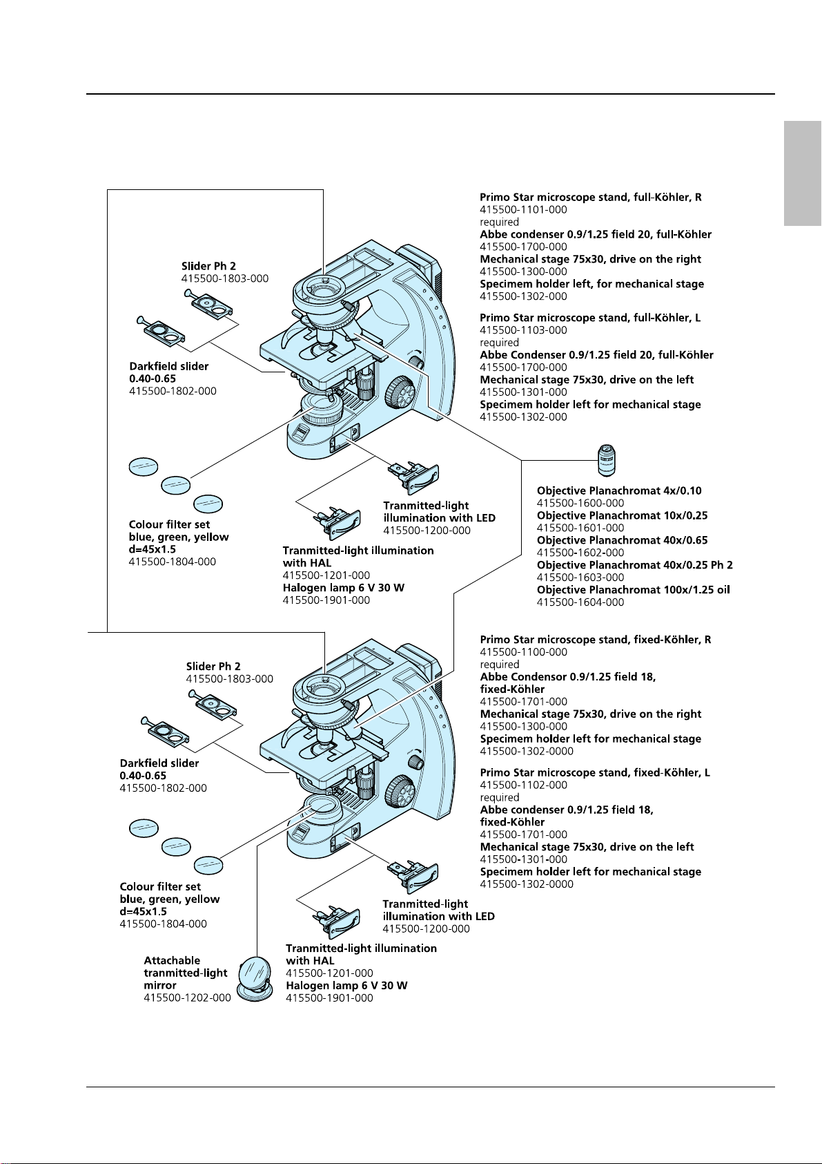
2.1 System overview
lish
8 B 46-0071 v 03/06
g
Primo Star Description Carl Zeiss
lish
En
B 46-0071 v 03/06 9

g
Carl Zeiss Description Primo Star
2.2 Total view
En
lish
1 Eyepiece
2 Binocular head
3 Tube
4 Carrying handle
5 Plug-in power unit
6 Stand
7 ON/OFF switch;
illumination
intensity
8 Illumination
module
9a Luminous-field
diaphragm,
adjustable
9b Luminous-field
diaphragm, fixed
10a Condenser carrier,
Full Köhler
10b Condenser carrier,
Fixed Köhler
11a Abbe condenser,
Full Köhler
11b Abbe condenser,
Fixed Köhler
12 Objective
13 Microscope stage
14 Objective
nosepiece
Fig. 1 Total view
10 B 46-0071 v 03/06

g
Primo Star Description Carl Zeiss
2.3 Intended use
The Primo Star microscope is a universally applicable light microscope primarily designed for the
examination of cell and tissue cultures as well as sediments in culture flasks, Petri dishes and microplates.
Typical applications:
Examination of blood and tissue samples from the human body, observation of intracellular
processes on living cell cultures, cell-cell interactions, motility, growth, potential measurement,
detection of medical drugs, microinjection and in vitro fertilization.
When handling hazardous substances, observe the instructions on intended operation, correct use and
statutory safety precautions.
2.4 Instrument description and main features
The Primo Star is a transmitted-light microscope of compact design with a small footprint.
Beside the high-resolution, infinity-corrected objectives and the important microscopy techniques, such as
brightfield, darkfield and phase contrast, the microscope is optionally available with a camera port for
photo and video documentation.
The major features of the microscope include:
− Modular illumination through 6V 30W halogen lamp, LED illumination or illuminating mirror.
− Integrated fixture for external power supply and cable (incl. cable with multi-standard plug and
country-specific plug adapters)
lish
En
− Plastic-coated carrying handle integrated in stand for installation, uninstallation and transport
− Blue, light-intensity indicators installed on both sides and well visible from a distance
− Stand in "Full Köhler" or "Fixed Köhler" design
− Convenient coaxial coarse and fine focusing drive, smoothness of coarse focusing drive being
adjustable
− Mechanical stage 75×30 left/right with specimen holder, stage controls optionally on the right or left
− Space-saving, continuously adjustable illumination module optionally with halogen or LED source
− "Full Köhler" or "Fixed Köhler" Abbe condensers for brightfield, darkfield and Ph 2 phase contrast
− Backward inclined quadruple objective nosepiece with W 0.8 lens thread running on ball bearing
− Infinity-corrected "Plan-ACHROMAT" objectives with magnifications of 4x, 10x, 40x and 100x/Oil for
brightfield, darkfield and Ph 2 phase contrast Ph 2 (40x/Ph2) as well as for oil immersion applications
(100x/Oil)
− Binocular tube or binocular phototube (50% vis, 50% doc) with ergonomically favorable tube angle of
30° with adjustable interpupillary distance and viewing height
− 10× focusing eyepieces for field-of-view numbers 18 or 20, suitable for spectacle wearers
B 46-0071 v 03/06 11

g
Carl Zeiss Description Primo Star
2.5 Objectives
En
The objectives are the optical heart of the microscope. The objectives may be labeled as follows:
lish
Plan-ACHROMAT 10×/0.25 ∞/-.
where:
10× Objective magnification,
With a defined color ring on the
objective being assigned to each
magnification step (Carl Zeiss color code)
0.25 Numerical aperture
∞ Infinite mechanical tube length
− Usable with cover slip thickness D = 0 or
0.17 mm
or
0.17 Usable with cover slip thickness
D = 0.17 mm
Other labels:
Oil Oil immersion objective
Fig. 2 Objective
Ph 2 Phase contrast objective with green
inscription and phase stop Ph 2
Objective magnification multiplied by eyepiece magnification results in overall visual magnification, e.g.
10 x 10 = 100x.
Numerical aperture multiplied by 1000, e.g. 0.25 × 1000 = 250×, presents the maximum useful
magnification; there is no resolution for further details above that limit.
When immersion objectives are used, the air between the cover slip and the objective is replaced by a
liquid, which in most cases is immersion oil. The plastic oiler containing 5 ml of immersion oil is
particularly suitable for this purpose.
Because of their short working distances, the 40×, 40x/Ph 2 and 100x/Oil objectives are equipped with
resilient mounts for specimen protection.
12 B 46-0071 v 03/06

g
Primo Star Start-Up and Operation Carl Zeiss
3 START-UP AND OPERATION
3.1 Starting up the microscope
Before installing and starting up the microscope, be sure to carefully read and observe the
notes on instrument safety (see Section
1).
Do not touch optical surfaces when unpacking the microscope to avoid fingerprints!
The microscope is supplied completely assembled and inclusive of accessories packed to commercial
standards. Additionally ordered components, such as sliders or transmitted-light equipment with
illuminating mirror, are packed separately.
• Remove the microscope from the transport case and place it onto the worktable.
Retain the original packaging for storage of the instrument in longer periods of non-use or for
return to the manufacturer.
• Remove the plug-in power unit (
Fig. 3/2) from
its storage fixture on the back wall of the
microscope.
• Replace the installed power outlet adapter by
one of the supplied country-specific adapters
Fig. 3/4), if necessary. To this end, pull off the
(
attached adapter and plug on the desired
adapter.
lish
En
• Connect the plug-in power unit to a power
outlet.
• If the plug-in power unit cannot be plugged
into the chosen power outlet because of limited
space, replace the power outlet adapter by the
supplied IEC adapter (
Fig. 3/3). This allows the
plug-in power unit to be put flat onto the
tabletop and connected to the power outlet
through a country-specific appliance cable.
When using the IEC adapter, the plug-in power unit can be fixed to the back wall of the
microscope stand by means of the supplied two self-adhesive hooks and the Velcro
• Turn on the microscope with rotary switch (
Fig. 3/5) and adjust the illumination to the desired
Fig. 3 Starting up the microscope
®
strip.
intensity.
The selected intensity is indicated in five steps by the blue light-emitting diodes (
Fig. 3/1) arranged on
both sides of the stand.
• At the end of the microscopic examinations, turn the microscope off with the rotary switch and cover
it with the dust cover.
• The smoothness of the coarse focusing drive (
Fig. 4/18) is factory-adjusted. However, you can readjust
it when required.
B 46-0071 v 03/06 13

g
Carl Zeiss Start-Up and Operation Primo Star
3.2 Controls
En
lish
Fig. 4 Controls
14 B 46-0071 v 03/06

g
Primo Star Start-Up and Operation Carl Zeiss
Legend to Fig. 4:
1 Eyepieces
2 Binocular body of the tube
3 Illumination-intensity indicators
4 Rotary knob for switch ON/OFF and adjustment of illumination intensity
5 Fine focusing drive (right side)
6 Coarse focusing drive (right side)
7 Control knob for X travel of mechanical stage
8 Control knob for Y travel of mechanical stage
9 Condenser clamp screw
10a Knurled ring for adjustment of luminous-field diaphragm (with Full Köhler equipment only)
10b Luminous-field diaphragm (fixed in Fixed Köhler equipment)
11a Condenser entering screws (in Full Köhler equipment: knurled screws)
11b Condenser centering screws (in Fixed Köhler equipment: Allen screws)
12 Spring lever of specimen holder
13 Knurled ring of objective nosepiece
14 Lever for the adjustment of the aperture diaphragm of the condenser
15 Knurled knob for vertical adjustment of condenser
16 Coarse focusing drive (left side)
17 Fine focusing drive (left side)
18 Knurled ring for adjusting the smoothness of the coarse focusing drive
lish
En
B 46-0071 v 03/06 15

g
Carl Zeiss Start-Up and Operation Primo Star
3.3 Operating the microscope
En
lish
3.3.1 Setting interpupillary distance and viewing height
• Swing the eyepiece tubes symmetrically slightly
toward or away from one another to adjust the
distance between the tubes to your individual
interpupillary distance (
Fig. 5).
The adjustment of the interpupillary distance is
correct when you see only one round image while
Fig. 5 Setting the interpupillary distance
looking through the two eyepieces!
• Swivel the eyepiece tubes fully up (
down (
Fig. 6/B) to adjust the viewing height to
Fig. 6/A) or
your individual requirements.
Fig. 6 Adjusting the viewing height
3.3.2 Compensating for ametropia and inserting the eyepiece pointer
The eyepieces (
over rubber eyecups (
Fig. 7/3) are equipped with fold-
Fig. 7/1: pulled out; Fig. 7/2:
folded over).
Both eyepieces are suitable for spectacle wearers.
Additionally, they contain a focusing ring for the
compensation of defective vision. The provided
diopter scale serves to facilitate finding the correct
setting.
The eyepiece pointer can be inserted in one
eyepiece, when required.
To this end, follow this procedure:
• Use Allen key SW 1 mm to loosen grub screw
(
Fig. 7/6) on the binocular body from the
bottom; remove the eyepiece.
• Unscrew the stop (
Fig. 7/5) by hand from the
eyepiece.
• Insert the eyepiece pointer (
Fig. 7/4) into the
eyepiece (with the coated side facing your
eyes). Screw in the eyepiece stop again.
• Put the eyepiece into the tube and fix it with
Fig. 7 Inserting the eyepiece pointer
the grub screw.
16 B 46-0071 v 03/06

g
Primo Star Start-Up and Operation Carl Zeiss
• Turn the focusing ring of the eyepiece (Fig. 7/3) to focus on the triangular figure of the eyepiece
pointer.
• Put the specimen onto the mechanical stage. Look at the specimen through the eyepiece with the
eyepiece pointer and focus on the microscopic image by turning on the focusing drive.
• When in the above-mentioned eyepiece both microscopic image and eyepiece pointer appear sharply,
focus the image for the second eye by turning the focusing ring of the second eyepiece.
Having done so, both microscopic images inclusive of the eyepiece pointer are focused.
Afterwards, you should focus on the specimen only by adjusting the focusing drive.
3.3.3 Adjusting transmitted-light
brightfield on the Full Köhler
microscope
• First, place a contrasty specimen slide with the
0.17 mm cover slip being on top in the
specimen holder of the mechanical stage. Fix
the slide by means of the spring lever
Fig. 4/12).
(
lish
En
• If the microscope stand is equipped with a
phase or dark-filed slider, pull this slider out to
the left as far as it will go.
• Turn rotary knob (
Fig. 8/1) on microscope stand
to adjust the illumination intensity.
• Move the Abbe condenser up to the top
mechanical stop by turning knurled knob
Fig. 4/15); set the control lever of the aperture
(
diaphragm (
Fig. 4/14) to mid-position.
The knurled knob for vertical
adjustment of the condenser is at the
left of the microscope, if you use the
mechanical stage 75x30 with drive on
the right, it is at the right, if the stage
controls are on the left.
• Turning at the knurled ring (
Fig. 8/6) of the
nosepiece, swing the 10x objective into the
light path.
• On the binocular tube (
Fig. 8/7), first look
through one eyepiece and turn the focusing
Fig. 8/2) to focus on the specimen.
drive (
Fig. 8 Adjusting transmitted-light
brightfield
• Then, readjust the focus for the other eye, if necessary, by turning the eye lens of the focusing
eyepiece.
• Close the luminous-field diaphragm (
of view (
Fig. 8/A).
Fig. 8/3) until it becomes visible (even if not in focus) in the field
B 46-0071 v 03/06 17

g
Carl Zeiss Start-Up and Operation Primo Star
• Turn the knurled knob for vertical adjustment of the condenser (Fig. 4/15) until the edge of the
En
lish
luminous-field diaphragm appears sufficiently sharp (
• Center the image of the luminous-field diaphragm using both centering screws (
condenser (
Fig. 8/D).
(
Fig. 8/C). Then, open the diaphragm until it just disappears from the field of view
Fig. 8/B).
Fig. 8/5) of the
• To adjust the aperture diaphragm (contrast), remove one eyepiece from the tube and look through the
tube with your naked eye. Swing lever (
2/3 ... 4/5 of the diameter of the exit pupil of the objective (
Fig. 8/4) to adjust the aperture diaphragm to approximately
Fig. 8/E). In most applications, this
aperture diaphragm setting provides optimum contrast at almost ideal resolution, and is therefore the
best compromise for the human eye.
• Insert the eyepiece back in the tube.
Specimen field size and objective aperture change after every objective change. Therefore,
repeat the adjustment of luminous-field diaphragm and aperture diaphragm to obtain
optimum results.
3.3.4 Adjusting transmitted-light brightfield on the Fixed Köhler microscope
The Primo Star Fixed Köhler Microscope is supplied factory-adjusted. Operation is restricted to a few
manipulations.
• Place the specimen in the specimen holder of the mechanical stage.
• If the microscope stand is equipped with a phase or dark-filed slider, pull this slider out to the left as
far as it will go.
• Adjust the desired magnification by swinging in the corresponding objective.
• Set the control lever of the aperture diaphragm of the condenser to the value of the selected
magnification (10x, 40x or 100x).
• Turn the rotary knob on the microscope stand to adjust the illumination intensity to a level pleasant
for observation.
If the condenser had been removed (e.g. for installing the illuminating mirror), make sure to
reinstall and center it by means of the two centering screws (for this, refer to Section
3.4.5).
18 B 46-0071 v 03/06

g
Primo Star Start-Up and Operation Carl Zeiss
3.3.5 Adjusting transmitted-light phase contrast or transmitted-light darkfield
lish
• First, adjust the microscope as you do for
brightfield.
• Turn the nosepiece to swing the phase-contrast
objective (40x/Ph 2) into the light path.
• Open the luminous-field diaphragm (
Fig. 9/3, if
adjustable) on the stand and open the aperture
diaphragm by means of control lever (
on Abbe condenser (
• If the phase-contrast slider (
Fig. 9/2).
Fig. 9/6) was not
Fig. 9/1)
factory-installed yet, first unscrew its screw
Fig. 9/7). Then, push the slider from the left
(
into the Abbe condenser and screw the screw
Fig. 9/7) back in again.
(
• Push the slider to the right as far as it will go to
move the phase stop into the light path.
• Move the control lever of the aperture
diaphragm to fully open it on the Full Köhler
model or set it to the PH mark on the Fixed
Köhler model.
• Adjust the illumination intensity as needed.
En
Fig. 9 Inserting the slider
• Check the centering of the phase stop
according to the drawing in
Fig. 10. To this end,
remove one eyepiece and replace it by the
eyepiece telescope.
• Center the phase stop, if necessary, (
Fig. 10/A)
by turning the two adjusting screws of the
slider (
SW 1.5 (
corresponds to that shown in
Fig. 9/5) by means of the two Allen keys
Fig. 9/4) until the phase stop image
Fig. 10/B.
• Afterwards, replace the eyepiece telescope by
the eyepiece again.
For darkfield applications, use the darkfield slider in place of the phase-contrast slider.
Fig. 10 Centering the phase stop
B 46-0071 v 03/06 19
g
Carl Zeiss Start-Up and Operation Primo Star
3.4 Converting the microscope
En
lish
Unplug the plug-in power unit from
line power before converting the
microscope.
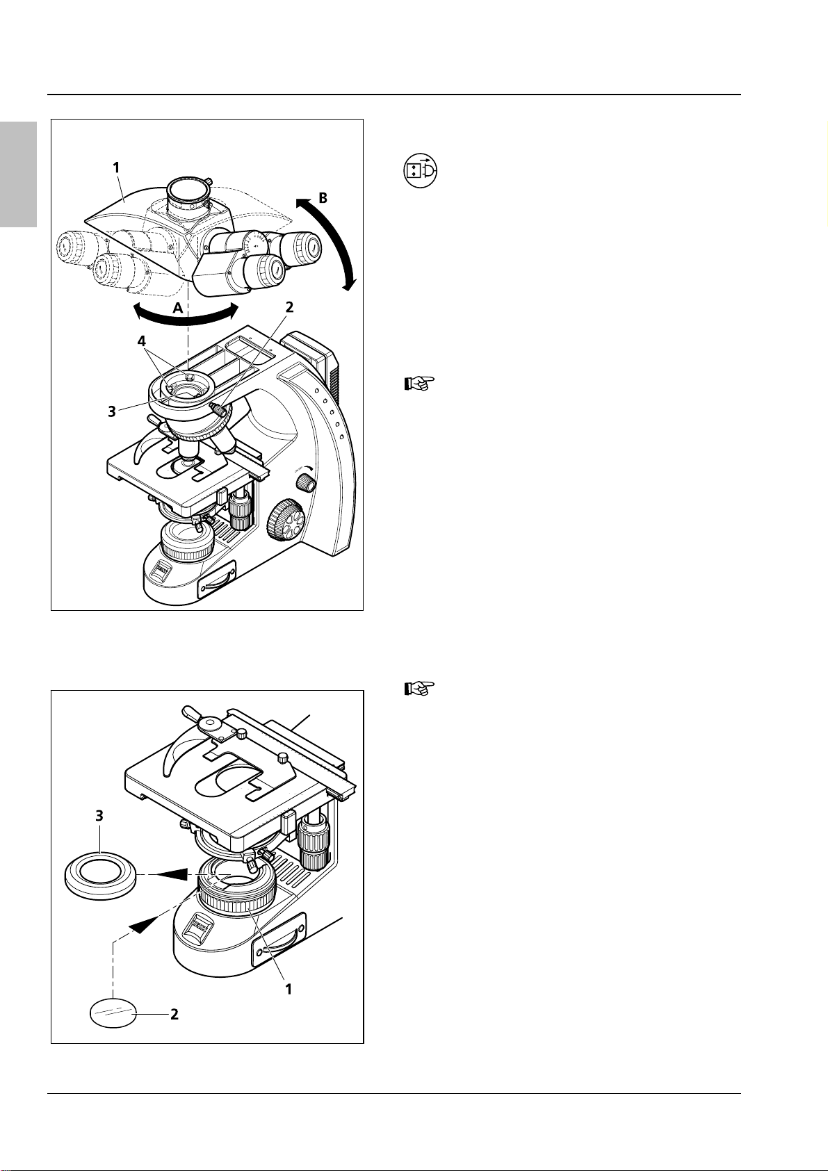
3.4.1 Changing the tube
Fig. 11 Changing the tube
• Loosen clamp screw (
installed tube (
approximately 90° (
side take it of upward (
For reasons of space, the tube may
Fig. 11/2), turn the
Fig. 11/1) clockwise by
Fig. 11/A) and on the right
Fig. 11/B).
also be clamped by the grub screw
with hexagonal socket head supplied
with the tube.
• Insert the tube to be installed, with the
eyepieces pointing to the right and its dovetail
mount slightly inclined, under the two holding
elements (
Fig. 11/4) in the stand.
• Then, place the tube horizontally onto the
stand. In doing so, the groove on the underside
of the tube must be located above the third
holding element (
Fig. 11/3) of the stand.
• Turn the tube counterclockwise by 45°
(eyepieces pointing frontward), align it to the
stand and tighten clamp screw (
For space-saving storage of the
Fig. 11/2).
microscope (e.g. in a cabinet) the tube
may also be rotated by 180° to the
back.
3.4.2 Inserting color filters
• Move the condenser carrier fully up by turning
the knurled screw for vertical adjustment
Fig. 4/15).
(
• Unscrew the cover cap (
luminous-field diaphragm (
Fig. 12/3) from the
Fig. 12/1).
• Put the desired filter – yellow, green or blue –
(
Fig. 12/2) onto the mounting surface of the
luminous-field diaphragm and screw the cover
cap back into place.
Fig. 12 Inserting a color filter
20 B 46-0071 v 03/06

g
Primo Star Start-Up and Operation Carl Zeiss
3.4.3 Replacing the 6V 30W halogen lamp or the LED illumination
Unplug the plug-in power unit from
the power outlet and allow for a
sufficient cool-down time of the
6V 30W halogen lamp before you
replace it.
lish
En
• Loosen both fastening screws (
illumination module (
Fig. 13/1 o 2). In doing so,
Fig. 13/3) of the
slightly press the screws against the spring and
turn them by 90°: Turn left screw clockwise and
right screw counterclockwise.
• Pull the illumination module (
Fig. 13/1 or 2) out
of the stand.
• If the stand is equipped with a 6V 30W halogen
lamp (
(
Fig. 13/4) from the lamp carrier and insert the
Fig. 13/2), remove the halogen lamp
new halogen lamp. Do not touch the new lamp
with naked fingers as this will reduce lamp life.
• If the stand is equipped with an LED source,
replace the complete illumination module
including the LED (
• Push the illumination module (
Fig. 13/1).
Fig. 13/1 or 2)
back into the stand and lock it by means of the
two screws (
Fig. 13/3). In doing so, slightly press
the screws against the spring and turn them by
90°: Turn left screw counterclockwise and right
screw clockwise.
Fig. 13 Replacing the 6V 30W halogen lamp
or the LED illumination module
3.4.4 Changing objectives
• Turn the focusing drive to move the mechanical
stage fully down.
• Turn the nosepiece (
objective to be changed (
Fig. 14/3) to move the
Fig. 14/1) into a lateral
position.
• Unscrew the objective and remove it
downward.
• Screw the desired objective (
nosepiece as far as it will go.
• If you intend to insert the objective in a lens
mount not used so far, remove the dust cover
from the corresponding mount of the
nosepiece.
Fig. 14/2) into the
Fig. 14 Changing an objective
B 46-0071 v 03/06 21

g
Carl Zeiss Start-Up and Operation Primo Star
3.4.5 Installing/removing the
En
illuminating mirror
lish
Fig. 15 Removing/installing the condenser
The mirror serves to illuminate the specimen if no
power outlet is available.
It can be used only in combination with the
Primo Star Fixed Köhler Microscope. For this
purpose, it is necessary to remove the condenser
and the condenser carrier insert.
Installing the illuminating mirror:
• Remove cover cap (
field diaphragm (
Fig. 15/6) from luminous-
Fig. 15/5).
• Using an Allen key, loosen the clamp screw
Fig. 15/2) of the condenser and the centering
(
screws (
Fig. 15/4) so that the condenser (Fig. 15/7) can
(
Fig. 15/3) of the condenser carrier
be removed frontward. Remove the condenser
Fig. 15/7).
(
• Unscrew clamp screw (
from condenser carrier insert (
Fig. 15/2 or Fig. 16/1)
Fig. 15/1 or
Fig. 16/3).
Fig. 16 Installing/removing the illuminating
mirror
• Push the condenser carrier backward against
the spring and inclining it remove it upward
from the condenser carrier (
• Insert the mirror (
Fig. 16/5) from top through
Fig. 15/4).
the aperture of the condenser carrier and place
it onto the mount of the luminous-field
diaphragm (
Fig. 16/2). Take care that the mirror
rests level on the mount.
• Rotate and incline the mirror until the daylight is
reflected homogeneously into the light path.
Removing the illuminating mirror:
• Remove the mirror (
Fig. 16/5) upwards through
the aperture of the condenser carrier.
• Slightly incline the condenser carrier insert
Fig. 15/1 or Fig. 16/3) to insert it in the
(
aperture of the condenser carrier. In doing so,
press the unit backward against the spring and
place it horizontally onto the condenser carrier.
• Screw the condenser clamp screw (
into the condenser carrier insert.
Fig. 16/1)
22 B 46-0071 v 03/06

g
Primo Star Start-Up and Operation Carl Zeiss
• Taking care that the locating screw on the rear side of the condenser fits in groove (Fig. 16/4) of the
condenser carrier insert, put the condenser into this insert.
• Screw the cover cap back onto the luminous-field diaphragm.
• To center the condenser, connect the microscope to the power outlet and switch it on.
• Turn the nosepiece to swing the 4x objective into the light path.
lish
En
• Turn the two centering screws (
Fig. 15/3) to adjust the illuminated image symmetrically to the edge of
the field of view.
3.4.6 Installing a camera
You can install a digital camera, a video camera or
a compact digital camera to your choice on the
microscope via the available camera adapters (see
Section
• First, install the photo tube (
• Loosen clamp screw (
2.1).
necessary (refer to Section
Fig. 17/8) and remove the
Fig. 17/7), if
3.4.1).
dust cap from the photo tube.
Installing a compact digital camera
• Sliding mount (
M37/52 (
Fig. 17/3) and lens mount (Fig. 17/6)
Fig. 17/4), thread adapter ring
are supplied premounted as Digital Camera
Adapter P95 M37/52x0.75. The opposite
drawing shows this unit dismantled.
Furthermore, you may unscrew the M37/52
thread adapter (
sliding mount (
Fig. 17/3) (not shown) from the
Fig. 17/4) so that you can also
mount cameras with M37 thread.
• Mount the adapter ring (
with the camera) to the camera (
Fig. 17/2) (supplied
Fig. 17/1) (see
the operating instructions of the camera).
Fig. 17 Installing a camera
• Screw the unit consisting of sliding mount (
mount (
Fig. 17/6) into the adapter ring (Fig. 17/2).
Fig. 17/4), thread adapter ring M37/52 (Fig. 17/3) and lens
• Insert the camera with adapter into the photo tube as far as it will go. Align it and fasten it with clamp
screw (
Fig. 17/8).
B 46-0071 v 03/06 23

g
Carl Zeiss Start-Up and Operation Primo Star
• Depending on the microscope equipment or the camera used, it may be necessary to optimize the
En
lish
distance between camera lens and lens mount (
necessary in particular, if it is impossible to obtain an unvignetted image in any of the zoom positions
Fig. 17/6) (see double-headed arrow). This will be
of the camera lens. To this end, adjust the camera as follows:
− Switch off the autofocus.
− Set the object distance to ∞.
− Set aperture-priority auto exposure mode.
− Choose an aperture as large as possible (i.e. small aperture value!).
Not all the cameras provide these options. Please consult the Operating Manual of the used camera.
• Loosen grub screw (
Fig. 17/5).
• Vary the camera lens/lens mount distance gradually, i.e. displace the sliding mount with camera on
lens mount in defined steps.
• Zoom the camera lens through from wide angle (W) to tele position (T).
• Carry out this test until the image is format filling without masking or vignetting.
• Retighten the grub screw (
With camera/adapter combinations that have not been recommended expressly by Zeiss, it
Fig. 17/5).
may be quite impossible to obtain an unvignetted image.
Installing a digital camera or video camera with C-mount thread
Cameras with C-mount thread are to be connected to the phototube of the microscope by means of the
camera adapter P95-C 2/3” 0.65x or P95-C ½” 0.5x (
• Put the camera (
Fig. 17/10) together with the corresponding camera adapter (Fig. 17/9) into the
phototube as far as it will go, align it and fasten it by means of the clamp screw (
Fig. 17/9).
Fig. 17/8).
24 B 46-0071 v 03/06

g
Primo Star Care and Troubleshooting Carl Zeiss
4 CARE AND TROUBLESHOOTING
4.1 Instrument care
Care of the microscope is restricted to the following operations:
• Cover the instrument with the dust cover after every use.
• Do not install the microscope in a humid room; maximum humidity < 75%.
• Cover open tubes with the dust caps.
• Remove dust and loose dirt from visible optical surfaces with a brush, blower brush, cotton bud,
optics cleaning tissue, or a cotton cloth.
• Remove water-soluble dirt (coffee, cola, etc.) by blowing on it and subsequent wiping it off with a
cloth moistened with water to which you may also add a mild detergent.
• Wipe off stubborn oily or fatty dirt (immersion oil, fingerprints) with a cotton bud or a lint-free cotton
cloth and the optics cleaning solution L.
The cleaning solution consists of 90 vol% gasoline and 10 vol% isopropanol (IPA). Its individual
constituents are also known as:
Gasoline: Medical alcohol, petrolether
Isopropanol: 2-Propanol,
Dimethylcarbinol,
2-Hydroxypropane
Clean optical surfaces by polishing in circles starting in the middle and moving to the edges using slight
pressure only.
lish
En
For the use in humid climatic zones, all optical components of the microscope are provided with
protection against fungus attack.
B 46-0071 v 03/06 25

g
Carl Zeiss Care and Troubleshooting Primo Star
4.2 Troubleshooting
En
lish
The field of view is not
completely visible.
Problem Cause Remedy
Nosepiece with objective has not been
switched into click-stop position.
Condenser has not been set correctly. Set condenser correctly.
Switch nosepiece with objective into
click-stop position.
Low resolving power, poor
image contrast
The aperture diaphragm has not been
adjusted correctly.
The luminous-field diaphragm has not
been adjusted correctly.
The filter has not been inserted
correctly in the filter mount.
The aperture diaphragm has not been
opened to the correct size.
Condenser not focused correctly. Focus the condenser.
Wrong cover slip thickness selected
for use of transmitted-light objectives
corrected for 0.17mm cover slips.
Use of no or non-specified immersion
oil with immersion objective
Air bubbles in immersion oil Remove the bubbles by applying new oil
Immersion oil on the front lens of a
dry objective.
Dirt or dust on the optical surfaces of
objectives, eyepieces, condenser, or
filters
Adjust aperture diaphragm correctly.
Adjust luminous-field diaphragm
correctly.
Insert filter correctly into filter mount.
Set opening of aperture diaphragm to
correct size.
Use standard 0.17 mm cover slips.
Use the supplied immersion oil.
or moving the objective to and fro.
Clean the front lens of the dry objective.
Clean the respective optical
components.
Greater focus differences after
changing the objective
the LED source does not light
up although the microscope
has been switched on.
The 6V 30W halogen lamp is
flickering, its light intensity
unstable, the illumination
inhomogeneous
Stage comes down by itself,
image focus is unstable
The focusing eyepieces have not been
set correctly.
Power plug has not been plugged into
power outlet.
6V 30W halogen lamp or LED source is
defective.
End of average service life of 6V 30W
halogen lamp has been reached.
Power cable Incorrectly installed or
broken power cable
The pins of the 6V 30W halogen lamp
have not been inserted correctly in the
lamp holder.
The pins of the 6V 30W halogen lamp
have not been inserted symmetrically
in the lamp holder.
Adjusted torque of coarse focusing
drive is too low.
Set the focusing eyepieces to the
corresponding defective vision.
Connect power plug to power outlet. The 6V 30W halogen lamp or
Replace the defective 6V 30W halogen
lamp or the LED module
Replace the 6V 30W halogen lamp.
Connect the power cable correctly or
replace it.
Insert the pins of the 6V 30W halogen
lamp correctly in the lamp holder.
Insert the pins of the 6V 30W halogen
lamp symmetrically in the lamp holder.
Increase the torque of the coarse
focusing drive to make motion stiffer.
26 B 46-0071 v 03/06

g
Primo Star Appendix Carl Zeiss
5 APPENDIX
5.1 Technical data
Dimensions (width x depth x height)
Stand with binocular tube
Stand with phototube
With tube / phototube turned by 180°
approx. 190 x 425 x 395 mm
approx. 190 x 425 x 395 mm
approx. 190 x 375 x 395 mm
Weight
Primo Star with phototube 8.2 kg
Ambient conditions
Transport (in packaging):
Permissible ambient temperature
Storage:
Permissible ambient temperature
Permissible humidity
(no condensation)
Operation:
Permissible ambient temperature
Permissible humidity
(no condensation)
Atmospheric pressure
-40 to +70 °C
+10 to +40 °C
max. 75% at 35 °C
+5 to +40 °C
max. 75% at 35 °C
800 hPa to 1060 hPa
Operating data
lish
En
Protection Class
Protection Type
Electrical safety
Pollution degree
Overvoltage category
Radio interference suppression
Line voltage
Line frequency
Power consumption
Output of plug-in power unit
Microscope 12V/6V DC
Light sources
Halogen lamp
Adjustability of light source
Color temperature at 6V
Luminous flux
Average service life
Luminous area
II
IP20
in compliance with DIN EN 61010-1 (IEC 61010-1)
including CSA and UL directives
2
II
in accordance with EN 61326
100 to 240 V (±10 %) wide-range input power supply, i.e. the
voltage setting of the instrument need not be changed!
50 / 60 Hz
70 VA; secondary voltage of external power supply 12V
12 V DC; max. 2.5A
1.5V – 6V adjustable
HAL 6V 30W
continuous, from 1.5 to 6V DC
2800 K
280 lm
1000 h
1.5 x 3 mm
B 46-0071 v 03/06 27

g
Carl Zeiss Appendix Primo Star
En
lish
Constant, brightness-independent
color temperature of
Homogeneous field illumination
Suitable for objectives with
magnifications of
Analogous brightness adjustment from
LED illumination
Optical/mechanical data
Stand with stage focusing
With coarse focusing drive
With fine focusing drive
Total stage lift
Objective change Manual via quadruple objective nosepiece
Objectives Infinity-corrected objective range with W 0.8 mounting thread
Eyepieces
With field-of-view number 18
With field-of-view number 20
Specimen stage
Dimensions (width x depth)
Stage travel (X x Y)
Coaxial drive
Vernier scales
Specimen holder
7480 K
20 mm diameter
4x to 100x
approx. 15 to 100%
4 mm/revolution
0.5 mm/revolution
15 mm
30 mm tube size
PL 10x/18 Br. foc.
PL 10x/20 Br. foc.
Mechanical stage 75x30 right/left
140 x 135 mm
75 x 30 mm
Optionally right or left
Readable from the right
With spring lever, left
Abbe condenser 0.9/1.25, fixed collector For V
Abbe condenser 0.9/1.25 For V
Binocular tube 30°/20
Maximum field-of-view number
Interpupillary distance
Tube angle
Viewing height
Viewing port
Binocular phototube 30°/20
Maximum field-of-view number
Interpupillary distance
Tube angle
Viewing height
Viewing port
Photo/video port
Light path selection with swing-in prism
. 4x to 100x
obj
. 4x to 100x
obj
20
Adjustable from 48 to 75 mm
30°
380 to 415 mm
Tube factor 1x
20
Adjustable from 48 to 75 mm
30°
380 to 415 mm
Tube factor 1x
Tube factor 1x, 60 mm mount
50% vis / 100% doc
Illuminating mirror With plane surface and spherical surface with f' = 75 mm
28 B 46-0071 v 03/06

Primo Star Inhaltsübersicht Carl Zeiss
INHALTSÜBERSICHT
Seite
1 Hinweise zur Gerätesicherheit ......................................................................................... 4
1.1 Allgemeine Sicherheitshinweise ............................................................................................ 4
1.2 Gerätesicherheit und EMV.................................................................................................... 4
1.3 Auspacken, Transportieren, Lagern....................................................................................... 5
1.4 Entsorgen............................................................................................................................. 5
1.5 Bedienen.............................................................................................................................. 5
1.6 Garantiehinweise.................................................................................................................. 7
2 Gerätebeschreibung.......................................................................................................... 8
2.1 Systemübersicht ................................................................................................................... 8
2.2 Gesamtansicht.................................................................................................................... 10
2.3 Verwendungszweck ........................................................................................................... 11
2.4 Gerätebeschreibung und Hauptmerkmale........................................................................... 11
2.5 Objektive............................................................................................................................ 12
Deutsch
3 Inbetriebnahme und Bedienung .................................................................................... 13
3.1 Mikroskop in Betrieb nehmen............................................................................................. 13
3.2 Bedienelemente.................................................................................................................. 14
3.3 Mikroskop bedienen........................................................................................................... 16
3.3.1 Okularabstand und Einblickhöhe einstellen......................................................................... 16
3.3.2 Augenfehlsichtigkeit am Okular ausgleichen und Okularzeiger einsetzen............................ 16
3.3.3 Durchlicht-Hellfeld am Mikroskop Full-Köhler einstellen ...................................................... 17
3.3.4 Durchlicht-Hellfeld am Mikroskop Fixed-Köhler einstellen ................................................... 18
3.3.5 Durchlicht-Phasenkontrast oder Durchlicht-Dunkelfeld einstellen ........................................ 19
3.4 Mikroskop umrüsten .......................................................................................................... 20
3.4.1 Tubus wechseln.................................................................................................................. 20
3.4.2 Farbfilter einsetzen ............................................................................................................. 20
3.4.3 Halogenlampe 6 V / 30 W bzw. LED-Beleuchtung wechseln................................................ 21
3.4.4 Objektiv wechseln .............................................................................................................. 21
3.4.5 Spiegel ein- und ausbauen.................................................................................................. 22
3.4.6 Kamera ansetzen................................................................................................................ 23
4 Pflege und Störungsbeseitigung.................................................................................... 25
4.1 Gerät pflegen..................................................................................................................... 25
4.2 Störungsbeseitigung........................................................................................................... 26
5 Anhang............................................................................................................................. 27
5.1 Technische Daten ............................................................................................................... 27
B 46-0071 v 03/06 3

Carl Zeiss Hinweise zur Gerätesicherheit Primo Star
1 HINWEISE ZUR GERÄTESICHERHEIT
1.1 Allgemeine Sicherheitshinweise
Bitte machen Sie sich vor Inbetriebnahme des Mikroskops mit dem Inhalt dieser Bedienungsanleitung
gründlich vertraut.
Ergänzende Informationen erhalten Sie von unserem Service oder von autorisierten Vertretungen.
Deutsch
Zur Gewährleistung einer sicheren Arbeitsweise und ungestörten Funktion des Mikroskops sind
unbedingt die in der Bedienungsanleitung angegebenen Vorsichtsmaßnahmen und Warnungen zu
beachten.
Diese sind im laufenden Text durch Symbole gekennzeichnet:
VORSICHT
Bei Nichtbeachtung der Sicherheitshinweise besteht eine Gefahr für den Benutzer.
ACHTUNG
Dieses Symbol kennzeichnet eine Gefahr, die für das Gerät oder Gerätesystem entstehen kann!
ACHTUNG
Vor Eingriff in das Mikroskop Steckernetzteil vom Netz trennen!
HINWEIS
Arbeitshinweise, die beim Umgang mit dem Mikroskop zu beachten sind.
1.2 Gerätesicherheit und EMV
Das Mikroskop Primo Star wurde entsprechend der Norm DIN EN 61010-1 (IEC 61010-1) und
IEC 61010-2-101 "Sicherheitsbestimmungen für elektrische Mess-, Steuer-, Regel- und Laborgeräte“,
konstruiert, gefertigt und geprüft.
Das Mikroskop Primo Star erfüllt die Anforderungen der EG-Richtlinie 98/79/EG Anhang 1 und ist mit
dem
- Zeichen gekennzeichnet.
Funkentstörung nach EN 55011 Klasse B
Störfestigkeit nach DIN EN 61326
Die Geräte werden gemäß der WEEE-Richtlinie 2002/96/EG entsorgt.
4 B 46-0071 v 03/06

Primo Star Hinweise zur Gerätesicherheit Carl Zeiss
1.3 Auspacken, Transportieren, Lagern
Bitte beachten Sie beim Auspacken, Transportieren und Lagern des Mikroskops folgende
Sicherheitshinweise:
− Das Mikroskop wird handelsüblich in einem Kunststoffbehälter mit Pappumverpackung geliefert; für
Transporte nur die Originalverpackung verwenden.
− Für längere Einlagerung oder Rücksendung an den Hersteller Verpackung aufbewahren.
− Beim Auspacken Baugruppen anhand des Lieferscheins auf Vollständigkeit überprüfen.
− Transport- und Lagertemperaturen gemäß Technischer Daten einhalten.
− Mikroskop auf einen stabilen Arbeitstisch mit fester und glatter Oberfläche stellen.
− Keine Fingerabdrücke auf optische Flächen bringen.
1.4 Entsorgen
Deutsch
Bitte beachten Sie beim Entsorgen des Mikroskops folgende Sicherheitshinweise:
Defekte Mikroskope gehören nicht in den Hausmüll; sie sind entsprechend den gesetzlichen
Bestimmungen zu entsorgen.
1.5 Bedienen
Das Mikroskop inklusive Originalzubehör darf nur für die in dieser Bedienungsanleitung beschriebenen
Mikroskopierverfahren verwendet werden.
Bitte beachten Sie beim Umgang mit dem Mikroskop folgende Sicherheitshinweise:
Für jegliche andere Anwendung, evtl. auch einzelner Baugruppen oder Einzelteile, kann vom
Hersteller keine Haftung übernommen werden. Dies gilt auch für sämtliche Service- oder Reparaturarbeiten, die nicht vom autorisierten Service-Personal durchgeführt werden. Außerdem
erlöschen sämtliche Garantie-/Gewährleistungsansprüche.
Die Geräte dürfen nur von eingewiesenen Personen bedient werden. Diese müssen über die
möglichen Gefahren im Zusammenhang mit dem Mikroskopieren und dem jeweiligen Anwendungsgebiet unterrichtet sein. Das Mikroskop darf nur auf einer stabilen, festen und glatten
Oberfläche in Betrieb genommen werden.
Das Mikroskop ist ein Präzisionsinstrument, das im Falle eines unsachgemäßen Eingriffes in
seiner Funktionsfähigkeit beeinträchtigt oder zerstört werden kann.
B 46-0071 v 03/06 5

Carl Zeiss Hinweise zur Gerätesicherheit Primo Star
Das Mikroskop ist mit einem Steckernetzteil ausgerüstet, das die Verwendung von
Netzspannungswerten im Bereich von 100 bis 240 V ±10 %, 50 / 60 Hz, ohne zusätzliche
Spannungsumstellung am Gerät gestattet.
Das Steckernetzteil ist in Schutzklasse II (schutzisoliert) ausgeführt. Bei Beschädigung des
Gehäuses ist das Netzteil außer Betrieb zu nehmen. Das Mikroskop darf nur mit dem
mitgelieferten Steckernetzteil betrieben werden.
Deutsch
Wird festgestellt, dass Schutzmaßnahmen nicht mehr wirken, so ist das Gerät außer Betrieb zu
setzen und gegen unbeabsichtigte Benutzung zu sichern. Zur Wiederinstandsetzung des Gerätes ist Verbindung mit dem Zeiss-Kundendienst bzw. dem Carl Zeiss Mikroskopie-Service aufzunehmen.
− Vor jedem Öffnen des Gerätes, vor Lampen- oder LED-Wechsel den Netzstecker ziehen.
− Vor jedem Lampenwechsel Lampe abkühlen lassen und keine Fingerabdrücke auf die neue
Lampe bringen.
− Das Öffnen des Gerätes ist nur dem eingewiesenen Fachpersonal oder dem Service
gestattet.
− Der Betrieb des Gerätes in explosionsgefährdeter Umgebung ist nicht gestattet.
Bei Verwendung von Immersionsöl unbedingt das zugehörige Sicherheitsdatenblatt
durchlesen.
Immersionsöl reizt die Haut. Der Kontakt mit Haut, Augen und Kleidung ist zu vermeiden.
Bei Hautkontakt mit viel Wasser und Seife abwaschen.
Bei Augenkontakt sofort mit viel Wasser mindestens 5 Minuten ausspülen. Bei anhaltender
Reizung Facharzt aufsuchen.
Sachgerechte Entsorgung des Immersionsöls: Nicht in Oberflächenwasser oder Kanalisation
gelangen lassen.
Das Mikroskop ist mit keiner besonderen Vorrichtung zum Schutz vor ätzenden, potentiell
infektiösen, toxischen, radioaktiven oder sonstigen die Gesundheit beeinträchtigenden Proben
ausgestattet. Alle gesetzlichen Erfordernisse, insbesondere nationale Vorschriften zur
Unfallverhütung, sind im Umgang mit solchen Proben zu beachten.
− Vor dem Gerätetransport das Geräte ausschalten und abkühlen lassen. Heiße Oberfläche an
der Geräteunterseite.
− Gerät nur auf harter, nicht brennbarer Unterlage betreiben.
− Steckernetzteil nicht mit Feuchtigkeit in Berührung bringen.
6 B 46-0071 v 03/06

Primo Star Hinweise zur Gerätesicherheit Carl Zeiss
1.6 Garantiehinweise
Das Mikroskop Primo Star inkl. Originalzubehör darf nur für die in dieser Bedienungsanleitung
beschriebenen Mikroskopierverfahren verwendet werden. Für jegliche andere Anwendung kann vom
Hersteller keine Haftung übernommen werden.
Bitte beachten Sie nachfolgende Garantiehinweise für das Mikroskop Primo Star:
− Der Hersteller leistet Garantie dafür, dass das Mikroskop bei Übergabe frei von Material- und
Fertigungsfehlern ist.
− Auftretende Mängel sind unverzüglich anzuzeigen und es ist alles zu tun, um den Schaden gering zu
halten.
− Wird ein solcher Mangel gemeldet, so ist der Hersteller verpflichtet, den Mangel nach seiner Wahl
durch Reparatur oder Lieferung eines mangelfreien Gerätes zu beheben.
− Für Mängel infolge natürlicher Abnutzung (insbesondere bei Verschleißteilen) sowie unsachgemäßer
Behandlung wird keine Gewähr geleistet.
− Der Hersteller haftet nicht für Schäden, die durch Fehlbedienung, Fahrlässigkeit oder sonstige
nichtautorisierte Eingriffe am Mikroskop entstehen, insbesondere durch das Entfernen und
Auswechseln von Mikroskopteilen oder durch Verwenden von Zubehörteilen anderer Hersteller.
Deutsch
Durch unbefugte Eingriffe erlöschen sämtliche Garantieansprüche.
B 46-0071 v 03/06 7

Carl Zeiss Gerätebeschreibung Primo Star
2 GERÄTEBESCHREIBUNG
2.1 Systemübersicht
Deutsch
8 B 46-0071 v 03/06

Primo Star Gerätebeschreibung Carl Zeiss
Deutsch
B 46-0071 v 03/06 9

Carl Zeiss Gerätebeschreibung Primo Star
2.2 Gesamtansicht
1 Okular
2 Binokularteil
Deutsch
3 Tubus
4 Tragegriff
5 Steckernetzteil
6 Stativ
7 Ein-, Ausschalter;
Beleuchtungsintensität
8 Beleuchtungs-
modul
9a Leuchtfeldblende,
stellbar
9b Leuchtfeldblende,
nicht stellbar
10a Kondensorträger,
Full-Köhler
10b Kondensorträger,
Fixed-Köhler
11a Abbe-Kondensor,
Full-Köhler
11b Abbe-Kondensor,
Fixed-Köhler
12 Objektiv
13 Mikroskoptisch
14 Objektivrevolver
Bild 1 Gesamtansicht
10 B 46-0071 v 03/06

Primo Star Gerätebeschreibung Carl Zeiss
2.3 Verwendungszweck
Das Mikroskop Primo Star ist ein universell einsetzbares Lichtmikroskop und dient vorrangig zur
Untersuchung von Zell- und Gewebekulturen sowie von Sedimenten in Kulturflaschen, Petrischalen und
Mikrotiterplatten.
Typische Anwendungsgebietebereiche:
Untersuchung von Blut und Gewebeproben aus dem menschlichen Körper, Beobachtung
intrazellulärer Prozesse an lebenden Zellkulturen, Zell-Zell-Interaktionen, Motilität, Wachstum,
Potentialmessungen, Nachweis von Medikamenten, Mikroinjektion und In vitro Fertilisation.
Beim Umgang mit Gefahrenstoffen ist der bestimmungsgemäße Betrieb, die korrekter Verwendung und
die gesetzlichen Schutzmaßnahmen einzuhalten.
2.4 Gerätebeschreibung und Hauptmerkmale
Das Primo Star ist ein kompakt aufgebautes Durchlichtmikroskop mit kleiner Standfläche.
Neben den auflösungsstarken Objektiven mit Unendlichoptik und den wichtigen Mikroskopierverfahren
Hellfeld, Dunkelfeld und Phasenkontrast stehen dem Anwender optional ein Fotoausgang für die Fotound Videodokumentation zur Verfügung.
Wesentliche Gerätemerkmale sind:
− Modulare Beleuchtung über Halogenlampe 6 V / 30 W, LED-Beleuchtung oder Beleuchtungsspiegel.
− Integrierte Aufnahme für externes Netzteil und Kabel (inkl. Kabelteil mit Mehrfachstecker und
länderspezifischen Steckereinsätzen)
− In Stativ integrierter, mit Kunststoff ausgekleideter Tragegriff für Auf-, Abbau und Transport
− Blaue, beidseitig installierte Leuchtintensitätsanzeigen, die auch aus der Distanz noch gut sichtbar sind
− Stativ in "Full-Köhler"- oder "Fixed-Köhler"-Ausführung
− Bequemer, koaxialer Grob- und Feintrieb, Gängigkeit des Grobtriebs einstellbar
Deutsch
− Kreuztisch 75×30 Rechts/Links mit Objekthalter, Tischtrieb wahlweise rechts oder links
− Platzsparende und stufenlos regelbare Einbaubeleuchtung, wahlweise mit Halogen- oder LED-
Beleuchtung
− Abbe-Kondensoren "Full-Köhler" oder "Fixed-Köhler" für Hell-, Dunkelfeld und Phasenkontrast Ph 2
− Kugelgelagerter, nach hinten geneigter Objektivrevolver, 4-fach mit Anschraubgewinde W 0,8
− Objektive mit Unendlichoptik vom Typ "Plan-ACHROMAT" mit Vergrößerungen von 4x, 10x, 40x und
100x/Oil für Hellfeld, Dunkelfeld und Phasenkontrast Ph 2 (40x/Ph2) sowie für
Ölimmersionsanwendungen (100x/Oil)
− Binokularer Tubus oder Binokularer Fototubus (50 % vis, 50 % doc) mit ergonomisch günstigem
Einblickwinkel von 30°, schwenkbar zur Anpassung von Augenabstand und Einblickhöhe
− Okulare 10× für die Sehfeldzahlen 18 oder 20 mit Brillenträgereignung, fokussierbar
B 46-0071 v 03/06 11

Carl Zeiss Gerätebeschreibung Primo Star
2.5 Objektive
Die Objektive stellen das optische Kernstück des Mikroskops dar. Die Beschriftung kann z. B. lauten:
Plan-ACHROMAT 10×/0,25 ∞/-.
Dabei bedeuten:
10× Objektivvergrößerung,
Deutsch
wobei jeder Vergrößerungsstufe ein
definierter Farbring am Mikroskopobjektiv
zugeordnet ist (Carl Zeiss Farbcodierung)
0,25 numerische Apertur
∞ unendliche Tubuslänge
− mit Deckglasdicken D = 0 oder
0,17 mm verwendbar
oder
0,17 mit Deckglasdicke D = 0,17 mm
verwendbar
und weiterhin
Oil Ölimmersionsobjektiv
Bild 2 Objektiv
Ph 2 Phasenkontrastobjektiv mit grüner
Objektivbeschriftung und Ringblende Ph 2
Die Objektivvergrößerung multipliziert mit der Okularvergrößerung ergibt die visuelle Gesamtvergrößerung, z. B. 10 × 10 = 100×.
Die numerische Apertur × 1000, z. B. 0,25 × 1000 = 250×, stellt die höchste sinnvolle (förderliche)
Vergrößerung dar; darüber hinaus werden keine weiteren Objektdetails aufgelöst.
Bei Immersionsobjektiven wird die Luft zwischen Deckglas und Objektiv durch eine Flüssigkeit, meist
Immersionsöl, ersetzt. Dafür ist der Öler aus Kunststoff mit 5 ml Immersionsöl besonders gut geeignet.
Die Objektive 40×, 40x/Ph 2 und 100x/Oil haben wegen ihres geringen Arbeitsabstandes Fassungen, die
federnd zurückweichen (Objektschutz).
12 B 46-0071 v 03/06

Primo Star Inbetriebnahme und Bedienung Carl Zeiss
3 INBETRIEBNAHME UND BEDIENUNG
3.1 Mikroskop in Betrieb nehmen
Vor Aufbau und Inbetriebnahme des Mikroskops die Sicherheitshinweise (siehe Abschnitt
1)
aufmerksam durchlesen und befolgen.
Um Fingerabdrücke zu vermeiden, optische Flächen beim Auspacken nicht berühren!
Das Mikroskop wird komplett montiert und inklusive Zubehör handelsüblich verpackt ausgeliefert.
Zusätzlich bestellte Komponenten, wie Schieber oder Durchlichtbeleuchtung mit Beleuchtungsspiegel,
werden separat verpackt.
• Mikroskop aus dem Transportbehälter nehmen und auf den Arbeitstisch stellen.
Für eine eventuell längere Einlagerung oder Rücksendung des Gerätes an den Hersteller
Verpackung aufbewahren.
• Steckernetzteil (
Bild 3/2) aus der Aufbewah-
rungshalterung an der Stativrückseite des
Mikroskops entnehmen.
• Falls notwendig, den installierten Netzanschluss-
adapter gegen einen der mitgelieferten landesüblichen Adapter (
Bild 3/4) austauschen. Dazu
den vorhandenen Adapter abziehen und den
gewünschten aufstecken.
Deutsch
• Steckernetzteil in eine Netzsteckdose ein-
stecken.
• Falls das Steckernetzteil aus Platzgründen nicht
in die vorgesehene Netzsteckdose eingesteckt
werden kann, den Netzanschlussadapter durch
den mitgelieferten IEC-Adapter (
Bild 3/3)
ersetzen. Das Steckernetzteil kann nun flach
hingelegt und über ein landestypisches
Gerätekabel an die Netzsteckdose
angeschlossen werden.
Bei Verwendung des IEC-Adapters kann das Steckernetzteil mit Hilfe der mitgelieferten, zwei
Bild 3 Mikroskop in Betrieb nehmen
selbstklebenden Haken und dem Klettband an der Rückseite des Mikroskopstativs fixiert
werden.
• Mit Drehschalter (
Bild 3/5) Mikroskop einschalten und Beleuchtung auf gewünschte Beleuchtungs-
intensität einstellen.
Die gewählte Einstellung wird über die beidseitig am Stativ angebrachten, blauen Leuchtdioden (
Bild 3/1)
in fünf Stufen angezeigt.
• Nach Beendigung der Arbeiten Mikroskop mit Drehschalter ausschalten und mit Staubschutzhülle
abdecken.
• Die Gängigkeit des Grobtriebs (
Bild 4/18) ist ab Werk eingestellt und kann bei Bedarf nachgestellt
werden.
B 46-0071 v 03/06 13

Carl Zeiss Inbetriebnahme und Bedienung Primo Star
3.2 Bedienelemente
Deutsch
Bild 4 Bedienelemente
14 B 46-0071 v 03/06

Primo Star Inbetriebnahme und Bedienung Carl Zeiss
Legende zu Bild 4:
1 Okulare
2 Binokularteil des Tubus
3 Anzeige für Beleuchtungsintensität
4 Drehknopf zum Ein- und Ausschalten und für Einstellung der Beleuchtungsintensität
5 Fokussiertrieb für Feineinstellung (rechte Seite)
6 Fokussiertrieb für Grobeinstellung (rechte Seite)
7 Triebknopf zur Verstellung des Kreuztisches in X-Richtung
8 Triebknopf zur Verstellung des Kreuztisches in Y-Richtung
9 Klemmschraube für Kondensor
10a Rändelring zu Verstellung der Leuchtfeldblende (nur Ausrüstung Full-Köhler)
10b Leuchtfeldblende (nicht verstellbar in Ausrüstung Fixed-Köhler)
11a Zentrierschrauben (in Ausrüstung Full-Köhler als Rändelschrauben ausgeführt)
11b Zentrierschrauben für Kondensor (in Ausrüstung Fixed-Köhler als Innensechskantschrauben ausgeführt)
12 Federhebel des Objekthalters
13 Rändelring des Objektivrevolvers
14 Hebel zur Verstellung der Aperturblende des Kondensors
15 Rändelknopf zur Höhenverstellung des Kondensors
16 Fokussiertrieb für Grobeinstellung (linke Seite)
17 Fokussiertrieb für Feineinstellung (linke Seite)
18 Rändelring zur Einstellung der Gängigkeit des Grobtriebes
Deutsch
B 46-0071 v 03/06 15

Carl Zeiss Inbetriebnahme und Bedienung Primo Star
3.3 Mikroskop bedienen
3.3.1 Okularabstand und Einblickhöhe einstellen
• Okularabstand (Pupillendistanz) durch
symmetrisches Schwenken der beiden
Okularstutzen gegeneinander an den individuel-
Deutsch
Bild 5 Okularabstand einstellen
len Augenabstand des Beobachters anpassen
Bild 5).
(
Der richtige Augenabstand ist eingestellt, wenn der
Beobachter beim Einblick in beide Okulare nur ein
rundes Bild sieht!
• Einblickhöhe durch Schwenken der
Okularstutzen nach oben (
unten (
Bild 6/B) den individuellen Bedürfnissen
Bild 6/A) oder nach
anpassen.
Bild 6 Einblickhöhe einstellen
Bild 7 Okularzeiger einsetzen
3.3.2 Augenfehlsichtigkeit am Okular ausgleichen und Okularzeiger einsetzen
Die Okulare (
Bild 7/3) sind mit umstülpbaren
Augenmuscheln aus Gummi versehen (
auseinander gezogen;
Beide Okulare sind für Brillenträger geeignet und
besitzen zusätzlich einen Stellring zum Ausgleich
Bild 7/2: umgestülpt).
von Augenfehlsichtigkeiten. Eine Dioptrienskala
dient dabei zur Orientierung.
Bei Bedarf kann in ein Okular der Okularzeiger
eingesetzt werden.
Hierbei ist folgendermaßen vorzugehen:
• Gewindestift (
Bild 7/6) am Binokularteil von
unten mit Innensechskantschlüssel SW 1 mm
lösen und Okular herausnehmen.
• Blendenteil (
Bild 7/5) von Hand aus dem Okular
herausschrauben.
• Okularzeiger (
Bild 7/4) in das Okular einlegen
(die beschichtete Seite zeigt in Richtung Auge
des Betrachters). Blendenteil wieder
einschrauben.
• Okular in das Binokular einsetzen und mit
Gewindestift fixieren.
Bild 7/1:
16 B 46-0071 v 03/06

Primo Star Inbetriebnahme und Bedienung Carl Zeiss
• Mit dem Stellring des Okulars (Bild 7/3) die keilförmige Figur des Okularzeigers scharfstellen.
• Objekt auf den Kreuztisch auflegen. Durch das Okular mit dem Okularzeiger das Objekt betrachten
und das mikroskopische Bild mit dem Fokussiertrieb scharfstellen.
• Nachdem im oben genannten Okular sowohl mikroskopisches Bild als auch Okularzeiger scharf sind,
das Bild für das zweite Auge mit dem Stellring des zweiten Okulars scharfstellen.
Damit sind beide mikroskopischen Bilder inkl. dem Okularzeiger scharf eingestellt.
Eine Fokussierung auf das Objekt sollte nun ausschließlich über den Fokussiertrieb erfolgen.
3.3.3 Durchlicht-Hellfeld am Mikroskop
Full-Köhler einstellen
• Zunächst kontrastreiches Objekt mit Deckglas
0,17 mm nach oben in den Objekthalter des
Kreuztisches einlegen. Das Objekt dabei mit
dem Federhebel (
Bild 4/12) fixieren
Deutsch
• Falls das Mikroskopstativ mit einem Phasenoder Dunkelfeldschieber ausgerüstet ist, diesen
nach links bis zum Anschlag herausziehen.
• Beleuchtungsintensität mit Drehknopf (
Bild 8/1)
am Mikroskopstativ einstellen.
• Abbe-Kondensor mit der Rändelschraube zur
Höhenverstellung (
Bild 4/15) an den oberen
Anschlag fahren und Aperturblendenhebel
Bild 4/14) in Mittelstellung bringen.
(
Bei Ausstattung mit Kreuztisch 75x30,
Trieb rechts befindet sich die
Rändelschraube zur Höhenverstellung
des Kondensors auf der linken Seite
des Mikroskops; bei Ausstattung mit
Kreuztisch 75x30, Trieb links auf der
rechten Seite.
• Objektiv 10× mit dem Rändelring (
Bild 8/6) des
Objektivrevolvers in den Strahlengang einschwenken.
• Am binokularen Tubus (
Bild 8/7) zunächst in das
eine Okular blicken und mit dem Fokussiertrieb
Bild 8/2) auf das Objekt fokussieren.
(
Bild 8 Durchlicht-Hellfeld einstellen
• Danach, falls notwendig, die Bildschärfe für das andere Auge durch Verdrehen der Augenlinse des
stellbaren Okulars nachstellen.
• Leuchtfeldblende (
Bild 8/A).
(
Bild 8/3) so weit schließen, dass sie im Sehfeld (auch unscharf) sichtbar wird
B 46-0071 v 03/06 17

Carl Zeiss Inbetriebnahme und Bedienung Primo Star
• Kondensor mit Rändelschraube zur Höhenverstellung (Bild 4/15) so weit verstellen, bis der
Leuchtfeldblendenrand hinreichend scharf erscheint (
Bild 8/B).
• Leuchtfeldblende mit beiden Zentrierschrauben (
Bild 8/5) des Kondensors zentrieren (Bild 8/C) und
anschließend so weit öffnen, bis der Blendenrand ausreichend weit aus dem Sehfeld verschwindet
Bild 8/D).
(
• Zur Aperturblendeneinstellung (Kontrast) ein Okular aus dem Tubusstutzen herausnehmen und mit
Deutsch
bloßem Auge in den Stutzen hineinschauen. Aperturblende mit Hebel (
Durchmessers der Objektivaustrittspupille einstellen (
Bild 8/E). Diese Aperturblendeneinstellung bietet
Bild 8/4) auf ca. 2/3 ... 4/5 des
in den meisten Anwendungsfällen den besten Kontrast bei fast voller Auflösung und damit für das
menschliche Auge den günstigsten Kompromiss.
• Okular wieder in den Tubusstutzen einsetzen.
Mit jedem Objektivwechsel verändern sich Sehfeldgröße und Objektivapertur, so dass für
optimale Ergebnisse Leuchtfeld- und Aperturblendeneinstellungen erneut vorzunehmen sind.
3.3.4 Durchlicht-Hellfeld am Mikroskop Fixed-Köhler einstellen
Das Mikroskop Primo Star Fixed-Köhler wird voreingestellt ab Werk geliefert. Die Bedienung beschränkt
sich auf wenige Handgriffe.
• Objekt in den Objekthalter des Kreuztisches einlegen.
• Falls das Mikroskopstativ mit einem Phasen- oder Dunkelfeldschieber ausgerüstet ist, diesen nach links
bis zum Anschlag herausziehen.
• Gewünschte Vergrößerung durch Einschwenken des entsprechenden Objektivs einstellen.
• Aperturblende des Kondensors mit Hebel auf den Wert der gewählten Vergrößerung stellen (10x, 40x
oder 100x).
• Beleuchtungsintensität mit Drehknopf am Mikroskopstativ auf einen für die Betrachtung angenehmen
Wert einstellen.
Falls der Kondensor (z. B. für die Montage des Beleuchtungsspiegels) entfernt wurde, muss
dieser nach dem Wiedereinsetzen über die beiden Justierschrauben zentriert werden (siehe
dazu Abschnitt
3.4.5).
18 B 46-0071 v 03/06

Primo Star Inbetriebnahme und Bedienung Carl Zeiss
3.3.5 Durchlicht-Phasenkontrast oder Durchlicht-Dunkelfeld einstellen
• Mikroskop zunächst wie im Hellfeld einstellen.
• Phasenkontrastobjektiv (40x/Ph 2) am Objektiv-
revolver in den Strahlengang einschwenken.
• Leuchtfeldblende (
Bild 9/3, sofern verstellbar)
am Stativ und Aperturblende über Hebel
Bild 9/1) am Abbe-Kondensor (Bild 9/2) öffnen.
(
• Falls der Schieber für Phasenkontrast (
Bild 9/6)
noch nicht werkseitig montiert ist, zunächst
dessen Schraube (
Bild 9/7) herausschrauben.
Anschließend den Schieber von links in den
Abbe-Kondensor einschieben und Schraube
Bild 9/7) wieder einschrauben.
(
• Schieber bis zum Anschlag nach rechts
schieben, bis sich die Phasenblende im
Strahlengang befindet.
• Aperturblende des Kondensors mit dessen
Hebel vollständig öffnen (bei Ausrüstung FullKöhler) bzw. auf die Markierung PH (bei
Ausrüstung Fixed-Köhler) stellen.
• Beleuchtungsintensität anpassen.
• Ringblenden-Zentrierung entsprechend der
Darstellung im
Bild 10 kontrollieren. Dazu ein
Okular herausnehmen und durch den Diopter
ersetzen.
Deutsch
Bild 9 Schieber einsetzen
• Wenn notwendig Zentrierung der Ringblende
(
Bild 10/A) über die beiden Justierschrauben des
Schiebers (
Innensechskantschlüsseln SW 1,5 (
vornehmen, bis die Darstellung dem (
Bild 9/5) mit den beiden
Bild 9/4)
Bild 10/B)
entspricht.
• Anschließend Diopter wieder durch das Okular
ersetzen.
Für Dunkelfeldanwendungen wird anstelle des Schiebers für Phasenkontrast der Schieber für
Bild 10 Ringblende zentrieren
Dunkelfeld verwendet.
B 46-0071 v 03/06 19

Carl Zeiss Inbetriebnahme und Bedienung Primo Star
3.4 Mikroskop umrüsten
Vor dem Umrüsten des Mikroskops
Steckernetzteil vom Netz trennen.
3.4.1 Tubus wechseln
Deutsch
• Klemmschraube (
Tubus (
Bild 11/A) und auf der rechten Seite nach oben
(
Bild 11/1) um ca. 90° nach rechts drehen
abnehmen (
Aus Platzgründen kann zur Klemmung
Bild 11/2) lösen, vorhandenen
Bild 11/B).
des Tubus auch der dem Tubus
beiliegende Gewindestift mit Innensechskant verwendet werden.
• Den zu montierenden Tubus (die Okulare
zeigen nach rechts) mit dessen Ringschwalbe
leicht schräg unter die beiden Halteelemente
Bild 11/4) in das Stativ einsetzen.
(
Bild 11 Tubus wechseln
• Dann den Tubus waagerecht auf das Stativ
aufsetzen. Dabei muss sich die Nut an der
Unterseite des Tubus über dem dritten
Halteelement (
• Tubus um 45° nach links drehen (Okulare
Bild 11/3) des Stativs befinden.
zeigen nach vorn), am Stativ ausrichten und
Klemmschraube (
Zur platzsparenden Aufbewahrung des
Bild 11/2) festziehen.
Mikroskops (z. B. im Schrank) kann
dessen Tubus auch um 180° nach
hinten gedreht werden.
3.4.2 Farbfilter einsetzen
• Kondensorträger mit Rändelschraube für
Höheneinstellung (
Bild 4/15) ganz nach oben
fahren.
• Abdeckkappe (
blende (
Bild 12/1) abschrauben.
Bild 12/3) von der Leuchtfeld-
• Gewünschtes Filter – gelb, grün oder blau –
(
Bild 12/2) auf die Auflagefläche der Leuchtfeld-
blende legen und Abdeckkappe wieder
aufschrauben.
Bild 12 Farbfilter einsetzen
20 B 46-0071 v 03/06

Primo Star Inbetriebnahme und Bedienung Carl Zeiss
3.4.3 Halogenlampe 6 V / 30 W bzw. LED-Beleuchtung wechseln
Vor Wechsel der Halogenlampe
6 V / 30 W eine ausreichende Abkühlzeit einhalten und Steckernetzteil aus
Steckdose entfernen.
• Beide Arretierungsschrauben (
Beleuchtungsmoduls (
Bild 13/1 bzw. 2) lösen.
Bild 13/3) des
Dabei die Schrauben leicht gegen die Feder
drücken und um 90° drehen: linke Schraube im
Uhrzeigersinn, rechte Schraube gegen
Uhrzeigersinn.
• Beleuchtungsmodul (
Bild 13/1 bzw. 2) aus dem
Stativ herausziehen.
• Falls das Stativ mit einer Halogenlampe
6 V / 30 W ausgestattet ist (
Halogenlampe (
Bild 13/4) aus dem
Bild 13/2), die
Beleuchtungsträger herausziehen und neue
Halogenlampe einsetzen. Die neue Lampe nicht
mit bloßen Händen anfassen, da dadurch die
Lebensdauer herabgesetzt wird.
• Falls das Stativ mit einer LED ausgestattet ist,
das kompletten Beleuchtungsmodul inkl. LED
Bild 13/1) austauschen.
(
• Beleuchtungsträger (
Bild 13/1 bzw. 2) in das
Stativ einschieben und mit beiden Schrauben
Bild 13/3) arretieren. Dabei die Schrauben
(
leicht gegen die Feder drücken und um 90°
drehen: linke Schraube gegen Uhrzeigersinn,
rechte Schraube im Uhrzeigersinn.
Deutsch
Bild 13 Halogenlampe 6 V / 30 W bzw.
LED-Beleuchtung wechseln
3.4.4 Objektiv wechseln
• Kreuztisch mit Fokussiertrieb ganz nach unten
fahren.
• Das zu wechselnde Objektiv (
Drehen am Objektivrevolver (
Bild 14/1) durch
Bild 14/3) in die
seitliche Position bringen.
• Objektiv herausschrauben und nach unten
herausnehmen.
• Gewünschtes Objektiv (
Bild 14/2) in den
Objektivrevolver bis zum Anschlag eindrehen.
• Falls ein bisher unbesetzte Position bestückt
wird, Staubschutzkappe von der Öffnung des
Bild 14 Objektiv wechseln
Objektivrevolvers entfernen.
B 46-0071 v 03/06 21

Carl Zeiss Inbetriebnahme und Bedienung Primo Star
3.4.5 Spiegel ein- und ausbauen
Der Spiegel dient der Beleuchtung des Objektes,
falls kein Stromanschluss vorhanden ist.
Er kann nur in Verbindung mit dem Mikroskop
Primo Star, Fixed-Köhler verwendet werden. Dazu
müssen Kondensor und Kondensorträgereinsatz
Deutsch
demontiert werden.
Spiegel einbauen:
Bild 15 Kondensor aus- und einbauen
• Abdeckkappe (
blende (
• Klemmschraube (
Justierschrauben (
trägers (
soweit lösen, dass der Kondensor (
Bild 15/5) abschrauben.
Bild 15/4) mit Innensechskant-Schlüssel
Bild 15/6) von der Leuchtfeld-
Bild 15/2) des Kondensors und
Bild 15/3) des Kondensor-
nach vorn herausgezogen werden kann.
Kondensor (
• Klemmschraube (
dem Kondensorträgereinsatz (
Bild 15/7) herausnehmen.
Bild 15/2 bzw. Bild 16/1) aus
Bild 15/1 bzw.
Bild 16/3) herausschrauben.
• Kondensorträgereinsatz gegen die Feder nach
hinten drücken und schräg nach oben aus dem
Kondensorträger (
• Spiegel (
Bild 16/5) von oben durch die Öffnung
Bild 15/4) herausnehmen.
des Kondensorträgers in die Aufnahmebohrung
der Leuchtfeldblende (
Bild 16/2) einsetzen.
Dabei darauf achten, dass der Spiegel
waagerecht aufliegt.
• Spiegel durch Drehen und Neigen so ausrichten,
dass das Tageslicht gleichmäßig in den
Strahlengang reflektiert wird.
Bild 15/7)
Spiegel ausbauen:
Bild 16 Spiegel ein- und ausbauen
• Spiegel (
Kondensorträgers nach oben herausnehmen.
• Kondensorträgereinsatz (
Bild 16/3) leicht schräg in die Öffnung des
Bild 16/5) durch die Öffnung des
Bild 15/1 bzw.
Kondensorträgers einführen. Dabei gegen die
Feder nach hinten drücken und waagerecht auf
den Kondensorträger auflegen.
• Klemmschraube für Kondensor (
Bild 16/1) in
den Kondensorträgereinsatz einschrauben.
22 B 46-0071 v 03/06

Primo Star Inbetriebnahme und Bedienung Carl Zeiss
• Kondensor in den Kondensorträgereinsatz einsetzen. Dabei darauf achten, dass sich die
Orientierungsschraube an der hinteren Seite des Kondensors in der Nut (
Bild 16/4) des Kondensor-
trägereinsatzes befindet.
• Abdeckkappe wieder auf Leuchtfeldblende aufschrauben.
• Zur Zentrierung des Kondensors das Mikroskop ans Netz anschließen und einschalten.
• Objektiv 4x am Objektivrevolver in Strahlengang schwenken.
• Mit den beiden Zentrierschrauben (
Bild 15/3) das beleuchtete Bild symmetrisch zum Sehfeldrand
ausrichten.
3.4.6 Kamera ansetzen
Mit den drei verfügbaren Kamera-Adaptern (siehe
Abschnitt
2.1) können Digital-Kameras, VideoKameras oder Kompakt-Digital-Kameras nach
Wahl an das Mikroskop angeschlossen werden.
• Ggf. zuerst Fototubus (
(siehe Abschnitt
• Klemmschraube (
3.4.1).
Bild 17/8) lösen und Staub-
Bild 17/7) montieren
schutzkappe vom Fototubus abnehmen.
Kompakt-Digital-Kamera ansetzen
• Schiebefassung (
M37/52 (
Bild 17/6) werden vormontiert als Digital
(
Bild 17/4), Gewindeadapterring
Bild 17/3) und Linsenfassung
Kamera Adapter P95 M37/52x0,75 geliefert.
Die nebenstehende Zeichnung zeigt den
demontierten Zustand. Fernerhin lässt sich an
der Schiebefassung (
ringadapter M37/52 (
Bild 17/4) der Gewinde-
Bild 17/3) abschrauben
(nicht dargestellt), so dass sich nun auch
Kameras mit M37 ansetzen lassen.
• Adapterring (
Kamera) an Kamera (
Bild 17/2) (im Lieferumfang der
Bild 17/1) anbringen (siehe
Bedienungsanleitung der Kamera).
Deutsch
Bild 17 Kamera ansetzen
• Die Einheit, bestehend aus Schiebefassung (
Linsenfassung (
Bild 17/6), in den Adapterring (Bild 17/2) einschrauben.
Bild 17/4), Gewindeadapterring M37/52 (Bild 17/3) und
• Kamera mit Adapter bis zum Anschlag in den Fototubus einsetzen, ausrichten und mit
Klemmschraube (
Bild 17/8) fixieren.
B 46-0071 v 03/06 23

Carl Zeiss Inbetriebnahme und Bedienung Primo Star
• Je nach Mikroskopausrüstung oder verwendeter Kamera muss möglicherweise der Abstand
Kameraobjektiv – Linsenfassung (
Bild 17/6) optimiert werden (siehe Doppelpfeil). Dies ist insbesondere
dann der Fall, wenn sich in keiner Zoom-Stellung des Kameraobjektives ein beschnittfreies Bild erzielen
lässt. Hierzu an der Kamera folgende Einstellungen vornehmen:
− Autofokus abschalten.
− Entfernung auf ∞ einstellen.
Deutsch
− Belichtung auf Zeitautomatik stellen.
− Eine möglichst große Blende (d. h. kleine Blendenzahl!) wählen.
Nicht alle Kameras verfügen über diese Möglichkeiten. Bitte informieren Sie sich in der Kamera-
Bedienungsanleitung.
• Gewindestift (
Bild 17/5) lösen
• Abstand Kameraobjektiv – Linsenfassung in Stufen variieren, d. h. Schiebefassung mit Kamera auf
Linsenfassung definiert verschieben.
• Kameraobjektiv von Weitwinkel (W) nach Tele (T) durchzoomen.
• Test solange durchführen, bis Bild formatfüllend ohne Beschnitt oder Vignette ist.
• Gewindestift (
Es ist durchaus möglich, dass sich bei einer Kamera-Adapter-Kombination, die nicht
Bild 17/5) wieder festziehen.
ausdrücklich von Carl Zeiss empfohlen ist, kein beschnittfreies Bild erzielen lässt.
Digital-Kamera oder Video-Kamera mit Gewinde C-Mount ansetzen
Kameras mit Gewinde C-Mount werden mit Hilfe der Kamera-Adapter P95-C 2/3" 0,65x oder
P95-C 1/2" 0,5x (
Bild 17/9) an den Fototubus des Mikroskops angeschlossen.
•
Kamera (Bild 17/10) zusammen mit dem passenden Kamera-Adapter (Bild 17/9) bis zum
Anschlag in den Fototubus einsetzen, ausrichten und mit Klemmschraube (Bild 17/8) fixieren.
24 B 46-0071 v 03/06

Primo Star Pflege und Störungsbeseitigung Carl Zeiss
4 PFLEGE UND STÖRUNGSBESEITIGUNG
4.1 Gerät pflegen
Die Pflege des Mikroskops beschränkt sich auf die nachstehend aufgeführten Arbeiten:
• Gerät nach jedem Gebrauch mit der Geräteschutzhülle abdecken.
• Gerät nicht in einem feuchten Raum aufstellen, d. h. max. Feuchte < 75 %.
• Offene Tuben mit Staubschutzkappen abdecken.
• Staub und lose Verunreinigungen auf sichtbaren, optischen Flächen mit Pinsel, Pustepinsel,
Wattestab, Optikpapier oder Baumwolllappen entfernen.
• Wasserlösliche Verunreinigungen (Kaffee, Cola etc.) nach Anhauchen mit staubfreiem Baumwolllappen oder mit einem angefeuchteten Lappen abwischen. Das Wasser kann dazu auch mit einem
mildem Reinigungsmittel versetzt werden.
• Stärkere ölige oder fettige Verunreinigungen (Immersionsöle, Fingerabdrücke) mit Wattestab oder
staubfreiem Baumwolllappen unter Verwendung der Optikputzmischung L abwischen.
Diese Putzmischung wird aus 90 Vol% Gasolin und 10 Vol% Isopropanol (IPA) hergestellt. Die
einzelnen Bestandteile sind auch unter folgenden Synonymen bekannt:
Gasolin: Wundbenzin, Petrolether
Isopropanol: 2-Propanol,
Dimethylcarbinol,
2-Hydroxypropan
Deutsch
Die Reinigung der optischen Oberfläche wird mit kreisenden Bewegungen von der Mitte zum Rand der
Optik durchgeführt. Dabei ist ein leichter Druck auf die Optik auszuüben.
Für Einsatz in feuchtwarmen Klimazonen sind alle optischen Komponenten des Mikroskops bereits mit
einem Schutz gegen Fungi-Befall versehen.
B 46-0071 v 03/06 25

Carl Zeiss Pflege und Störungsbeseitigung Primo Star
4.2 Störungsbeseitigung
Problem Ursache Störungsbeseitigung
Das Sehfeld ist nicht vollständig
sichtbar
Deutsch
Geringes Auflösungsvermögen
schlechter Bildkontrast
Objektivrevolver mit Objektiv nicht in
Raststellung geschaltet
Kondensor nicht richtig eingestellt Kondensor richtig einstellen
Aperturblende nicht richtig eingestellt Aperturblende richtig einstellen
Leuchtfeldblende nicht richtig
eingestellt
Filter nicht richtig in Filteraufnahme
eingelegt
Aperturblendenöffnung nicht richtig
eingestellt
Kondensor nicht richtig fokussiert Kondensor fokussieren
Verwendung einer falschen Deckglasdicke bei Anwendung von 0,17er
Durchlichtobjektiven
Verwendung von keinem oder nicht
spezifiziertem Immersionsöl
Luftbläschen im Immersionsöl Beseitigung der Luftbläschen durch
Immersionsöl an der Frontlinse eines
Trockenobjektives
Objektivrevolver mit Objektiv in
Raststellung schalten
Leuchtfeldblende richtig einstellen
Filter richtig in Filteraufnahme einlegen
Aperturblendenöffnung einstellen
Verwendung von ausgewiesenen
0,17 mm Deckgläsern
Verwendung des mitgelieferten
Immersionsöls
neues Ölen oder Hin- und
Herbewegen des Objektives
Reinigen der Frontlinse des
Trockenobjektives
Größere Fokusdifferenzen beim
Objektivwechsel
bzw. die LED-Beleuchtung
leuchtet nicht, obwohl das
Mikroskop eingeschaltet ist
Die Halogenlampe 6 V / 30 W
flackert, die Leuchtstärke ist
nicht stabil, Ausleuchtung
ungleichmäßig
Tisch sinkt ab, Bildfokus nicht
stabil
Schmutz oder Staub auf den
Optikflächen von Objektiven,
Okularen, Kondensoren, Filtern
Stellbare Okulare sind nicht richtig
eingestellt
Netzstecker steckt nicht in Netzsteckdose
Halogenlampe
Beleuchtung ist defekt
Die Halogenlampe6 V / 30 W ist am
Ende der mittleren Lebensdauer
Netzkabel ist nicht richtig installiert
oder gebrochen
Die Stifte der Halogenlampe 6 V / 30 W
stecken nicht richtig im Sockel
Die Stifte der Halogenlampe
stecken nicht symmetrisch im Sockel
Gängigkeit am Grobtrieb der
Fokussierung zu leicht eingestellt
6 V / 30 W bzw. LED-
6 V / 30 W
Reinigen der entsprechenden
Optikkomponenten
Stellbare Okulare auf AugenFehlsichtigkeit einstellen
Netzstecker in Netzsteckdose einstecken Die Halogenlampe 6 V / 30 W
Halogenlampe 6 V / 30 W bzw. LEDBeleuchtung auswechseln
Halogenlampe 6 V / 30 W ersetzen,
Netzkabel richtig anschließen oder
austauschen
Stifte der Halogenlampe
richtig in den Sockel einsetzen
Stifte der Halogenlampe
symmetrisch in den Sockel einsetzen
Gängigkeit des Grobtriebs straffer
einstellen
6 V / 30 W
6 V / 30 W
26 B 46-0071 v 03/06

Primo Star Anhang Carl Zeiss
5 ANHANG
5.1 Technische Daten
Abmessungen (Breite x Tiefe x Höhe)
Stativ mit binokularem Tubus
Stativ mit Fototubus
Bei um 180° gedrehtem Tubus / Fototubus
ca. 190 x 425 x 395 mm
ca. 190 x 425 x 395 mm
ca. 190 x 375 x 395 mm
Masse
Primo Star mit Fototubus 8,2 kg
Umweltbedingungen
Transport (in Verpackung):
Zulässige Umgebungstemperatur
Lagerung:
Zulässige Umgebungstemperatur
Zulässige Luftfeuchtigkeit
(ohne Kondensation)
Betrieb:
Zulässige Umgebungstemperatur
Zulässige Luftfeuchtigkeit
(ohne Kondensation)
Luftdruck
-40 bis +70 °C
+10 bis +40 °C
max. 75 % bei 35 °C
+5 bis +40 °C
max. 75 % bei 35 °C
800 hPa bis 1060 hPa
Betriebstechnische Daten
Deutsch
Schutzklasse
Schutzart
Elektrische Sicherheit
Verschmutzungsgrad
Überspannungskategorie
Funkentstörung
Netzspannung
Netzfrequenz
Leistungsaufnahme
Ausgang Steckernetzteil
Mikroskop 12 V / 6 V DC
Lichtquellen
Halogenlampe
Regelbarkeit der Lichtquelle
Farbtemperatur bei 6 V
Lichtstrom
Mittlere Lebensdauer
Leuchtfläche
II
IP20
nach DIN EN 61010-1 (IEC 61010-1)
unter Berücksichtigung von CSA und UL-Vorschriften
2
II
gemäß EN 61326
100 bis 240 V (±10 %), eine Umstellung der Gerätespannung ist
auf Grund des Weitbereichs-Netzteiles nicht erforderlich!
50 / 60 Hz
70 VA; Sekundärspannung externes Netzteil 12 V
12 V DC; max. 2,5 A
einstellbar 1,5 V bis 6 V
HAL 6 V, 30 W
stufenlos, 1,5 bis 6 V DC
2800 K
280 lm
1000 h
1,5 x 3 mm
B 46-0071 v 03/06 27

Carl Zeiss Anhang Primo Star
LED-Beleuchtung
Konstante, helligkeitsunabhängige
Farbtemperatur von
Homogene Bildfeldausleuchtung
Geeignet für Objektive mit
Vergrößerungen von
Analoge Helligkeitsregelung von
Deutsch
Optisch-mechanische Daten
Stativ mit Tischfokussierung
mit Grobtrieb
mit Feintrieb
Gesamthub
Objektivwechsel Manuell über 4-fach-Objektivrevolver
Objektive Unendlichobjektivsortiment mit Anschraubgewinde W 0,8
Okulare
mit Sehfeldzahl 18
mit Sehfeldzahl 20
Objekttisch
Abmessungen (Breite x Tiefe)
Verstellbereich (Breite x Tiefe)
Koaxialtrieb
Nonien
Objekthalter
7480 K
20 mm Durchmesser
4x bis 100x
ca. 15 bis 100 %
4 mm/U
0,5 mm/U
15 mm
30 mm Steckdurchmesser
PL 10x/18 Br. foc.
PL 10x/20 Br. foc.
Kreuztisch 75x30 Rechts/Links
140 x 135 mm
75 x30 mm
wahlweise rechts oder links
von rechts ablesbar
mit Federhebel links
Abbe-Kondensor 0,9/1,25, fester Kollektor für V
Abbe-Kondensor 0,9/1,25 für V
Binokularer Tubus 30°/20
Maximale Sehfeldzahl
Okularabstand (Pupillendistanz)
Einblickwinkel
Einblickhöhe
Visueller Ausgang
Binokularer Fototubus 30°/20
Maximale Sehfeldzahl
Okularabstand (Pupillendistanz)
Einblickwinkel
Einblickhöhe
Visueller Ausgang
Foto-/Video-Ausgang
Umschaltung mit Klappprisma
. 4x bis 100x
obj
. 4x bis 100x
obj
20
einstellbar von 48 bis 75 mm
30°
380 bis 415 mm
Tubusfaktor 1x
20
einstellbar von 48 bis 75 mm
30°
380 bis 415 mm
Tubusfaktor 1x
Tubusfaktor 1x, Schnittstelle 60 mm
50 % vis / 100 % doc
Beleuchtungsspiegel mit Planfläche und sphärischer Fläche mit f' = 75 mm
28 B 46-0071 v 03/06

ç
Primo Star Sommaire Carl Zeiss
SOMMAIRE
Page
1 Consignes relatives a la sécurité d’utilisation de l’appareil ........................................... 4
1.1 Consignes de sécurité générales ........................................................................................... 4
1.2 Sécurité de l’appareil et CEM................................................................................................ 4
1.3 Déballage, transport, stockage ............................................................................................. 5
1.4 Elimination ........................................................................................................................... 5
1.5 Utilisation............................................................................................................................. 5
1.6 Garantie............................................................................................................................... 7
2 Description de l’appareil ................................................................................................... 8
2.1 Vue d’ensemble du système ................................................................................................. 8
2.2 Vue globale du microscope................................................................................................. 10
2.3 Emploi du microscope ........................................................................................................ 11
2.4 Description de l’appareil avec ses principales caractéristiques .............................................. 11
2.5 Objectifs............................................................................................................................. 12
ais
Fran
3 Mise en service et utilisation .......................................................................................... 13
3.1 Mise en service du microscope............................................................................................ 13
3.2 Éléments de commande ..................................................................................................... 14
3.3 Emploi du microscope ........................................................................................................ 16
3.3.1 Réglage de l’écart interpupillaire et de la hauteur d’observation.......................................... 16
3.3.2 Compensation de l’amétropie et insertion du réticule de mise au point............................... 16
3.3.3 Réglage du fond clair en lumière transmise sur le microscope « Full-Köhler »...................... 17
3.3.4 Réglage du fond clair en lumière transmise sur le microscope « Fixed-Köhler » ................... 18
3.3.5 Réglage du contraste de phase en lumière transmise ou du fond noir en lumière transmise 19
3.4 Transformation du microscope ........................................................................................... 20
3.4.1 Changement du tube ......................................................................................................... 20
3.4.2 Insertion d’un filtre coloré................................................................................................... 20
3.4.3 Remplacement de la lampe halogène 6 V / 30 W ou de l’éclairage LED............................... 21
3.4.4 Remplacement d’un objectif ............................................................................................... 21
3.4.5 Pose et dépose du miroir .................................................................................................... 22
3.4.6 Pose de l’appareil photo ..................................................................................................... 23
4 Entretien et depannage .................................................................................................. 25
4.1 Entretien de l’appareil......................................................................................................... 25
4.2 Dépannage......................................................................................................................... 26
5 Annexe ............................................................................................................................. 27
5.1 Caractéristiques techniques ................................................................................................ 27
B 46-0071 v 03/06 3

ç
Carl Zeiss Consignes relatives a la sécurité d’utilisation de l’appareil Primo Star
1 CONSIGNES RELATIVES A LA SECURITE D’UTILISATION DE L’APPAREIL
1.1 Consignes de sécurité générales
Veuillez lire attentivement le contenu du présent mode d’emploi avant de procéder à la mise en service
du microscope.
Pour toute information complémentaire, veuillez vous adresser à notre service de maintenance ou à notre
représentant le plus proche.
Pour garantir la sécurité de l’utilisateur et le bon fonctionnement du microscope, veuillez impérativement
respecter les consignes de sécurité et tenir compte des avertissements indiqués dans le présent mode
d’emploi.
Ils sont signalés par les pictogrammes suivants :
Fran
PRUDENCE
L’utilisateur se met en danger s’il ne respecte pas les consignes de sécurité.
ais
ATTENTION
Ce pictogramme signale un risque pour l’appareil !
ATTENTION
Avant toute intervention à l’intérieur du microscope, extraire la fiche d’alimentation de la prise
du secteur !
REMARQUE
Instructions à observer lors de la manipulation du microscope.
1.2 Sécurité de l’appareil et CEM
Le microscope Primo Star a été conçu, testé et fabriqué conformément à la norme DIN EN 61010-1 (CEI
61010-1) et à la norme CEI 61010-2-101 « Règles de sécurité pour appareils électriques de mesurage, de
régulation et de laboratoire ».
Le microscope Primo Star satisfait aux exigences de la directive de l’Union Européenne 98/79/EG, annexe
1, et est muni à ce titre du marquage
.
Antiparasitage conforme à la norme EN 55011, classe B
Compatibilité électronique selon DIN EN 61326
L’élimination des appareils s’effectue conformément à la directive européenne WEEE sur les déchets
électroniques 2002/96/EG.
4 B 46-0071 v 03/06

ç
Primo Star Consignes relatives a la sécurité d’utilisation de l’appareil Carl Zeiss
1.3 Déballage, transport, stockage
Veuillez respecter les consignes de sécurité suivantes lors déballage, du transport et du stockage du
microscope :
− Le microscope est livré dans un coffret en polyéthylène avec un emballage en carton. Pour le
transporter, utilisez exclusivement l’emballage d’origine.
− Conservez l’emballage en prévision d’un éventuel stockage prolongé ou d’un éventuel retour au
fabricant.
− Au moment du déballage, vérifiez à l’aide du bon de livraison que toutes les pièces ont bien été
fournies.
− Respecter les températures de consigne pour le transport et le stockage du microscope,
conformément aux caractéristiques techniques.
− Placer le microscope sur une table de travail stable dotée d’un plateau fixe et lisse.
− Eviter les traces de doigt sur les surfaces optiques.
ais
1.4 Elimination
Veuillez respecter les consignes de sécurité suivantes pour éliminer le microscope :
Un microscope usagé n’est pas à éliminer avec les ordures ménagères. Veuillez respecter les
réglementations légales sur la gestion des déchets électroniques.
1.5 Utilisation
Le microscope et ses accessoires d’origine doivent être utilisés exclusivement pour les procédés de
microscopie décrits dans le présent mode d’emploi.
Veuillez respecter en particulier les consignes de sécurité décrites ci-après :
Le fabricant n'engage pas sa responsabilité pour toute autre application qui pourrait être faite
de l'appareil, de ses composants et de ses pièces détachées. Il ne saurait pas non plus être tenu
pour responsable des travaux de maintenance et de réparation qui seraient exécutés par des
personnes qui n'auraient pas reçu son agrément. De telles applications ou interventions
auraient pour conséquence l'annulation de toute prétention à garantie.
Les appareils doivent être utilisés uniquement par des personnes qui ont reçu une formation en
la matière. Ces personnes doivent avoir été informées des risques potentiels liés à l'utilisation
d'un microscope et à l'application qui en est faite. La mise en service du microscope doit se
faire uniquement après installation sur une table stable dotée d’un plateau fixe et lisse.
Le microscope est instrument de précision dont le fonctionnement peut être dégradé ou qui
peut être détérioré par une utilisation non conforme.
Fran
B 46-0071 v 03/06 5

ç
Carl Zeiss Consignes relatives a la sécurité d’utilisation de l’appareil Primo Star
Le microscope est équipé d'un bloc d'alimentation enfichable qui permet d'utiliser des tensions
de réseau comprises entre 100 V et 240 V ±10 %, 50 / 60 Hz, sans qu'il soit nécessaire
d'effectuer une commutation sur l'appareil.
Le bloc d'alimentation enfichable est conforme à la classe de protection II (isolation renforcée).
Le bloc d'alimentation enfichable ne doit plus être utilisé en cas d'endommagement de son
boîtier. Le microscope doit être alimenté exclusivement par l'intermédiaire du bloc
d'alimentation enfichable avec lequel il a été livré.
L’appareil doit être mis hors service et sécurisé contre toute utilisation involontaire, s'il est
constaté que les mesures de protection n'ont plus d'effet. Pour la remise en état de
fonctionnement de l'appareil, prendre contact avec le service après-vente Zeiss ou le service
Microscopie de Carl Zeiss.
− Avant d'ouvrir le microscope pour remplacer une lampe ou une LED, débrancher le
Fran
ais
microscope du secteur.
− Avant de remplacer une lampe, la laisser refroidir. Eviter de laisser des traces de doigt sur la
lampe neuve.
− Seuls le personnel de maintenance et les techniciens qui ont été formés à cet effet sont
autorisés à déposer l'habillage du microscope.
− L'utilisation de l'appareil est interdite dans les environnements à risque d'explosion.
Lire impérativement la fiche avec les consignes de sécurité concernant l'huile d'immersion.
L'huile d'immersion irrite la peau. Eviter qu'elle entre en contact avec les yeux, la peau ou les
vêtements.
Si la peau a été touchée par de l'huile d'immersion, la laver avec beaucoup d'eau et de savon.
En cas de contact avec les yeux, rincer les yeux avec beaucoup d'eau pendant au moins 5
minutes. En présence d'une irritation persistante, consulter un médecin.
Elimination de l'huile d'immersion dans les règles de l'art : ne pas laisser l'huile d'immersion se
mélanger aux eaux de surface ou s'infiltrer dans les canalisations
Le microscope n’est pas doté d'une protection particulière contre les échantillons caustiques, à
potentiel infectieux, toxiques, radioactifs ou autres pouvant nuire à la santé. Lors de la
manipulation de tels échantillons, il convient de respecter toutes les exigences légales en la
matière et en particulier les consignes de sécurité nationales en vigueur pour la prévention des
accidents.
− Avant de déplacer l'appareil, le mettre hors tension et le laisser refroidir. La surface d'appui
de l'appareil peut être très chaude.
− Installer l'appareil sur une surface dure et non inflammable.
− Eviter de mettre le bloc d'alimentation enfichable en contact avec de l'humidité.
6 B 46-0071 v 03/06

ç
Primo Star Consignes relatives a la sécurité d’utilisation de l’appareil Carl Zeiss
1.6 Garantie
Le microscope Primo Star et ses accessoires d’origine doivent être utilisés exclusivement pour les procédés
de microscopie décrits dans le présent mode d’emploi. Le fabricant n'engage pas sa responsabilité pour
toute autre application qui pourrait être faite de l'appareil, de ses composants et de ses pièces détachées.
Veuillez noter les remarques suivantes sur les prestations de garantie concernant le microscope
Primo Star :
− Le fabricant garantit qu'au moment de sa livraison, le microscope est exempt de tout vice de matériau
et fabrication.
− Si des défectuosités sont constatées, elles sont à signaler immédiatement et toutes les mesures sont à
mettre en place pour limiter le dommage.
− Dans ce cas, le fabricant s'engage à éliminer le vice et pour cela, il peut choisir de réparer l'appareil ou
de le remplacer par un autre appareil sans défaut.
− Le fabricant ne garantit pas les défectuosités qui proviennent d'une usure normale (en particulier celle
des pièces d'usure), ni celles qui résultent d'une manipulation non conforme.
− Le fabricant de l'appareil décline toute responsabilité pour les dommages causés par une manipulation
impropre, des négligences ou d'autres interventions sur l'appareil, en particulier la dépose ou le
remplacement de pièces ou l'utilisation d'accessoires provenant d'autres fabricants.
De tels actes mettent fin aux droits à la garantie.
ais
Fran
B 46-0071 v 03/06 7

ç
Carl Zeiss Description de l’appareil Primo Star
2 DESCRIPTION DE L’APPAREIL
2.1 Vue d’ensemble du système
Fran
ais
8 B 46-0071 v 03/06

ç
Primo Star Description de l’appareil Carl Zeiss
ais
Fran
B 46-0071 v 03/06 9

ç
Carl Zeiss Description de l’appareil Primo Star
2.2 Vue globale du microscope
1 Oculaire
2 Partie binoculaire
3 Tube
4 Poignée
5 Bloc d'alimentation
enfichable
6 Statif
7 Commutateur
pour mise
sous/hors tension
Fran
ais
et réglage
d'intensité
lumineuse
8 Module d'éclairage
9a Diaphragme de
champ lumineux,
réglable
9b Diaphragme de
champ lumineux,
non réglable
10a Support de
condenseur,
« Full-Köhler »
10b Support de
condenseur,
« Fixed-Köhler »
11a Condenseur Abbe,
« Full-Köhler »
11b Condenseur Abbe,
« Fixed-Köhler »
12 Objectif
13 Platine
14 Revolver porte-
objectifs
Fig. 1 Vue globale du microscope
10 B 46-0071 v 03/06

ç
Primo Star Description de l’appareil Carl Zeiss
2.3 Emploi du microscope
Le microscope Primo Star est un microscope optique de type universel destiné principalement à l'examen
des structures cellulaires et tissulaires, ainsi qu'à l'étude de sédiments dans des flacons de culture, des
boîtes de Petri ou des plaques de microtitrage.
Domaines d'application typiques :
Examen d'échantillons sanguins et d'échantillons cellulaires prélevés sur l'organisme humain,
observation des processus intracellulaires sur des cultures de cellules vivantes, interactions cellulaires,
croissance et mobilité cellulaires, mesures de potentialité cellulaire, détection de substances
médicamenteuses, micro-injection et fertilisation in-vitro.
Lors de la manipulation d'échantillons à risques, il convient de respecter toutes les exigences légales en
matière de sécurité et en particulier les consignes de prévention nationales en vigueur.
2.4 Description de l’appareil avec ses principales caractéristiques
Le Primo Star est un microscope à lumière transmise, de construction compacte et de faible
encombrement.
Doté d’objectifs de haute résolution avec image à l’infini, il permet de travailler avec les techniques de
microscopie les plus importantes, à savoir le fond clair, le fond noir et le contraste de phase. Il dispose en
outre d’une sortie photo et vidéo.
Ses principales caractéristiques sont les suivantes :
− Eclairage modulaire avec lampe halogène 6 V / 30 W, éclairage LED ou miroir d’éclairage
− Cavité pour rangement du bloc d’alimentation externe et câble (comprenant un câble avec prise
multiple et des adaptateurs spécifiques au pays de destination)
− Poignée plastifiée intégrée au statif, facilitant la manutention et le transport du microscope
− LED d’affichage de l’intensité lumineuse de couleur bleue, montées de part et d’autre du microscope,
permettant une bonne lisibilité à distance
− Statif en exécution « Full-Köhler » ou « Fixed-Köhler »
− Tambours pour mise au point coaxiale, approchée et fine, confortable ; réglage de dureté de la mise
au point approchée
− Platine à mouvements croisés 75×30 mm droite / gauche et porte-objet ; molettes de réglage des
mouvements à droite ou à gauche
− Eclairage intégré de faible encombrement, réglable en continu, avec lampe halogène ou LED au choix
− Condenseurs Abbe « Full-Köhler » ou « Fixed-Köhler » pour fond clair, fond noir et contraste de phase
Ph 2
− Porte-objectifs monté sur roulement à billes et incliné vers l’arrière, pouvant recevoir 4 objectifs à visser
W 0,8
− Objectifs avec image à l’infini du type « Plan-ACHROMAT » et avec grandissement de 4x, 10x, 40x et
100x/Oil pour fond clair, fond noir et contraste de phase Ph 2 (40x/Ph2) ainsi que pour observations
avec immersion dans huile (100x/Oil)
− Tube binoculaire ou phototube binoculaire (50 % pour l’observation, 50 % pour la documentation),
angle d’observation ergonomique de 30°, tube réglable pour adaptation de l’écart interpupillaire et de
la hauteur d’observation
ais
Fran
− Oculaires 10× pour indice de champ 18 ou 20, utilisables par les porteurs de lunettes et focalisables
B 46-0071 v 03/06 11

ç
Carl Zeiss Description de l’appareil Primo Star
2.5 Objectifs
Les objectifs constituent la cheville ouvrière du système optique du microscope. Ils portent une inscription
du type :
Plan-ACHROMAT 10×/0,25 ∞/-.
Signification :
10× grandissement de l'objectif ;
un anneau est gravé dans l'objectif
dont la couleur permet d'identifier le
grandissement (codage par la couleur
des objectifs Zeiss)
0,25 ouverture numérique
Fran
∞ formation de l’image à l’infini
ais
− utilisation avec lamelle couvre-objet D = 0
ou 0,17 mm
ou
0,17 utilisation avec lamelle couvre-objet
D = 0,17 mm
Autres indications :
Fig. 2 Objectif
Oil objectif à immersion dans l’huile
Ph 2 objectif pour contraste de phase avec
diaphragme annulaire Ph 2 portant une
inscription en couleur verte
Le grandissement de l'objectif multiplié par le grossissement des oculaires donne le grossissement
d'ensemble du microscope, par ex. 10 × 10 = 100×.
L’ouverture numérique × 1000, par ex. 0,25 × 1000 = 250×, représente le grossissement (utile) maximal
pertinent au-delà duquel l’objectif ne livre pas de détails supplémentaires.
Dans le cas des objectifs à immersion, la couche d'air située entre la lamelle et l'objectif doit toujours être
remplacée par de l'huile. La burette d'huile en plastique d'une contenance de 5 ml d'huile d'immersion
est particulièrement bien adaptée à cette application.
Les objectifs 40×, 40x/Ph 2 et 100x/Oil qui ont une très faible distance frontale sont montés sur ressort
(protection de l’objet).
12 B 46-0071 v 03/06

ç
Primo Star Mise en service et utilisation Carl Zeiss
3 MISE EN SERVICE ET UTILISATION
3.1 Mise en service du microscope
Avant de procéder à la mise en service du microscope, lire attentivement les Consignes
relatives à la sécurité d'utilisation de l'appareil (voir chapitre
Pour éviter de laisser des empreintes digitales sur les surfaces optiques, ne pas les toucher au
moment de sortir le microscope de son emballage !
Le microscope est livré entièrement monté, accessoires compris. Les composants commandés en options
tels que les coulisseaux ou l’éclairage en lumière transmise avec miroir sont emballés séparément.
• Sortez le microscope de son coffret et installez-le sur la table de travail.
Conserver l’emballage en prévision d’un éventuel stockage prolongé ou d’un éventuel retour
au fabricant.
• Sortez le bloc d’alimentation enfichable
Fig. 3/2) de la cavité dans laquelle il est rangé
(
au dos du statif.
1).
ais
Fran
• Si nécessaire, remplacez l’adaptateur en place
par l’adaptateur approprié, à choisir parmi les
adaptateurs livrés avec le microscope (
Fig. 3/4).
Enlevez l’adaptateur et enfichez l’adaptateur
choisi.
• Enfichez le bloc d’alimentation dans une prise
de secteur.
• S’il n’est pas possible, pour des raisons
d’espace, d’enficher le bloc d’alimentation dans
la prise secteur prévue à cet effet, remplacez
l’adaptateur par l’adaptateur IEC (
Fig. 3/3) qui
fait également partie de la fourniture. Il est alors
possible de poser le bloc d’alimentation à plat
et de le raccorder à la prise par l’intermédiaire
d’un câble d’alimentation approprié.
Si vous utilisez l'adaptateur IEC, vous pouvez fixer le bloc d'alimentation au dos du statif à
Fig. 3 Mise en service du microscope
l'aide des deux crochets autocollants fournis et de la bande velcro.
• Mettez le microscope sous tension avec le commutateur rotatif (
Fig. 3/5) et réglez l’éclairage sur
l’intensité désirée.
Le réglage sélectionné est affiché par cinq diodes luminescentes de couleur bleue (
et d’autre du statif et correspondant à cinq niveaux d’intensité.
Fig. 3/1) situées de part
• Lorsque les travaux sur le microscope sont terminés, mettez le microscope hors tension au moyen du
commutateur rotatif et recouvrez-le de sa housse de protection.
• La dureté de la mise au point approchée (
Fig. 4/18) est réglée à l’usine et peut être corrigée si besoin
est.
B 46-0071 v 03/06 13

ç
Carl Zeiss Mise en service et utilisation Primo Star
3.2 Éléments de commande
Fran
ais
Fig. 4 Éléments de commande
14 B 46-0071 v 03/06

ç
Primo Star Mise en service et utilisation Carl Zeiss
Légendes de la Fig. 4 :
1 Oculaires
2 Partie binoculaire du tube
3 Affichage de l’intensité de l’éclairage
4 Commutateur rotatif pour mise sous/hors tension et réglage de l’intensité lumineuse
5 Tambour de mise au point fine (côté droit)
6 Tambour de mise au point approchée (côté droit)
7 Molette de réglage du mouvement de la platine en direction X
8 Molette de réglage du mouvement de la platine en direction Y
9 Vis de blocage du condenseur
10a Bague moletée pour réglage du diaphragme de champ lumineux (version « Full-Köhler » uniquement)
10b Diaphragme de champ lumineux (pas réglable sur version « Fixed-Köhler »)
11a Vis de centrage (vis moletées sur version « Full-Köhler »)
11b Vis de centrage pour condenseur (vis à six pans creux sur version « Fixed-Köhler »)
12 Lame flexible du porte-objet
13 Bague moletée du revolver porte-objectifs
14 Manette de réglage du diaphragme d’ouverture du condenseur
15 Bouton moleté pour réglage en hauteur du condenseur
16 Tambour de mise au point approchée (côté gauche)
17 Tambour de mise au point fine (côté gauche)
18 Bague moletée pour réglage de dureté de la mise au point approchée
ais
Fran
B 46-0071 v 03/06 15

ç
Carl Zeiss Mise en service et utilisation Primo Star
3.3 Emploi du microscope
3.3.1 Réglage de l’écart interpupillaire et de la hauteur d’observation
• Réglez l’écart interpupillaire (écart entre les
oculaires) en faisant pivoter les deux lunettes
porte-oculaire symétriquement l'une par rapport
à l'autre (
Fig. 5).
Le réglage est correct lorsque vous ne voyez
qu’une seule image circulaire en regardant à
Fig. 5 Réglage de l’écart interpupillaire
travers les deux oculaires !
• Réglez la hauteur d'observation à votre taille en
basculant les deux porte-oculaires vers le haut
Fran
ais
Fig. 6/A) ou vers le bas (Fig. 6/B).
(
Fig. 6 Réglage de la hauteur
d’observation
3.3.2 Compensation de l’amétropie et insertion du réticule de mise au point
Les oculaires (
caoutchouc retroussables (
rabattue ;
Fig. 7/3) sont munis de bonnettes en
Fig. 7/1 : bonnette
Fig. 7/2 : bonnette retroussée).
Les deux oculaires sont prévus pour porteurs de
lunettes et sont dotés chacun d’une bague de
réglage destinée à la correction de l’amétropie.
Une échelle dioptrique sert de guide.
Si nécessaire, il est possible d’insérer dans l’oculaire
un réticule de mise au point.
Procédez pour cela de la manière suivante :
• Dévissez la tige filetée (
Fig. 7/6) sur la partie
binoculaire du tube avec une clé à six pans de
1 mm et sortez l’oculaire.
• Dévissez la monture porte-réticule (
ôtez-la.
• Insérez le réticule de mise au point (
dans l’oculaire (face traitée du côté de l’œil de
l’observateur), puis revissez la monture porteréticule.
Fig. 7/5) et
Fig. 7/4)
• Enfichez l’oculaire dans le binoculaire et fixez-le
Fig. 7 Mise en place du réticule de mise au
point
avec la tige filetée.
16 B 46-0071 v 03/06

ç
Primo Star Mise en service et utilisation Carl Zeiss
• Avec la bague de réglage de l’oculaire (Fig. 7/3), effectuez la mise au point du réticule cunéiforme.
• Placez un objet sur la platine à mouvements croisés. Observez l’objet à travers l’oculaire doté du
réticule et mettez l’image microscopique au point à l’aide des tambours de commande de la mise au
point.
• Lorsque vous avez réussi à régler avec la même netteté l’image microscopique et l’image du réticule à
travers cet oculaire, répétez l’opération pour l’autre œil sur le second oculaire.
La mise au point des deux images microscopiques et du réticule est terminée.
Pour effectuer la mise au point de l’objet, vous utiliserez dorénavant exclusivement les tambours de mise
au point.
3.3.3 Réglage du fond clair en lumière
transmise sur le microscope « FullKöhler »
• Commencez par placer sur le porte-objet de la
platine à mouvements croisés un objet
recouvert d’une lamelle couvre-objet de
0,17 mm. Immobilisez l’objet avec la lame
flexible (
Fig. 4/12) .
• Si le statif du microscope est équipé d’un
coulisseau pour contraste de phase ou fond
noir, tirez-le vers la gauche jusqu’en butée pour
l’extraire du trajet lumineux.
• Réglez l’intensité lumineuse avec le
commutateur rotatif (
Fig. 8/1) situé sur le statif
du microscope.
• Remontez jusqu’en butée supérieure le
condenseur Abbe en utilisant le bouton moleté
de réglage en hauteur (
Fig. 4/15) puis réglez en
position médiane la manette de réglage du
diaphragme d’ouverture (
Sur le microscope équipé de la platine
Fig. 4/14).
à mouvements croisés 75x30,
tambours à droite, la molette de
réglage en hauteur du condenseur se
trouve côté gauche du microscope. Sur
le microscope équipé de la platine à
mouvements croisés 75x30, tambours
à gauche, elle se trouve à droite.
• Basculez l’objectif 10× dans le trajet lumineux à
l’aide de la bague moletée (
Fig. 8/6) du porte-
Fig. 8 Réglage du fond clair en lumière
transmise
objectifs.
• Sur le tube binoculaire (
point sur l’objet avec les tambours de mise au point (
Fig. 8/7), commencez par observer à travers un oculaire et effectuez la mise au
Fig. 8/2).
• Ensuite, si cela est nécessaire, corrigez la netteté de l’image observée avec l’autre œil en tournant la
lentille d’œil de l’oculaire réglable.
• Refermez le diaphragme de champ lumineux (
champ visuel (même flou) (
Fig. 8/A).
Fig. 8/3) jusqu'à ce que son bord apparaisse dans le
ais
Fran
B 46-0071 v 03/06 17

ç
Carl Zeiss Mise en service et utilisation Primo Star
• Avec le bouton moleté de réglage en hauteur (Fig. 4/15) réglez le condenseur de façon à ce que le
bord du diaphragme de champ lumineux apparaisse avec suffisamment de netteté (
Fig. 8/B).
• Centrez le diaphragme de champ lumineux à l’aide des deux vis de centrage (
Fig. 8/C) puis rouvrez-le juste suffisamment pour que son bord disparaisse hors du champ visuel
(
Fig. 8/D).
(
Fig. 8/5) du condenseur
• Pour régler le diaphragme d’ouverture (contraste), sortez un oculaire du tube et regardez avec un œil
dans la lunette ainsi dégagée. Avec la manette (
4/5 du diamètre de la pupille de sortie de l’objectif (
Fig. 8/4), réglez le diaphragme d’ouverture sur 2/3 ...
Fig. 8/E). Dans la plupart des cas, ce réglage
procure le meilleur contraste avec une résolution quasi totale et constitue le meilleur compromis pour
l’œil humain.
• Remettez l’oculaire en place dans le tube.
La taille du champ d’observation et l’ouverture de l’objectif sont modifiés à chaque
Fran
ais
changement d’objectif, ce qui nécessite de nouveaux réglages du champ lumineux et du
diaphragme d’ouverture pour parvenir aux meilleurs résultats.
3.3.4 Réglage du fond clair en lumière transmise sur le microscope « Fixed-Köhler »
Le microscope Primo Star « Fixed-Köhler» est réglé à l’usine. Quelques manipulations simples suffisent
pour l’utiliser correctement.
• Placez un objet sur le porte-objet de la platine à mouvements croisés.
• Si le statif du microscope est équipé d’un coulisseau pour contraste de phase ou fond noir, tirez-le vers
la gauche jusqu’en butée pour l’extraire du trajet lumineux.
• Réglez le grossissement désiré en basculant l’objectif correspondant dans le trajet lumineux.
• Avec la manette, réglez le diaphragme d’ouverture du condenseur sur la valeur du grandissement
sélectionné (10x, 40x ou 100x).
• Avec le commutateur rotatif situé sur le statif, réglez l’intensité lumineuse sur une valeur agréable
pour l’observation.
Si le condenseur a été déposé (pour monter le miroir d’éclairage par exemple), il sera nécessaire
de le recentrer avec les deux vis correspondantes après l’avoir remis en place (voir pour cela le
chapitre
3.4.5).
18 B 46-0071 v 03/06

ç
Primo Star Mise en service et utilisation Carl Zeiss
3.3.5 Réglage du contraste de phase en lumière transmise ou du fond noir en lumière transmise
• Commencez par régler le microscope comme
pour une observation en fond clair.
• Basculez dans le trajet lumineux l’objectif de
contraste de phase (40x/Ph 2) figurant sur le
revolver porte-objectifs.
• Ouvrez le diaphragme de champ lumineux situé
sur le statif (
réglable) et, avec la manette (
Fig. 9/3, dans la mesure où il est
Fig. 9/1) ouvrez le
diaphragme d’ouverture situé dans le
condenseur Abbe (
Fig. 9/2).
• Si le coulisseau pour contraste de phase
(
Fig. 9/6) n’a pas été monté à l’usine,
commencez par enlever la vis (
Fig. 9/7). Ensuite,
insérez le coulisseau par la gauche dans le
condenseur Abbe puis remettez la vis (
Fig. 9/7)
en place.
• Poussez le coulisseau vers la droite pour
l’introduire jusqu’en butée et intercaler le
diaphragme de phase dans le trajet lumineux.
• Avec sa manette, ouvrez entièrement le
diaphragme d’ouverture du condenseur (version
« Full-Köhler ») ou réglez-le sur le repère PH
(version « Fixed-Köhler »).
• Adaptez l’intensité lumineuse.
• Vérifiez le centrage du diaphragme annulaire
comme le montre l’image de la
Fig. 10. A cet
effet, retirez un oculaire et remplacez-le par le
dioptre.
• Si nécessaire, corrigez le centrage du
diaphragme annulaire (
deux vis du coulisseau (
à six pans de 1,5 mm (
obtenir l’image représentée dans la (
Fig. 10/A) à l’aide des
Fig. 9/5) et des deux clés
Fig. 9/4), de façon à
Fig. 10/B).
ais
Fran
Fig. 9 Mise en place du coulisseau
Fig. 10 Centrage du diaphragme annulaire
• Pour terminer, remplacez le dioptre par l’oculaire.
Pour les applications en fond noir, vous procédez de la même façon en utilisant le coulisseau
pour fond noir à la place le coulisseau pour contraste de phase.
B 46-0071 v 03/06 19

ç
Carl Zeiss Mise en service et utilisation Primo Star
3.4 Transformation du microscope
Avant de procéder à la transformation
du microscope, débranchez le bloc
d’alimentation du secteur.
3.4.1 Changement du tube
Fran
ais
Fig. 11 Changement de tube
• Desserrez la vis de blocage (
le tube (
(
Fig. 11/A) et, dans cette orientation, soulevez-
Fig. 11/1) d’environ 90° vers la droite
le pour le retirer du statif (
En cas de problème de place, la tige
Fig. 11/2), tournez
Fig. 11/B).
filetée avec six pans creux qui fait
partie de la fourniture peut aussi être
utilisée pour immobiliser le tube.
• Saisissez le tube à monter, oculaires pointés vers
le bas, et approchez-le du statif en tenant la
queue d’aronde légèrement inclinée pour
l’engager sous les deux pattes de fixation
Fig. 11/4).
(
• Redressez ensuite le tube pour le caler sur le
statif. La rainure située sur la face inférieure du
tube doit s’engager sur la troisième patte de
fixation (
Fig. 11/3) du statif.
• Tournez le tube de 45° vers la gauche (les
oculaires sont pointés vers l’avant), orientez-le
par rapport au statif et serrez la vis de blocage
Fig. 11/2).
(
Pour ranger le microscope dans un
espace minimum (dans une armoire
par exemple), il est possible de tourner
le tube de 180° vers l’arrière.
3.4.2 Insertion d’un filtre coloré
• Remontez entièrement le support de
condenseur à l’aide du bouton moleté de
réglage en hauteur (
• Dévissez l’anneau de fermeture (
Fig. 4/15).
Fig. 12/3) qui
recouvre le diaphragme de champ lumineux
Fig. 12/1).
(
• Déposez le filtre de votre choix – jaune, vert ou
Fig. 12 Insertion d’un filtre coloré
bleu – (
diaphragme de champ lumineux, puis revisser
l’anneau de fermeture.
Fig. 12/2) sur la surface d’appui du
20 B 46-0071 v 03/06

ç
Primo Star Mise en service et utilisation Carl Zeiss
3.4.3 Remplacement de la lampe halogène 6 V / 30 W ou de l’éclairage LED
Avant de remplacer la lampe halogène
6 V / 30 W, la laisser se refroidir
suffisamment et débrancher le bloc
d’alimentation du secteur.
• Desserrez les deux vis d’arrêt (
module d’éclairage (
Fig. 13/1 ou 2). Pour cela,
Fig. 13/3) du
appuyez légèrement sur les vis montées sur
ressort et tournez-les de 90° : tournez la vis
gauche dans le sens horaire et la vis droite dans
le sens antihoraire.
• Sortez le module d’éclairage (
Fig. 13/1 ou 2) du
statif.
• Si le statif est équipé d’une lampe halogène
6 V / 30 W (
Fig. 13/4) du module d’éclairage et remplacez-
(
Fig. 13/2), sortez la lampe halogène
la par une lampe neuve. Ne saisissez pas la
lampe neuve à mains nues pour éviter de la
souiller, ce qui entraînerait une réduction de sa
durée de vie.
• Si le statif est équipé d’une LED, remplacez le
module d’éclairage en entier avec la LED
Fig. 13/1).
(
• Engagez le module d’éclairage (
Fig. 13/1 ou 2)
dans le statif et immobilisez-le avec les deux vis
Fig. 13/3). Pour cela, appuyez légèrement sur
(
les vis montées sur ressort et tournez-les de
90° : tournez la vis gauche dans le sens
antihoraire et la vis droite dans le sens horaire.
ais
Fran
Fig. 13 Remplacement de la lampe
halogène 6 V / 30 W ou de
l’éclairage LED
3.4.4 Remplacement d’un objectif
• Abaissez la platine à mouvements croisés au
maximum à l’aide des tambours de mise au
point.
• Tournez le revolver porte-objectifs (
pour amener l’objectif à remplacer (
Fig. 14/3)
Fig. 14/1)
dans une position latérale.
• Dévissez l’objectif et retirez-le du porte-objectifs
par le bas.
• Vissez le nouvel objectif (
Fig. 14/2) dans le
revolver porte-objectifs jusqu’en butée.
• Si vous montez un objectif dans une position du
revolver encore inutilisée jusqu’à présent, retirez
Fig. 14 Remplacement d’un objectif
au préalable le cache qui obture cette position
dans le revolver.
B 46-0071 v 03/06 21

ç
Carl Zeiss Mise en service et utilisation Primo Star
3.4.5 Pose et dépose du miroir
Le miroir sert à éclairer l’objet en l’absence de
courant électrique.
Il est utilisable uniquement sur le microscope
Primo Star « Fixed-Köhler ». Pour cela, vous devez
au préalable déposer le condenseur et le portecondenseur.
Pose du miroir :
Fran
ais
Fig. 15 Dépose et pose du condenseur
• Dévissez l’anneau de fermeture (
Fig. 15/6) qui
recouvre le diaphragme de champ lumineux
Fig. 15/5).
(
• A l’aide d’une clé à six pans creux, desserrez la
vis de blocage
vis de réglage (
condenseur (
pouvoir extraire le condenseur (
l’avant. Sortez le condenseur (
Fig. 15/2) du condenseur et les
Fig. 15/3) du support de
Fig. 15/4) juste ce qu’il faut pour
Fig. 15/7) par
Fig. 15/7).
• Dévissez complètement la vis de blocage
Fig. 15/2 ou Fig. 16/1) pour la retirer du porte-
(
condenseur (
Fig. 15/1 ou Fig. 16/3).
• Repoussez le porte-condenseur monté sur
ressort afin de pouvoir l’extraire du support de
condenseur (
Fig. 15/4) en le tenant légèrement
incliné.
• Insérez le miroir (
Fig. 16/5) par le haut à travers
l’ouverture du support de condenseur pour le
déposer sur la surface d’appui du diaphragme
de champ lumineux (
Fig. 16/2). Veillez à ce qu’il
soit posé bien à plat.
• Orientez le miroir de façon à ce que la lumière
du jour soit réfléchie en direction du trajet
lumineux.
Dépose du miroir :
Fig. 16 Pose et dépose du miroir
• Retirez le miroir (
Fig. 16/5) par le haut à travers
l’ouverture du support de condenseur.
Fig. 16/3) par le haut à travers l’ouverture du
support de condenseur, en le tenant
• Insérez le porte-condenseur (
Fig. 15/1 ou
légèrement en biais. Repoussez le ressort pour
positionner le porte-condenseur à plat dans le
support.
• Remettez en place la vis de blocage du
condenseur (
Fig. 16/1) dans le porte-
condenseur.
22 B 46-0071 v 03/06

ç
Primo Star Mise en service et utilisation Carl Zeiss
• Insérez le condenseur dans le porte-condenseur. Veillez pour cela à ce que la vis d’orientation située à
l’arrière du condenseur s’engage bien dans la rainure (
Fig. 16/4) du porte-condenseur.
• Revissez l’anneau de fermeture sur le diaphragme de champ lumineux.
• Pour procéder au centrage du condenseur, raccordez le microscope au réseau et mettez-le sous
tension.
• Tournez le revolver porte-objectifs pour basculer l’objectif 4x dans le trajet lumineux.
• Avec les deux vis de centrage (
Fig. 15/3) centrez l’image dans le champ d’observation.
3.4.6 Pose de l’appareil photo
Avec les trois adaptateurs disponibles (voir
paragraphe
2.1), vous pouvez monter sur le
microscope un appareil photo numérique, une
caméra vidéo ou un appareil photo compact
numérique.
• Selon le cas, commencez par monter le
phototube (
• Desserrez la vis de blocage (
Fig. 17/7) (voir paragraphe 3.4.1).
Fig. 17/8) et retirez
le cache de protection qui ferme l’ouverture du
phototube.
Montage d’un appareil photo compact
numérique
• La monture coulissante (
d’adaptation filetée M37/52 (
monture optique (
Fig. 17/4), la bague
Fig. 17/3) et la
Fig. 17/6) sont pré-
assemblées à l’usine et sont livrées sous la
désignation Digital Kamera Adapter P95
M37/52x0,75 (adaptateur M37/52x0,75
pour appareil photo numérique). La figure
ci-contre montre cet adaptateur en pièces
détachées. La bague d’adaptation filetée
M37/52 (
monture coulissante (
Fig. 17/3) peut être retirée de la
Fig. 17/4) (pas d’image),
de façon à permettre également le montage
d’un appareil en M37.
ais
Fran
Fig. 17 Pose de l’appareil photo
• Montez la bague d’adaptation (
Fig. 17/2) (comprise dans la fourniture) sur l’appareil photo (Fig. 17/1)
(lire le mode d’emploi de l’appareil photo).
• Vissez dans la bague d’adaptation (
Fig. 17/4), de la bague d’adaptation filetée M37/52 (Fig. 17/3) et de la monture optique (Fig. 17/6).
(
Fig. 17/2) l’ensemble composé de la monture coulissante
• Insérez l’appareil photo avec son adaptateur dans le phototube jusqu’en butée, orientez-le puis
immobilisez-le avec la vis de blocage (
Fig. 17/8).
B 46-0071 v 03/06 23

ç
Carl Zeiss Mise en service et utilisation Primo Star
• Selon l’équipement du microscope ou l’appareil photo utilisé, il peut être nécessaire de corriger l’écart
entre l’objectif de l’appareil photo et la monture optique (
Fig. 17/6) (flèche bidirectionnelle). C’est le
cas en particulier lorsque vous ne parvenez pas à obtenir une image de forme parfaite quel que soit le
zoom de l’appareil photo. Procédez alors aux réglages suivants sur l’appareil photo :
− Désactivez l’autofocus.
− Réglez la distance sur ∞ .
− Réglez l’exposition sur exposition automatique.
− Choisissez le plus grand diaphragme possible (le plus petit nombre de diaphragme possible !).
Les appareils photos ne possèdent pas tous ces possibilités. Lisez le mode d’emploi de votre appareil pour
vous informer.
• Desserrez la tige filetée (
• Modifiez l’écart entre l’objectif de l’appareil photo et la monture optique en faisant coulisser la
Fran
Fig. 17/5).
monture coulissante avec l’appareil sur la monture optique.
ais
• Effectuez un zoom de W (grand angle) vers T (télé).
• Effectuez le test jusqu’à obtenir une image au format intégral, sans rognage et sans vignettage.
• Resserrez la tige filetée (
Si l’appareil photo et l’adaptateur utilisés ne constituent pas une combinaison recommandée
Fig. 17/5).
expressément par Carl Zeiss, il peut être impossible d’obtenir une image intégrale sans
rognage.
Montage d’un appareil photo numérique ou d’une caméra vidéo avec filet C-Mount
Les caméras dotées d'un filetage C-Mount sont raccordées au phototube du microscope à l'aide de
l'adaptateur P95-C 2/3"0,65x ou P95-C 1/2" 0,5x (
• Insérez la caméra (
Fig. 17/10) avec l'adaptateur adéquat (Fig. 17/9) dans le phototube jusqu'en butée,
dégauchissez-la puis fixez-la avec la vis de blocage (
Fig. 17/9).
Fig. 17/8).
24 B 46-0071 v 03/06

ç
Primo Star Entretien et depannage Carl Zeiss
4 ENTRETIEN ET DEPANNAGE
4.1 Entretien de l’appareil
L’entretien du microscope se limite aux opérations suivantes :
• Après chaque utilisation, recouvrez le microscope avec sa housse.
• N’installez pas le microscope dans une pièce humide ; humidité maximale < 75 %.
• Utilisez les caches de protection pour fermer les tubes ouverts.
• Enlevez la poussière et autres matières volantes qui se sont posées sur les surfaces optiques visibles de
l'appareil au moyen d'un pinceau, d'une poire en caoutchouc, d'un coton-tige, d'un lingette spéciale
ou d'un chiffon en coton.
• En présence de tâches constituées de matières solubles dans l'eau (café, coca etc.), embuez la surface
avec votre haleine, puis frottez délicatement avec un linge en coton non pelucheux ou un linge
légèrement humidifié. Il peut être ajouté à l'eau un produit de nettoyage doux
• Pour les surfaces optiques portant des traces de graisse (huiles d'immersion, traces de doigts), utilisez
de préférence un coton-tige ou un linge en coton non pelucheux imbibé d'une solution de nettoyage
spéciale. Cette solution de nettoyage spécialement étudiées pour les pièces optiques est composée à
90 % de gazoline et à 15 % d’isopropanol. Les composants sont aussi connus sous les noms
suivants :
Gasoline : benzine, éther de pétrole
Isopropanol : propanol-2,
diméthylcarbinol,
2-hydroxypropane
ais
Fran
Frottez délicatement les surfaces optiques en effectuant des mouvements de rotation allant du centre
vers le bord. Evitez d’exercer une pression trop forte sur les pièces optiques.
En vue d’une utilisation dans les climats chauds et humides, les pièces optiques du microscope ont été
traitées spécialement contre l’apparition de moisissures.
B 46-0071 v 03/06 25

ç
Carl Zeiss Entretien et depannage Primo Star
4.2 Dépannage
Problème Cause Remède
Fran
ais
Le champ d’observation n’est
pas visible dans son intégralité
Faible résolution, contraste
imparfait de l’image
Grandes différences de mise au
point lors du changement
d’objectif
La lampe halogène 6 V / 30 W
ou l’éclairage LED ne s’allume
pas, bien que le commutateur
de mise sous tension ait été
actionné
La lumière de la lampe
halogène 6 V / 30 W vacille,
l’éclairement n’est pas stable,
l’éclairage
La platine s’affaisse, la mise au
point n’est pas stable
Le revolver porte-objectifs ne s’est pas
engagé dans un cran
Le condenseur n’est pas réglé
correctement
Le diaphragme d’ouverture n’est pas
réglé correctement
Le diaphragme de champ lumineux
n’est pas réglé correctement
Le filtre n’est pas posé correctement
dans son réceptacle
Le diaphragme d’ouverture n’est pas
ouvert comme il faut
Le condenseur n’est pas mis au point
comme il faut
La lamelle couvre-objet n’a pas
l’épaisseur correcte de 0,17 nécessaire
pour l’utilisation des objectifs pour
lumière transmise
Absence d’huile pour immersion ou
utilisation d’une huile non spécifiée
Bulles d’air dans l’huile pour
immersion
Présence d’huile sur un objectif à sec Nettoyer la lentille frontale de l’objectif
Souillures ou poussière sur les surfaces
optiques des objectifs, des oculaires,
du condenseur ou du filtre
Réglage incorrect des oculaires
réglables
Le bloc d’alimentation n’est pas
enfiché dans la prise
La lampe halogène 6 V / 30 W ou
l’éclairage LED sont défectueux
La lampe halogène 6 V / 30 W est en
fin de vie
Le câble réseau n’est pas installé
correctement ou est détérioré
Les picots de la lampe halogène
6 V / 30 W ne sont pas bien enfichés
dans le socle
Les picots de la lampe halogène
6 V / 30 W ne sont pas symétriques
dans le socle
La dureté de la commande de mise au
point approchée n’est pas suffisante
Corriger la position du revolver porteobjectifs
Corriger le réglage du condenseur
Corriger le réglage du diaphragme
d’ouverture
Corriger le réglage du diaphragme de
champ lumineux
Poser le filtre bien à plat
Corriger l’ouverture du diaphragme
d’ouverture
Corriger la mise au point du condenseur
Utiliser les lamelles couvre-objet avec
une épaisseur de 0,17 mm
Utiliser l’huile pour immersion qui a été
fournie
Chasser les bulles d’air en ajoutant de
l’huile ou en effectuant avec l’objectif un
mouvement de va et vient
Nettoyer les composants optiques
Corriger l’amétropie sur les oculaires
réglables
Enficher le bloc d’alimentation dans la
prise de secteur
Remplacer la lampe halogène 6 V / 30 W
ou l’éclairage LED
Remplacer la lampe halogène
6 V / 30 W
Raccorder correctement le câble ou le
remplacer
Introduire correctement les picots de la
lampe halogène6 V / 30 W dans son
socle
Introduire les picots de la lampe
halogène 6 V / 30 W de façon
symétrique dans le socle
Renforcer la dureté de la commande de
mise au point approchée
26 B 46-0071 v 03/06

ç
Primo Star Annexe Carl Zeiss
5 ANNEXE
5.1 Caractéristiques techniques
Dimensions (largeur x profondeur x hauteur)
Statif avec tube binoculaire
Statif avec phototube
Tube / Phototube tournés de 180°
env. 190 x 425 x 395 mm
env. 190 x 425 x 395 mm
env. 190 x 375 x 395 mm
Poids
Primo Star avec phototube 8,2 kg
Conditions environnantes
Transport (dans l’emballage) :
Température ambiante admise
Stockage :
Température ambiante admise
Humidité relative admise
(sans condensation)
En utilisation :
Température ambiante admise
Humidité relative admise
(sans condensation)
Pression atmosphérique
-40 à +70 °C
+10 à +40 °C
max. 75 % à 35 °C
+5 à +40 °C
max. 75 % à 35 °C
800 hPa à 1060 hPa
Caractéristiques techniques de fonctionnement
ais
Fran
Classe de protection
Indice de protection
Sécurité électrique
Degré de pollution
Catégorie de surtension
Radioprotection
Tension d’alimentation
Fréquence d’alimentation
Puissance absorbée
Sortie bloc d'alimentation enfichable
Microscope 12 V / 6 V c.c.
Sources lumineuses
Lampe halogène
Source lumineuse réglable
Température de couleur à 6 V
Flux lumineux
Durée de vie moyenne
Surface éclairée
II
IP20
conforme à la norme DIN EN 61010-1 (CEI 61010-1)
et aux prescriptions UL et CSA en vigueur
2
II
conforme à la norme EN 61326
100 à 240 V (±10 %), pas de commutation de tension nécessaire
du fait de la large plage de tensions couverte !
50 / 60 Hz
70 VA ; tension secondaire de l’alimentation externe 12 V
12 V c.c. ; max. 2,5A
réglable 1,5 V à 6 V
HAL 6 V, 30 W
en continu, de 1,5 à 6 V cc
2800 K
280 lm
1000 h
1,5 x 3 mm
B 46-0071 v 03/06 27

ç
Carl Zeiss Annexe Primo Star
Eclairage LED
Température de couleur constante,
indépendante de la luminosité
Eclairage homogène du champ
d’observation
Approprié pour objectifs avec
grandissement de
Régulation analogique de luminosité
Caractéristiques opto-mécaniques
Statif avec mise au point par déplacement de
la platine
Mouvement approché
Mouvement fin
Fran
Course verticale totale
Changement d’objectif manuel avec revolver pour 4 objectifs
ais
Objectifs objectifs avec mise au point à l’infini et filet W 0,8
Oculaires
avec indice de champ 18
avec indice de champ 20
Platine porte-objet
Dimensions (largeur x profondeur)
Course (largeur x profondeur)
Commande coaxiale
Vernier
Porte-objet
7480 K
20 mm de diamètre
4x à 100x
env. 15 à 100 %
4 mm/tr
0,5 mm/tr
15 mm
diamètre enfichable de 30 mm
PL 10x/18 Br. foc.
PL 10x/20 Br. foc.
Platine à mouvements croisés 75 x 30 droite/gauche
140 x 135 mm
75 x 30 mm
à droite ou à gauche, au choix
lisible par la droite
avec lame flexible à gauche
Condenseur Abbe 0,9/1,25, collecteur fixe pour G
Condenseur Abbe 0,9/1,25 pour G
Tube binoculaire 30°/20
Indice de champ maximal
Ecart interpupillaire (entre oculaires)
Angle d’observation
Hauteur d’observation
Sortie visuelle
Phototube binoculaire 30°/20
Indice de champ maximal
Ecart interpupillaire (entre oculaires)
Angle d’observation
Hauteur d’observation
Sortie visuelle
Sortie photo / vidéo
Commutation avec prisme basculant
20
réglable de 48 à 75 mm
30°
380 à 415 mm
facteur de tube 1x
20
réglable de 48 à 75 mm
30°
380 à 415 mm
facteur de tube 1x
facteur de tube 1x, interface 60 mm
50 % pour vision / 100 % pour documentation
. 4x à 100x
obj
. 4x à 100x
obj
Miroir d’éclairage avec surface plane et surface sphérique ; f’ = 75 mm
28 B 46-0071 v 03/06

p
Primo Star Contenido Carl Zeiss
CONTENIDO
Página
1 INDICACIONES DE SEGURIDAD DEL EQUIPO ................................................................... 4
1.1 Indicaciones generales de seguridad ..................................................................................... 4
1.2 Seguridad del equipo y compatibilidad electromagnética ...................................................... 4
1.3 Desembalaje, transporte, almacenamiento............................................................................ 5
1.4 Eliminación adecuada........................................................................................................... 5
1.5 Manejo................................................................................................................................. 5
1.6 Garantía............................................................................................................................... 7
2 DESCRIPCIÓN DEL APARATO ............................................................................................ 8
2.1 Cuadro sinóptico del sistema................................................................................................ 8
2.2 Vista de conjunto ............................................................................................................... 10
2.3 Finalidad de uso ................................................................................................................. 11
2.4 Descripción del aparato y características principales ............................................................ 11
2.5 Objetivos............................................................................................................................ 12
3 PUESTA EN SERVICIO Y MANEJO.................................................................................... 13
3.1 Poner el microscopio en servicio ......................................................................................... 13
3.2 Elementos de mando.......................................................................................................... 14
3.3 Manejar el microscopio....................................................................................................... 16
3.3.1 Ajustar la distancia entre los oculares y la altura de observación.......................................... 16
3.3.2 Compensar la ametropía mediante el ocular e insertar la placa de indicación ...................... 16
3.3.3 Ajustar luz transmitida - campo claro en el microscopio preparado para Full-Köhler ............ 17
3.3.4 Ajustar luz transmitida - campo claro en el microscopio preparado para Fixed-Köhler.......... 18
3.3.5 Ajustar luz transmitida - contraste de fases o luz transmitida - campo oscuro...................... 19
3.4 Reequipar el microscopio.................................................................................................... 20
3.4.1 Cambiar el tubo ................................................................................................................. 20
3.4.2 Insertar un filtro cromático ................................................................................................. 20
3.4.3 Cambiar la bombilla halógena de 6 V / 30 W o sea el módulo de iluminación con LED........ 21
3.4.4 Cambiar un objetivo........................................................................................................... 21
3.4.5 Montar y desmontar el espejo ............................................................................................ 22
3.4.6 Fijar la cámara fotográfica .................................................................................................. 23
4 CUIDADO Y ELIMINACIÓN DE FALLOS ........................................................................... 25
4.1 Cuidar el aparato................................................................................................................ 25
4.2 Eliminación de fallos........................................................................................................... 26
añol
Es
5 ANEXO.............................................................................................................................. 27
5.1 Datos técnicos.................................................................................................................... 27
B 46-0071 v 03/06 3

p
Carl Zeiss INDICACIONES DE SEGURIDAD DEL EQUIPO Primo Star
1 INDICACIONES DE SEGURIDAD DEL EQUIPO
1.1 Indicaciones generales de seguridad
Le rogamos familiarizarse profundamente con el contenido de este manual antes de poner en servicio el
microscopio.
Para obtener informaciones adicionales, póngase en contacto con nuestro Servicio Técnico o una de las
representaciones autorizadas.
Las medidas de precaución y las advertencias indicadas en este manual tienen que observarse en todo
caso para garantizar el funcionamiento seguro y perfecto del microscopio.
Están marcadas en el texto por medio de los símbolos siguientes:
CUIDADO
El usuario se expone a un peligro al no observar las indicaciones de seguridad.
ATENCIÓN
¡Este símbolo marca un peligro que pueda surgir para el aparato o sistema de aparatos!
ATENCIÓN
¡Sacar la unidad alimentadora enchufable de la red antes de realizar cualquier intervención en
Es
el microscopio!
añol
NOTA
Indicaciones para el trabajo que deben considerarse al manejar el microscopio.
1.2 Seguridad del equipo y compatibilidad electromagnética
El microscopio Primo Star fue diseñado, fabricado y comprobado según la norma DIN EN 61010-1 (IEC
61010-1) e IEC 61010-2-101 "Disposiciones de seguridad para equipos eléctricos de medición, control,
regulación y de laboratorio“.
El microscopio Primo Star cumple las exigencias de la directriz de la Comunidad Europea 98/79/CE Anexo
1, y lleva la marca
.
Antiparasitaje según EN 55011 clase B
Resistencia a interferencias según DIN EN 61326
La eliminación de los equipos está sujeta a la Directriz de Desperdicio en Equipo Eléctrico y Electrónico
(WEEE) 2002/96/CE.
4 B 46-0071 v 03/06

p
Primo Star INDICACIONES DE SEGURIDAD DEL EQUIPO Carl Zeiss
1.3 Desembalaje, transporte, almacenamiento
Por favor, preste atención a las siguientes indicaciones de seguridad al desembalar, transportar y
almacenar el microscopio:
− El microscopio es suministrado, tal como es usual, en un recipiente plástico metido en una caja de
cartón; utilice exclusivamente el embalaje original para transportar el equipo.
− Guarde el embalaje para un almacenamiento prolongado del microscopio o para su devolución al
fabricante.
− Al desembalar el equipo, controle mediante la nota de entrega si los grupos constructivos están
completos.
− Atenerse a las temperaturas de transporte y almacenamiento según los Datos Técnicos.
− Poner el microscopio sobre una mesa de trabajo estable provista de una superficie sólida y
lisa.
− Mantener las superficies ópticas libres de huellas dactilares.
1.4 Eliminación adecuada
Por favor, preste atención a las siguientes indicaciones de seguridad para eliminar el microscopio:
Hay que eliminar los microscopios defectuosos según las disposiciones legales; la basura
doméstica no es el lugar adecuado.
1.5 Manejo
El microscopio, incluso sus accesorios originales, se debe emplear solamente para los métodos de
microscopía descritos en este manual.
Por favor, observe las siguientes indicaciones de seguridad al manejar el microscopio:
El fabricante no asumirá la responsabilidad por cualquier otra aplicación del microscopio o, en
caso dado, también de grupos constructivos o piezas individuales del mismo. Esto vale también
para todos los trabajos de mantenimiento o reparación que no sean ejecutados por el personal
autorizado del Servicio Técnico. Además, se pierde el derecho a todo tipo de garantía.
Los aparatos deben ser manejados solamente por personas debidamente instruidas. Tienen
que estar informadas de los peligros posibles inherentes al trabajo microscópico y al respectivo
campo de aplicación. Hay que colocar el microscopio sobre una superficie estable, sólida y lisa
antes de ponerlo en servicio.
añol
Es
El microscopio es un instrumento de alta precisión. En el caso de una intervención inadecuada
existe el peligro de que sea destruido o su capacidad funcional sea disminuida.
B 46-0071 v 03/06 5

p
Carl Zeiss INDICACIONES DE SEGURIDAD DEL EQUIPO Primo Star
El microscopio está dotado de una unidad alimentadora enchufable apropiada para la
aplicación de tensiones de la red desde 100 hasta 240 V ±10 %, 50 / 60 Hz, sin adaptación
adicional de la tensión en el aparato.
La unidad alimentadora enchufable está construida de acuerdo con la clase de protección II (a
prueba de choques eléctricos). En el caso de un deterioro de la caja hay que poner la unidad
alimentadora fuera de servicio. El microscopio debe alimentarse únicamente a través de la
unidad alimentadora enchufable incluida en el suministro.
Al fijarse que las medidas de protección ya no son eficaces, hay que poner el equipo fuera de
servicio y asegurarlo contra el uso no intencional. Para su reparación ha de ponerse en
contacto con el Servicio Técnico de Zeiss o sea el Servicio de Microscopía de Carl Zeiss.
− Sacar el enchufe de la red antes de abrir el aparato y antes de cambiar la bombilla o el LED.
− Dejar enfriar la bombilla antes de cambiarla y prestar atención a que la bombilla nueva
quede libre de huellas dactilares.
− La abertura del aparato se la permite únicamente al personal especializado debidamente
instruido o al Servicio Técnico.
− No se permite hacer funcionar el aparato en un ambiente en potencia de explosión.
Es
añol
Al usar aceite de inmersión, leer en todo caso la hoja de datos de seguridad correspondiente.
Aceite de inmersión irrita la piel. Evitar el contacto con la piel, los ojos y la ropa.
Cuando la piel haya llegado en contacto con el aceite, lavarla con mucha agua y jabón.
Cuando los ojos hayan llegado en contacto con el aceite, enjuagarlos enseguida con mucha
agua por lo menos durante 5 minutos. Consultar a un médico especialista cuando la irritación
continúa.
Eliminación adecuada del aceite de inmersión: No dejarlo entrar en aguas superficiales o en el
alcantarillado.
El microscopio no dispone de un dispositivo de protección especial contra los efectos de
muestras cáusticas, posiblemente infecciosas, tóxicas, radioactivas o de otro modo nocivas para
la salud. Al tener que ver con tales muestras hay que atenerse a todos los requerimientos
legales, en particular a los reglamentos nacionales para la prevención de accidentes.
− Antes de transportar el aparato hace falta desconectarlo y dejar enfriárselo. Superficie
caliente en el lado inferior del aparato.
− Hacer funcionar el aparato solamente sobre una base dura y no inflamable.
− Evitar que la unidad alimentadora enchufable entre en contacto con la humedad.
6 B 46-0071 v 03/06

p
Primo Star INDICACIONES DE SEGURIDAD DEL EQUIPO Carl Zeiss
1.6 Garantía
El microscopio Primo Star, incluso sus accesorios originales, se debe emplear solamente para los métodos
de microscopía descritos en este manual. El fabricante no asumirá la responsabilidad por cualquier otra
aplicación.
Considere, por favor, las indicaciones de garantía dadas a continuación para el microscopio Primo Star:
− El fabricante garantiza que el microscopio está libre de defectos de material y fabricación en el
momento de su entrega.
− Defectos se deben reportar tan pronto que se produzcan. Hay que hacer todo lo posible para
mantener el daño pequeño.
− Al ser avisado tal defecto, el fabricante está obligado a remediarlo a su discreción o por reparación o
mediante la entrega de un aparato perfecto.
− No se asumirá la garantía por defectos producidos como consecuencia del desgaste natural (en
particular al tratarse de piezas de desgaste) o a causa de un tratamiento inadecuado.
− El fabricante no se responsabilizará de daños originados por falsas maniobras, negligencia u otras
intervenciones no autorizadas en el microscopio, en particular por quitar y cambiar partes del
microscopio o por usar accesorios de otros fabricantes.
Intervenciones no autorizadas tienen como consecuencia la pérdida de todos los derechos a la aplicación
de la garantía.
añol
Es
B 46-0071 v 03/06 7

p
Carl Zeiss DESCRIPCIÓN DEL APARATO Primo Star
2 DESCRIPCIÓN DEL APARATO
2.1 Cuadro sinóptico del sistema
Es
añol
8 B 46-0071 v 03/06

p
Primo Star DESCRIPCIÓN DEL APARATO Carl Zeiss
añol
Es
B 46-0071 v 03/06 9

p
Carl Zeiss DESCRIPCIÓN DEL APARATO Primo Star
2.2 Vista de conjunto
1 Ocular
2 Unidad binocular
3 Tubo
4 Asa de transporte
5 Unidad alimentadora
enchufable
6 Estativo
7 Interruptor ON/OFF;
intensidad luminosa
8 Módulo de
iluminación
9a Diafragma de campo
luminoso, ajustable
9b Diafragma de campo
luminoso, no
ajustable
10a Portacondensador,
Full-Köhler
10b Portacondensador,
Es
añol
Fixed-Köhler
11a Condensador de
Abbe,
Full-Köhler
11b Condensador de
Abbe,
Fixed-Köhler
12 Objetivo
13 Platina
Figura 1 Vista de conjunto
10 B 46-0071 v 03/06

p
Primo Star DESCRIPCIÓN DEL APARATO Carl Zeiss
2.3 Finalidad de uso
El microscopio Primo Star es un microscopio óptico de aplicación universal que sirve ante todo para
examinar cultivos de células y tejidos así como sedimentos en frascos de cultivo, cápsulas de Petri y placas
de microtitulación.
Campos de aplicación típicos:
Examen de sangre y muestras de tejido del cuerpo humano, observación de procesos intracelulares
en cultivos celulares vivos, interacciones célula-célula, motilidad, crecimiento, mediciones de
potencial, comprobación de medicamentos, microinyecciones y fertilización in vitro.
Al manejar sustancias peligrosas hay que observar el uso previsto, la aplicación correcta y las medidas de
protección legales.
2.4 Descripción del aparato y características principales
El Primo Star es un microscopio de luz transmitida. Es de construcción compacta y ocupa poco espacio.
Va provisto de objetivos de un alto poder resolutivo con óptica corregida a infinito y permite el trabajo
microscópico según los procedimientos de campo claro, campo oscuro y contraste de fases. Además, una
salida fotográfica para la documentación fotográfica y de vídeo está opcionalmente a disposición del
usuario.
Características esenciales del aparato son:
− Módulos de iluminación con bombilla halógena de 6 V / 30 W o con LED, o sea espejo de iluminación.
− Alojamiento integrado para unidad alimentadora externa y cable (incl. unidad de cable con ficha
múltiple e insertos específicos del país respectivo).
− Asa revestida de plástico que está integrada en el estativo, para montaje, desmontaje y transporte.
− Indicadores de la intensidad luminosa en azul instalados en ambos lados que están bien visibles aún a
cierta distancia.
− Estativo en ejecución "Full-Köhler" o "Fixed-Köhler".
− Mando macro y micrométrico coaxial de manejo cómodo, suavidad del mando macrométrico
ajustable.
− Platina en cruz 75×30 para el manejo desde la derecha/izquierda con sujetaobjetos, mando de la
platina opcionalmente a la derecha o izquierda.
− Iluminación incorporada de pequeñas dimensiones, continuamente regulable, opcionalmente con
bombilla halógena o LED.
− Condensadores de Abbe "Full-Köhler" o "Fixed-Köhler" para campo claro, campo oscuro y contraste
de fases Ph 2.
− Revólver portaobjetivos apoyado en rodamiento de bolas, inclinado hacia atrás, para 4 objetivos con
rosca W 0,8
− Objetivos con óptica corregida a infinito del tipo "Plan-ACHROMAT" con aumentos de 4x, 10x, 40x, y
100x/Oil para campo claro, campo oscuro y contraste de fases Ph 2 (40x/Ph2), así como para
aplicaciones con aceite de inmersión (100x/Oil).
añol
Es
− Tubo binocular o fototubo binocular (50 % vis, 50 % doc) con un ángulo de observación ergonómico
de 30°, orientable para la adaptación a la distancia interpupilar y a la altura de observación.
− Oculares 10× para el coeficiente del campo visual 18 ó 20, apropiados también para personas que
llevan gafas, enfocables.
B 46-0071 v 03/06 11

p
Carl Zeiss DESCRIPCIÓN DEL APARATO Primo Star
2.5 Objetivos
Los objetivos representan el núcleo óptico del microscopio. Llevan inscripciones tales como:
Plan-ACHROMAT 10×/0,25 ∞/-.
Significan:
10× Aumento del objetivo
A cada escalón de aumento está asignado
un
anillo de color definido integrado en el
obje tivo (codificación de colores de Carl Zeiss)
0,25 Apertura numérica
∞ Distancia focal infinita
− Utilizable con cubreobjetos de un espesor
D = 0 ó 0,17 mm
o bien
0,17 Utilizable con cubreobjetos de un espesor
D = 0,17 mm
Es
añol
Figura 2 Objetivo
y, además,
Oil Objetivo de inmersión en aceite
Ph 2 Objetivo para contraste de fases con
inscripción verde y diafragma anular Ph 2
Al multiplicar el aumento del objetivo por el aumento del ocular se obtiene el aumento visual total, p. ej.
10 × 10 = 100×.
La apertura numérica × 1000, p. ej. 0,25 × 1000 = 250×, representa el máximo aumento conveniente
(útil); más allá de éste no serán resueltos ningunos detalles adicionales del objeto.
Al usar objetivos de inmersión, el aire entre el cubreobjetos y el objetivo es sustituido por un líquido,
generalmente aceite de inmersión. Para ello, el aceitador plástico con 5 ml de aceite de inmersión es
apropiado especialmente bien.
Debido a su distancia de trabajo muy corta, los objetivos 40×, 40x/Ph 2 y 100x/Oil están provistos de
monturas capaces de retroceder de forma elástica (protección del objeto).
12 B 46-0071 v 03/06

p
Primo Star PUESTA EN SERVICIO Y MANEJO Carl Zeiss
3 PUESTA EN SERVICIO Y MANEJO
3.1 Poner el microscopio en servicio
Lea las indicaciones de seguridad (ver apartado 1) con atención y obsérvelas antes de proceder
al montaje y a la puesta en servicio del microscopio.
¡Al desembalar el equipo, no tocar las superficies ópticas para evitar huellas dactilares!
El microscopio se suministra en embalaje comercial, completamente montado y con los accesorios
incluidos. Componentes adicionalmente pedidos, tales como correderas o el módulo para luz transmitida
con espejo de iluminación, son embalados por separado.
• Sacar el microscopio de la maleta de transporte y ponerlo sobre la mesa de trabajo.
Guarde el embalaje para almacenar el microscopio durante algún tiempo o para devolverlo al
fabricante, cuando sea necesario.
• Sacar la unidad alimentadora enchufable (
Figura
3/2) de su alojamiento en el lado posterior del
estativo del microscopio.
• En caso necesario, cambiar el adaptador de
conexión a la red instalado por un adaptador
usual en el país que también está incluido en el
suministro (
Figura 3/4). Quitar para ello el
adaptador existente y enchufar el adaptador
deseado.
• Insertar la unidad alimentadora enchufable en
una caja de enchufe de la red.
• Si, por razones de espacio, no es posible
insertar la unidad alimentadora enchufable en
la caja de enchufe de la red prevista, se puede
sustituir el adaptador de conexión a la red por
el adaptador IEC suministrado (
Figura 3/3).
Ahora, la unidad alimentadora enchufable
puede disponerse de plano y conectarse a la
caja de enchufe de la red a través de un cable
para aparatos típico en el país.
Al usar el adaptador IEC, se puede fijar la unidad alimentadora enchufable con ayuda de los
dos ganchos autoadhesivos suministrados y la cinta de velcro en el lado posterior del estativo
del microscopio.
añol
Es
Figura 3 Puesta en servicio del microscopio
• Conectar el microscopio mediante el interruptor giratorio (
Figura 3/5) y ajustar la intensidad luminosa
deseada.
Los diodos luminiscentes azules (
Figura 3/1) integrados en ambos lados del estativo indican este ajuste en
cinco escalones.
• Al terminar el trabajo, desconectar el microscopio mediante el interruptor giratorio y cubrirlo con la
funda protectora.
• La suavidad del mando macrométrico (
Figura 4/18) es ajustada en la fábrica y puede ser reajustada en
caso necesario.
B 46-0071 v 03/06 13

p
Carl Zeiss PUESTA EN SERVICIO Y MANEJO Primo Star
3.2 Elementos de mando
Es
añol
Figura 4 Elementos de mando
14 B 46-0071 v 03/06

p
Primo Star PUESTA EN SERVICIO Y MANEJO Carl Zeiss
Leyenda para la Figura 4:
1 Oculares
2 Unidad binocular del tubo
3 Indicadores de la intensidad luminosa
4 Botón giratorio para conectar y desconectar el microscopio y para regular la intensidad luminosa
5 Mando de enfoque micrométrico (lado derecho)
6 Mando de enfoque macrométrico (lado derecho)
7 Mando para desplazar la platina en cruz en dirección X
8 Mando para desplazar la platina en cruz en dirección Y
9 Tornillo de apriete para condensador
10a Anillo moleteado para ajustar el diafragma de campo luminoso (solamente equipo Full-Köhler)
10b Diafragma de campo luminoso (no ajustable en equipo Fixed-Köhler)
11a Tornillos de centraje (diseñados como tornillos moleteados en el equipo Full-Köhler)
11b Tornillos de centraje para el condensador (diseñados como tornillos de cabeza con hexágono interior en el equipo
Fixed-Köhler)
12 Palanca de resorte del sujetaobjetos
13 Anillo moleteado del revólver portaobjetivos
14 Palanca para ajustar el diafragma de apertura del condensador
15 Botón moleteado para ajustar el condensador en altura
16 Mando de enfoque macrométrico (lado izquierdo)
17 Mando de enfoque micrométrico (lado izquierdo)
18 Anillo moleteado para ajustar la suavidad del mando macrométrico
añol
Es
B 46-0071 v 03/06 15

p
Carl Zeiss PUESTA EN SERVICIO Y MANEJO Primo Star
3.3 Manejar el microscopio
3.3.1 Ajustar la distancia entre los oculares y la altura de observación
• Adaptar la distancia entre los oculares a la
distancia interpupilar individual del observador
por giro simétrico de los dos portaoculares en
contrasentido (
Figura 5).
¡La distancia entre los oculares está ajustada
correctamente cuando el observador ve solamente
Figura 5 Ajuste de la distancia entre los
oculares
una imagen redonda al mirar en ambos oculares!
• Adaptar la altura de observación a las
necesidades individuales girando los
portaoculares hacia arriba (
abajo (
Figura 6/B).
Figura 6/A) o hacia
Es
añol
Figura 6 Ajuste de la altura de observación
3.3.2 Compensar la ametropía mediante el ocular e insertar la placa de indicación
Los oculares (
Figura 7/3) están provistos de
conchas oculares volvibles de goma (
extendida;
Figura 7/2: vuelta al revés).
Ambos oculares son aptos para personas que
llevan gafas y tienen adicionalmente un anillo para
compensar ametropías. Una escala de dioptrías
sirve de orientación.
Se puede insertar la placa de indicación en un
ocular, cuando sea necesario.
Para este fin se procede como sigue:
• Soltar el tornillo prisionero (
Figura 7/6) en la
unidad binocular desde abajo mediante la llave
macho hexagonal SW 1 mm y sacar el ocular.
• Desenroscar el diafragma (
Figura 7/5) manual-
mente del ocular.
• Insertar la placa de indicación (
Figura 7/4) en el
ocular (la cara recubierta está dirigida hacia el
observador). Volver a enroscar el diafragma.
Figura 7/1:
• Insertar el ocular en la unidad binocular y fijarlo
Figura 7 Inserción de la placa de indicación
mediante el tornillo prisionero.
16 B 46-0071 v 03/06

p
Primo Star PUESTA EN SERVICIO Y MANEJO Carl Zeiss
• Enfocar con precisión la marca cuneiforme de la placa de indicación mediante el anillo de ajuste del
ocular (
Figura 7/3).
• Poner el objeto sobre la platina en cruz. Mirar el objeto a través del ocular que contiene la placa de
indicación y enfocar la imagen microscópica mediante el mando de enfoque.
• Cuando tanto la imagen microscópica como también la placa de indicación aparecen nítidamente en
el ocular arriba indicado, enfocar la imagen para el segundo ojo mediante el anillo de ajuste del
segundo ocular.
Con ello, ambas imágenes microscópicas, incluyendo la placa de indicación, están enfocadas con
precisión.
De ahora en adelante se debería enfocar el objeto exclusivamente por medio del mando de enfoque.
3.3.3 Ajustar luz transmitida - campo
claro en el microscopio preparado
para Full-Köhler
• Colocar un objeto rico en contrastes, con el
cubreobjetos de 0,17 mm hacia arriba, en el
sujetaobjetos de la platina en cruz. Fijar el
objeto mediante la palanca de resorte (
Figura
4/12).
• Si el estativo del microscopio contiene una
corredera para contraste de fases o de campo
oscuro, sacar ésta hacia la izquierda hasta el
tope.
• Ajustar la intensidad luminosa mediante el
botón giratorio (
Figura 8/1) situado en el
estativo del microscopio.
• Llevar el condensador de Abbe mediante el
tornillo moleteado para el desplazamiento en
altura (
palanca del diafragma de apertura (
Figura 4/15) al tope superior y llevar la
Figura 4/14)
a la posición media.
Cuando el microscopio está dotado de
la platina en cruz 75x30 con el mando
a la derecha, el tornillo moleteado para
el desplazamiento en altura del
condensador se encuentra en el lado
izquierdo del microscopio; al tratarse
de la platina en cruz 75x30 con el
mando a la izquierda, este tornillo está
a la derecha.
• Intercalar el objetivo 10× mediante el anillo
moleteado (
Figura 8/6) del revólver
Figura 8 Ajustar luz transmitida - campo
claro
portaobjetivos en la marcha de los rayos.
• Mirar por de pronto en uno de los oculares del tubo binocular (
mediante el mando de enfoque (
Figura 8/2).
Figura 8/7) y enfocar el objeto
• Después, cuando sea necesario, reajustar la nitidez de la imagen para el otro ojo girando la lente
superior del ocular enfocable.
• Cerrar el diafragma de campo luminoso (
borde borroso) en el campo visual (
Figura 8/A).
Figura 8/3) hasta que llegue a ser visible (posiblemente con
B 46-0071 v 03/06 17
añol
Es

p
Carl Zeiss PUESTA EN SERVICIO Y MANEJO Primo Star
• Desplazar el condensador en altura mediante el tornillo moleteado (Figura 4/15) hasta que el borde del
diafragma de campo luminoso aparezca con suficiente nitidez (
Figura 8/B).
• Centrar el diafragma de campo luminoso (
Figura 8/C) mediante los dos tornillos de centraje (Figura
8/5) del condensador y abrirlo después hasta que su borde haya desaparecido del campo visual (
8/D).
• Para ajustar el diafragma de apertura (contraste), sacar un ocular del tubo ocular y mirar a simple vista
en el tubo. Regular la abertura del diafragma de apertura mediante la palanca (
... 4/5 del diámetro de la pupila de salida del objetivo (
Figura 8/E). En la mayoría de las aplicaciones,
Figura 8/4) a aprox. 2/3
este ajuste del diafragma de apertura proporciona el mejor contraste, con una resolución casi
completa, y representa, por lo tanto, el compromiso más favorable para la vista humana.
• Volver a insertar el ocular en el tubo.
Con cada cambio de objetivo varían el tamaño del campo visual y la apertura de objetivo, por
lo que es necesario ajustar nuevamente los diafragmas de campo luminoso y de apertura para
obtener resultados óptimos.
3.3.4 Ajustar luz transmitida - campo claro en el microscopio preparado para Fixed-Köhler
El microscopio Primo Star Fixed-Köhler suministrado ha sido preajustado en la fábrica. El manejo se limita
a pocas maniobras.
Es
añol
• Colocar el objeto en el sujetaobjetos de la platina en cruz.
• Si el estativo del microscopio contiene una corredera de contraste de fases o de campo oscuro, sacar
ésta hacia la izquierda hasta el tope.
Figura
• Intercalar el objetivo correspondiente para obtener el aumento deseado.
• Llevar el diafragma de apertura del condensador mediante la palanca al valor del aumento
seleccionado (10x, 40x ó 100x).
• Ajustar una luminosidad agradable para la observación mediante el botón giratorio situado en el
estativo del microscopio.
Si se había desmontado el condensador (p. ej. para montar el espejo de iluminación), hay que
centrarlo - una vez insertado de nuevo - mediante los dos tornillos de ajuste (ver al respecto el
apartado
3.4.5).
18 B 46-0071 v 03/06

p
Primo Star PUESTA EN SERVICIO Y MANEJO Carl Zeiss
3.3.5 Ajustar luz transmitida - contraste de fases o luz transmitida - campo oscuro
• Ajustar el microscopio al principio como en
campo claro.
• Intercalar el objetivo de contraste de fases
(40x/Ph 2) en la marcha de los rayos girando el
revólver portaobjetivos.
• Abrir el diafragma de campo luminoso (
Figura
9/3, si es ajustable) en el estativo y, mediante la
palanca (
en el condensador de Abbe (
• Si la corredera para contraste de fases (
Figura 9/1), el diafragma de apertura
Figura 9/2).
Figura
9/6) no ha sido integrada en el microscopio por
parte de la fábrica, desenroscar primero el
tornillo (
Figura 9/7). Luego, introducir la
corredera desde la izquierda en el condensador
de Abbe y volver a enroscar el tornillo (
Figura
9/7).
• Meter la corredera hacia la derecha hasta el
tope, de modo que el diafragma de fases esté
en la marcha de los rayos.
• Abrir el diafragma de apertura del condensador
completamente mediante su palanca (en la
versión Full-Köhler) o sea llevarlo a la marca PH
(en la versión Fixed-Köhler).
• Adaptar la intensidad luminosa.
• Controlar el centraje del diafragma anular
según la
Figura 10. Sacar un ocular para tal fin y
sustituirlo por la lente auxiliar.
Figura 9 Insertar la corredera
añol
Es
• Cuando sea necesario, centrar el diafragma
anular (
de ajuste de la corredera (
las dos llaves macho hexagonales SW 1,5
Figura 9/4), hasta que se presente una imagen
(
que corresponda a la (
Figura 10/A) mediante los dos tornillos
Figura 9/5), usando
Figura 10/B).
Figura 10 Centrar el diafragma anular
• Cambiar de nuevo la lente auxiliar por el ocular.
Para aplicaciones en campo oscuro se usa la corredera para campo oscuro en vez de la
corredera para contraste de fases.
B 46-0071 v 03/06 19

p
Carl Zeiss PUESTA EN SERVICIO Y MANEJO Primo Star
3.4 Reequipar el microscopio
Separar la unidad alimentadora
enchufable de la red antes de
reequipar el microscopio.
3.4.1 Cambiar el tubo
Es
añol
Figura 11 Cambiar el tubo
• Aflojar el tornillo de apriete (
el tubo existente (
hacia la derecha (
Figura 11/1) en aprox. 90°
Figura 11/A), inclinarlo
ligeramente hacia arriba y quitarlo (
Por razones de espacio se puede fijar el
Figura 11/2), girar
Figura 11/B).
tubo mediante el tornillo prisionero
con hexágono interior suministrado
con el tubo.
• Insertar el tubo a montar (los oculares indican
hacia la derecha) en el estativo, introduciéndolo
con su cola de milano anular, en posición
ligeramente inclinada debajo de los dos
elementos de retención (
Figura 11/4).
• Luego, colocar el tubo en posición horizontal
sobre el estativo. En ello, la ranura en el lado
inferior del tubo tiene que encontrarse encima
del tercer elemento de retención (
Figura 11/3)
del estativo.
• Girar el tubo en 45° hacia la izquierda (los
oculares indican hacia adelante), alinearlo con
respecto al estativo y apretar el tornillo de
apriete (
Figura 11/2).
Para ocupar un mínimo de espacio al
guardar el microscopio (p. ej. en un
armario), se puede girar el tubo en
180° hacia atrás.
3.4.2 Insertar un filtro cromático
• Llevar el portacondensador a su posición
superior mediante el tornillo moleteado para el
desplazamiento en altura (
• Desenroscar el anillo de cubierta (
del diafragma de campo luminoso (
Figura 4/15).
Figura 12/3)
Figura 12/1).
• Poner el filtro deseado – amarillo, verde o azul –
Figura 12/2) sobre la superficie de apoyo del
(
diafragma de campo luminoso y volver a
Figura 12 Insertar un filtro cromático
enroscar el anillo.
20 B 46-0071 v 03/06

p
Primo Star PUESTA EN SERVICIO Y MANEJO Carl Zeiss
3.4.3 Cambiar la bombilla halógena de 6 V / 30 W o sea el módulo de iluminación con LED
Antes de cambiar la bombilla halógena
de 6 V / 30 W, sacar la unidad
alimentadora enchufable de la caja de
enchufe y esperar hasta que la
bombilla se haya enfriado
suficientemente.
• Aflojar los dos tornillos de apriete (
del módulo de iluminación (
Figura 13/1 ó sea
Figura 13/3)
2), presionando los tornillos ligeramente contra
el resorte y girándolos luego en 90°: el tornillo
izquierdo en el sentido de las agujas del reloj, el
tornillo derecho en el sentido contrario.
• Sacar el módulo de iluminación (
Figura 13/1 ó
sea 2) del estativo.
• Si el estativo está dotado de una bombilla
halógena de 6 V / 30 W (
bombilla halógena (
Figura 13/2), sacar la
Figura 13/4) del módulo de
iluminación e insertar la bombilla halógena
nueva. No tocar la bombilla nueva con las
manos desnudas para no reducir la vida de la
misma.
• En el caso de que el estativo está dotado del
LED, cambiar el módulo de iluminación
completo con el LED (
• Introducir el módulo de iluminación (
Figura 13/1).
Figura 13/1
Figura 13 Cambiar la bombilla halógena de
6 V / 30 W o sea el módulo de
iluminación con LED
ó sea 2) en el estativo y fijarlo con los dos
tornillos (
Figura 13/3), presionando los tornillos
ligeramente contra el resorte y girándolos luego
en 90°: el tornillo izquierdo en el sentido
contrario de las agujas del reloj, el tornillo
derecho en el sentido de las agujas del reloj.
añol
Es
3.4.4 Cambiar un objetivo
• Mover la platina en cruz a su posición inferior
mediante el mando de enfoque.
• Llevar el objetivo a cambiar (
Figura 14/1) a la
posición lateral girando el revólver
portaobjetivos (
• Desenroscar el objetivo y sacarlo hacia abajo.
• Enroscar el objetivo deseado (
el tope en el revólver portaobjetivos.
• Para insertar el objetivo en una posición que no
estaba equipada hasta ese momento, quitar
primero la tapa protectora de la abertura
respectiva del revólver portaobjetivos.
Figura 14/3).
Figura 14/2) hasta
Figura 14 Cambiar un objetivo
B 46-0071 v 03/06 21

p
Carl Zeiss PUESTA EN SERVICIO Y MANEJO Primo Star
3.4.5 Montar y desmontar el espejo
El espejo sirve para iluminar el objeto en el caso de
que no se dispone de una toma de corriente.
Se puede usarlo solamente en combinación con el
microscopio Primo Star, Fixed-Köhler. Para ello hay
que desmontar el condensador y el encaje
portacondensador.
Montar el espejo:
Figura 15 Desmontar y montar el
condensador
Es
añol
• Desenroscar el anillo de cubierta (
del diafragma de campo luminoso (
• Aflojar el tornillo de apriete (
Figura 15/5).
Figura 15/2) del
condensador y los tornillos de ajuste (
15/3) del portacondensador (
Figura 15/4)
mediante la llave macho hexagonal hasta tal
punto que se podrá sacar el condensador
Figura 15/7) hacia adelante. Sacar el
(
condensador (
• Desenroscar el tornillo de apriete (
Figura 16/1) del encaje portacondensador
sea
Figura 15/1 ó sea Figura 16/3).
(
Figura 15/7).
Figura 15/2 ó
• Presionar el encaje portacondensador contra el
resorte hacia atrás y sacarlo oblicuamente hacia
arriba del portacondensador (
• Insertar el espejo (
Figura 16/5) desde arriba en
Figura 15/4).
el orificio de montaje del diafragma de campo
luminoso (
Figura 16/2), pasándolo por la
abertura del portacondensador. Prestar
atención a que el espejo descanse
horizontalmente sobre la superficie.
• Ajustar el espejo (girando e inclinándolo) de tal
manera que la luz diurna sea reflejada
uniformemente en la marcha de los rayos.
Desmontar el espejo:
Figura 15/6)
Figura
Figura 16/5) hacia arriba
Figura 16 Montar y desmontar el espejo
• Sacar el espejo (
pasándolo por la abertura del
portacondensador.
• Introducir el encaje portacondensador (
15/1 ó sea
ligeramente oblicua en la abertura del
Figura 16/3) en una posición
Figura
portacondensador, presionándolo hacia atrás
contra el resorte, y colocarlo en posición
horizontal sobre el portacondensador.
• Enroscar el tornillo de apriete para el
condensador (
Figura 16/1) en el encaje
portacondensador.
22 B 46-0071 v 03/06
 Loading...