How it Works
Log In / Sign Up
Buy Points
How it Works
FAQ
Contact Us
Questions and Suggestions
Users
Zeiss
Loading...
#
8/15
8/21
8/25
880
8/80 ASB
52 32 11
52 32 12
52 42 11
52 42 12
52 56 28
52 56 29
52 56 31
2
52 56 32
2
52 56 33
2
52 56 58
52 60 00
52 42 05 - 0000
52 42 05 9902
52 42 06 - 0000
52 42 06 9902
A
Acuitus 5000
Acuitus 5010
Acuitus 5015
Apo Sonnar T 2-135
AURA handheld NIR
Axiocam 105 color
Axiocam 202 mono
2
Axiocam 208 color
2
Axiocam 305 color
Axiocam 503 color
Axiocam 503 mono
Axiocam 506 color
Axiocam 506 mono
Axiocam 512 color
Axiocam 512 mono
AxioCam ERc 5s
2
AxioCam MRc5
AXIO IMAGER
Axio Imager A1
2
Axio Imager M1
AXIOLAB
Axiolab 5
Axiolab A
2
Axiolab Pol
2
Axiomat
AxioObserver
2
AxioObserver.D1
AXIOPHOT
Axiophot 2
2
Axioplan
Axioplan 2
2
Axioplan 2 imaging
2
Axioplan Universal
Axioscope 5
Axioscope 7
Axio Scope.A1
Axioskop
2
Axioskop 2 mot plus
AXIOSKOP 2 PLUS
3
Axioskop 40
Axioskop 40 FL
Axiostar
Axiostar plus
Axiovert 100
2
Axiovert 135
2
Axiovert 135 M
2
Axiovert 200
2
Axiovert 200 M
2
Axiovert 25
Axiovert 25 CFL
AxioVision
Axio Zoom.V16
2
B
Batis-1.8/85
Batis 1.8/85 E-Mount
Batis 2/25
Batis 2-40 CF
Batis 2.8-135
Batis 2.8-18
Batis 2.8/18 E-Mount
Batis Lenses
Biogon T* 2.0 / 35 ZM
Biogon T 2-35 ZM
Biogon T* 2.8/21 ZM
3
Biogon T* 2.8 / 25 ZM
2
Biogon T* 2.8/28 ZM
3
Biogon T 2,8-35 ZM
Biometar 2
BOX-TENGOR
C
Camera Lens
Celldiscoverer 7
CenterMax
Cinema Zoom
Cinema Zoom 15-30
Cinema Zoom 15 – 30 mm
Cinema Zoom 20-80
Cinema Zoom 28 – 80 mm
Cinema Zoom 70-200
Cinema Zoom 70 – 200 mm
cinemizer OLED
4
C Sonnar T 1,5-50 ZM
Loading...
Loading...
Nothing found
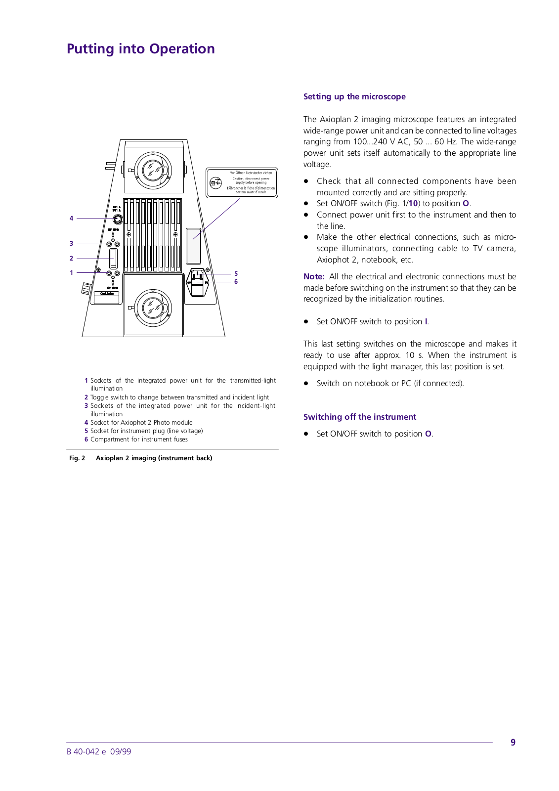
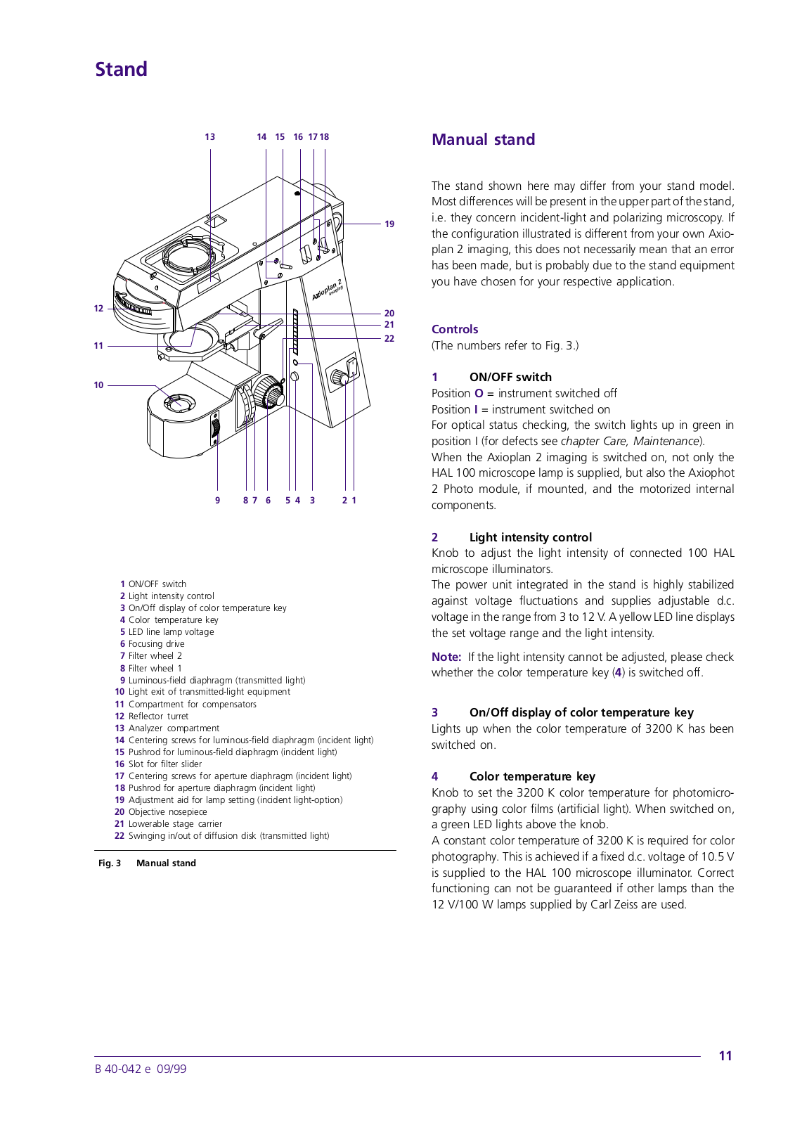
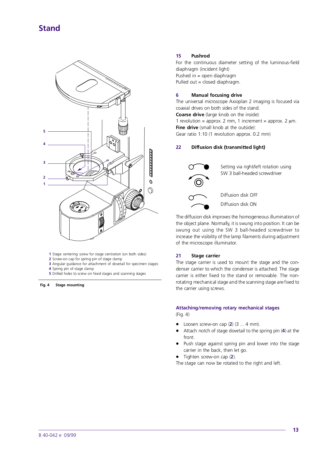
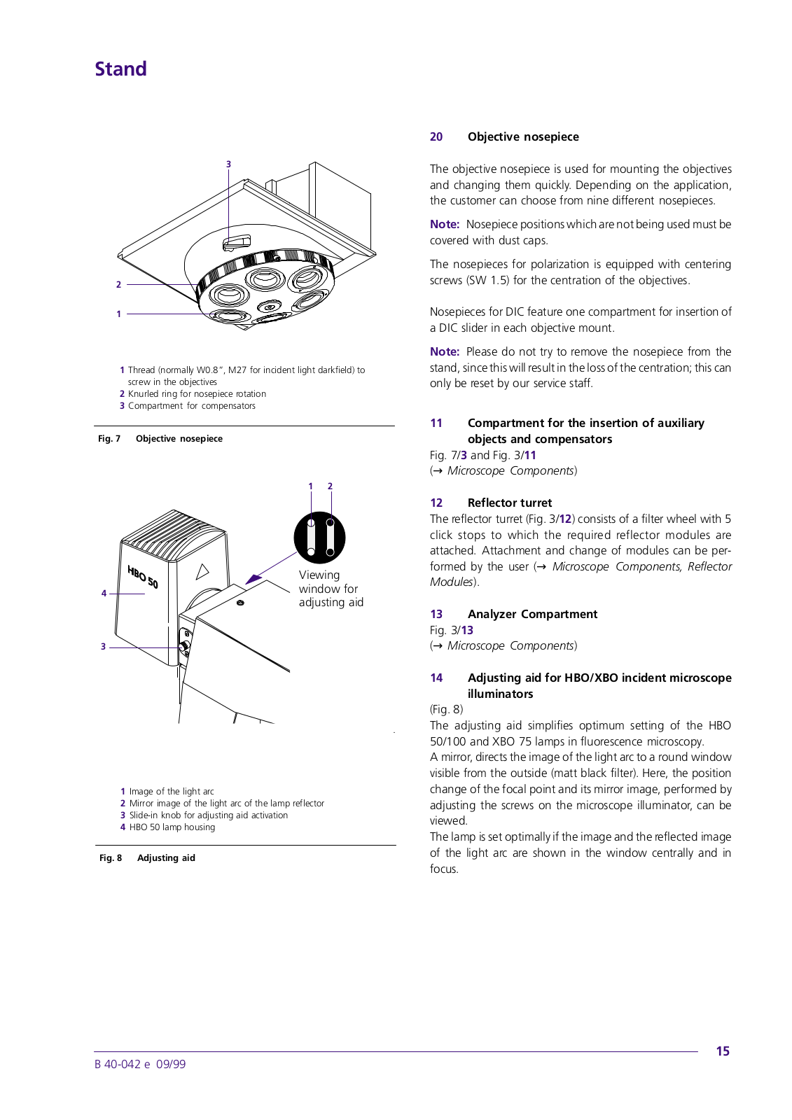
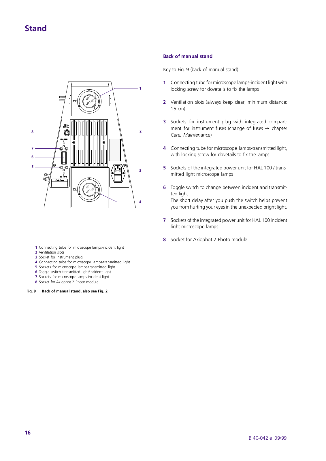
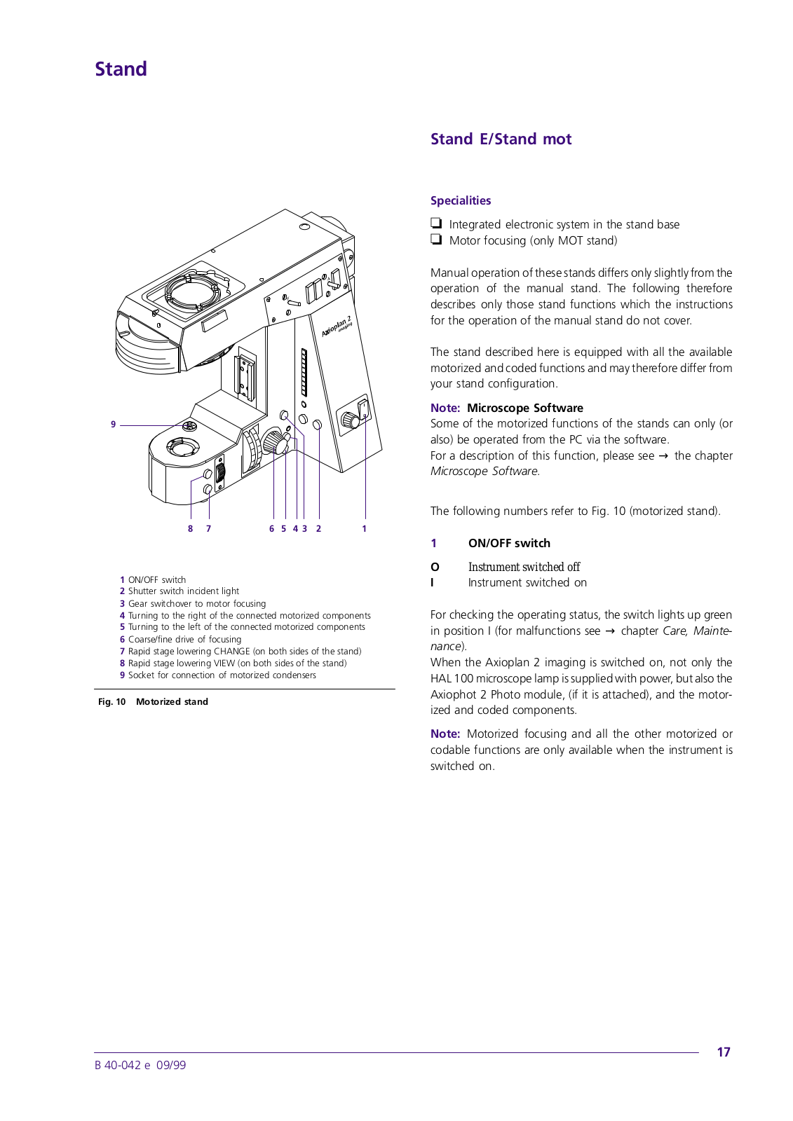
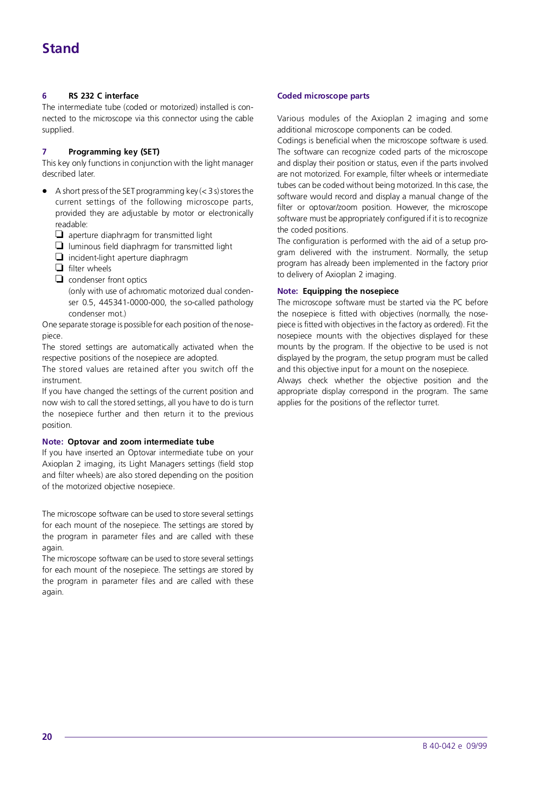
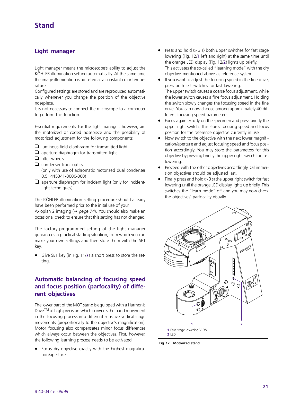
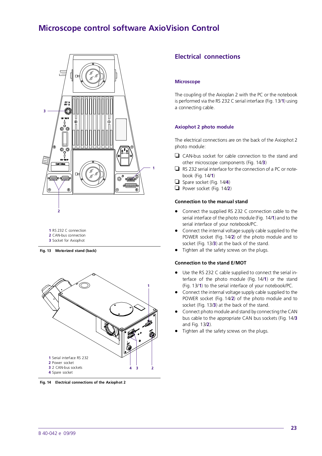
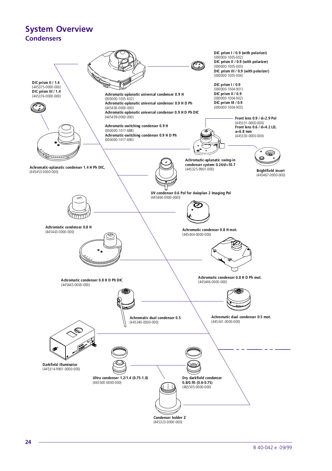
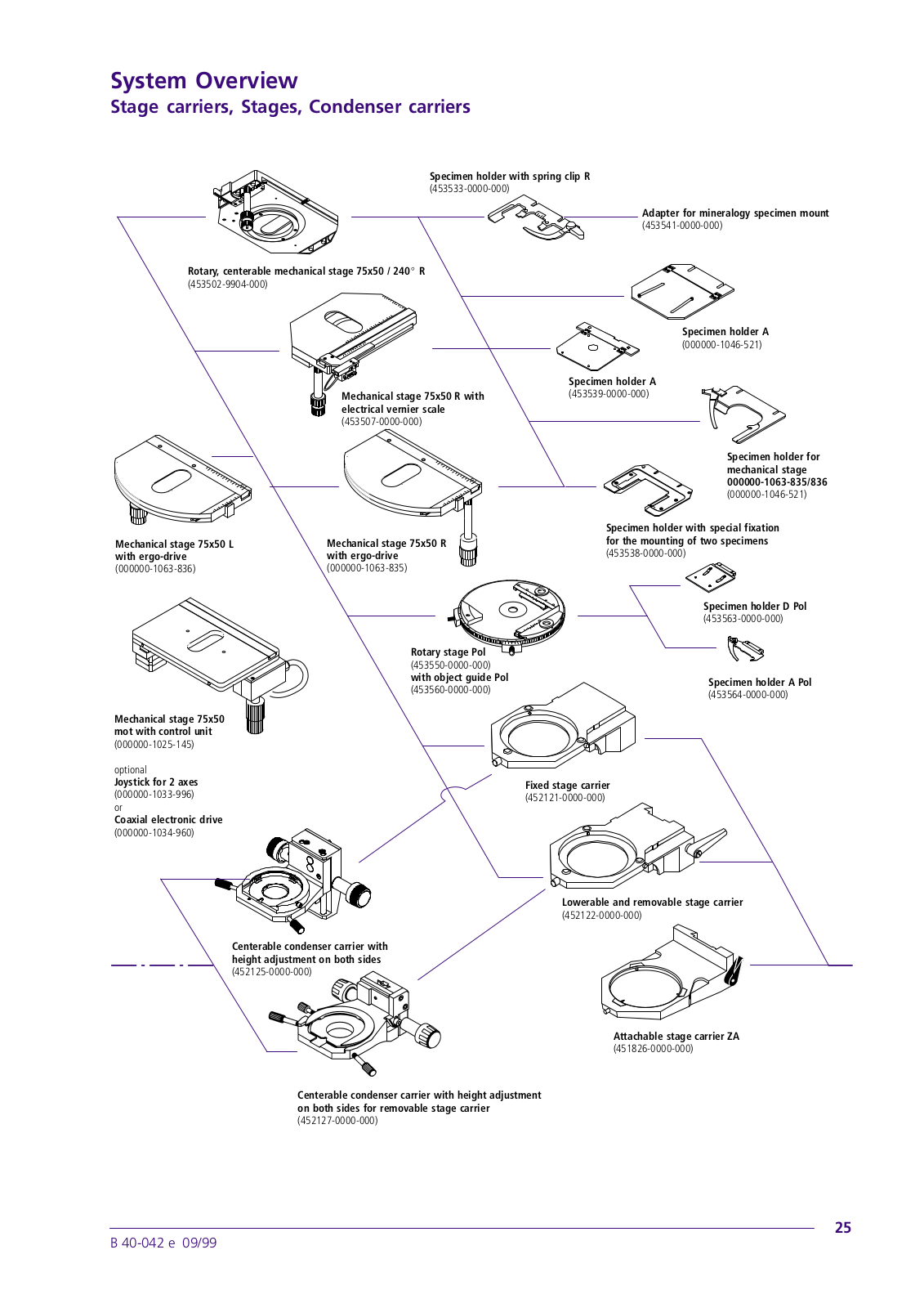
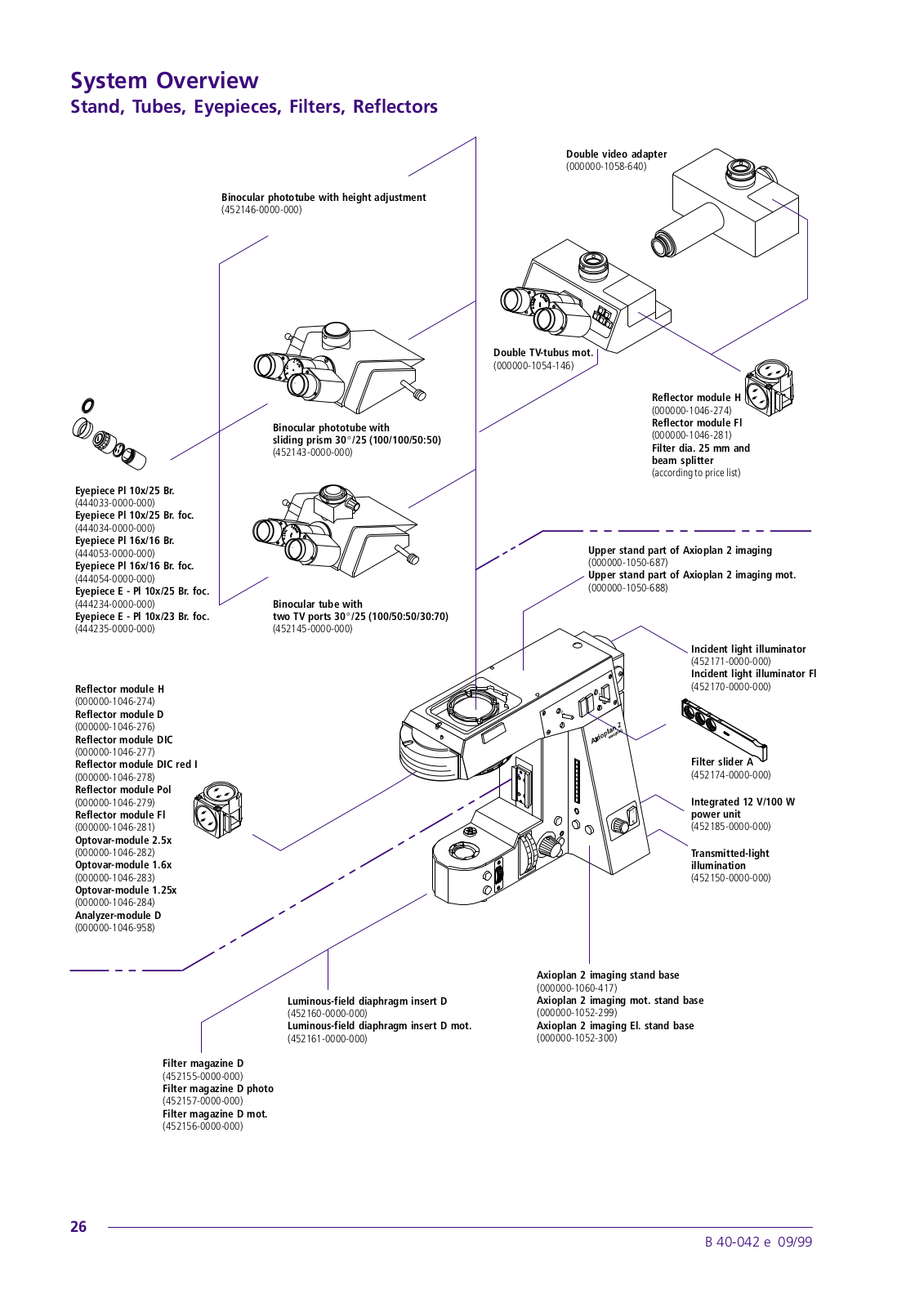
Axiophot 2
Operating Manual
92 pgs
3.68 Mb
0
User Manual
92 pgs
2.3 Mb
0
Table of contents
Loading...
Zeiss Axiophot 2 User Manual
...
Zeiss User Manual
Download
Specifications and Main Features
Frequently Asked Questions
User Manual
Download
Loading...
+
hidden pages
Unhide
You need points to download manuals.
1 point = 1 manual.
You can buy points or you can get point for every manual you upload.
Buy points
Upload your manuals
 Loading...