

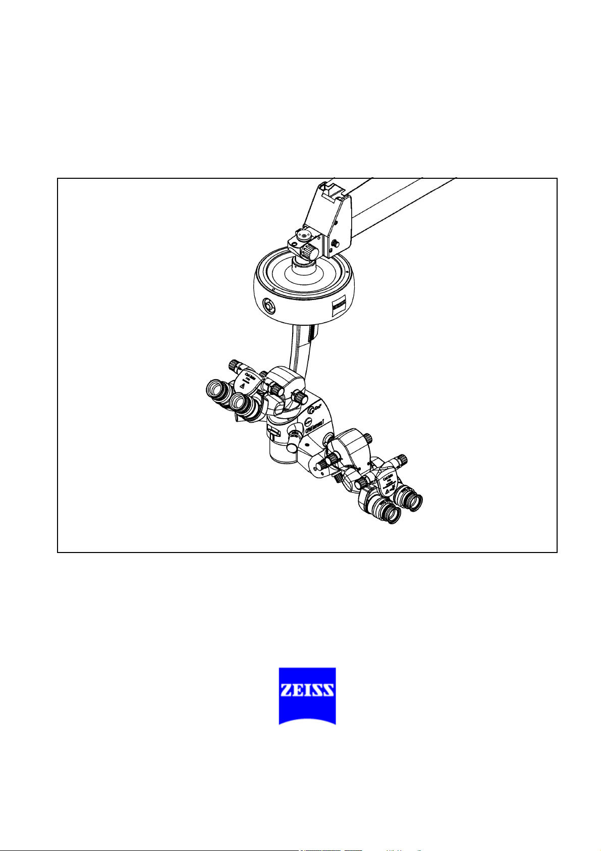
OPMI Lumera® T
with Integrated
Assistant's Microscope
Instructions for use
G-30-1682-en
Issue 4.0
Printed on 02. 02. 2009
2
Key to symbols
Different symbols used in this manual draw your attention to safety aspects and useful tips. These symbols are explained in the following.
Warning!
The warning triangle indicates potential sources of danger which may
constitute a risk of injury for the user or a health hazard.
Caution:
The square indicates situations which may lead to malfunction, defects,
collision or damage of the system.
Note:
The hand indicates hints on the use of the system or other tips for the
user.
®
OPMI
, Lumera®, Superlux®, Invertertube® and HaMode® are regis-
tered trademarks of Carl Zeiss Surgical GmbH.
G-30-1682-en OPMI® Lumera® T Issue 4.0
Printed on 02. 02. 2009

Contents
– Key to symbols 2
Functions at a glance 7
– OPMI Lumera T with integrated assistant's microscope 8
– OPMI Lumera T (option) 9
– Light sources 10
– S88 floor stand 12
– S8 ceiling mount 14
– S81 ceiling mount 16
Safety 19
– Notes on installation and use 21
– When using a wide-angle observation system (e.g. BIOM 3) 25
– Phototoxic retinal injury in eye surgery 25
– Safety devices of the suspension systems 32
– Warning labels and notes 44
Description 51
Lumera T surgical microscope 54
– Intended use 54
– Description of components 54
– Illumination system 60
– Controls, displays, connections 64
– Binocular tubes and eyepieces 72
Light sources 78
– Halogen light source (option) 80
– Superlux Eye light source 84
– Superlux Eye with integrated halogen light source (option) 92
Identical components of the suspension systems 98
– Suspension arm 98
– Display field with control keys 100
G-30-1682-en OPMI® Lumera® T Issue 4.0
Printed on 02. 02. 2009

S88 floor stand 102
– Intended use 102
– Description of components 103
–Design 104
– Stand base with column 106
– Connection panel 108
– Instrument tray (option) 110
– Video monitor (option) 112
S8 ceiling mount 120
– Intended use 120
– Description of components 121
–Design 122
– Power switch with connector (option) 124
S81 ceiling mount 126
– Intended use 126
– Description of components 127
–Design 128
– Power switch, connector and socket (option) 130
OPMI Lumera T with integrated assistant's microscope
on S88 floor stand 132
– Intended use 132
–Design 132
OPMI Lumera T with integrated assistant's microscope
on S8 ceiling mount 134
– Intended use 134
–Design 134
OPMI Lumera T with integrated assistant's microscope
on S81 ceiling mount 136
– Intended use 136
–Design 136
Foot control panel 138
– Intended use 138
–Design 138
G-30-1682-en OPMI® Lumera® T Issue 4.0
Printed on 02. 02. 2009

Preparations 143
Attaching the equipment 144
– Mounting the surgical microscope 144
– Mounting the tube, the eyepieces and the objective lens 148
– Changing the microscope accessories 152
Connections 154
– Connecting the surgical microscope 154
– Connecting the light guide 154
– Strain relief device on S88 floor stand 158
– Connecting the S88 floor stand 160
– Relocating the system 162
Adjusting the supension system 164
– Adjusting the balance setting of the suspension arm 164
– Adjusting the limit of downward movement 166
– Positioning the S8 ceiling mount 168
Settings on the control and display panel 170
– Setting up the suspension system 170
Adjusting the surgical microscope 171
– Optimizing the red reflex 172
– Adjusting the tilt angle 174
Preparing the system for sterile use 176
Operation 179
Checklist 180
– When using a wide-angle observation system (e.g. BIOM 3) 183
Positioning the S88 floor stand 184
Using the display and key field 186
– General functions 186
– Operating the OPMI® on the suspension system 190
Procedure 203
What to do in the event of malfunctions 205
What to do in an emergency 206
– Lamp failure of the halogen light source 206
G-30-1682-en OPMI® Lumera® T Issue 4.0
Printed on 02. 02. 2009

– Lamp failure in the Superlux Eye light source 208
– Failure of lamp control 212
– Failure of the focusing function 212
– Failure of magnetic brakes 214
– Failure of the X-Y coupling 214
– Failure of the zoom function 215
Causes of malfunctions and remedies 216
– Malfunctions in the surgical microscope 216
– Malfunctions in the surgical microscope with integrated
assistant's microscope 218
– Malfunctions in the S8, S81 or S88 suspension system 219
– Malfunctions in the video monitor 221
– Malfunctions in the halogen light source 223
– Malfunctions in Superlux Eye light source 224
Care and maintenance 227
– Care of the unit 228
– Sterilization 229
– Disinfecting the control keys 230
– Changing the halogen lamp 232
– Changing the Superlux Eye xenon lamp module 234
– Balancing the monitor arm 236
System data 239
– Technical data 240
– Magnifications / Fields of view 256
– Ordering data 257
– Spare parts 259
– Disposal 260
– Ambient requirements 261
– CE conformity 261
– Changes to the system 261
Index 263
G-30-1682-en OPMI® Lumera® T Issue 4.0
Printed on 02. 02. 2009

Functions at a glance 7
Functions at a glance
OPMI Lumera T with integrated assistant's microscope 8
OPMI Lumera T (option) 9
Light sources 10
S88 floor stand 12
S8 ceiling mount 14
S81 ceiling mount 16
G-30-1682-en OPMI® Lumera® T Issue 4.0
Printed on 02. 02. 2009

8 Functions at a glance
1
2
3
4
5
6
910 127141311
5
7
34 15 16 178
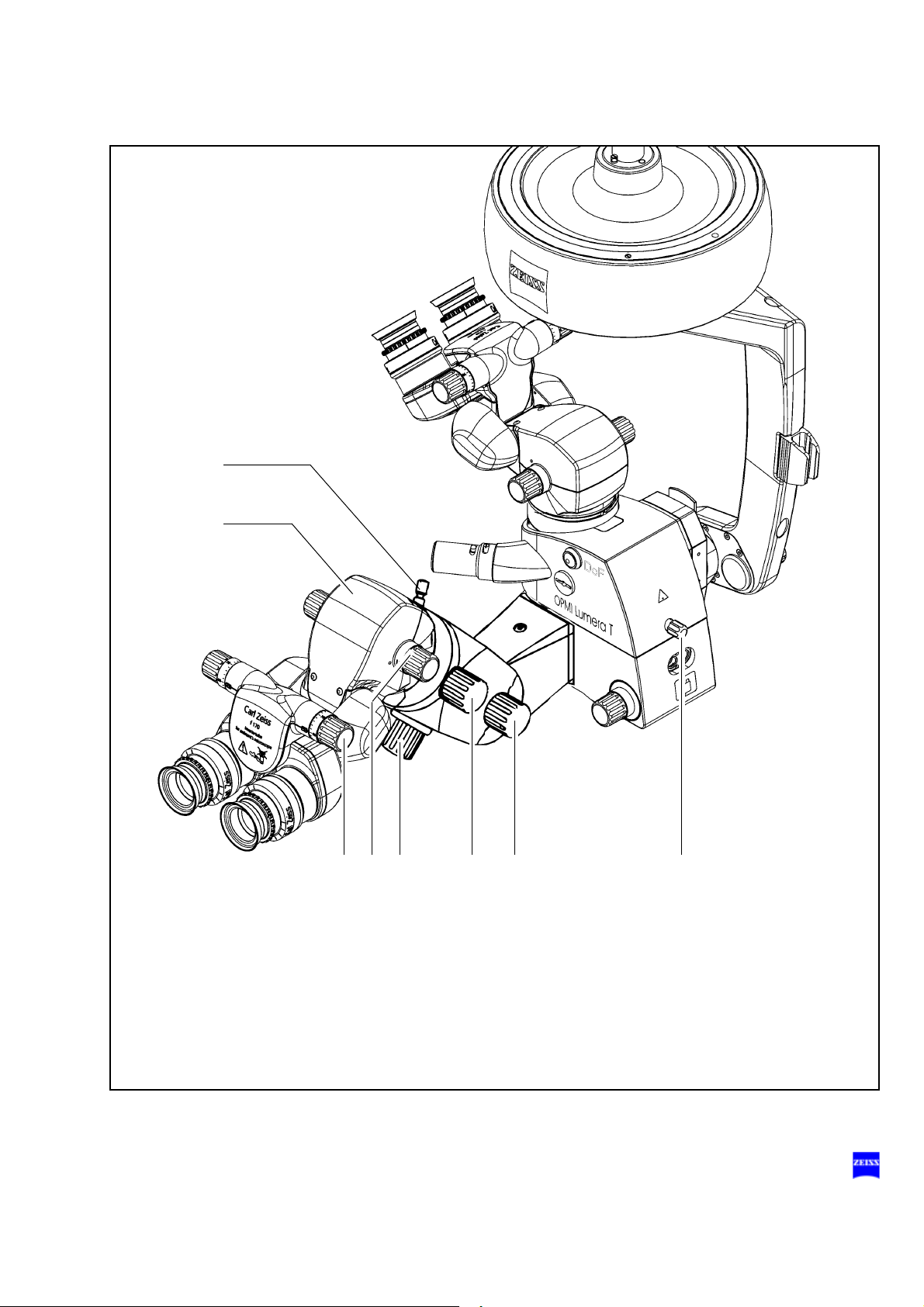
OPMI Lumera T with integrated assistant's microscope
1 Resetting X-Y coupling and focus to their initial positions page 64
2 Adjusting the interpupillary distance page 72
3 Adjusting the eyecups page 76
4 Setting your prescription page 76
5 Unlocking the magnetic brakes page 66
6 Display of the zoom system's magnification factor page 66
7 Changing the magnification of assistant's microscope page 70
8 Setting the inverter function page 70
9 Focusing the assistant's microscope page 70
10 Tilting the surgical microscope page 174
11 Arrows indicating the focusing range page 64
12 Locking screw for assistant's microscope (vertical) page 70
13 Zoom adjustment (manual emergency operation) page 215
14 Adjusting knob for different types of illumination page 68
15 Connecting the light guide page 154
16 Locking screw for assistant's microscope (horizontal) page 174
17 Setting the depth of field (DeepView) page 68
G-30-1682-en OPMI® Lumera® T Issue 4.0
Printed on 02. 02. 2009

Functions at a glance 9
1
2
3
4
5
6
8
10
7
1211
9
5
2
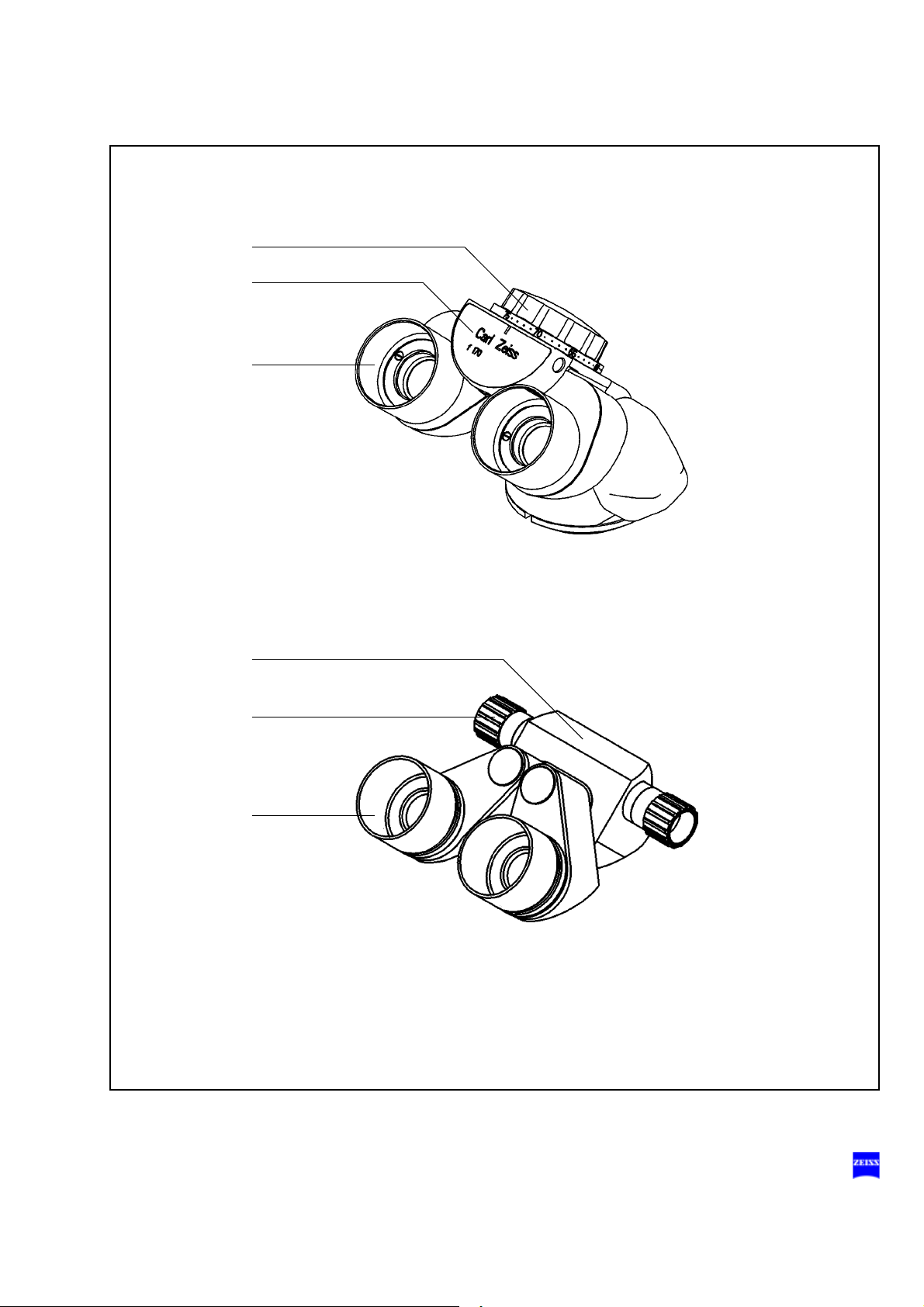
OPMI Lumera T (option)
1 Resetting X-Y coupling and focus to their initial positions page 64
2 Tilting the surgical microscope page 174
3 Adjusting the eyecups page 76
4 Setting your prescription page 76
5 Unlocking the magnetic brakes page 66
6 Display of the zoom system's magnification factor page 66
7 Setting the depth of field (DeepView) page 68
8 Setting the illumination page 62
9 Arrows indicating the focusing range page 64
10 Adjusting the interpupillary distance page 72
11 Zoom adjustment (manual emergency operation) page 215
12 Connecting the light guide page 154
G-30-1682-en OPMI® Lumera® T Issue 4.0
Printed on 02. 02. 2009

10 Functions at a glance
1243
56 8
7
9
Light sources
Halogen light source
1 - Closed flap: main lamp is on
- Open flap: backup lamp is on
2 Selecting a filter page 80
3 Opening the lamp module page 80
4 Manual activation of backup lamp page 80
Superlux Eye light source
5 Selecting a filter page 84
6 Resetting the counter page 88
7 Opening the lamp module page 84
8 Manual activation of backup lamp page 84
9 Red segment is lit - backup lamp is in use page 84
page 80
G-30-1682-en OPMI® Lumera® T Issue 4.0
Printed on 02. 02. 2009

Functions at a glance 11
2456 78 913
Superlux Eye light source with
integrated halogen light source (option)
1 Selecting the filter for Superlux Eye light source page 93
2 Switching manually to the backup lamp of
page 93
Superlux Eye light source
3 Resetting the counter page 38
4 Opening the Superlux Eye lamp module page 80
5 Additional integrated halogen light source:
page 94
- Closed flap: main lamp is on
- Open flap: backup lamp is on
6 Selecting the filter for additional integrated halogen
page 94
light source
7 Opening the lamp module of integrated halogen
page 94
light source
8 Manual activation of the halogen light source's
page 94
backup lamp
9 Superlux Eye light source:
page 94
red segment is lit - backup lamp is in use
G-30-1682-en OPMI® Lumera® T Issue 4.0
Printed on 02. 02. 2009

12 Functions at a glance
S88 floor stand
1 Control unit page 186
2 Light source page 78
3 Unlocking the magnetic brakes of the suspension
system
4 Limiting the suspension arm's downward movement page 166
5 Removing/mounting the coupling for the
surgical microscope
6 Balancing the suspension arm page 164
7 Locking the stand in position page 106
8 Locking the suspension arm in its horizontal position page 98
9 Connecting the foot control panel,
connecting the remote control connector
10 Rated voltage display page 108
11 Connector panel page 108
12 Switching on the suspension system page 108
page 98
page 98
page 108
G-30-1682-en OPMI® Lumera® T Issue 4.0
Printed on 02. 02. 2009
Functions at a glance 13
12 43
56
7 4 8910,11,12
G-30-1682-en OPMI® Lumera® T Issue 4.0
Printed on 02. 02. 2009

14 Functions at a glance
S8 ceiling mount
1 Locking the suspension arm in its horizontal position page 98
2 Unlocking the magnetic brakes of the suspension
system
3 Balancing the suspension arm page 164
4 Light source page 78
5 Control unit (rotatable through 180° or 70°) page 186
6 Connecting the foot control panel,
connecting the remote control connector
7 Switching on the suspension system page 124
8 Releasing - moving - locking the lift arm page 122
9 Removing/mounting the coupling for the
surgical microscope
10 Limiting the suspension arm's downward movement page 166
page 98
page 124
page 98
G-30-1682-en OPMI® Lumera® T Issue 4.0
Printed on 02. 02. 2009

Functions at a glance 15
102798
1
5623 4
G-30-1682-en OPMI® Lumera® T Issue 4.0
Printed on 02. 02. 2009

16 Functions at a glance
S81 ceiling mount
1 Locking the suspension arm in its horizontal position page 98
2 Unlocking the magnetic brakes of the suspension
system
3 Balancing the suspension arm page 164
4 Light source page 78
5 Control unit (rotatable through 180° or 70°) page 186
6 Connecting the foot control panel if the suspension
system is installed on a ceiling track mount (option)
7 Connecting the remote control connector page 130
8 Connecting the foot control panel page 130
9 Switching on the suspension system page 130
10 Removing/mounting the coupling for the
surgical microscope
11 Limiting the suspension arm's downward movement page 166
page 98
page 130
page 98
G-30-1682-en OPMI® Lumera® T Issue 4.0
Printed on 02. 02. 2009

Functions at a glance 17
10 112
9
456123 87
G-30-1682-en OPMI® Lumera® T Issue 4.0
Printed on 02. 02. 2009

18 Functions at a glance
G-30-1682-en OPMI® Lumera® T Issue 4.0
Printed on 02. 02. 2009

Safety
Safety 19
Notes on installation and use 21
When using a wide-angle observation system (e.g. BIOM 3) 25
Phototoxic retinal injury in eye surgery 25
Safety devices of the suspension systems 32
Warning labels and notes 44
G-30-1682-en OPMI® Lumera® T Issue 4.0
Printed on 02. 02. 2009

20 Safety
The device described in this manual has been designed and tested in accordance with Carl Zeiss safety standards as well as German and international standards. This guarantees a high degree of instrument safety.
The system described in this user manual has been designed in compliance with the requirements of:
–EN –IEC –UL –CSA
In accordance with Directive 93/42/EEC for medical devices, the complete quality management system of the company Carl Zeiss Surgical
GmbH, 73446 Oberkochen, Germany, has been certified by DQS Deutsche Gesellschaft zur Zertifizierung von Managementsystemen GmbH, a
notified body, under registration number 250758 MP23.
– As per Directive 93/42/EEC, the unit is a Class I instrument.
– For USA: FDA classification Class I.
We would like to provide you with information about safety aspects which
must be observed when handling this device. This chapter contains a
summary of the most important information concerning matters relevant
to instrument safety.
Important safety information has been incorporated in this manual and is
marked with a warning triangle accordingly. Please give this information
your special attention.
The correct use of the system is absolutely vital for safe operation. Please
make yourself totally familiar with the contents of this manual prior to startup of the instrument. Please also observe the user manuals of any additional equipment. Further information is available from our service department or from authorized representatives.
• Please observe all applicable accident prevention regulations.
• The instrument must be connected to a special emergency backup
line supply in accordance with the regulations or directives which apply in your country.
G-30-1682-en OPMI® Lumera® T Issue 4.0
Printed on 02. 02. 2009

Safety 21
Notes on installation and use
Safe working order
• Do not operate the equipment contained in the delivery package in
– explosion-risk areas,
– the presence of inflammable anesthetics or volatile solvents such
as alcohol, benzine or similar chemicals.
• Do not station or use the instrument in damp rooms. Do not expose
the instrument to water splashes, dripping water or sprayed water.
• Switch off the unit at the power switch if you notice any smoke, sparks
or unusual noise. Do not use the unit until it has been repaired by our
service team.
• Do not place any fluid-filled containers on top of the instrument. Make
sure that no fluids can seep into the instrument.
• Do not force cable connections. If the male and female parts do not
readily connect, make sure that they are appropriate for one another.
If any of the connectors are damaged, have our service representative
repair them.
• Potential equalization: If requested, the instrument can be incorporated into potential equalization measures.
• Do not use a mobile phone in the vicinity of the equipment because
the radio interference can cause the equipment to malfunction. The effects of radio interference on medical equipment depend on a number
of various factors and are therefore entirely unforeseeable.
• Modifications and repairs on these instruments or instruments used
with them may only be performed by our service representative or by
other authorized persons.
• The manufacturer will not accept any liability for damage caused by
unauthorized persons tampering with the instrument; this will also forfeit any rights to claim under warranty.
• Over longer distances (e.g. removal, return for repair, etc), the instrument may only be transported in the original packaging or in special
return packaging. Please contact your dealer or the Carl Zeiss service
team.
• Use this instrument only for the applications described.
G-30-1682-en OPMI® Lumera® T Issue 4.0
Printed on 02. 02. 2009

22 Safety
• Only use the instrument with the accessories supplied. Should you
wish to use other accessory equipment, make sure that Carl Zeiss or
the equipment manufacturer has certified that its use will not impair
the safety of instrument.
• When mounting accessory equipment, please make sure that the admissible total weight of the surgical microscope is not exceeded. (See
label or chapter "Technical data").
• Only personnel who have undergone training and instruction are allowed to use this instrument. It is the responsibility of the customer or
institution operating the equipment to train and instruct all staff using
the equipment.
• Keep the user's manuals where they are easily accessible at all times
for the persons operating the instrument.
• Never look at the sun through the binocular tube, the objective lens or
an eyepiece.
• Do not pull at the light guide cable, at the power cord or at other cable
connections.
This system is a high-grade technological product. To ensure optimum
performance and safe working order, we recommend having it checked
by our service representative as part of regular scheduled maintenance.
If a failure occurs which you cannot correct with the aid of the chapter
"What to do in the event of malfunctions“, attach a sign to the system
stating it is out of order and contact our service representative.
• Observe the labels showing the symbol "Risk of crushing“!
Notes on EMC (electromagnetic compatibility)
The system meets the EMC requirements of IEC 60601-1-2. During use
of the system, the precautionary measures concerning EMC listed below
must be observed.
Only use accessories that have been approved by Carl Zeiss for this
system.
Do not use any portable or mobile high frequency communication devices
in the vicinity of the system, as this may lead to an impairment of its function.
The system complies with the limits for a Class A device concerning radio
frequency emission. However, the possibility of interference to high frequency receiving devices (e.g. TV sets or radios) being used in the surroundings cannot be ruled out. If interference of this type occurs, please
inform your Carl Zeiss Service.
G-30-1682-en OPMI® Lumera® T Issue 4.0
Printed on 02. 02. 2009

Safety 23
Requirements for operation
• For ceiling mounts only: Our service staff or a qualified person appointed by us will install the system on ceiling anchors which have
been properly mounted by the construction engineers responsible.
These ceiling anchors must comply with the specifications contained
in our planning manual.
• Our service representative or an expert authorized by us will install the
system. Please ensure that the following requirements are met for further operation:
– All mechanical connections (details in the user's manual) which are
relevant to safety are properly connected and screw connections tightened.
– All cables and plugs are in good working condition.
– The voltage setting on the instrument conforms to the rated voltage of
the line supply on site.
– The instrument is plugged into a power outlet which has a properly
connected protective ground contact.
– The power cord being used is the one designed for use with this in-
strument.
Before every use and after re-equipping the instrument
• Make sure that all ”Requirements for operation” are fulfilled.
• Go through the checklist.
• Re-attach or close any covers, panels or caps which have been removed or opened.
• Pay special attention to warning symbols on the instrument (triangular
warning signs with exclamation marks), labels and any parts such as
screws or surfaces painted red.
• Do not cover any ventilation openings.
For every use of the instrument
General
• Never operate the system unattended.
• Excessive radiation exposure times may lead to retinal injury in the patient's eye. Never leave a system unattended when the light source
has been activated.
G-30-1682-en OPMI® Lumera® T Issue 4.0
Printed on 02. 02. 2009

24 Safety
• Avoid looking directly into the light source, e.g. into the microscope objective lens or a light guide.
• When the illumination is on, the light guide must be connected at both
ends. Otherwise there is a risk of fire or burn injuries.
• Make sure that the instrument has been switched off before you
change the xenon lamp module. When switched on, the ignition system generates high voltage.
Xenon lamps feature high luminance and a spectrum resembling that of
natural daylight. Therefore, only special xenon lamps approved by Carl
Zeiss must be used in ophthalmology.
• Any kind of radiation has a detrimental effect on biological tissue.This
also applies to the light illuminating the surgical field. Please therefore
reduce the brightness and duration of illumination on the surgical field
to the absolute minimum required.
• Phototoxic effect of light beams. When operating on the eye, always
use the yellow protection filter to ensure that the patient's eye is not
exposed to unnecessary (blue) radiation (risk of retinal injury).
• Adjust the illumination intensity as required for the type of illumination
used and the radiation exposure time. You will find the values recommended by Carl Zeiss in the table "Maximum radiation exposure
times" on page 29.
S88 floor stand
• Using the locking pedal on the base, secure the stand in position.
Make sure that the stand is stable and cannot roll away.
After every use of the instrument
• Always use the main power switch of the instrument to turn it off.
• The main power switch must always be turned off when the instrument
is not in use.
G-30-1682-en OPMI® Lumera® T Issue 4.0
Printed on 02. 02. 2009

Safety 25
1
2
Risk of collision!
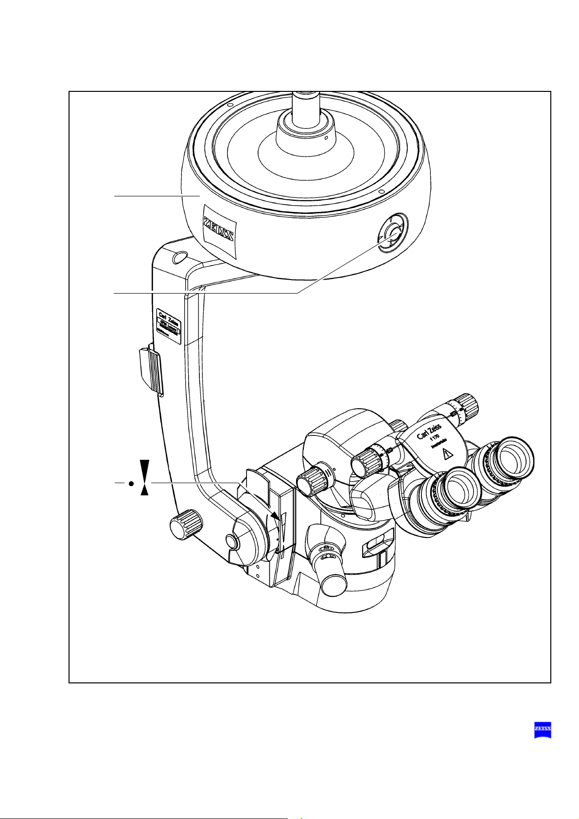
When using a wide-angle observation system (e.g. BIOM 3)
When using a wide-angle observation system (e.g. BIOM 3 from Oculus)
which is usually installed between the surgical microscope and the patient, make sure that the patient is neither put at risk nor injured by the motorized focusing system or the movement of the suspension system arm.
Only use accessories expressly certified by the manufacturer for combination with the surgical microscopes described in this manual.
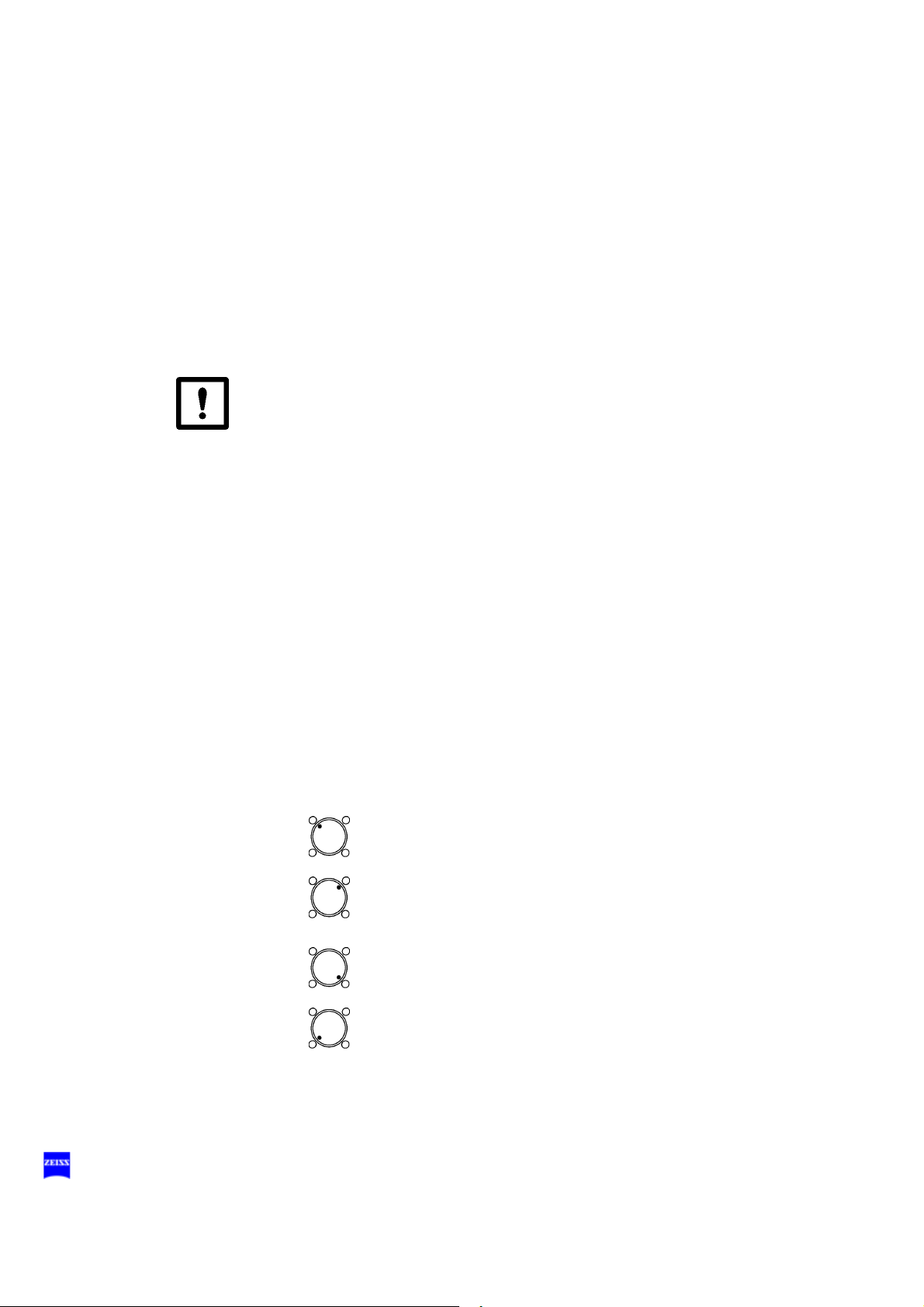
Warning!
• With the wide-angle observation system swung out of position, always
position the microscope body in such a way that index dot (1) of the
microscope's focus is in the middle of triangle (2) of the marking.
• Select a medium magnification (e.g. 1.0).
• Lower the surgical microscope toward the surgical field until you see
the patient's cornea sharply defined.
• Turn the setting screw for limiting the downward movement clockwise
as far as it will go and check without the patient that the suspension
arm cannot be lowered any further.
It is vital that you read the user manual for the wide-angle observation
system used (e.g. BIOM 3 from Oculus).
Phototoxic retinal injury in eye surgery
General
1)-5)
Several papers
surgery have been published. A comprehensive review of these publications reveals five aspects of particular concern:
– Illumination characteristics (spectral composition)
– Illumination intensity
dealing with the problem of phototoxicity in ophthalmic
G-30-1682-en OPMI® Lumera® T Issue 4.0
– Angle of illumination
– Focus of the light source
– Exposure time to light
Printed on 02. 02. 2009

26 Safety
In the following, comments on these aspects are given and a description
of how Carl Zeiss, as a manufacturer, makes allowance for them in its
systems.
Illumination characteristics (spectral composition)
Studies on the exposure of the eye to light of varying spectral composition
date back to the early 1950s. These studies suggest that the potential
hazard of phototoxic injury to the patient's retina can be reduced by
blocking out the blue and ultraviolet light below a wavelength of 475 nm.
For protection of the retina, Carl Zeiss offers the blue barrier filter (retina
protection filter) as a standard feature of the OPMI Lumera surgical microscopes. This reduces not only the exposure of the patient's eye to light,
but also that of the surgeon's.
An important point to note here, however, is that the use of filters will inevitably change the perceived color of the light. For this reason, the physician may initially have to get used to the changed appearance of the anatomical structures.
Illumination intensity
The majority of researchers suggest that the surgeon should use the
lowest light intensity required at the patient's eye to guarantee good
viewing during surgery.
Carl Zeiss has addressed this aspect by providing its systems with a device for continuously varying the brightness of the light source. This permits the surgeon to optimally adapt the light intensity at the patient's eye
to the conditions existing in each case.
Angle of illumination
1)-4)
A number of publications
suggest that the microscope should be
tilted to reduce the exposure of the macula to direct illumination.
Carl Zeiss ophthalmic surgical microscopes are therefore equipped with
the following:
– Tilting mechanism for the microscope body
– Surrounding field illumination with brightness control
– Red reflex illumination (stereo coaxial illumination)
G-30-1682-en OPMI® Lumera® T Issue 4.0
Printed on 02. 02. 2009

Safety 27
Focus of the light source
Studies show that injuries are likely to occur if the filament of the light
source is imaged on the patient's retina. The peak intensity of a filament
is considerably higher than that of an even and extended light source
such as a light guide.
This is the reason why Carl Zeiss uses fiber optic illumination in its surgical microscope systems.
Exposure time to light
According to some publications, the phakic and aphakic eye should not
be exposed to the light source longer than a few minutes. In all surgical
cases, the retinal exposure time depends on the type and duration of the
procedure and possible case complications. It is therefore recommended
in ophthalmic surgery to keep the light intensity as low as possible, or to
use a device which prevents the light from entering through the patient's
pupil. It is also recommended to make sure that the patient's eye is not
additionally exposed to the light of surrounding light sources. This
problem has been solved by Carl Zeiss by the use of a retinal protection
device that can be swung into the microscope's illumination beam path
and a blue barrier filter (retina protection filter).
Brightness control
The brightness control scale of our systems has a linear structure with
values ranging from 0.5 to 10. The stipulations of standard ISO/FDIS
15004-2:2006(E) result in maximum radiation exposure times for the different illumination configurations as specified in the table "Maximum radiation exposure times".
The microscope light source - like any bright light source - may present a
hazard to the patient's eye both in the form of immediately visible thermal
damage to the retina as well as phototoxic chemical reactions which may
lead to photoretinitis. The factors which play an important role in determining the phototoxic risk are:
– Lamp brightness.
– Spectral distribution of the light (UV and blue are more dangerous
than longer wavelengths).
– Duration of direct exposure.
– Pupil size.
– Clarity of ocular media (infants and young children, for example,
may be at a higher risk).
G-30-1682-en OPMI® Lumera® T Issue 4.0
Printed on 02. 02. 2009

28 Safety
– Phakic status of the eye (aphakic and pseudo-aphakic eyes with-
– Previous exposure to bright light such as retinal photography, es-
The following table is intended to provide the surgeon with a guideline in
determining the potential hazard. The data has been calculated for a
worst-case scenario of direct, uninterrupted exposure of an aphakic eye
with an 8 mm dilated pupil. The calculations are based on the recommended occupational health daily exposure limits as defined in
safety factor of 10 has been used in determining these limits.
During cataract procedures, factors such as lenticular material, instruments such as the phaco handpiece, and movement of the eye provide
interruption of the exposure and would be expected to significantly
lengthen the time before photoretinitis might be expected to occur.
A prospective study
gery did not reveal any phototoxic retinal injuries for procedure times of
up to 30 minutes if the calculated maximum recommended exposure time
was 150 seconds. However, it was also found that at the same brightness
setting, phototoxic retinal injury could be expected after approximately
100 min.
out UV and blue filtering IOLs are at a higher risk).
pecially within the last 24 hrs.
7)
of the effects of microscope illumination during sur-
6)
. A
The red reflex illumination (stereo coaxial illumination) of OPMI Lumera
has been designed to provide a bright red reflex using only very small
quantities of light at the center of the light spot. The peripheral field illumination causes higher exposure of the retina, but usually not directly of the
macula, depending on the position of the eye. For cataract procedures,
we recommend adjusting the surrounding field illumination to be somewhat darker than the central red reflex spot. Not only does this setting
minimize phototoxic risk, but it also reduces glare from the patient's
sclera.
Other recommendations for minimizing phototoxic risk are:
• Always use the lowest possible brightness setting.
• Use the blue barrier filter (retina protection filter) to block the blue
spectrum of light. The blue barrier filter will increase the recommended
exposure times by factor three.
• When working on the exterior eye, use the retinal protection device to
prevent light from entering the pupil, especially when the pupil is dilated.
• Turn off the microscope illumination system or cover the patient's eye
during pauses in surgery.
G-30-1682-en OPMI® Lumera® T Issue 4.0
Printed on 02. 02. 2009

Safety 29
Maximum radiation exposure times
The use of the blue barrier filter (retina protection filter) increases the recommended exposure time by a factor of 3 compared with the values specified below.
Red reflex illumination (stereo coaxial illumination)
Scale display
of Illumination
Max. exposure time in minutes
Halogen Xenon Xenon with
HaMode filter
2.5 50 8.2 28
5 21 4.2 16.5
7.5 13 2.9 10.3
10 9 2.2 8.5
Surrounding field illumination
Scale display
of Illumination
Max. exposure time in minutes
Halogen Xenon Xenon with
HaMode filter
2.58.72.58.9
53.71.35.2
7.52.20.93.3
10 1.6 0.7 2.7
Note:
The illumination system of the surgical microscope contains a UV
blocking filter as a standard feature.
This helps the surgeon to reduce the risk of phototoxic retinal injury in the
patient.
List of references
1)
H. Stiller, and B. Rassow, "Light hazards to the patient's retina from
ophthalmic instruments," Applied Optics-OT 30, 2187-2196 (1991).
2)
American Conference of Governmental Industrial Hygienists, "Documentation of the Threshold Limit Values for physical agents. 7th Edition,"
(American Conference of Governmental Industrial Hygienists, Cincinnati,
2001).
3)
S. G. Khwarg, F. A. Linstone, S. A. Daniels, S. J. Isenberg, T. A.
Hanscom, M. Geoghegan, and B. R. Straatsma, "Incidence, risk factors,
and morphology in operating microscope light retinopathy," Am. J. Ophthalmol. 103, 255-263 (1987).
G-30-1682-en OPMI® Lumera® T Issue 4.0
Printed on 02. 02. 2009

30 Safety
4)
G. Kleinmann, P. Hoffman, E. Schechtman, and A. Pollack, "Microscope-induced retinal phototoxicity in cataract surgery of short duration,"
Ophthalmology 109, 334-338 (2002).
5)
ISO/FDIS 15004-2:2006(E) Optical instruments -- Fundamental requirements and test methods -- Part 2: Light hazard protection
6)
David Sliney, Danielle Aron-Rosa, Francois DeLori, Franz Fankhauser,
Robert Landry, Martin Mainster, John Marshall, Bernard Rassow, Bruce
Stuck, Stephen Trokel, Teresa Motz West, and Michael Wolffe, Adjustment of guidelines for exposure of the eye to optical radiation from ocular
instruments: statement from a task group of the International Commission
on Non-Ionizing Radiation Protection (ICNIRP) APPLIED OPTICS Vol.
44, No. 11, p 2162 (10 April 2005)
7)
Byrnes, G.A., Antoszyk, A.N., Mazur, D.O., Kao, T.C., Miller, S.A.,
Photic maculopathy after extracapsular cataract surgery. A prospective
study, 1992/05/01 Ophthalmology, VL - 99, IS - 5, SP - 731, EP - 737,
PB - Elsevier
G-30-1682-en OPMI® Lumera® T Issue 4.0
Printed on 02. 02. 2009

Safety 31
G-30-1682-en OPMI® Lumera® T Issue 4.0
Printed on 02. 02. 2009

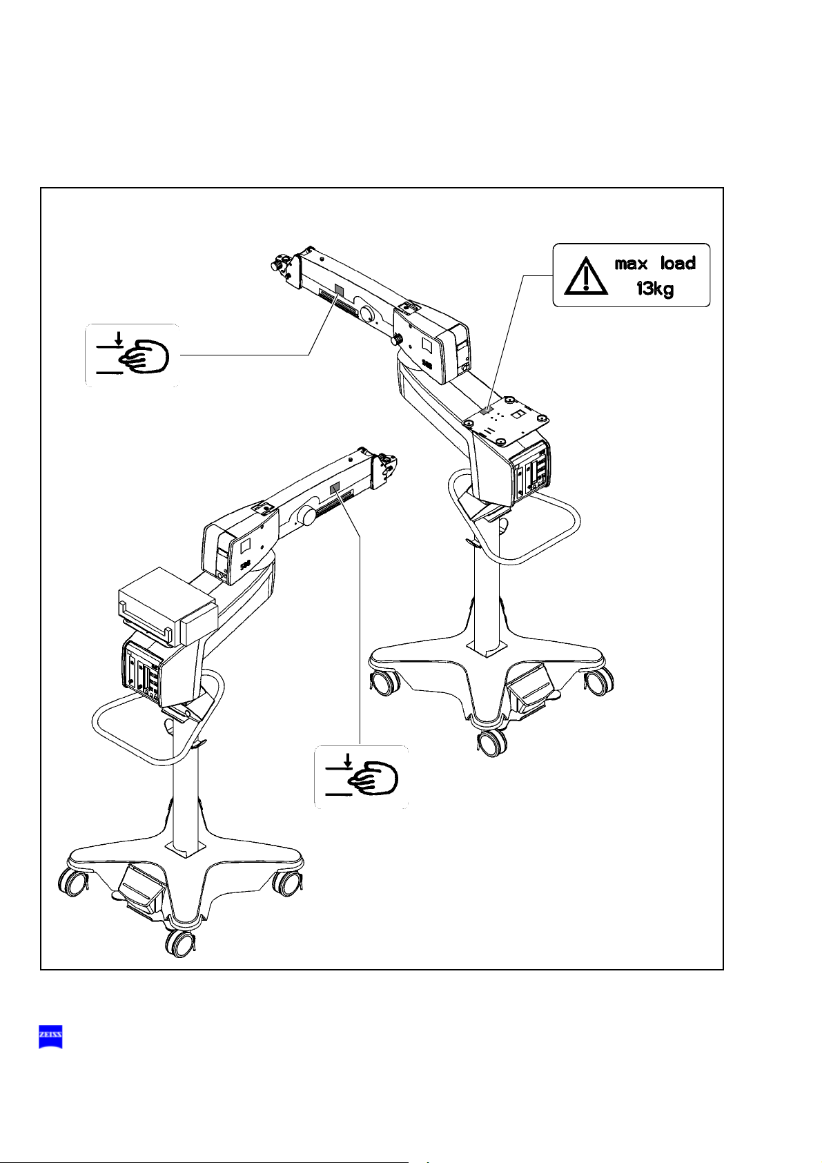
32 Safety
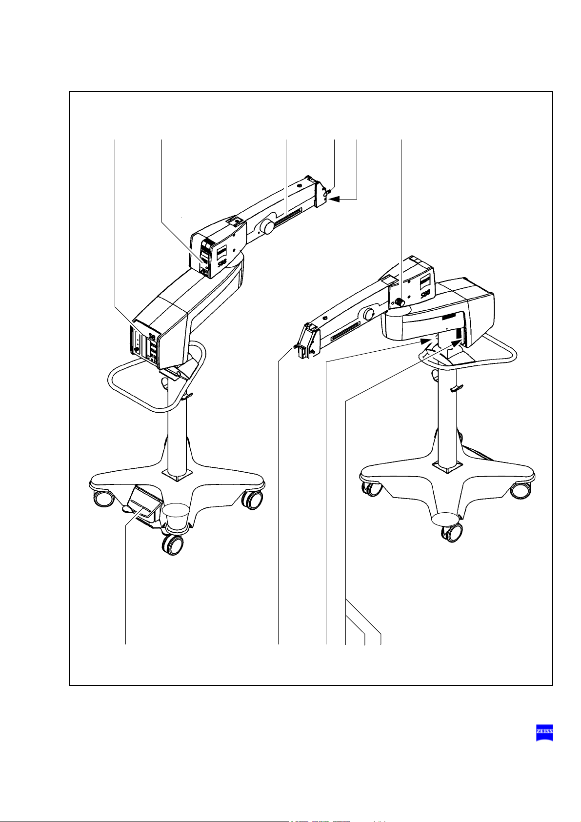
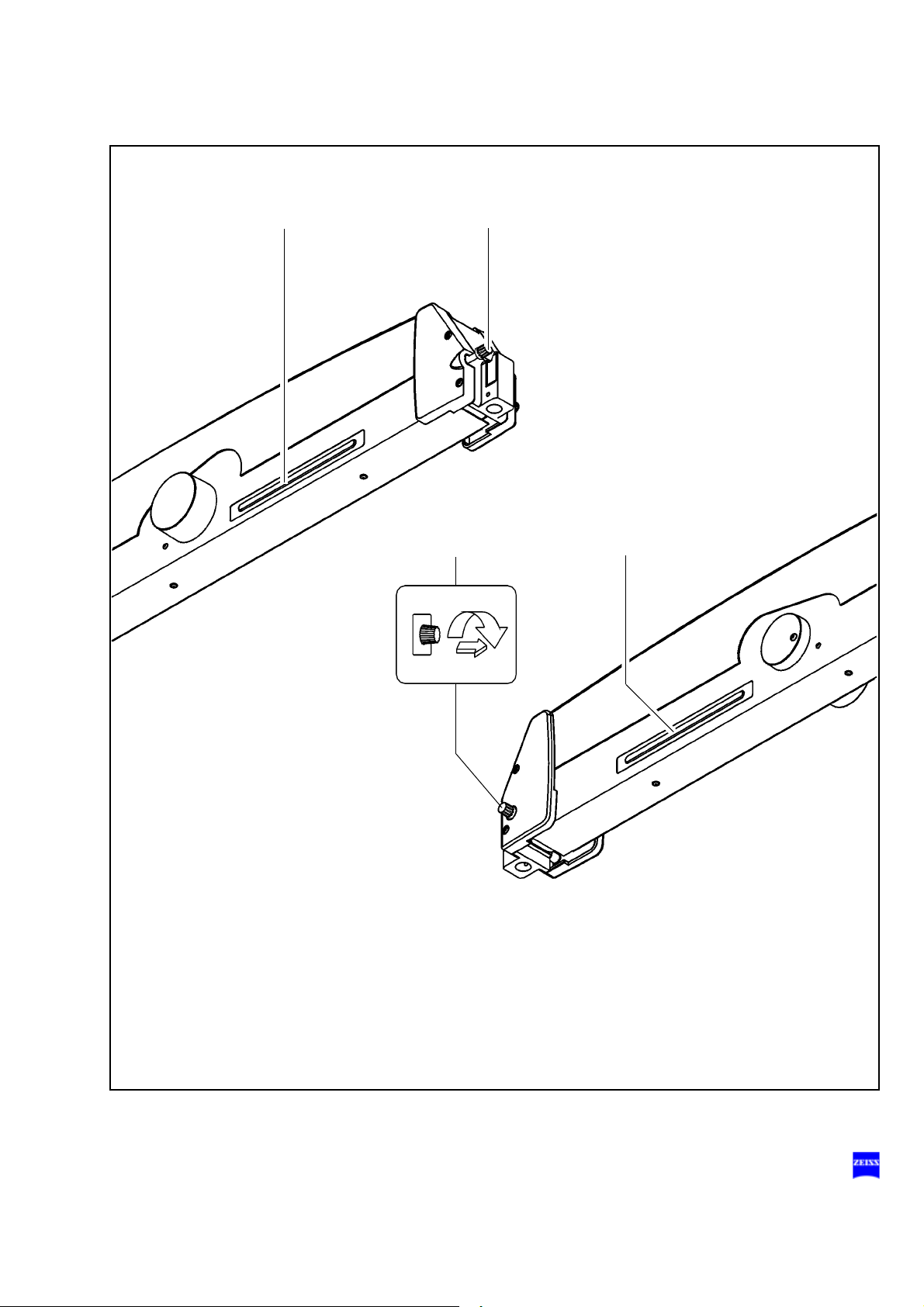
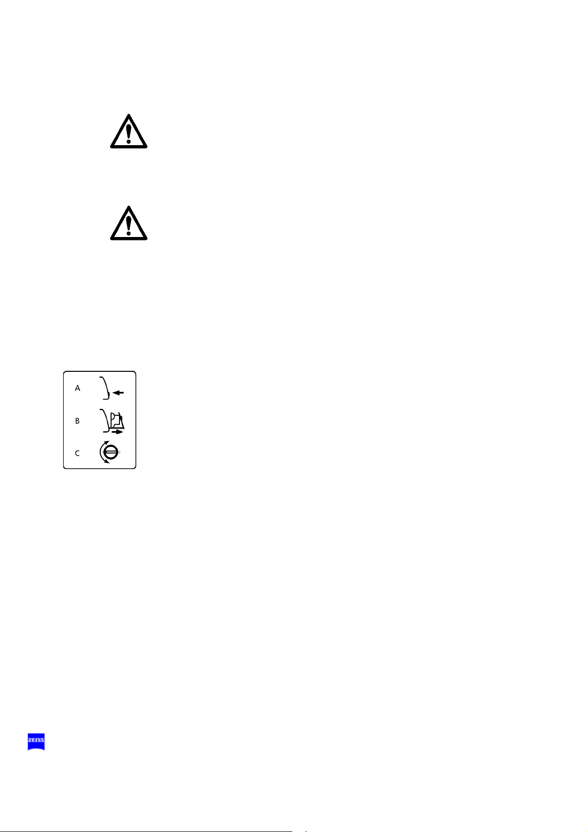
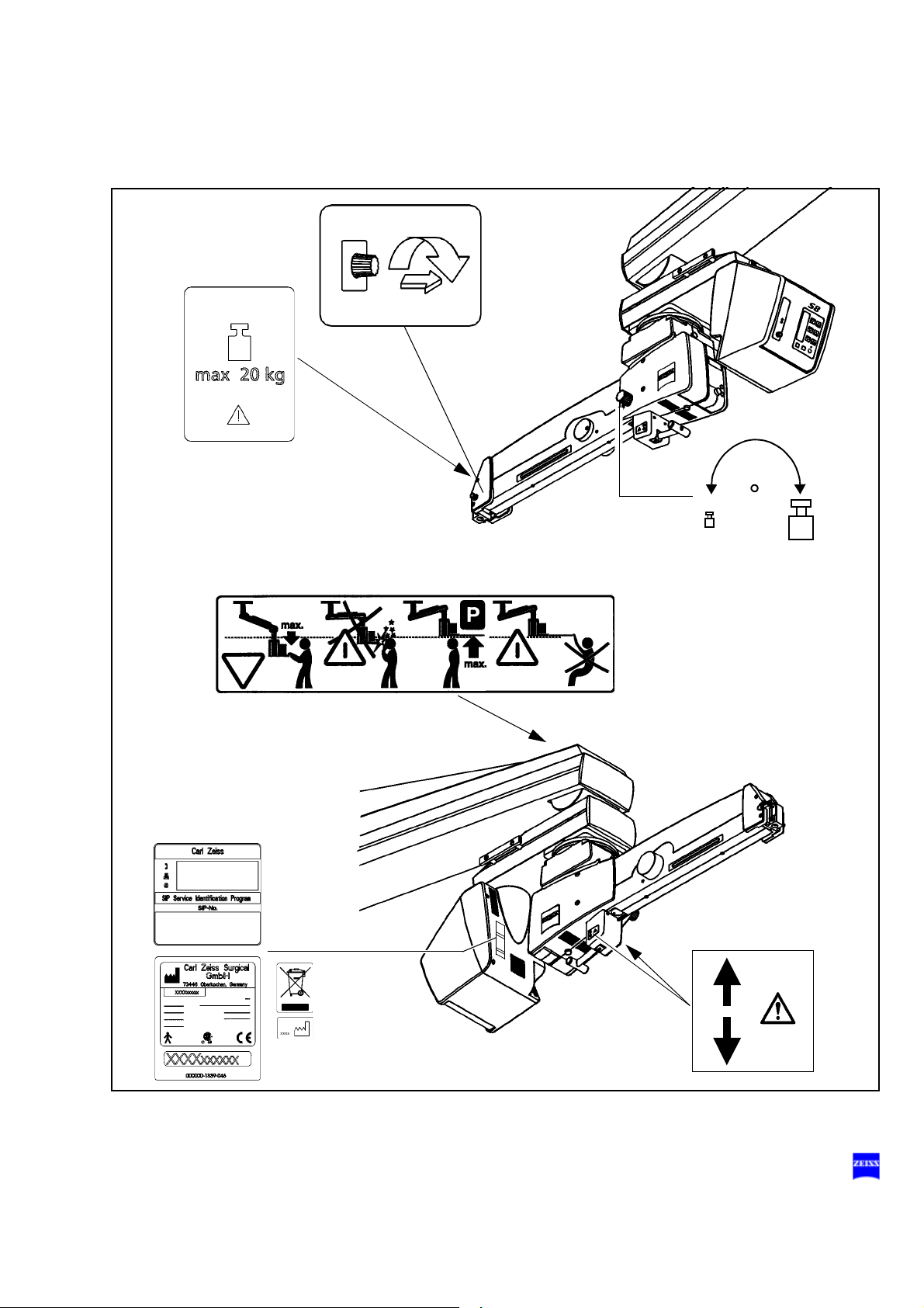
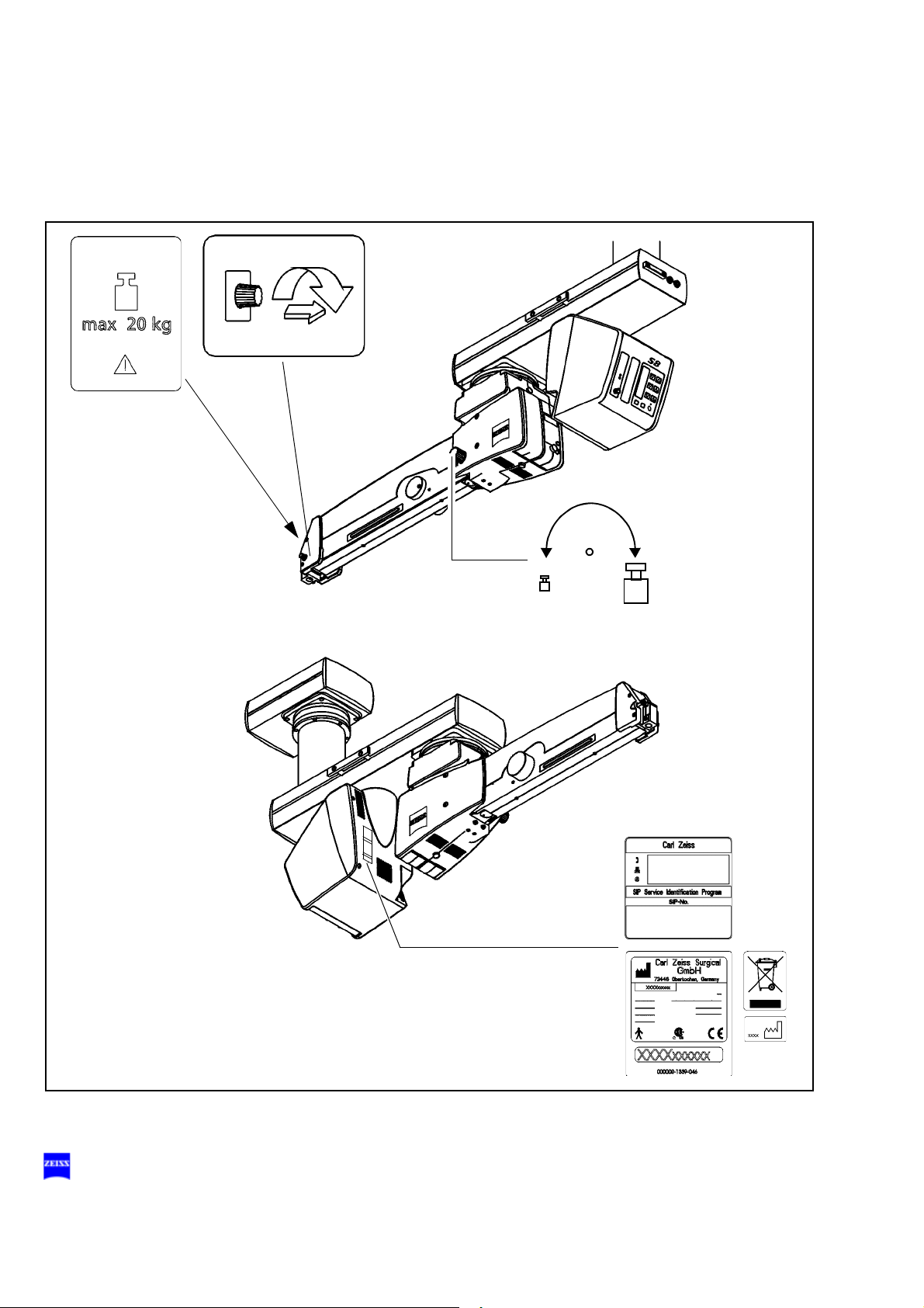
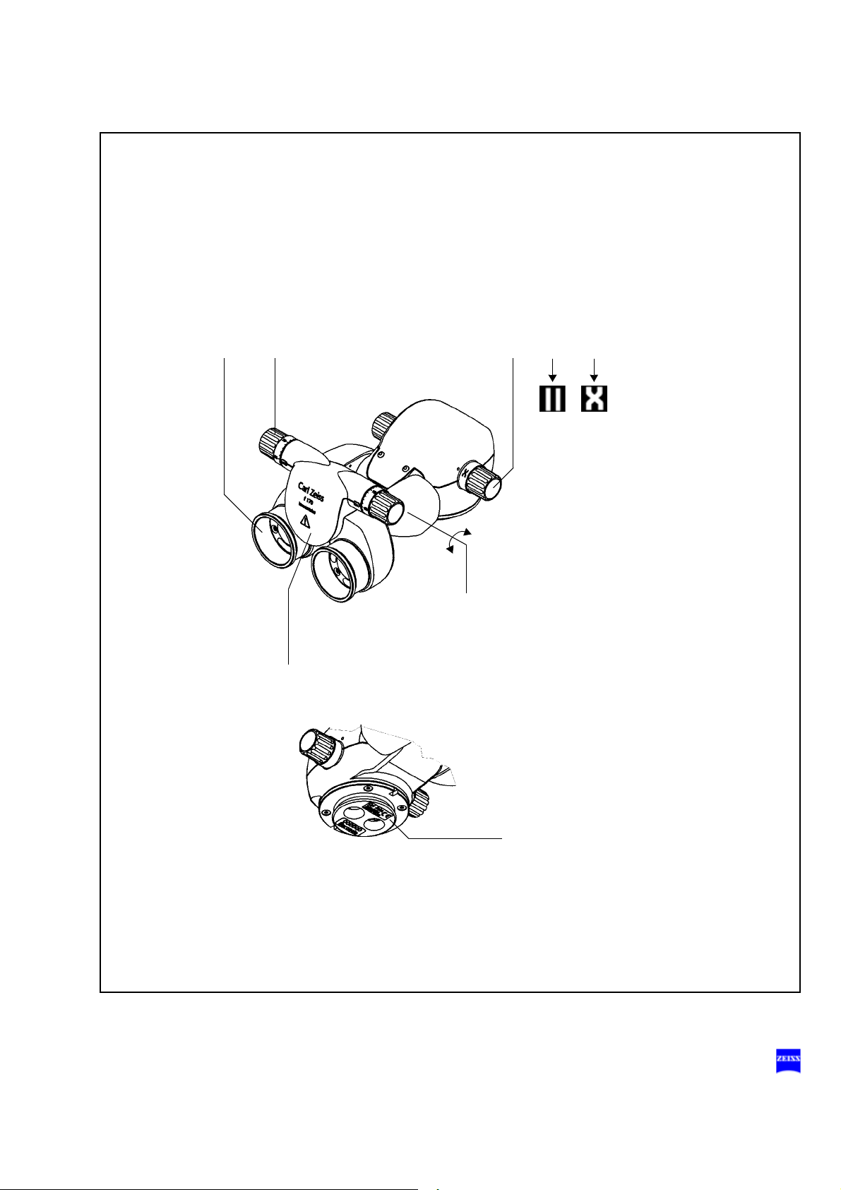
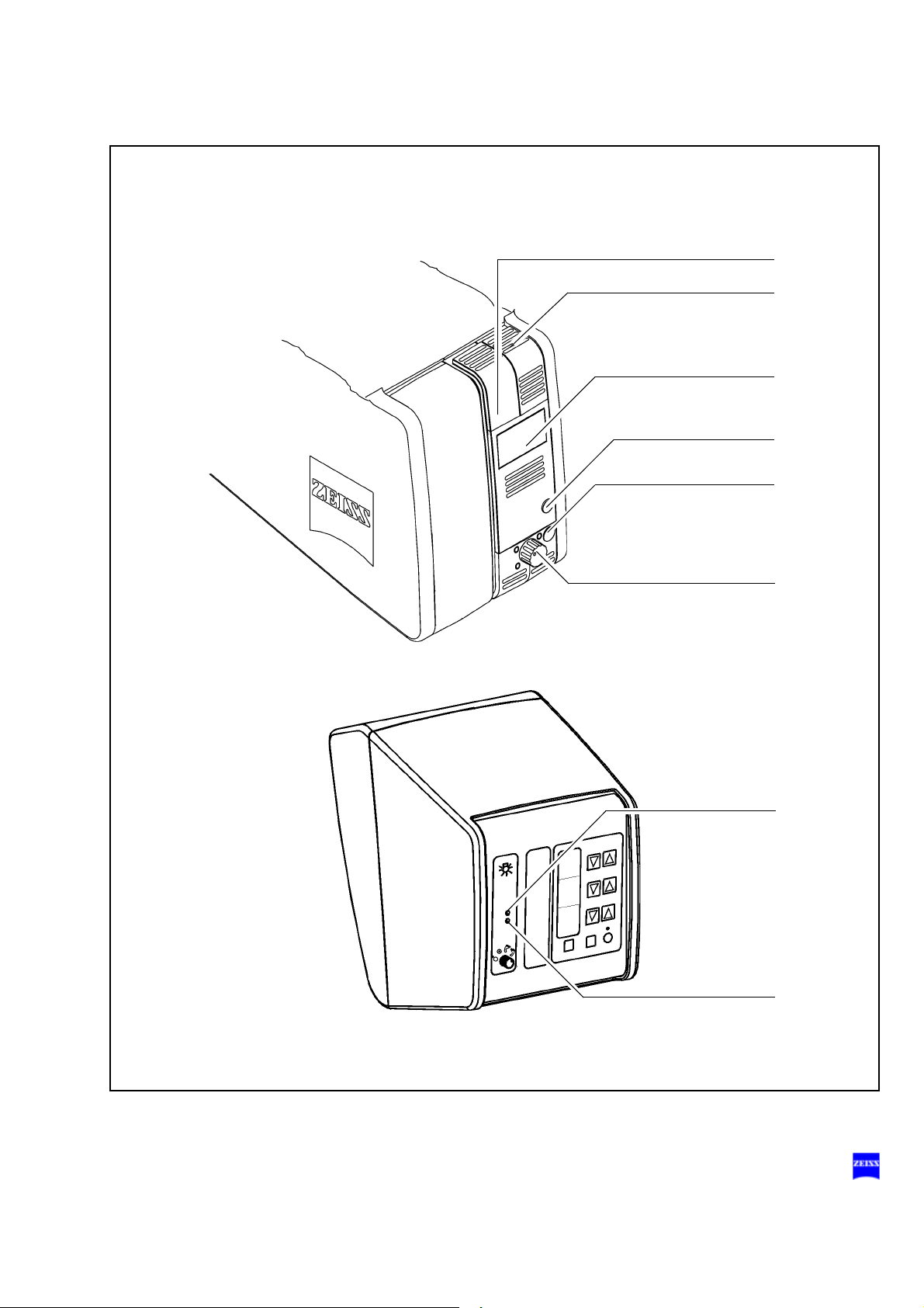
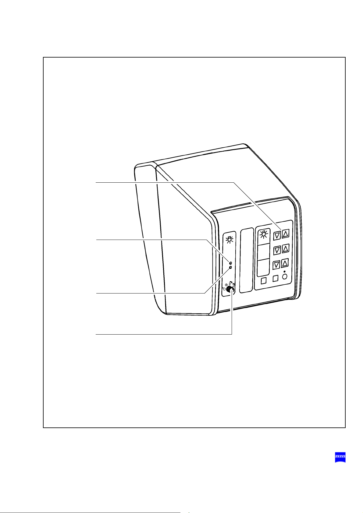
Safety devices of the suspension systems
1 Release bar
Allows non-sterile persons to release the magnetic brakes of the suspension system.
2 Adjustment screw for limiting downward movement
Use this knob to set the minimum vertical working distance from the
surgical field. Check this setting before
3 Locking knob
for the horizontal position of the suspension arm
Before removing or attaching a module (microscope, tube, etc.) move
the suspension arm into its horizontal position. Pull out the locking
knob and turn it clockwise or counterclockwise through 180°. At the
same time, slightly move the suspension arm up and down until the
lock snaps in. This prevents the suspension arm from uncontrollably
moving upward when insufficient weight is attached. After mounting
the module, unlock the suspension arm and perform the balancing
procedure.
each surgical procedure.
G-30-1682-en OPMI® Lumera® T Issue 4.0
Printed on 02. 02. 2009
Safety 33
1
1
2
3
G-30-1682-en OPMI® Lumera® T Issue 4.0
Printed on 02. 02. 2009

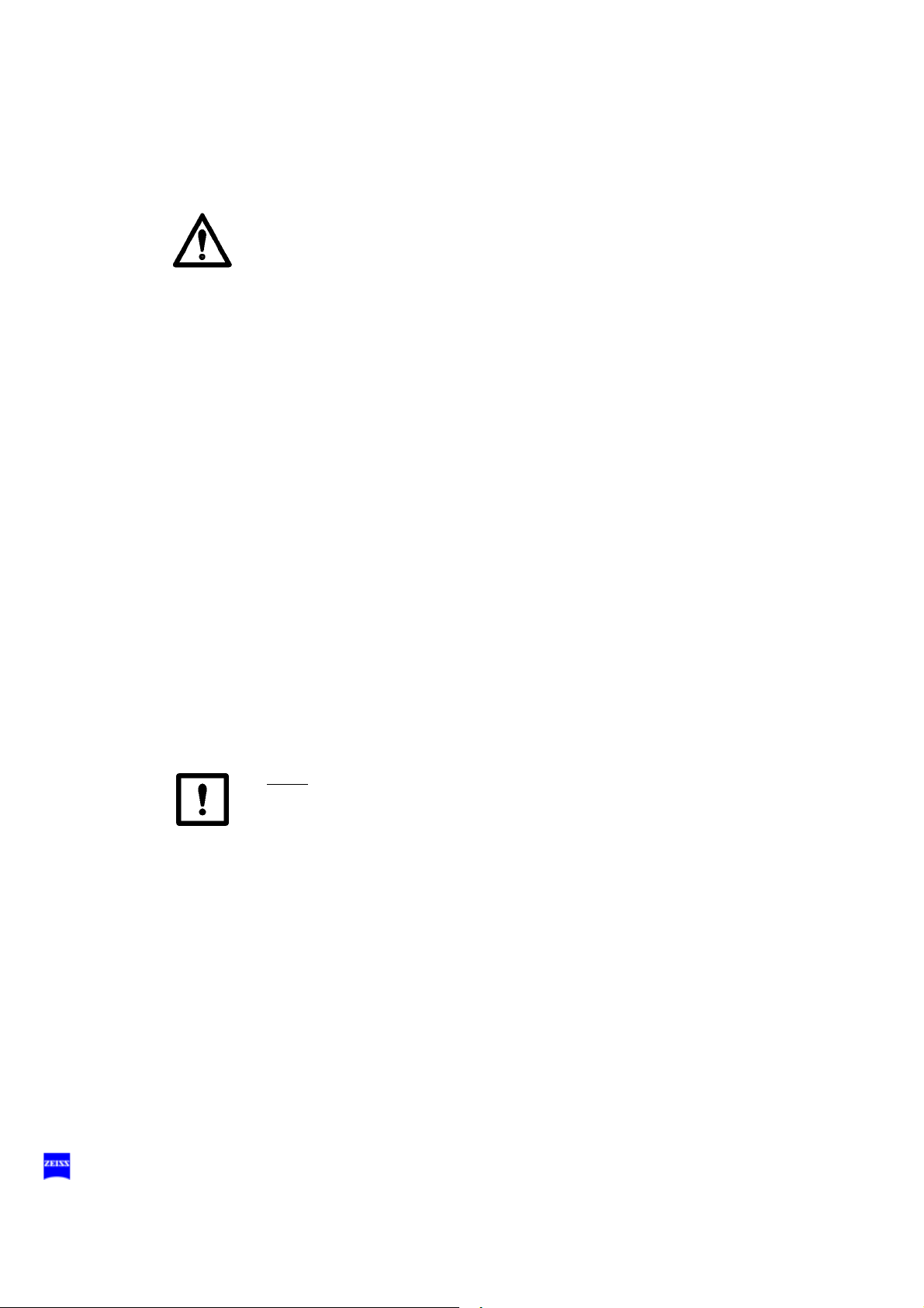
34 Safety
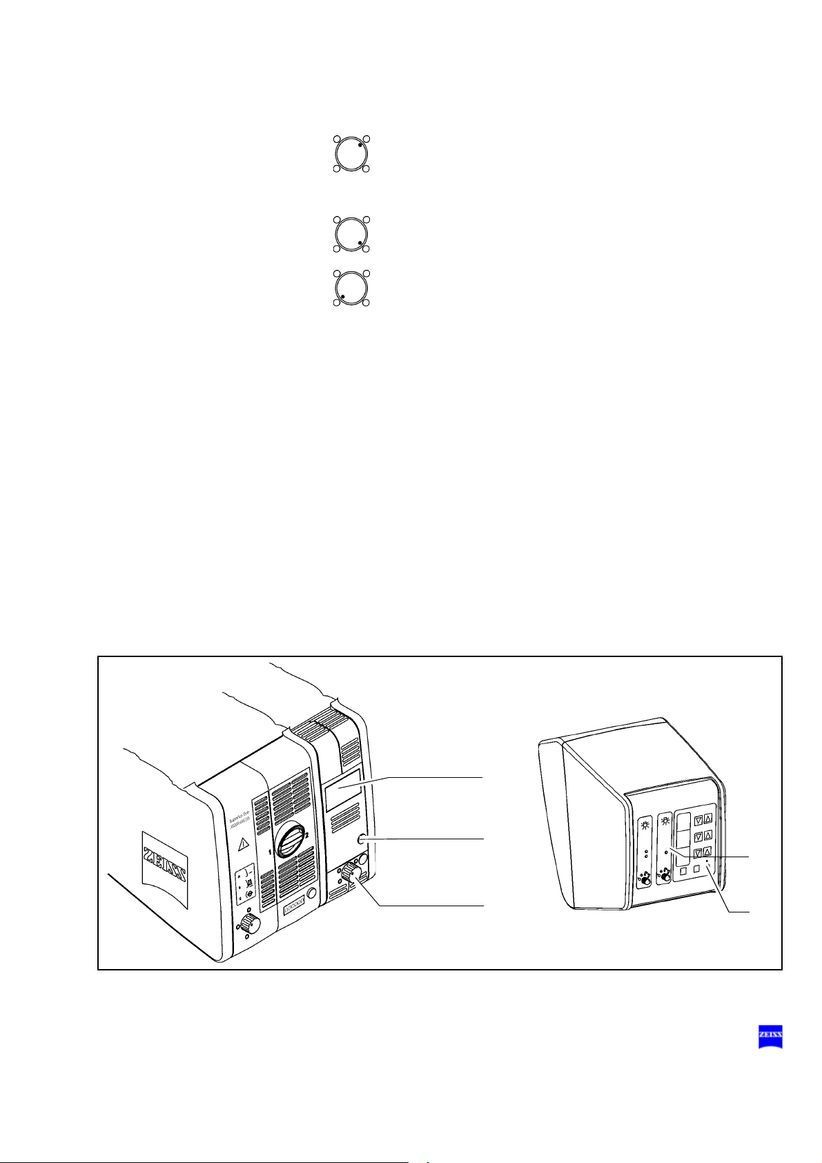
Halogen light source
1 Flap
The flap is the mechanical indicator for the operating status of the halogen lamps.
– When the flap is closed, the main lamp is operative.
– When the flap is open, the main lamp has failed. The backup lamp
2 Switching to the backup lamp
The lamp housing contains a backup lamp which is automatically
swung into the illumination beam path when the first lamp fails. If this
automatic function fails, you can switch on the backup lamp by
pressing this button.
3 Filter selector knob
The filter knob has four positions:
is on.
no filter
blue barrier filter (retina protection filter): use the blue barrier filter when operating on the eye. It protects the patient's
retina against unnecessary (blue) radiation and permits the
radiation exposure time to be increased by factor 3.
KK 40 filter:
to increase the color temperature
empty filter position
4 Yellow indicator lamp
– Lights when the main lamp has failed. In addition, open flap (1) on
the lamp module indicates that the main lamp has failed. The backup lamp is on.
– Blinks when the backup lamp has failed.
5 Manual function
When the manual function has been activated, all electrical control
systems are disabled. The lamp brightness is automatically adjusted
to a fixed setting.
G-30-1682-en OPMI® Lumera® T Issue 4.0
Printed on 02. 02. 2009
Safety 35
4
5
3
2
1
G-30-1682-en OPMI® Lumera® T Issue 4.0
Printed on 02. 02. 2009
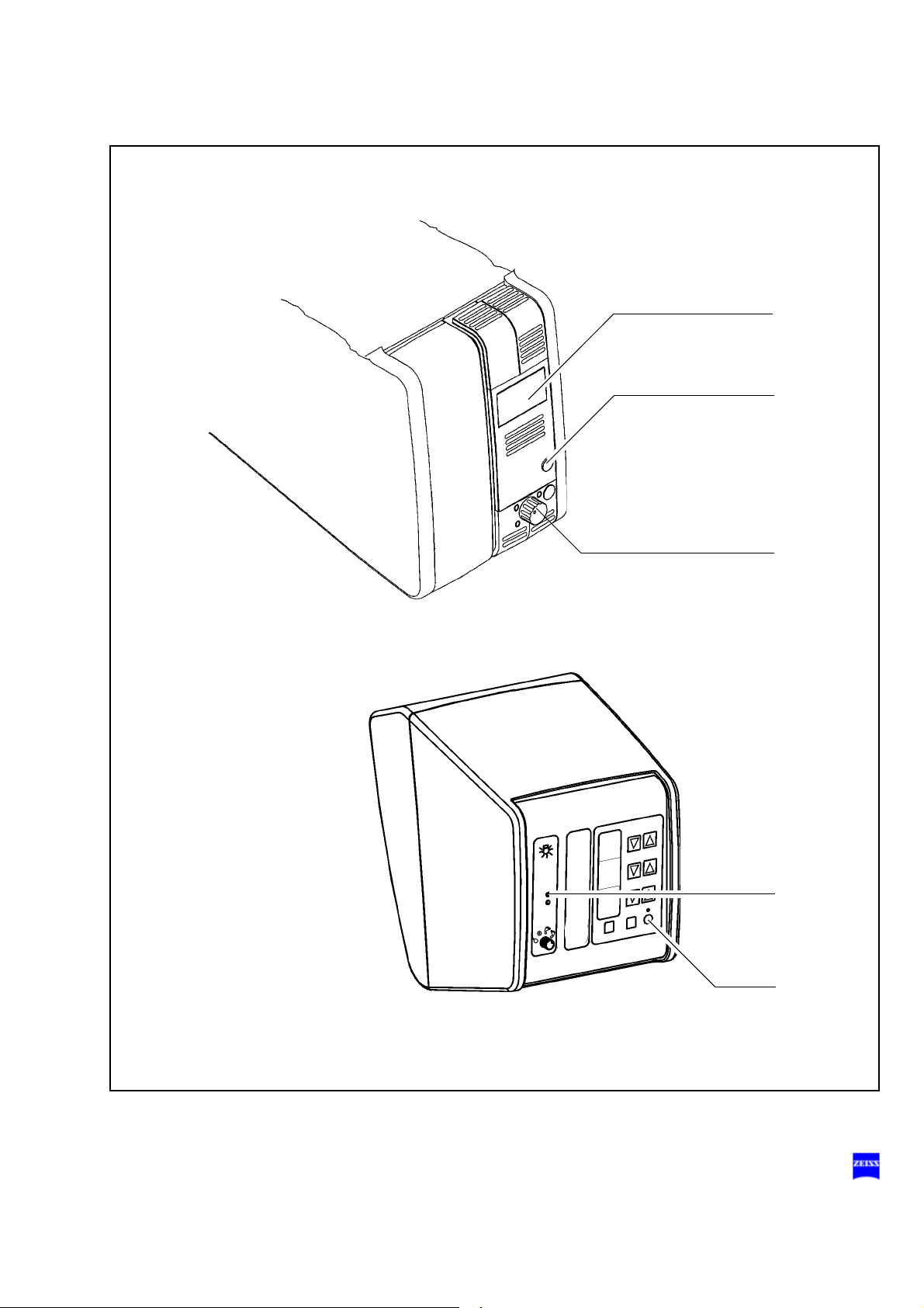
36 Safety
Superlux Eye light source
Warning!
The xenon lamp has a limited service life of 500 h.
If used beyond its maximum service life, the xenon lamp may explode.
• Replace the xenon lamp in good time.
• Reset the service hour counter to "0" after replacing the lamp.
Warning!
Lamp rupture (audible as a loud bang) may lead to jamming of the lamp
module and/or failure of the electronics modules.
• Before opening the lamp housing, make sure that the system is moved
to a position where neither the patient nor the user is put at risk by falling items.
• Do not continue using the system if the lamp module is jammed or the
illumination is no longer operational due to defective electronics modules. Inform our service department.
1 Switching to the backup lamp
The lamp module contains two xenon lamps. The second bulb is used
as a backup bulb which must be swung into the illumination beam path
if the first bulb fails.
• When the xenon lamp fails, open the lamp module as follows: Press
button (7). The lamp module is slightly ejected.
• Pull out the lamp module as far as it will go.
• Turn knob (1) through 180° until it snaps in place. This moves the
backup lamp into the illumination beam path.
• Push the lamp module all the way back into the lamp housing.
• Reset the service hour counter to "0". Use a pointed object and press
it into the recess of reset button (6).
G-30-1682-en OPMI® Lumera® T Issue 4.0
Printed on 02. 02. 2009
Safety 37
7
1
3
2
6
G-30-1682-en OPMI® Lumera® T Issue 4.0
Printed on 02. 02. 2009

38 Safety
2 Filter selector knob
The filter selector knob has the following positions, depending on the
light source used:
3 Indicator: backup lamp is in use
When the red segment in the knob (1) lights up, the backup bulb is in
use.
Note:
If the first lamp has failed and the backup lamp is in use, make sure to
have a backup lamp module ready at hand as a precaution.
No filter
Blue barrier filter (retina protection filter)
HaMode filter (standard)
485 nm fluorescence excitation filter (option)
4 Yellow indicator lamp
Lights when the bulb has failed, or if the lamp module is defective.
After activation and ignition of the backup bulb, the yellow indicator
lamp turns off again.
5 Manual function
When the manual function has been activated, all electrical control
systems are disabled. The bulb brightness is automatically adjusted to
a fixed setting.
Warning!
Software and hardware failure may increase the brightness of the xenon
light source, leading to retinal injury in the patient's eye.
If several successive beeps are emitted and the xenon lamp is lit when
the system is switched on, this indicates a malfunction of the xenon light
source.
• Attach a sign to the system stating it is out of order and contact our
service representative.
G-30-1682-en OPMI® Lumera® T Issue 4.0
Printed on 02. 02. 2009
Safety 39
4
5
1
2
3
G-30-1682-en OPMI® Lumera® T Issue 4.0
Printed on 02. 02. 2009
40 Safety
Superlux Eye light source with
integrated halogen light source (option)
Warning!
The xenon lamp has a limited service life of 500 h.
If used beyond its maximum service life, the xenon lamp may explode.
• Replace the xenon lamp in good time.
• Reset the service hour counter to "0" after replacing the lamp.
• For the lamp change procedure and how to reset the service hour
counter, see "Switching to the backup lamp" on page 38.
Warning!
Lamp rupture (audible as a loud bang) may lead to jamming of the lamp
module and/or failure of the electronics modules.
• Before opening the lamp housing, make sure that the system is moved
to a position where neither the patient nor the user is put at risk by falling items.
• Do not continue using the system if the lamp module is jammed or the
illumination is no longer operational due to defective electronics modules. Inform our service department.
1 Flap
The flap is the mechanical indicator for the operating status of the halogen lamps.
– When the flap is closed, the main lamp is operative.
– When the flap is open, the main lamp has failed. The backup lamp
is on.
2 Switching to the backup lamp
The lamp housing contains a backup lamp which is automatically
swung into the illumination beam path when the first lamp fails. If this
automatic function fails, you can switch on the backup lamp by
pressing this button.
3 Filter selector knob
The filter knob has four positions:
no filter
G-30-1682-en OPMI® Lumera® T Issue 4.0
Printed on 02. 02. 2009
Safety 41
4
3
2
1
5
blue barrier filter (retina protection filter): use the blue barrier filter when operating on the eye. It protects the patient's
retina against unnecessary (blue) radiation and permits the
radiation exposure time to be increased by factor 3.
KK 40 filter:
to increase the color temperature
empty filter position
4 Yellow indicator lamp
– Lights when the main lamp has failed. In addition, open flap (1) on
the lamp module indicates that the main lamp has failed. The backup lamp is on.
– Blinks when the backup lamp has failed.
5 Manual function
When the manual function has been activated, all electrical control
systems are disabled. The lamp brightness is automatically adjusted
to a fixed setting.
G-30-1682-en OPMI® Lumera® T Issue 4.0
Printed on 02. 02. 2009

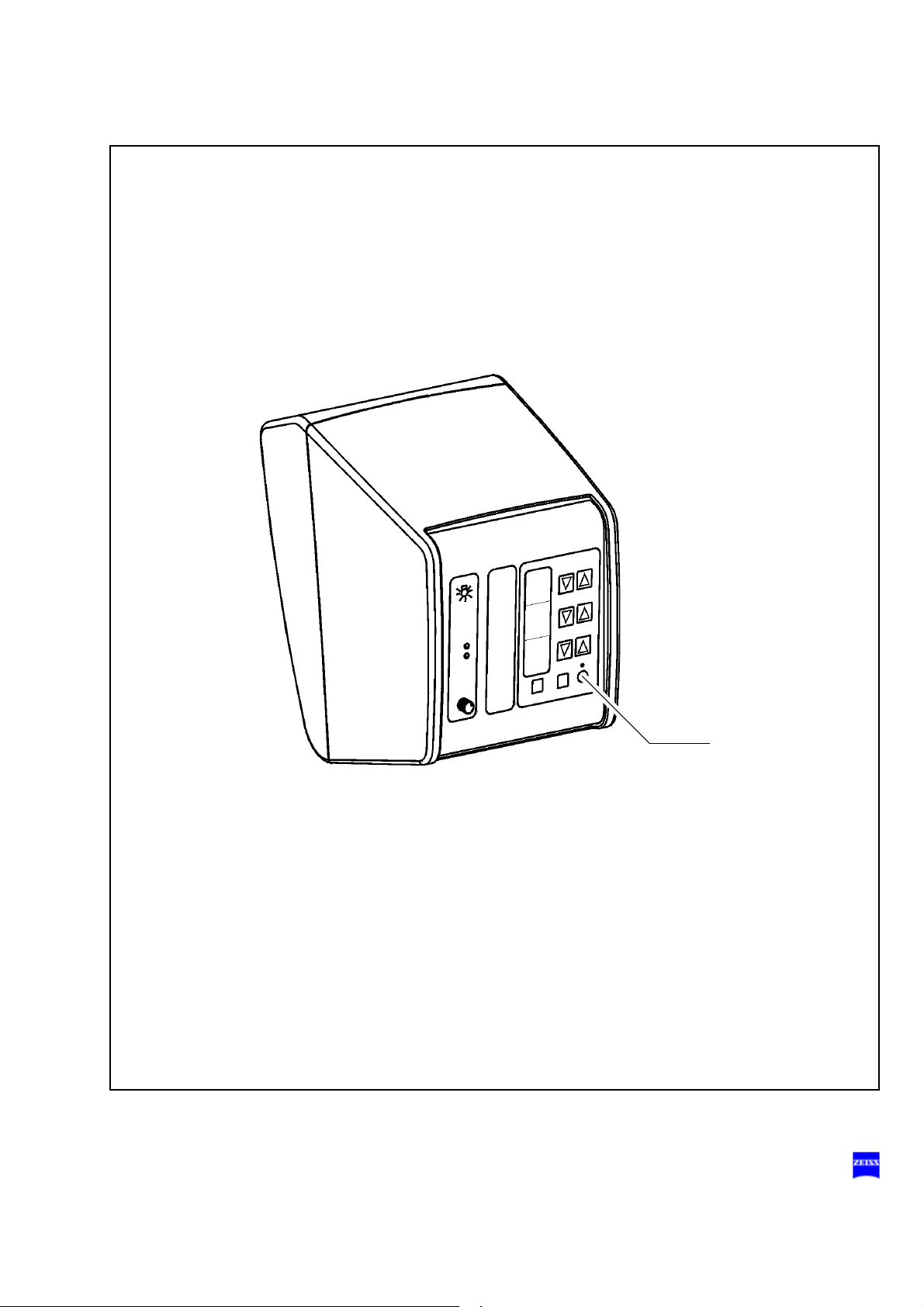
42 Safety
Manual function
1 Manual button
The Manual button permits you to switch to manual operation. The
motorized functions of the surgical microscope are deactivated. The
lamp brightness is automatically adjusted to a default setting. This
lamp brightness value is displayed in the first display field.
When you have switched to the manual mode, the yellow LED is lit
and the blinking text "MANUAL" appears in the third display field
The surgical microscope can no longer be operated via the foot control
panel, the handgrips or the control and display panel.
In the manual mode, you can use the foot control panel only to switch
the light source on and off, and you can unlock the magnetic brakes
by pressing the button on the microscope.
The manual mode is retained even if you switch the system off and
back on at the power switch.
Press the Manual button a second time to reactivate electronic control.
The basic mode is displayed again on the display and control panel.
G-30-1682-en OPMI® Lumera® T Issue 4.0
Printed on 02. 02. 2009
Safety 43
1
G-30-1682-en OPMI® Lumera® T Issue 4.0
Printed on 02. 02. 2009

44 Safety
OPMI Lumera T
Warning labels and notes
Caution:
Observe all warning labels and notes!
If any label is missing on your instrument or has become illegible, please
contact us or one of our authorized representatives. We will supply the
missing labels.
OPMI Lumera T (option)
G-30-1682-en OPMI® Lumera® T Issue 4.0
Printed on 02. 02. 2009

Safety 45
OPMI Lumera T
OPMI Lumera T with integrated assistant's microscope
G-30-1682-en OPMI® Lumera® T Issue 4.0
Printed on 02. 02. 2009

46 Safety
1
Superlux Eye
Superlux Eye
2
1
XXXXXX-XXXX-XXX
1
XXXXXX-XXXX-XXX
Light sources
G-30-1682-en OPMI® Lumera® T Issue 4.0
Printed on 02. 02. 2009

Safety 47
176164
S88 floor stand
G-30-1682-en OPMI® Lumera® T Issue 4.0
Printed on 02. 02. 2009
48 Safety
S88 floor stand with instrument tray option
G-30-1682-en OPMI® Lumera® T Issue 4.0
Printed on 02. 02. 2009
Safety 49
176164
S8 ceiling mount
G-30-1682-en OPMI® Lumera® T Issue 4.0
Printed on 02. 02. 2009
50 Safety
S81 ceiling mount
G-30-1682-en OPMI® Lumera® T Issue 4.0
Printed on 02. 02. 2009

Description
Description 51
Lumera T surgical microscope 54
Intended use 54
Description of components 54
Illumination system 60
Controls, displays, connections 64
Binocular tubes and eyepieces 72
Light sources 78
Halogen light source (option) 80
Superlux Eye light source 84
Superlux Eye with integrated halogen light source (option) 92
Identical components of the suspension systems 98
Suspension arm 98
Display field with control keys 100
S88 floor stand 102
Intended use 102
Description of components 103
Design 104
Stand base with column 106
Connection panel 108
Instrument tray (option) 110
Video monitor (option) 112
S8 ceiling mount 120
Intended use 120
Description of components 121
Design 122
Power switch with connector (option) 124
G-30-1682-en OPMI® Lumera® T Issue 4.0
Printed on 02. 02. 2009

52 Description
S81 ceiling mount 126
Intended use 126
Description of components 127
Design 128
Power switch, connector and socket (option) 130
OPMI Lumera T with integrated assistant's microscope
on S88 floor stand 132
Intended use 132
Design 132
OPMI Lumera T with integrated assistant's microscope
on S8 ceiling mount 134
Intended use 134
Design 134
OPMI Lumera T with integrated assistant's microscope
on S81 ceiling mount 136
Intended use 136
Design 136
Foot control panel 138
Intended use 138
Design 138
G-30-1682-en OPMI® Lumera® T Issue 4.0
Printed on 02. 02. 2009

Description 53
G-30-1682-en OPMI® Lumera® T Issue 4.0
Printed on 02. 02. 2009
54 Description
4
Lumera T surgical microscope
Intended use
The Lumera T surgical microscope has been designed for the magnified
visualization of the field of view during surgical procedures in ophthalmology. The illumination system of the surgical microscope features red
reflex illumination and surrounding field illumination, providing very effective illumination of the field of view and optimum visualization of the red
reflex.
Note:
The illumination system of the Lumera T surgical microscope contains a
UV blocking filter as a standard feature. This helps the surgeon to reduce
the risk of phototoxic retinal injury in the patient.
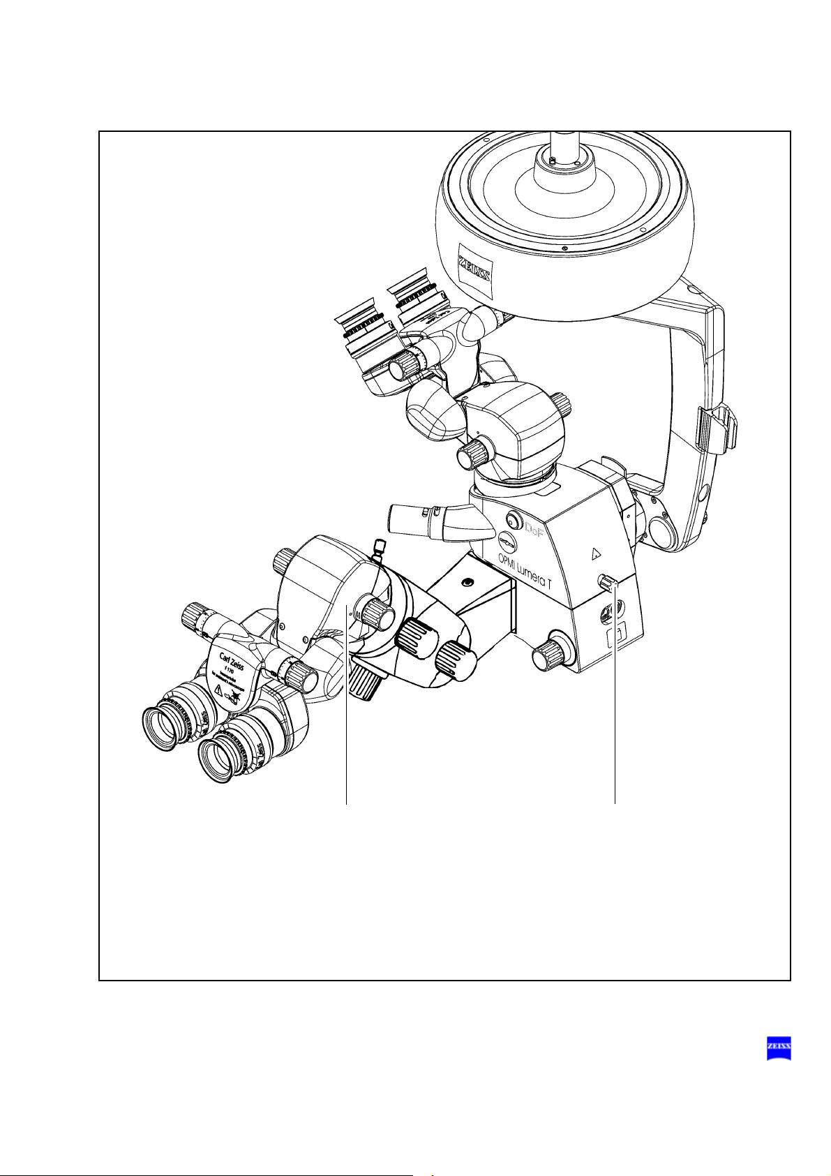
Description of components
The Lumera T surgical microscope comprises the following components:
1 X-Y coupling
The X-Y coupling allows motorized fine positioning of the surgical microscope in a horizontal plane. The range of travel is 40 mm x 40 mm.
The speed of travel can be set on the control panel of the suspension
system.
The X-Y coupling is provided with a recentering mechanism. When
you press reset button (2) or an appropriately programmed button of
the foot control panel (4),
– the X-Y coupling adopts its center position,
– the focusing system of the surgical microscope is reset to its initial
position (3).
G-30-1682-en OPMI® Lumera® T Issue 4.0
Printed on 02. 02. 2009
Description 55
1
2
3
G-30-1682-en OPMI® Lumera® T Issue 4.0
Printed on 02. 02. 2009

56 Description
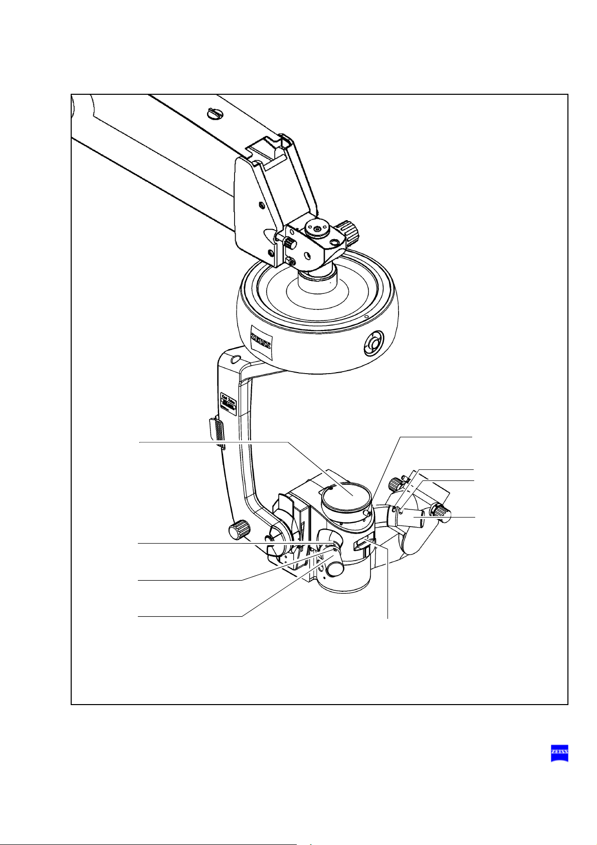
2 Support arm for the surgical microscope
The support arm incorporates a tilt device (3). This allows the viewing
direction of the surgical microscope to be adapted to the requirements
of the surgical field. Using the knob for fine tilt, you can position the
surgical microscope in a range from +90° to -90° (+ in the direction of
the surgeon and - in the opposite direction). The +90° setting is ideal
for surgery on patients in a seated position or lying on their side.
Caution:
Do not tilt the microscope beyond + / -90°, as this could damage the
microscope cable or the light guide.
3 Knob for tilt device
4 Surgical microscope
The apochromatic optics of the surgical microscope provide superb
optical quality. The microscope image displays optimum contrast and
excellent detail recognition along with a large depth of field. The bright
microscope image is a particular benefit in vitreoretinal surgery. A 1:6
ratio zoom system allows the magnification of the overall system to be
set as required by the surgical procedure. Two apochromatic objective
lenses with focal lengths of 175 mm and 200 mm are available for different working distances.
5 Invertertube for the main surgeon
6 Invertertube for the assistant
Tubes (5) and (6) offer an inverter function for ophthalmic applications.
The inverter is used to bring an inverted image created by a wideangle observation system into the correct position.
With the inverter deactivated, tubes (5) and (6) have the same optical
function as normal tiltable tubes.
7 180° tiltable binocular tube (option)
Due to its large tilt range, the tiltable binocular tube allows optimum
adaptation to extreme surgical conditions.
8 45° inclined binocular tube (option)
This tube is used as a viewing device for the surgeon. The viewing
angle of 45° allows work with minimum fatigue.
The standard equipment includes eyepieces with a magnification factor of
10x (option: 12.5x ).
G-30-1682-en OPMI® Lumera® T Issue 4.0
Printed on 02. 02. 2009

Description 57
5246
7
8
3
G-30-1682-en OPMI® Lumera® T Issue 4.0
Printed on 02. 02. 2009

58 Description
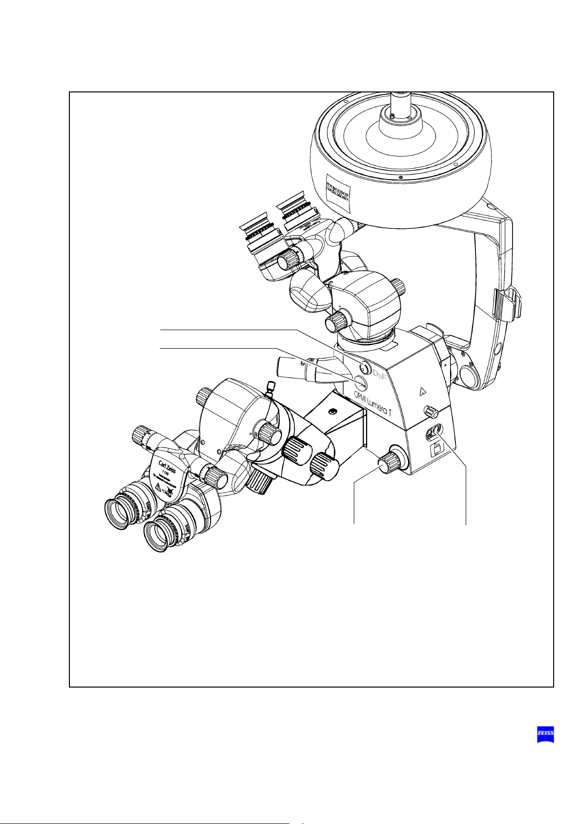
9 Integrated assistant's microscope
The integrated assistant's microscope in its standard version comes
as an integral part of OPMI Lumera T. The assistant sees the same
image as the main surgeon in the same image quality.
The assistant's microscope has two working positions. They are located on the right and left of the main surgeon at an angle of 90° to the
main surgeon's viewing direction. No locking mechanism has been
provided, allowing the assistant to move the assistant's microscope by
a certain amount out of the 90° position, if necessary.
Warning!
To prevent the assistant's microscope from moving downward of its
own accord when the main microscope is being tilted, the assistant's
microscope must be adjusted and locked in position using screw (9)
before surgery.
The assistant's microscope is equipped with a focusing system and a
5-step magnification changer. This enables the assistant to adjust his/
her microscope image independently of the main surgeon.
The binocular tube can be turned by ± 12° about the optical axis of the
assistant's microscope. In addition, the assistant's microscope can be
tilted by 15°. If the assistant finds the viewing angle too steep, an optical wedge (option) can be installed between the microscope body
and the binocular tube to permit horizontal viewing.
The standard equipment includes eyepieces with a magnification
factor of 10x, providing a low initial magnification. This offers the benefit of a wide field of view and an improved overview of the surgical
field. The assistant sees the red reflex in both eyepieces.
10 Locking screw for the integrated assistant's microscope
After adjusting the assistant's microscope as required, secure it in position using this screw.
Caution:
Please note the explanations given in the section "Adjusting the tilt motion" on page 174.
G-30-1682-en OPMI® Lumera® T Issue 4.0
Printed on 02. 02. 2009
Description 59
910
G-30-1682-en OPMI® Lumera® T Issue 4.0
Printed on 02. 02. 2009

60 Description
Illumination system
With red reflex illumination (stereo coaxial illumination) and surrounding
field illumination, the illumination system of the surgical microscope has
been specially tailored to the requirements of ophthalmic applications.
The illumination options provide very effective illumination of the field of
view and optimum visualization of the red reflex.
To protect the patient's eye, the illumination system is equipped with a
retina protection device and a blue barrier filter (retina protection filter.
The retinal protection device covers the patient's pupil and prevents light
from entering the patient's eye. It is integrated in the surgical microscope
and can be swung into the beam path when the red reflex is not needed.
The blue barrier filter (retina protection filter) reduces the retinal exposure
of the patient's and surgeon's eyes and permits the radiation exposure
time to be increased by factor 3. It can be swung into the beam path of the
light source in the suspension system.
The light is supplied by a light guide which directs the light from the light
source in the suspension system to the surgical microscope. To switch
the light source and the illumination systems on and off and to control their
brightness, you can use both the foot control panel and the control panel
of the suspension system.
Surrounding field illumination
The surrounding field illumination is integrated in the surgical microscope
and provides an optimally illuminated field of view with superb detail recognition. The brightness is controlled via the foot control panel or the suspension system. In addition, the intensity of the surrounding field illumination can be separately reduced or completely deactivated using knob (1)
on the surgical microscope.
Red reflex illumination
The red reflex illumination (stereo coaxial illumination) is integrated in the
surgical microscope and provides an optimally visible red reflex. For information on how to ensure optimum red reflex visualization, please see
page 172.
G-30-1682-en OPMI® Lumera® T Issue 4.0
Printed on 02. 02. 2009

Description 61
1
G-30-1682-en OPMI® Lumera® T Issue 4.0
Printed on 02. 02. 2009

62 Description
Illumination settings
The type of illumination required can be selected using knob (1) on the
surgical microscope.
Type of illumination
Red reflex illumination
This is the best setting to generate an optimum red reflex.
Glare from the sclera is effectively reduced as only the central field of view is illuminated.
Red reflex with surrounding field illumination
This setting permits clear visualization of the red reflex combined with illumination of the surrounding field of view.
Surrounding field illumination
This setting is used for illuminating the field of view if no red
reflex is required.
Surrounding field illumination with retina protection device
In this setting, a retina protection device is swung into the
surrounding field illumination beam path. It prevents light
from entering into the pupil and provides additional protection for the patient's eye against phototoxic injury.
Warning!
– Avoid looking directly into the light source, e.g. into the microscope ob-
jective lens or light guide!
– Adjust the illumination of patient's eye through the surgical micro-
scope to a level which ensures that the fundus is exposed to as little
light as possible.
– If no red reflex is required, swing the retinal protection device into the
beam path.
– When operating on the eye, use the blue barrier filter (retina protection
filter). It protects the patient's retina against unnecessary (blue) radiation and permits the radiation exposure time to be increased by
factor 3.
G-30-1682-en OPMI® Lumera® T Issue 4.0
Printed on 02. 02. 2009

Description 63
1
G-30-1682-en OPMI® Lumera® T Issue 4.0
Printed on 02. 02. 2009
64 Description
Controls, displays, connections
1 Securing screw
– Prevents the coupling on the suspension arm from coming loose.
2 X-Y coupling
3 Reset button
– Recenters the X-Y coupling.
– Resets the focus to its initial position in the focusing range
Note:
Press this button to start the recentering movement. To stop this
movement, press the button again.
You can also stop the recentering movement by briefly tipping on one
of the buttons on the foot control panel.
4 Cable and light guide clip
5 Support arm with tilt device
6 Knob
for setting the tilt angle of the surgical microscope;
+90° in the direction of the surgeon,
-90° in the opposite direction.
7 Arrows indicating the focusing range
If the dot is located between the two arrow tips, the focusing system
of the surgical microscope is in its starting position.
G-30-1682-en OPMI® Lumera® T Issue 4.0
Printed on 02. 02. 2009

Description 65
1
2
4
5
6
3
7
G-30-1682-en OPMI® Lumera® T Issue 4.0
Printed on 02. 02. 2009

66 Description
8 Dust cover
9 Switch for unlocking the magnetic brakes of the suspension system
10 Clamp for asepsis caps
11 Handgrips for positioning the surgical microscope
With asepsis caps attached, the handgrips are used to position the microscope and unlock the magnetic brakes.
– Handgrip turned Magnetic brakes are unlocked, the de-
– Handgrip not turned Magnetic brakes are locked, the de-
12 Display of the zoom system's magnification factor
13 Securing screw for tubes or accessories
vice can be moved as required.
vice cannot be moved.
G-30-1682-en OPMI® Lumera® T Issue 4.0
Printed on 02. 02. 2009
Description 67
12
11
11
8
13
10
9
9
10
G-30-1682-en OPMI® Lumera® T Issue 4.0
Printed on 02. 02. 2009

68 Description
14 DeepView button (depth of field (DoF) management system)
Allows you to optimize the light transmission or depth of field, depending on the application involved. When this function is deactivated
(LED not lit), the microscope is optimized for light transmission. When
this function is activated (green LED is lit), the microscope is automatically set to optimized depth of field in accordance with the selected
magnification. This mode is primarily recommended for procedures on
the anterior segment where high depth of field is required.
The next time the system is switched on, the mode last selected will
be activated.
15 Manual adjustment of the zoom system in the emergency mode
16 Selection knob for different types of illumination
Red reflex illumination
This is the best setting to generate an optimum red reflex. Glare
from the sclera is effectively reduced as only the central field of
view is illuminated.
Red reflex with surrounding field illumination
This setting permits clear visualization of the red reflex combined with illumination of the surrounding field of view.
Surrounding field illumination
This setting is used for illuminating the field of view if no red reflex is required.
Surrounding field illumination with retina protection device
In this setting, a retina protection device is swung into the surrounding field illumination beam path. It prevents light from entering into the pupil and provides additional protection for the
patient's eye against phototoxic injury.
17 Light guide connector
Caution:
Take care not to damage the light guide connector and light guide!
• Always insert the correct end of the light guide into the light guide con-
nector. For correct mounting, please see the label provided under the
light guide connector (17).
G-30-1682-en OPMI® Lumera® T Issue 4.0
Printed on 02. 02. 2009
Description 69
15
16
17
14
G-30-1682-en OPMI® Lumera® T Issue 4.0
Printed on 02. 02. 2009

70 Description
The integrated assistant's microscope comprises the following
components:
18 Clamping screw for locking the coobservation tube in position
within the 12° range of rotation. After adjusting the assistant's microscope as required, secure it in position using this screw. Firmly tighten
the clamping screw by hand.
19 Coobservation tube
– Invertertube for the assistant (standard)
20 Knob for setting the interpupillary distance (54 mm to 76 mm)
The correct position has been reached when the two eyepiece images
merge into one.
21 Inverter selection knob
The inverter can be turned about 360° and snaps in at the two defined
positions.
22 Focusing knob
for focusing the assistant's microscope independently of the main surgeon.
23 Manual magnification changer
24 Clamping screw for locking the tilt position
of the integrated assistant's microscope within the 15° tilt range. After
tilting the integrated assistant's microscope as required, secure it in
position using this screw. Firmly tighten the clamping screw by hand.
25 Clamping screw for locking the assistant's microscope in position
After adjusting the assistant's microscope as required, secure it in position using this screw. Firmly tighten the clamping screw by hand.
G-30-1682-en OPMI® Lumera® T Issue 4.0
Printed on 02. 02. 2009
Description 71
19
22 23
24
18
25
2120
G-30-1682-en OPMI® Lumera® T Issue 4.0
Printed on 02. 02. 2009

72 Description
Binocular tubes and eyepieces
You can mount a 180° tiltable tube, an Invertertube or a 45° inclined tube
on the Lumera T surgical microscope as required (see the following
pages).
180° tiltable tube
1 PD adjustment knob
The correct position has been reached when the two eyepiece images
merge into one. You can read off the interpupillary distance set on the
adjustment knob.
2 180° tiltable tube
3 Eyepiece mount
45° inclined tube
4 45° inclined tube
5 PD adjustment knob
The correct position has been reached when the two eyepiece images
merge into one. You can read off the interpupillary distance set on the
adjustment knob.
6 Eyepiece mount
G-30-1682-en OPMI® Lumera® T Issue 4.0
Printed on 02. 02. 2009
Description 73
4
5
1
2
3
6
G-30-1682-en OPMI® Lumera® T Issue 4.0
Printed on 02. 02. 2009

74 Description
Invertertube™
The tiltable tube has an inverter function and has been designed for ophthalmic use. Many wide-angle observation systems for the posterior segment of the eye provide an inverted intermediate image which is viewed
through the surgical microscope. The inverter is used to erect an inverted
image.
When activating the wide-angle observation system, you must also activate the inverter of the tiltable tube. When swinging out the wide-angle observation system, you must also deactivate the inverter of the tiltable tube
again.
With the inverter deactivated, the tiltable tube has the same optical function as a normal tiltable tube.
To ensure sterility, the controls can be equipped with sterilizable caps.
1 Invertertube - 110° tiltable binocular tube
2 Eyepiece mount
3 Knob for setting the interpupillary distance (54 mm to 76 mm)
The correct position has been reached when the two eyepiece images
merge into one.
4 Inverter selection knob
The inverter can be turned about 360° and snaps in at the two defined
positions.
5 Symbol for deactivated inverter on the inverter selection knob
6 Symbol for activated inverter on the inverter selection knob
7 Lateral tilt axis
-10° to +100°
8 Cat. No.
If you have any questions for our service staff, please always specify
the relevant Cat. No.
G-30-1682-en OPMI® Lumera® T Issue 4.0
Printed on 02. 02. 2009
Description 75
1
7
23 4
5
6
8
G-30-1682-en OPMI® Lumera® T Issue 4.0
Printed on 02. 02. 2009

76 Description
Widefield eyepieces with magnetic coupling
Note:
When the eyepiece has been removed from the tube, please remember
that it is equipped with a magnetic coupling. Attached eyepieces produce
a very minor magnetic field, i.e. the usual regulations for the handling of
magnets must only be observed with non-attached eyepieces.
• Do not place the eyepiece near instruments which may be magnetiz-
able.
• Do not place the eyepiece on sensitive electronic instruments such as
infusion pumps, heart pacemakers, measuring instruments or magnetic data carriers such as disks, audio/video tapes or credit cards.
• Always store the eyepiece in its original packaging, when not using it.
1 Eyecup
Always adjust the eyecups in such a way that the entire field of view
can be seen.
– Viewing with eyeglass-
Screw in the eyecups all the way.
es:
– Viewing without eye-
glasses:
Adapt the eyecups to the viewer's field
of view by screwing them outward.
2 Diopter setting ring
The eyepieces enable you to set your prescription between -8 D and
+5 D. Eyeglass wearers using their glasses during work should set the
diopter setting ring to 0. Turn the ring until the optimum setting has
been achieved. An integrated brake holds the setting ring in the position set.
3 Diopter scale
For reading off the prescription set.
G-30-1682-en OPMI® Lumera® T Issue 4.0
Printed on 02. 02. 2009

Description 77
1
2
3
G-30-1682-en OPMI® Lumera® T Issue 4.0
Printed on 02. 02. 2009

78 Description
Light sources
The suspension system is equipped either with a halogen light source, a
Superlux Eye light source or with a Superlux Eye light source with an additional, integrated halogen light source (option).
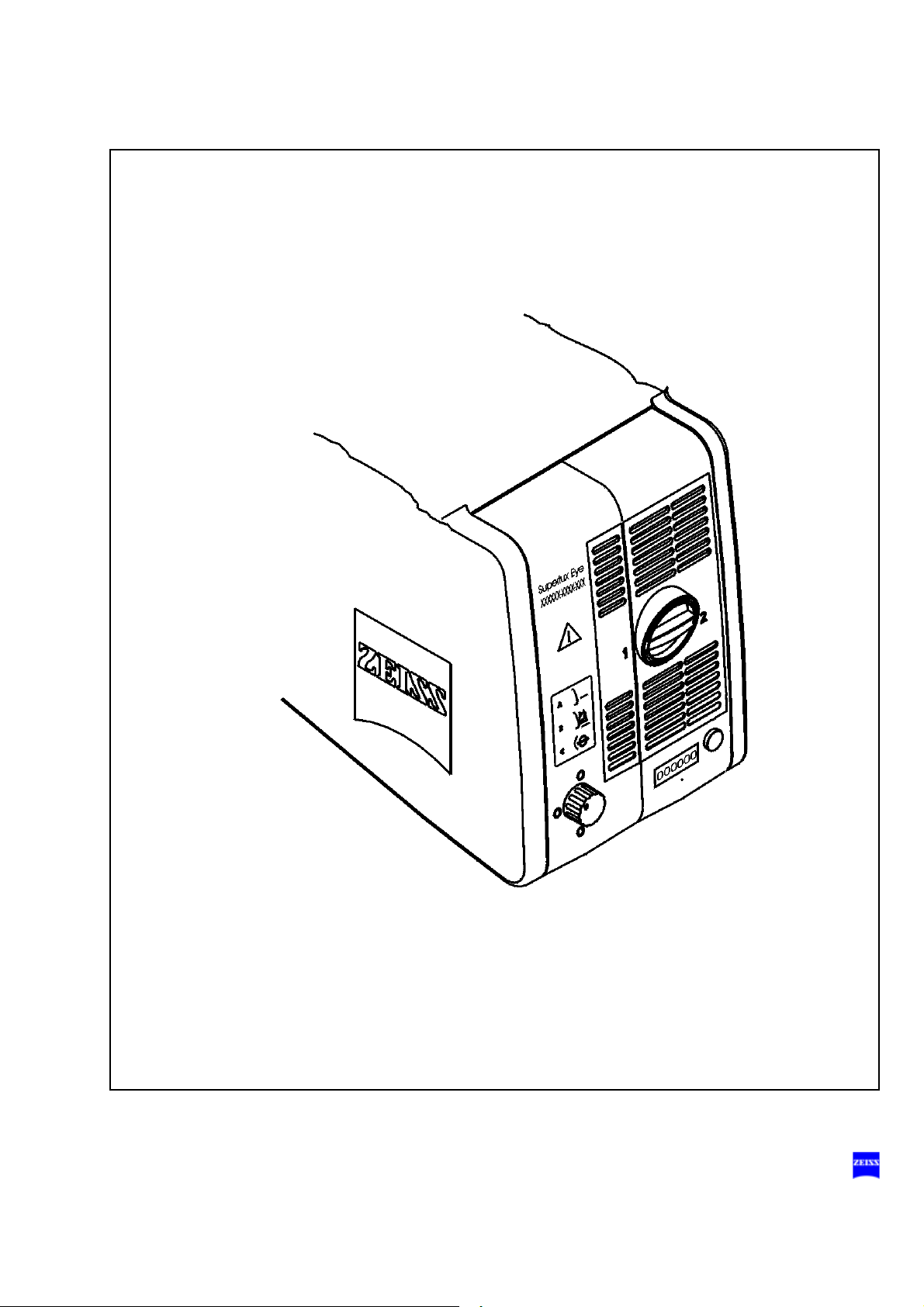
1 Superlux Eye light source
This illumination system comprises a xenon lamp featuring fiber illumination. The xenon lamp generates light whose spectrum resembles
that of natural daylight. Regardless of the brightness setting, the color
temperature of the light always remains the same. Normal daylight film
without any additional conversion filters can therefore be used for photographic documentation. For changing the light spectrum, two Superlux Eye light sources with two xenon lamps and different swing-in
filters are available. The second lamp is used as a backup lamp which
must be manually swung into the illumination beam path when the first
lamp fails. You have to pull out the lamp module all the way before
being able to swing in the backup lamp.
Warning!
When using the Superlux Eye light source, only operate the system with
special xenon lamps approved by Carl Zeiss for ophthalmic surgery. If any
other than Carl Zeiss-approved xenon lamps are used, there is the risk of
severe injury to the patient's eye.
2 Halogen light source (option)
This illumination system comprises a light source featuring fiber illumination. The lamp housing contains a backup lamp which is automatically swung into the illumination beam path when the first lamp fails.
If required, the light source can be equipped with a second lamp
housing so that two separate light sources are available for fiber illumination. The second light source can be used, for example, for a fiber
slit lamp.
3 Superlux Eye illumination system with additional integrated halogen il-
lumination (option)
The additional, integrated halogen illumination is a second illumination
system suitable e.g. for the use of a fiber slit lamp.
G-30-1682-en OPMI® Lumera® T Issue 4.0
Printed on 02. 02. 2009
Description 79
2
1
3
G-30-1682-en OPMI® Lumera® T Issue 4.0
Printed on 02. 02. 2009
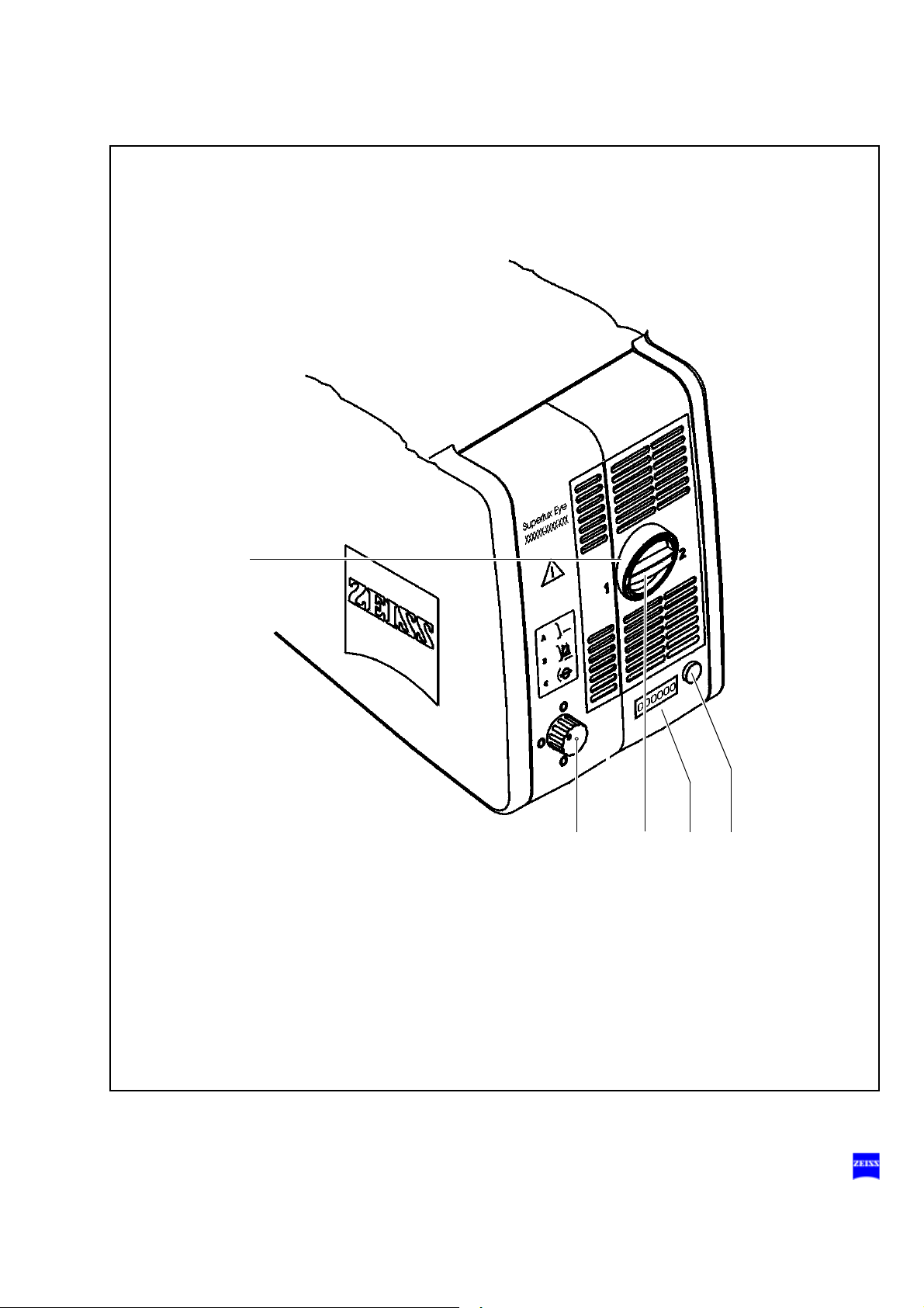
80 Description
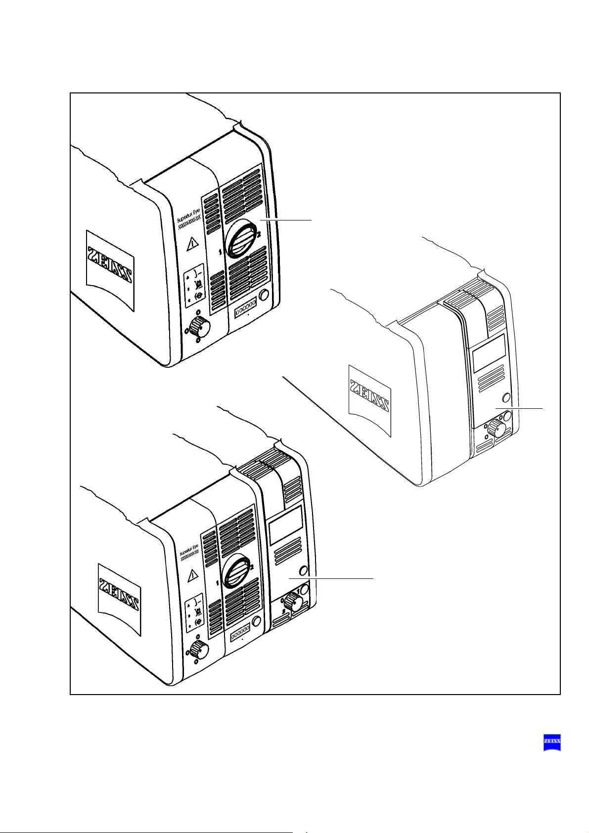
Halogen light source (option)
The suspension system is equipped with a light source for fiber illumination. The lamp housing contains a backup lamp which is automatically
swung into the illumination beam path when the first lamp fails. If required,
the light source can be equipped with a second lamp housing so that two
separate light sources are available for fiber illumination.
1 Lamp module
2 Ventilation grid
Do not cover the ventilation grid! For example, drapes could be covering the grid. This can lead to overheating of the lamp modules and
to lamp failure.
3 Flap
The flap is the mechanical indicator for the operating status of the halogen lamps.
– When the flap is closed, the main lamp is operative (green light (9)
is on).
– When the flap is open, the main lamp has failed. The backup lamp
is used (yellow light (8) is on).
4 Manual activation of the backup lamp
If the automatic activation function fails, press this button to switch on
the backup lamp.
5 Opening the lamp module
When you press this button, the lamp module is slightly ejected. Pull
out the lamp module all the way for lamp change.
6 Filter selector knob
The filter selector knob has four positions:
no filter
blue barrier filter (retina protection filter): when operating on
the eye, always use this filter to protect the patient's eye
against unnecessary radiation (retinal injury).
KK 40 filter:
to increase the color temperature
empty filter position
G-30-1682-en OPMI® Lumera® T Issue 4.0
Printed on 02. 02. 2009
Description 81
8
9
1
2
3
4
5
6
G-30-1682-en OPMI® Lumera® T Issue 4.0
Printed on 02. 02. 2009

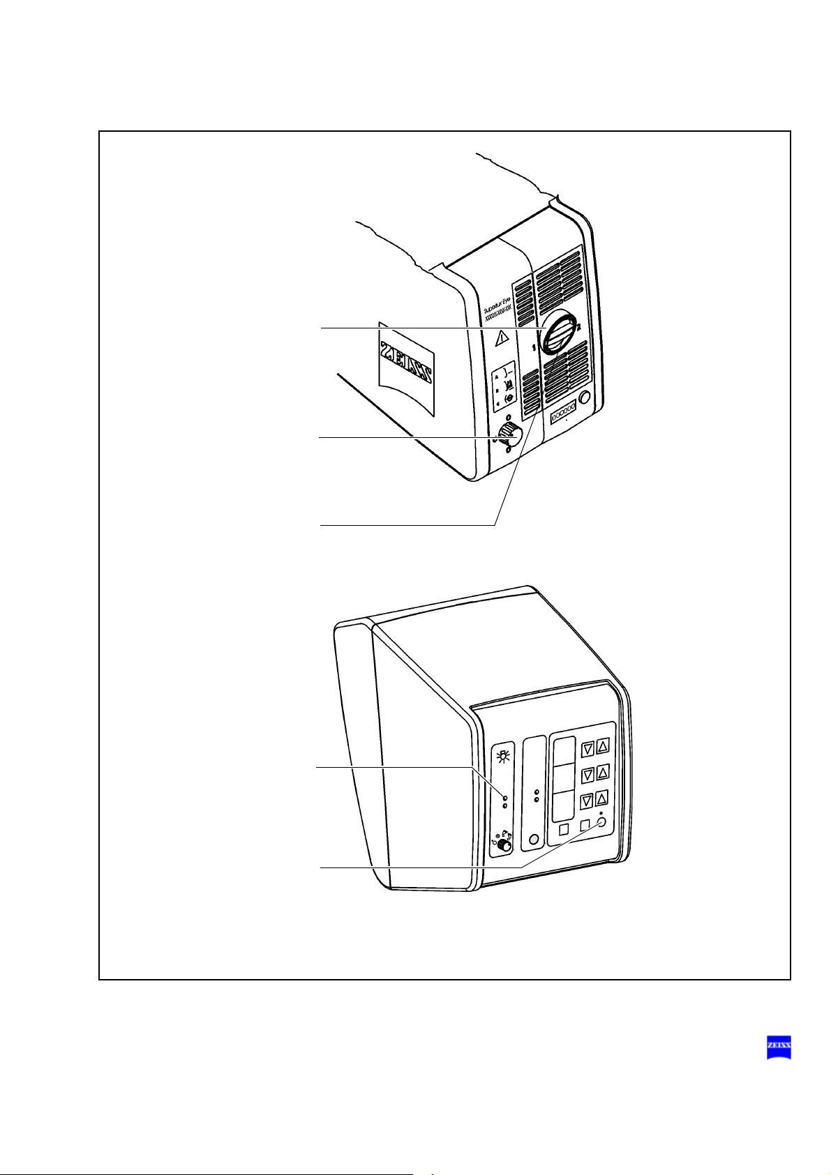
82 Description
7 Brightness control
Brightness can be adjusted using the two keys (7) on the control
panel.
Warning!
Too much light intensity (brightness setting is too high) or excessive radiation exposure times may lead to retinal injury in the patient's eye.
• Adjust the illumination intensity as required for the light source used
and the radiation exposure time. You will find the values recommended by Carl Zeiss in the table "Maximum radiation exposure times" on
page 29.
Note:
If the suspension system has two lamp housings, you can also adjust
the brightness of lamp 1 by pressing the appropriate button(s) on the
foot control panel.
8 Yellow indicator lamp
– Lights when the main lamp has failed. The backup lamp is on.
– Blinks when the backup lamp has failed.
9 Green indicator lamp
Lights when the respective light source has been switched on.
10 Selector:
The light source is off.
The light source is on.
The light source can be switched on/off on the left-hand side
of the foot control panel.
The light source can be switched on/off on the right-hand
side of the foot control panel.
Note:
If two lamp housings are available, you can set the selector switch in such
a way
– that one light source each can be switched on/off on the left-hand and
right-hand side of the foot control panel,
– or that both light sources can be switched on/off on the left-hand or
right-hand side of the foot control panel.
G-30-1682-en OPMI® Lumera® T Issue 4.0
Printed on 02. 02. 2009
Description 83
7
9
8
10
0
,
7
G-30-1682-en OPMI® Lumera® T Issue 4.0
Printed on 02. 02. 2009
84 Description
Superlux Eye light source
Warning!
The xenon lamp has a limited service life of 500 h.
If used beyond its maximum service life, the xenon lamp may explode.
• Replace the xenon lamp in good time.
• Reset the service hour counter to "0" after replacing the lamp.
The Superlux Eye light source is equipped with a xenon lamp, a blue barrier filter (retina protection filter) and an optionally selectable filter. The
xenon lamp generates light whose spectrum resembles that of natural
daylight. Regardless of the brightness setting, the color temperature of
the light always remains the same. This permits normal daylight film
without any additional conversion filters to be used for photographic documentation. The second xenon lamp is used as a backup lamp which has
to be swung into the illumination beam path when the first xenon lamp
fails.
– The standard version of the Superlux Eye light source is marked on
the front panel by the number 304977-9011-500. In addition to the
blue barrier filter (retina protection filter), this light source contains the
HaMode filter which generates a light spectrum similar to that of the
halogen light source.
– The Superlux Eye light source is optionally available with the 485 mm
fluorescence excitation filter that makes fluorescent areas visible. This
version, which is also equipped with the blue barrier filter (retina protection filter), is marked on the front panel by the number 3049779012-500.
Note:
Do not cover the ventilation grid! For example, drapes could be covering
the grid. This can lead to overheating of the lamp modules and to lamp
failure.
G-30-1682-en OPMI® Lumera® T Issue 4.0
Printed on 02. 02. 2009
Description 85
G-30-1682-en OPMI® Lumera® T Issue 4.0
Printed on 02. 02. 2009
86 Description
1 Lamp module
2 Manual activation of the backup lamp
• When the xenon lamp fails, open the lamp module as follows:
• Press button (7). The lamp module is slightly ejected.
• Pull out the lamp module as far as it will go.
• Turn knob (2) through 180° until it snaps in. This moves the backup
lamp into the illumination beam path.
• Push the lamp module all the way back into the lamp housing.
• Reset the service hour counter to "0". Use a pointed object and press
it into the recess of reset button (6).
Note:
When inserting a new lamp module, make sure that knob (2) is set to
"1“. If the first lamp fails, you switch to the second lamp in logical sequence.
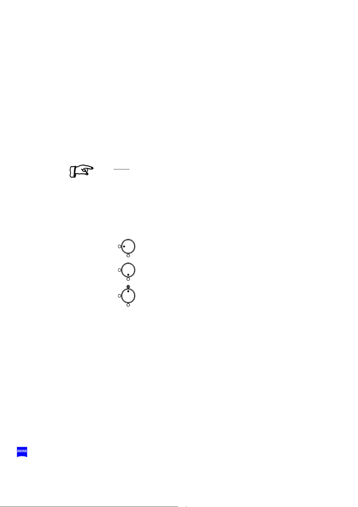
3 Indicator: backup lamp is in use
When the red segment in knob (2) lights up, the backup lamp is in use.
4 Filter selector knob
The filter selector knob has the following positions:
no filter
blue barrier filter (retina protection filter)
HaMode filter (standard)
485 nm fluorescence excitation filter (option)
G-30-1682-en OPMI® Lumera® T Issue 4.0
Printed on 02. 02. 2009

Description 87
2
4
3
1
5 67
G-30-1682-en OPMI® Lumera® T Issue 4.0
Printed on 02. 02. 2009

88 Description
5 Counter
The counter records the service hours of the xenon lamp in the Superlux Eye light source.
• Change the xenon lamps after about 500 hours of operation to avoid
any explosion of the xenon lamps. Then reset the counter to "0" by
pressing reset button (6).
6 Reset button
The reset button resets the service hour counter to "0".
7 Opening the lamp module
When you press this button, the lamp module is slightly ejected.
• For changing the lamp, pull out the lamp module as far as it will go.
Turn knob (2) through 180° until it snaps in. This moves the backup
lamp into the illumination beam path.
G-30-1682-en OPMI® Lumera® T Issue 4.0
Printed on 02. 02. 2009
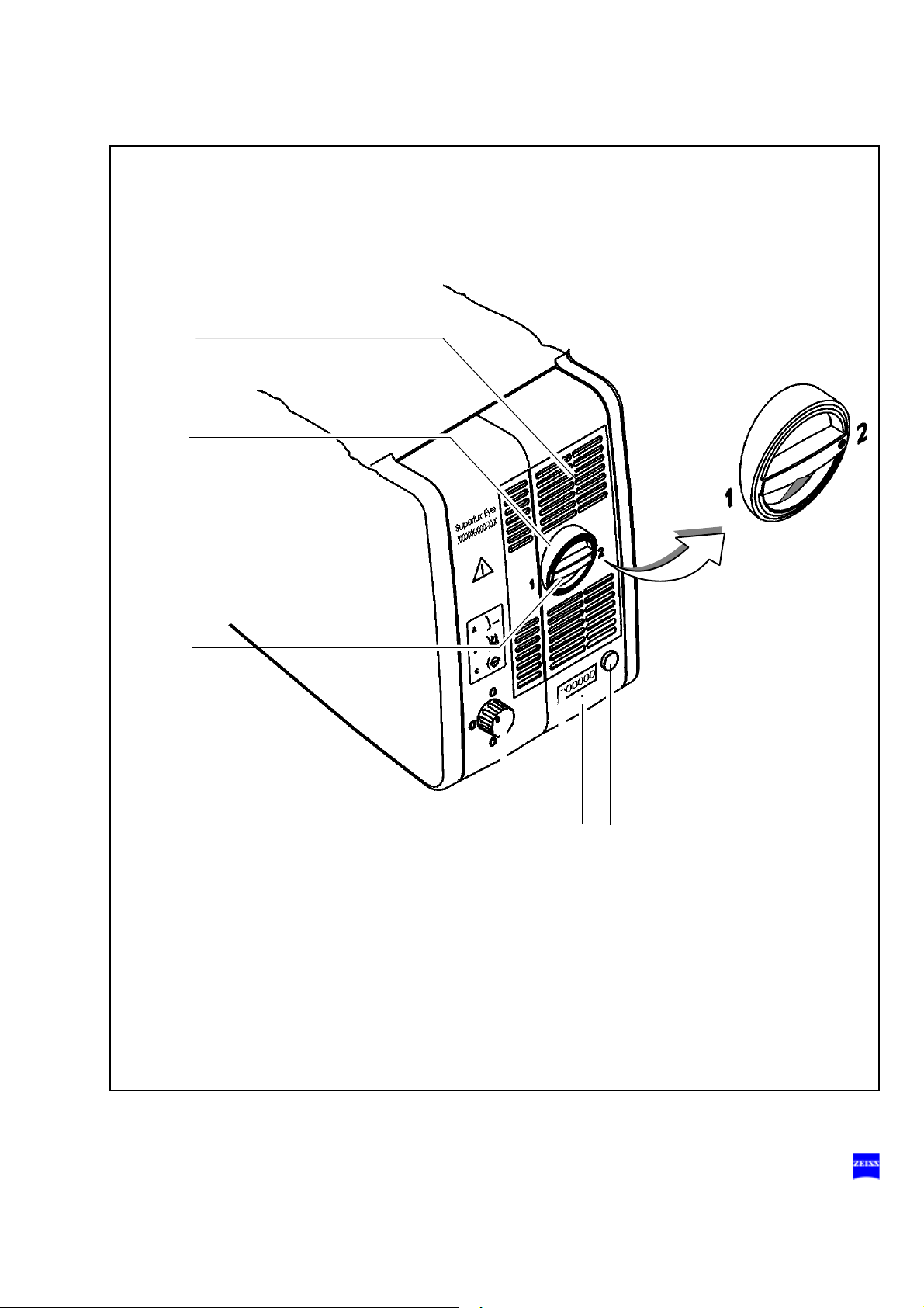
Description 89
2
4
3
1
5 67
G-30-1682-en OPMI® Lumera® T Issue 4.0
Printed on 02. 02. 2009
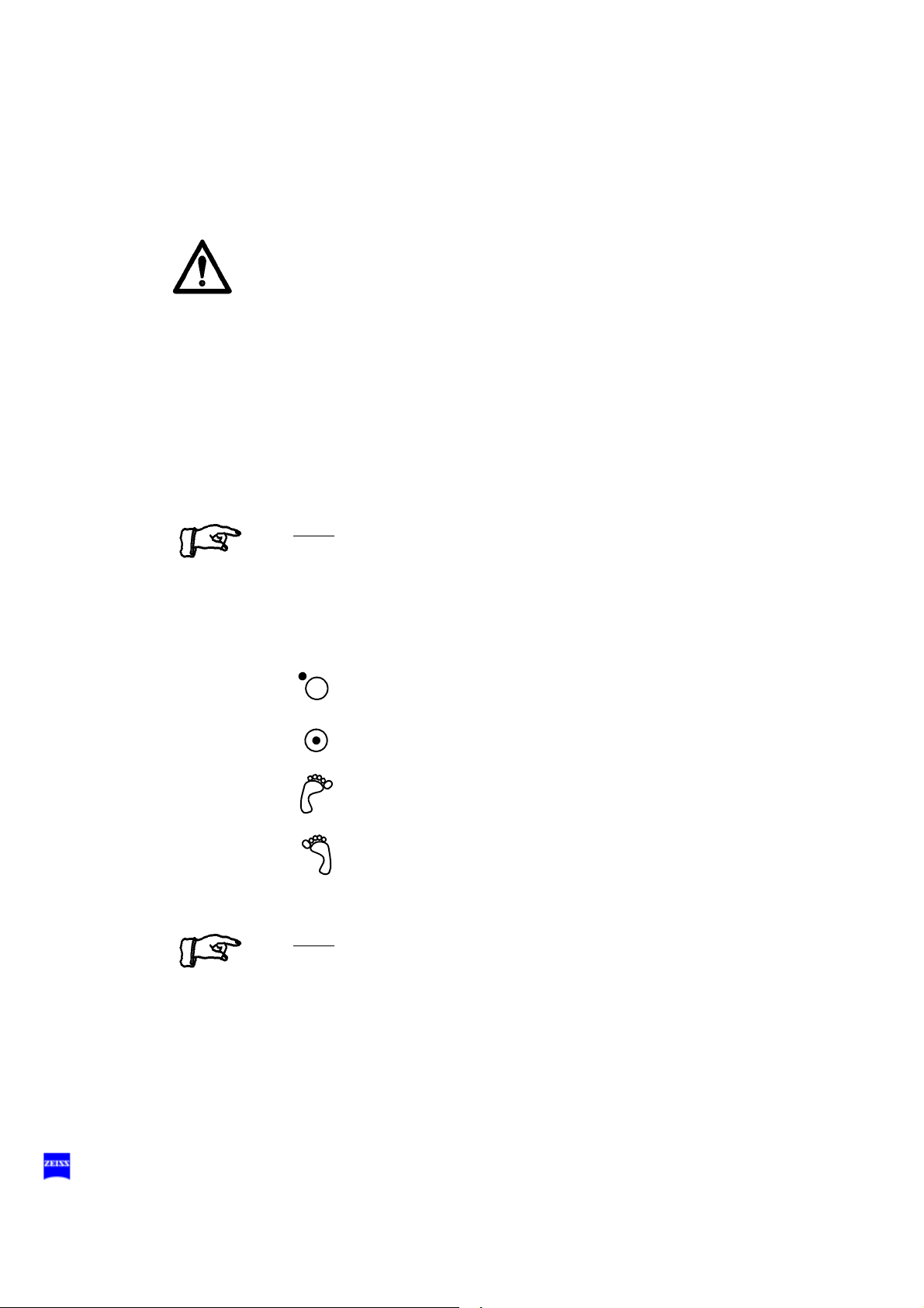
90 Description
8 Brightness control
You can adjust the brightness using the two control keys on the control
panel. The brightness of the xenon lamp can also be adjusted by
pressing the appropriate buttons on the foot control panel.
Warning!
Too much light intensity (brightness setting is too high) or excessive radiation exposure times may lead to retinal injury in the patient's eye.
• Adjust the illumination intensity as required for the selected type of il-
lumination and the radiation exposure time. You will find the values
recommended by Carl Zeiss in the table "Maximum radiation exposure times" on page 29.
9 Yellow indicator lamp
Lights when the lamp has failed, or if the lamp module is defective.
After activation and ignition of the backup lamp, the yellow indicator
lamp goes out again.
Note:
If the first lamp has failed and the backup lamp is in use, make sure to
have a backup lamp module ready at hand as a precaution.
10 Green indicator lamp
Lights when the light source has been switched on.
11 Selector:
The light source is off.
The light source is on.
The light source can be switched on/off on the left-hand side
of the foot control panel.
The light source can be switched on/off on the right-hand
side of the foot control panel.
Note:
You can adjust the selector in such a way that you can switch the light
source on/off on the right-hand and left-hand sides of the foot control
panel.
G-30-1682-en OPMI® Lumera® T Issue 4.0
Printed on 02. 02. 2009
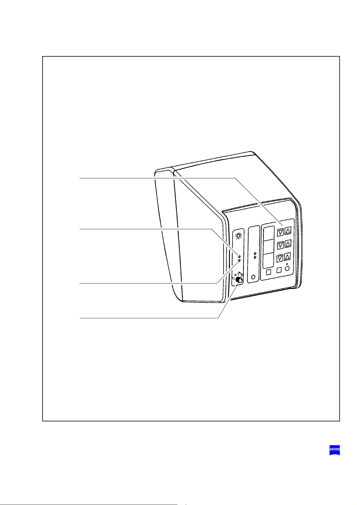
Description 91
8
11
9
10
G-30-1682-en OPMI® Lumera® T Issue 4.0
Printed on 02. 02. 2009

92 Description
Superlux Eye with integrated halogen light source (option)
Warning!
The xenon lamp has a limited service life of 500 h.
If used beyond its maximum service life, the xenon lamp may explode.
• Replace the xenon lamp in good time.
• Reset the service hour counter to "0" after replacing the lamp.
Please observe the procedure described on page 80.
Superlux Eye with an integrated halogen light source is a combination of
the two light sources described above. Like the Superlux Eye light source,
this combination is also available with two filter versions: the HaMode filter
and the 485 mm fluorescence excitation filter.
Ventilation grid
Do not cover the ventilation grid! For example, drapes could be covering
the grid. This can lead to overheating of the lamp modules and to lamp
failure.
1 Filter selector knob
The filter selector knob has the following positions:
no filter
blue barrier filter (retina protection filter)
HaMode filter (standard)
485 nm fluorescence excitation filter (option)
2 Counter
The counter records the service hours of the xenon light source.
Change the xenon lamps after about 500 hours of operation to avoid
any explosion of the xenon lamps, and reset the counter to "0". Use a
pointed object and press it into the recess of reset button (3).
3 Reset button
The reset button resets the service hour counter to "0".
4 Opening the Superlux Eye lamp module
G-30-1682-en OPMI® Lumera® T Issue 4.0
Printed on 02. 02. 2009

Description 93
241 53
When you press this button, the lamp module is slightly ejected. For
changing the lamp, pull out the lamp module as far as it will go. Turn
knob (5) through 180° until it snaps in. This moves the backup lamp
into the illumination beam path.
5 Manual activation of the Superlux Eye backup lamp
When the xenon lamp fails, open the lamp module as follows:
Press button (4). The lamp module is slightly ejected. Pull out the lamp
module as far as it will go. Turn knob (5) through 180° until it snaps in.
This moves the backup lamp into the illumination beam path. Push the
lamp module all the way back into the lamp housing. Use a pointed object and press it into the recess of reset button (3).
Note:
When inserting a new lamp module, make sure that knob (2) is set to
"1“. If the first lamp fails, you switch to the second lamp in logical sequence.
G-30-1682-en OPMI® Lumera® T Issue 4.0
Printed on 02. 02. 2009
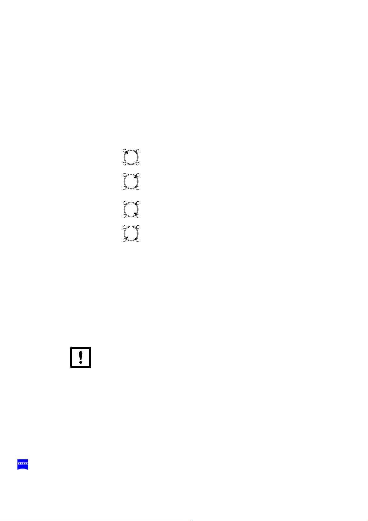
94 Description
6 Flap
The flap is the mechanical indicator for the operating status of the halogen lamps.
– When the flap is closed, the main lamp is operative (green light
(15) is on).
– When the flap is open, the main lamp has failed. The backup lamp
is used (yellow light (14) is on).
7 Filter selector knob for the additional integrated halogen light source
The filter knob has four positions:
no filter
blue barrier filter (retina protection filter): when operating on
the eye, always use this filter to protect the patient's eye
against unnecessary radiation (retinal injury).
KK 40 filter:
to increase the color temperature
empty filter position
8 Opening the lamp module of the additional integrated halogen light
source
When you press this button, the lamp module is slightly ejected. Pull
out the lamp module all the way for lamp change.
9 Manual activation of the halogen backup lamp
If the automatic activation system fails, press this button to switch on
the backup lamp.
10 Indicator: Superlux Eye backup lamp is in use
When the red segment in the knob lights up, the backup lamp is in use.
11 Ventilation grid for the additional integrated halogen light source
Do not cover the ventilation grid! For example, drapes could be covering the grid. This can lead to overheating of the lamp modules and
to lamp failure.
12 Lamp module of the additional integrated halogen light source
13 Superlux Eye lamp module
G-30-1682-en OPMI® Lumera® T Issue 4.0
Printed on 02. 02. 2009

Description 95
67 8910
111213
14
15
H
a
l
o
g
e
n
X
e
n
o
n
G-30-1682-en OPMI® Lumera® T Issue 4.0
Printed on 02. 02. 2009
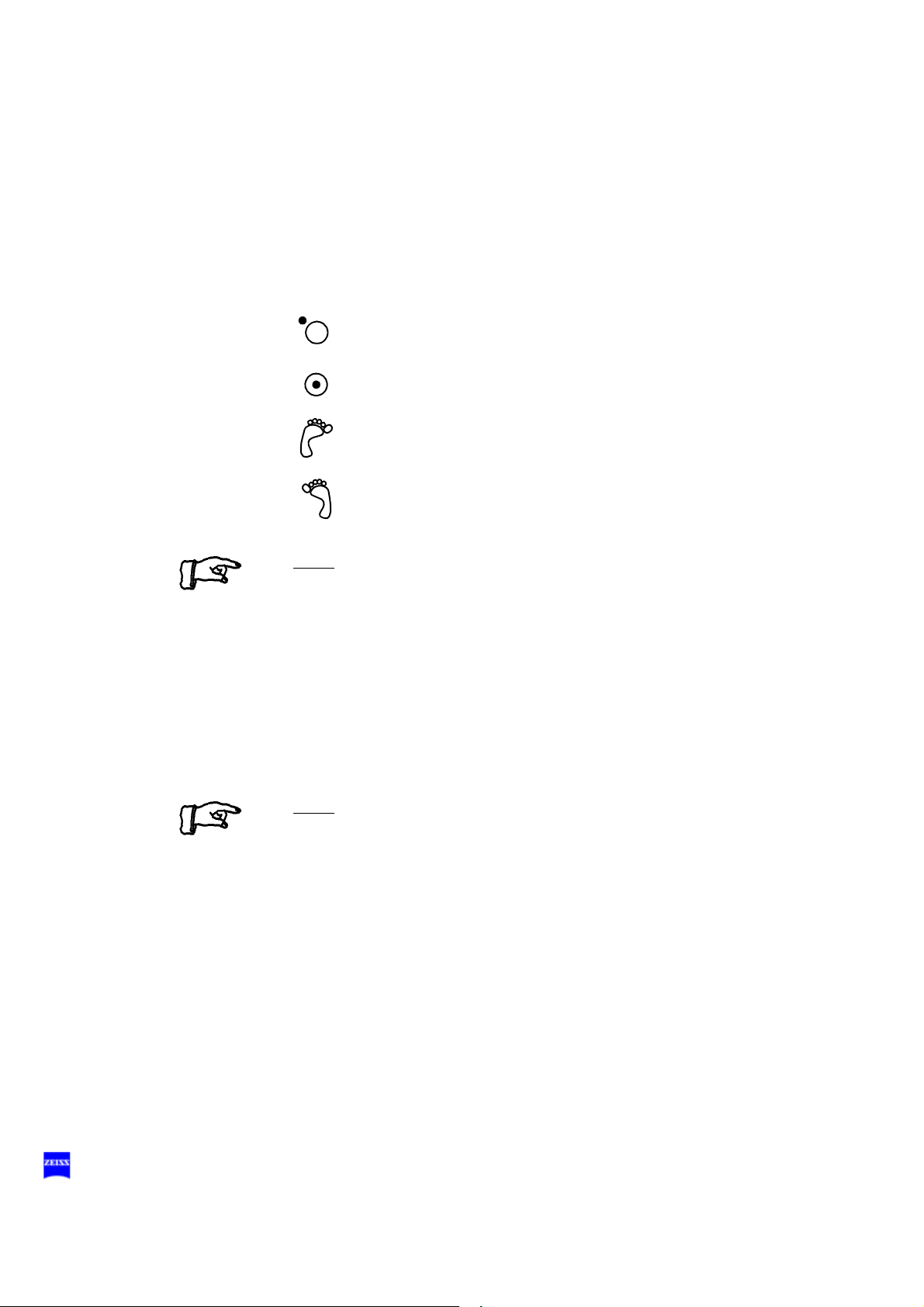
96 Description
14 Yellow indicator lamp
– Lights when the main lamp has failed. The backup lamp is on.
– Blinks when the backup lamp has failed.
15 Green indicator lamp
Lights when the respective light source has been switched on.
16 Selector:
The light source is off.
The light source is on.
The light source can be switched on/off on the left-hand side
of the foot control panel.
The light source can be switched on/off on the right-hand
side of the foot control panel.
Note:
If two lamp housings are available, you can set the selector switch in
such a way
– that one light source each can be switched on/off on the left-hand
and right-hand side of the foot control panel,
– or that both light sources can be switched on/off on the left-hand
or right-hand side of the foot control panel.
17 Brightness control
You can adjust the brightness using the two control keys on the control
panel.
Note:
If the suspension system has two lamp housings, you can also adjust
the brightness of lamp 1 by pressing the appropriate button on the foot
control panel.
G-30-1682-en OPMI® Lumera® T Issue 4.0
Printed on 02. 02. 2009
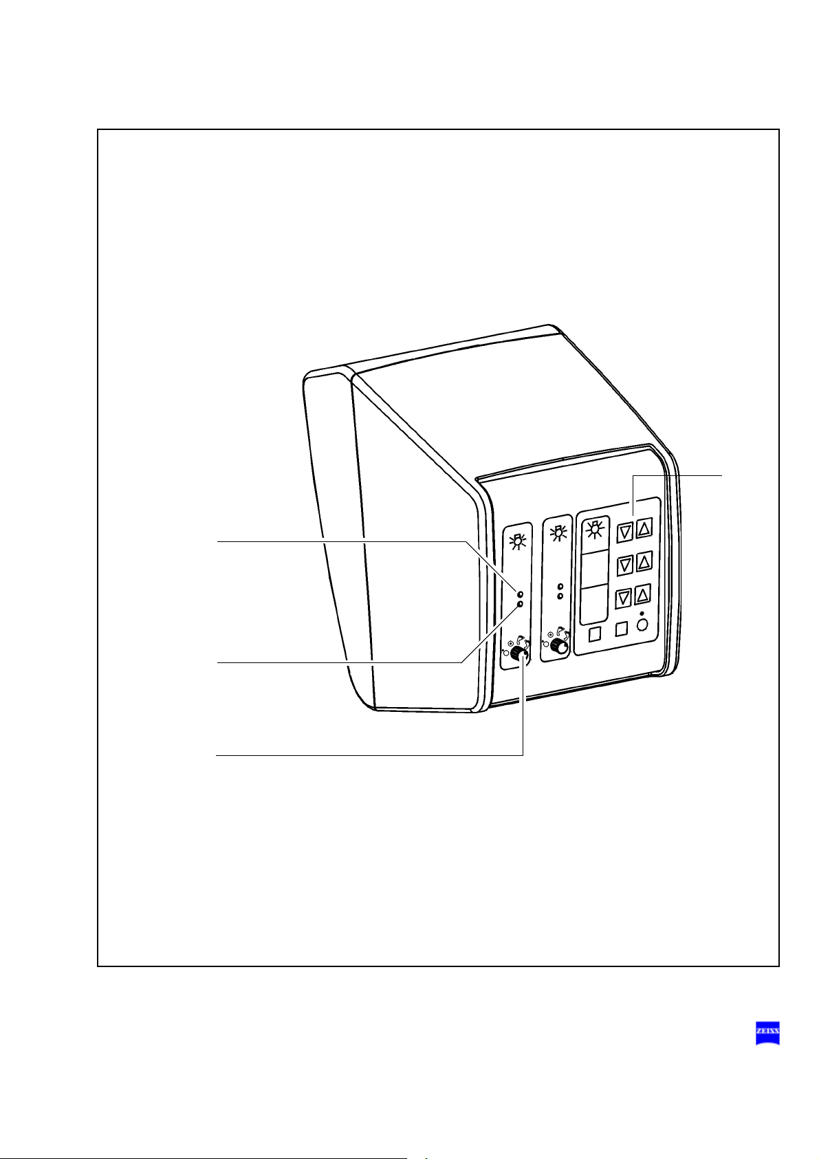
Description 97
17
15
14
16
0
,
7
H
a
l
o
g
e
n
X
e
n
o
n
G-30-1682-en OPMI® Lumera® T Issue 4.0
Printed on 02. 02. 2009

98 Description
Identical components of the suspension systems
Suspension arm
1 Lock of the cable duct
– For opening, turn a quarter turn clockwise or counterclockwise.
– For closing, press down and turn a quarter turn clockwise or coun-
terclockwise.
2 Adjustment screw for limiting downward movement
Use this screw to set the minimum vertical working distance from the
surgical field. Bring the surgical microscope into its working position.
Turn the adjustment screw for limiting downward movement clockwise
as far as it will go. Adjust the downward movement limitation before
each surgical procedure.
3 Balance setting screw
After mounting the surgical microscope including all
just the balance setting of the suspension arm using this screw. Balance setting is described in detail in chapter “Operation“.
4 Securing screw
for securing the OPMI
5 Locking knob
for locking the suspension arm in a horizontal position for mounting
the surgical microscope. This prevents the suspension arm from uncontrollably moving upward when insufficient weight is attached.
6 Release bar
Allows non-sterile persons to release the magnetic brakes of the suspension system.
Magnetic brake release buttons
The magnetic brake release buttons are located on the surgical microscope. For as long as you press one of these buttons, you can move the
articulated arm in all directions. When you let go of the button, the magnetic brakes will lock all axes in position at the same time.
®
coupling.
accessories, ad-
G-30-1682-en OPMI® Lumera® T Issue 4.0
Printed on 02. 02. 2009
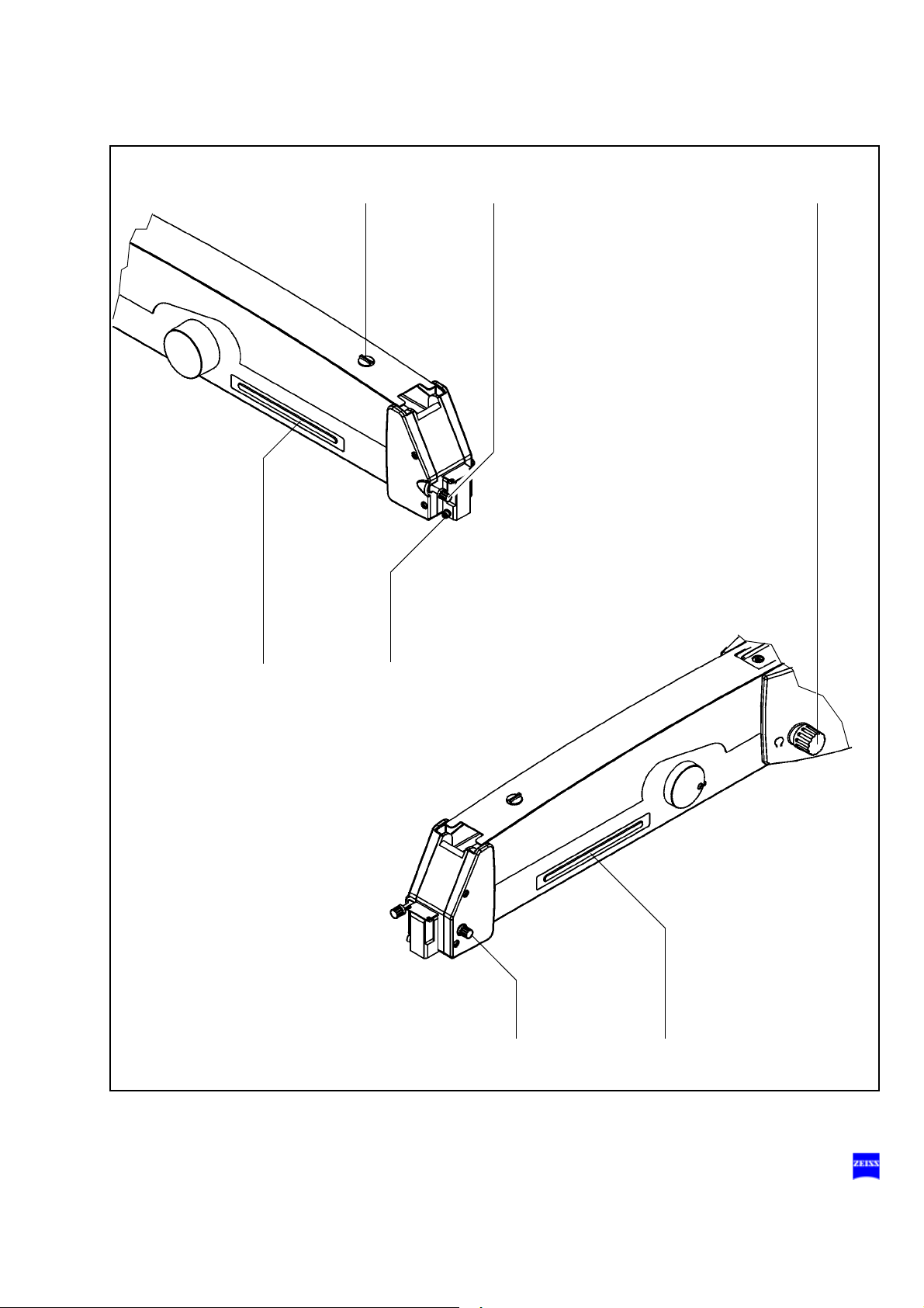
Description 99
12
5
3
4
6
6
G-30-1682-en OPMI® Lumera® T Issue 4.0
Printed on 02. 02. 2009
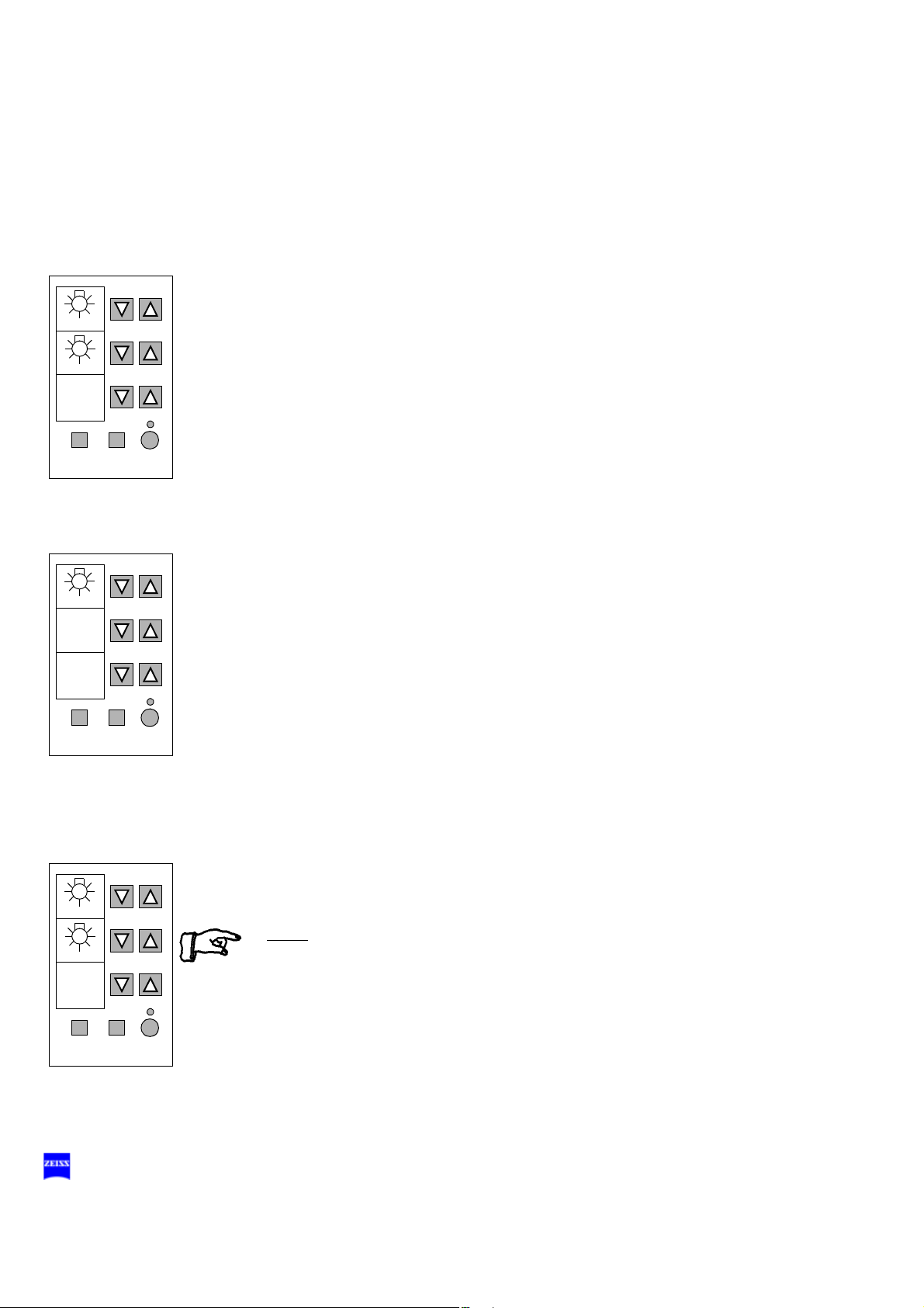
100 Description
MODE
STORE MANUAL
USER
1
1
1,5
Basic mode
Halogen
MODE
STORE MANUAL
USER
1
1
1,5
2
1,5
Xe
Xenon
Xenon with hal-
ogen (option)
MODE
STORE MANUAL
USER
1
1
1.5
2
1.5
Display field with control keys
The display and control panel is integrated in the control unit.
The surgical microscope on the suspension system can be controlled either manually or electronically. The control software required for electronic control is installed in the electronics box of the suspension system.
You operate the software via the control and display panel, where you can
read off and reconfigure the current settings.
The control and display panel is structured as follows:
– Three display fields (LCD) with the associated keys "∇" and "Δ".
One row of keys comprising the MODE, STORE and MANUAL keys, and
a yellow LED above the MANUAL key.
User interface
The user interface of the suspension system comprises three display
fields and keys located beside and below them.
A pair of keys "∇" and "Δ" has been assigned to every display field for
making the appropriate settings.
The control functions have been combined in several modes (menu
pages). The basic mode is always displayed in the normal operating
status.
The following is displayed in the basic mode:
– the current lamp brightness of lamp 1 (halogen) in the upper display
field,
– the current lamp brightness of lamp 2 (halogen) in the middle display
field,
– the current lamp brightness of lamp 1 (xenon) in the upper display
field,
– Xe for xenon in the middle display field,
– the current user ID in the lower display field.
Note:
For the Superlux Eye light source with additional, integrated halogen illumination (option), the lamps are numbered as follows:
Lamp 1: xenon
Lamp 2: halogen
G-30-1682-en OPMI® Lumera® T Issue 4.0
Printed on 02. 02. 2009
 Loading...