


YHC5150X
YHC5150X FieldMate Handheld Communicator
User’s Manual
IM 01R01A30-01EN-B
January, 2014 V 1.3
Safety Information
Failure to follow all instructions could result i n i njury. Read, understand and follow all
safety warnings and instructions provided with t hi s product. Also, meet or exceed your
employer’s safety practices.
In no event shall Yokogawa be liable for any indirect, special, incidental, con sequential or punitive
damages or for any lost profits arising out of or relating to any services provided by Yokogawa or its
affiliates. It is not possible for Yokogawa to identify all foreseeable uses/misuses, therefore all persons
involved in commissioning, using or maintai ning this product must satisfy their self that each intended
application is acceptable.
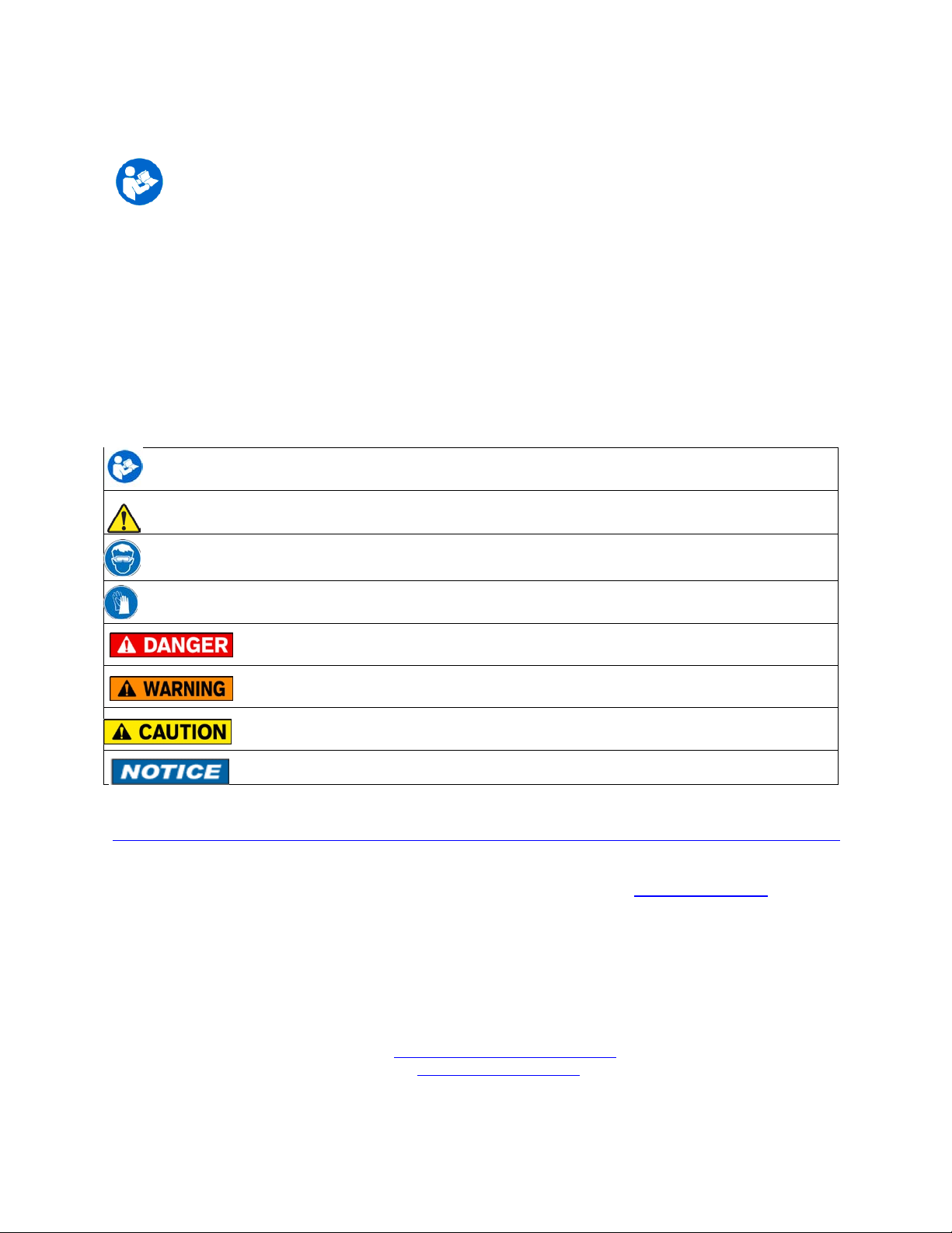
Safety Warnings
The table below defines the safety symbols, signal word s and corresponding safety messages used in the
manual to identify potential hazards and are intended to warn persons about hazards that could result in
personal injury or equipment damage.
This is the Read Instruction Manual symbol. T hi s symbol indicates
that you must read the instruction manual.
This is the Safety Alert symbol. T his symbol indicates a WARNING. Warnings alert you to actions that can
cause personal injury or pose a physical threat. Please read these carefully.
This is the Safety Glasses symbol. This symbol indicates that you must wear appr oved safety glasses during
the task.
This is the Safety Gloves symbol. Thi s symbol indicates that you must wear approved safety gloves during
the task.
Indicates a potentially hazardous situation which, if not avoided, will result in death or serious
injury.
Indicates a potentially hazardous situation which, if not avoided, could result in death or
serious injury.
Indicates a potentially hazardous situation which, if not avoided, could result in minor or
moderate injury.
Indicates information essenti al for proper product installation, operation or maintenance.
Information in this document is subject to change without notice. Check the Yokogawa web site:
http://www.yokogawa.com/us/products/field-instruments/ia-smart-communicators/yhc5150x.htm
for latest manual revision.
HART
®
is a registered trademark of the HART Communicat ion Foundation www.hartcomm.org
For customer assistance please call your local Yokogawa representative or Yokogawa directly.
Yokogawa Corporation of America
2 Dart Road
Newnan, GA. 30265
1-800-888-6400
E-mail: meters-instr@us.yokogawa.com
Web: www.yokogawa.com/us
ATEX DOCUMENTATION
applies only to European Union countries.
GB
DK
I
E
NL
SF
P
F
D
SK
CZ
LT
LV
EST
PL
SLO
H
BG
S
GR
RO
M

YHC5150X FieldMate Handheld Communicator
USER’S MANUAL
TABLE OF CONTENTS
Subject Page
YHC5150X Series Communicator Overview ............................................................................................ 1
Touchscreen Display Overview .......................................................................................................... 2
Display Layout ............................................................................................................................... 2
Keypad Layout ................................................................................................................................ 4
General Operation ..................................................................................................................................... 5
Power Button ....................................................................................................................................... 5
Backlight ............................................................................................................................................. 5
Display Auto Dim Timer .................................................................................................................... 5
Auto Standby Timer ............................................................................................................................ 5
Portable Operation / Battery Life ........................................................................................................ 5
PC Communication / Recharging Cradle ............................................................................................ 6
Battery Pack Installation & Removal ................................................................................................. 7
Memory Card ..................................................................................................................................... 8
Kick Stand ........................................................................................................................................... 8
External Connections ......................................................................................................................... 9
Keyboard Functionality .................................................................................................................... 10
Touch Keyboard Functionality ......................................................................................................... 12
Navigating the communicator .................................................................................................................. 14
System Menus ................................................................................................................................... 14
General ........................................................................................................................................ 14
Main ............................................................................................................................................ 17
System Setup .............................................................................................................................. 18
Language .............................................................................................................................. 19
Touch Screen Calibration ..................................................................................................... 19
Date And Time Setup ................................................................................................................. 20
Power Management .................................................................................................................... 21
HART
®
Setup ............................................................................................................................. 22
System Information .................................................................................................................... 23
HART
®
Menu .................................................................................................................................... 24
HART
®
Navigation Menu ........................................................................................................... 25
Function Buttons ......................................................................................................................... 26
HART
®
Menu Path ..................................................................................................................... 28
HART
®
Communication with the YHC5150X Communicator ............................................................... 28
Overview ........................................................................................................................................... 28
HART
®
Connections ......................................................................................................................... 29
HART
®
Communication ................................................................................................................... 30
Device Specific & Generic HART
®
Communication ........................................................................ 31
Using Generic HART
®
Communications ........................................................................................... 32
Managing Device Configuration Files .............................................................................................. 32
Communication Troubleshooting ...................................................................................................... 33

Updating Software ................................................................................................................................... 34
Hazardous Area Use ................................................................................................................................ 34
Intrinsically Safe Operation ............................................................................................................... 34
Returning for Repair ................................................................................................................................ 36
APPENDIX
Product Specifications ........................................................................................................................ 37
Safety Notices .................................................................................................................................... 38
Waste Electrical and Electronic Equipment (WEEE), Directive 2002/96/EC ................................... 38
Spare Parts List ................................................................................................................................... 39
Intrinsic Safety Control Drawing ....................................................................................................... 40
1
1.0 YHC5150X Series HART
®
COMMUNICATOR OVERVIEW
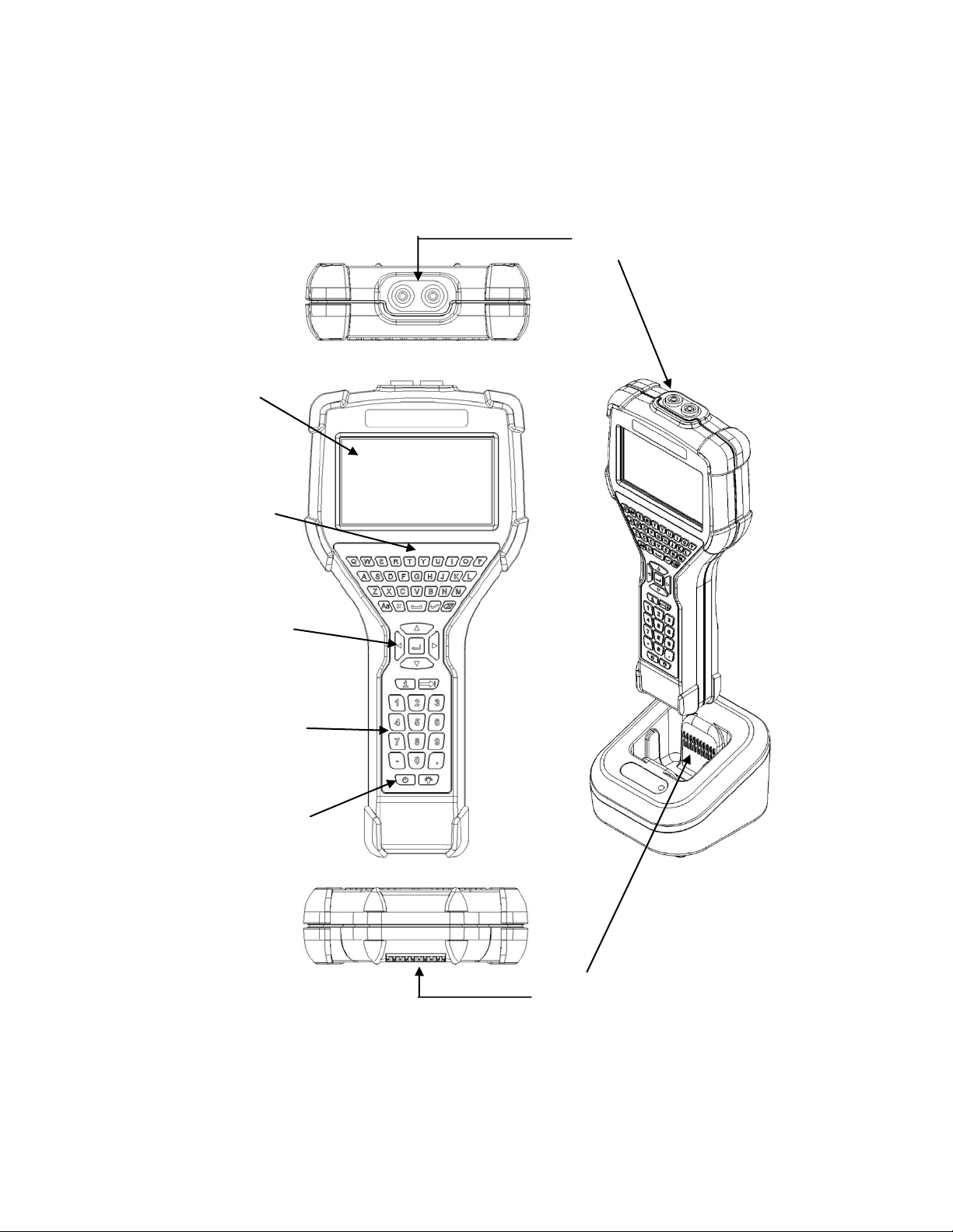
The YHC5150X Series HART
®
Communicator is a full function HART
®
Communicator supporting
HART
®
communication Universal, Common Practice and Device Specific commands for commissioning,
configuration and maintenance operations.
Charging Cradle
Connections
Display and
Touchscreen
Full QWERTY
style alphabetic
Keyboard
Navigation Keys
HART
®
Connections
Dedicated Numeric
Keypad
On/Off Key
2
1.1 TOUCHSCREEN DISPLAY OVERVIEW
The communicator has a 4.3-inch widescreen backlit TFT color touchscreen display with 480 x 272
WQVGA pixel resolution. The entire vi ewable area of the screen is an active touch surface. The touchscreen
responds to and is optimized for finger presses ( even through gloves). NO stylus is necessary. Never touch
the screen with sharp objects – simply use your finger.
Display Layouts
There are two styles of displays presented on the communicator, system menu displays (Section 3.1) and
HART
®
menu displays (Section 3.2).
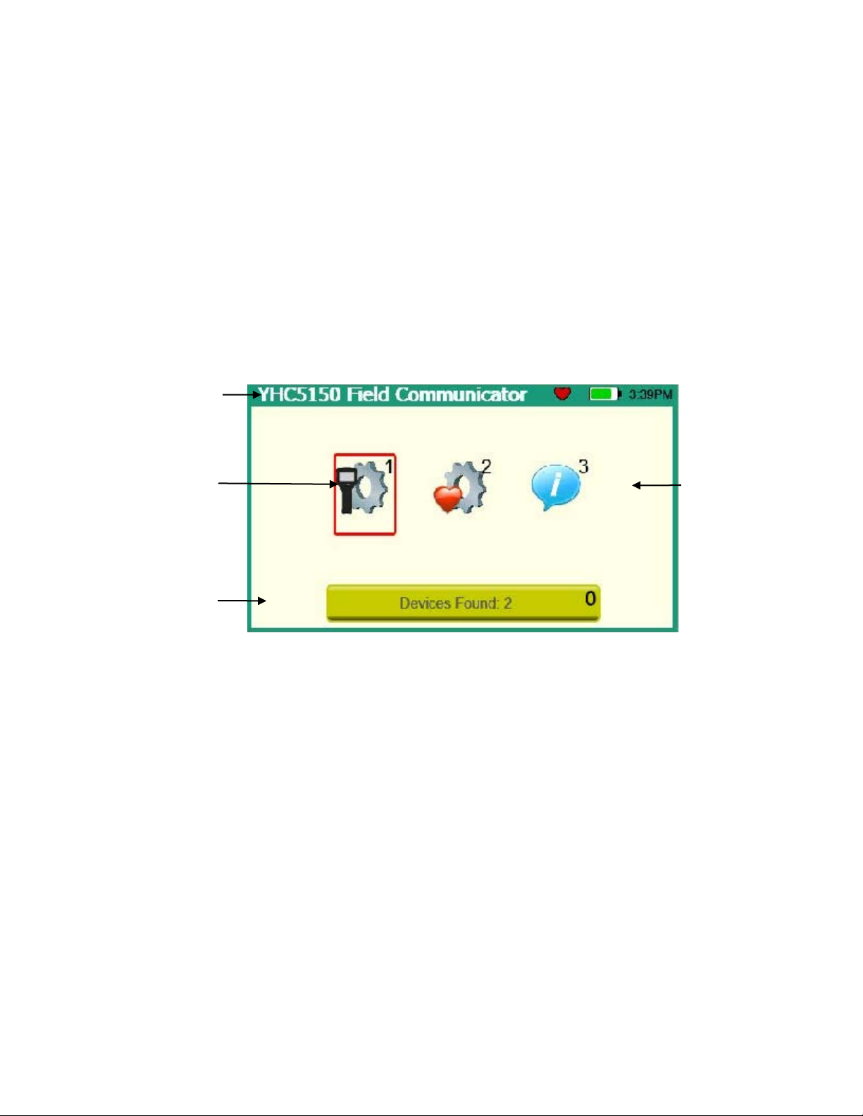
The main system menu display is the initial menu at power turn on. It is also accessible from any HART
®
menu (see Function Buttons in section 3.2). There are three distinct areas on the system menus. The top of
the menu provides system information. The middle of the menu contains navigation icons to system actions
or new system menus. The bottom of the menu contains current HART
®
connection status and navigation
buttons.
Sample system display
System
Information
HART
®
Connections
and
Navigation
System
Navigation
Focus Pane
3
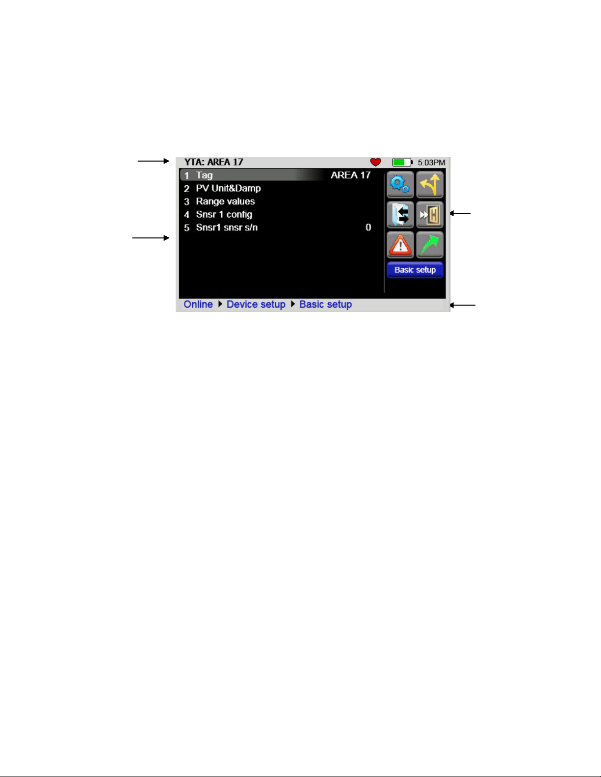
The HART
®
menus are only accessible when a HART
®
communication enabled device is connected and
communicating with the communicator. There are four distinct areas on a HART
®
menu. The top of the
menu provides information on the currently attached device as well as various status indicators. The middle
of the menu is divided into two functional areas, HART
®
Menu Navigation and Function Buttons. The
bottom of the menu contains the HART
®
Menu Path.
Function
Buttons
Device and
Status Line
HART
®
Navigation
HART
®
Menu
Path
Sample HART
®
menu display
4
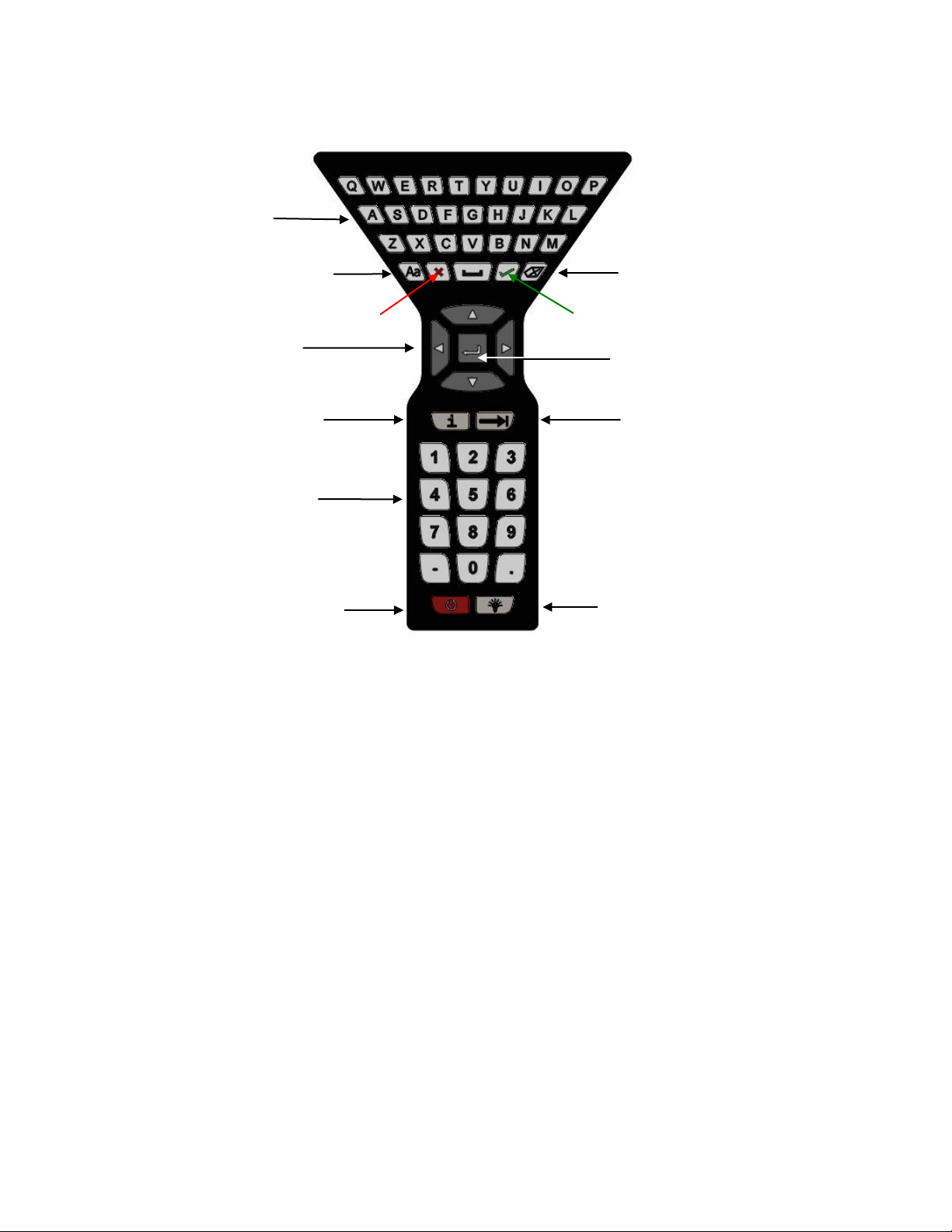
1.2 Keyboard Layout
The communicator provides a high functionality keyboard, combined with touch screen data k eys, to
simplify data entry and navigation. Most tasks can be completed by just using the dedicated keyboard. The
touch screen keys (only visible during text data entry) add the complete ISO Latin-1 (ISO 8859-1) character
set, except numerals, in a large, easy to select key size.
Alpha Entry
Upper/Lower case Toggle
Cancel
Backspace
OK or Accept
Advance or Switch
(to next functional
area on screen)
Navigation Ring
Enter or Select
Numeric Entry
(and Menu Accelerators)
Power
(Section 2.1)
Backlight
(Section 2.2)
Information
or Help

5
2.0 GENERAL OPERATION
2.1 Power Button
The Power Button has two functions:
Power On – Whenever the communicato r is in an “Off” state, pressing the power key turns the
communicator on. This is a complete system start. The communicator will execute a complet e power op
sequence. Information regarding the time and date is briefly displayed to allow the user to verify the
communicator’s readiness
.
Standby Operation – When the communicator is fully on, and the power button is pressed briefly, the unit
enters the Standby state where allowed. In this state the display is off and most user input is ignored to
conserve battery power between uses. The on-board computer maintains the previous system state to
provided rapid recovery (Resume Operation).
Resume Operation - When the communicator is in Standby Operation, and the power button is pressed
briefly, the unit quickly resumes operation, returning to a fully “On” state of functional ity at the same menu
level that was interrupted.
Power Off – When the communicator is fully on, and the power button is pressed for three seconds, the unit
will power down completely where allowed. This conserves the most battery power but r equires a full
initialization when the unit is turned on again.
2.2 Backlight
The Backlight has 5 intensities from mini mum to full Brigh tness. The user can select intensities by pressing
the Backlight Button. Backlight intensity affects battery life. A lower intensity level will increase operation
time.
2.3 Display Auto Dim Timer
Display Auto Dim is a configurab le mode that allows the user to minimize the backlight when there is no
user or HART
®
activity detected by the communicator for a user defined period of time. This period is
adjustable using the Display Auto Dim Timer. A shorter period will decrease battery consumption when the
communicator is not being used.
2.4 Auto Standby Timer
Auto Standby is a configurable mode that allows the user to automatically put the communicator into a
standby state when there is no user or
HART
®
activity detected by the communicator for a user defined
period of time. The inactivity period is adjustable using the Auto Standby timer. In combination with the
Display Auto Dim Timer, shorter period wil l decrease battery consumption. The standby timeout begins
when the Auto Dim Timer times out. If the Auto Dim Timer is set to “Never” the standby timeout will not
begin.
2.5 Portable Operation / Battery Life
The communicator is powered by a rechargeable li-ion battery pack for portable operation. A full charge
typically allows for 20 hours of typical operation. See section 2.7 for instruction on battery removal and
replacement. Replacement battery packs are available from Yokogawa (1W-9A820-1).
6
The battery pack contains an advanced b attery fuel gauge that actively monitors the battery capacity and
therefore does not require any “battery training” throughout the life of the battery pack.
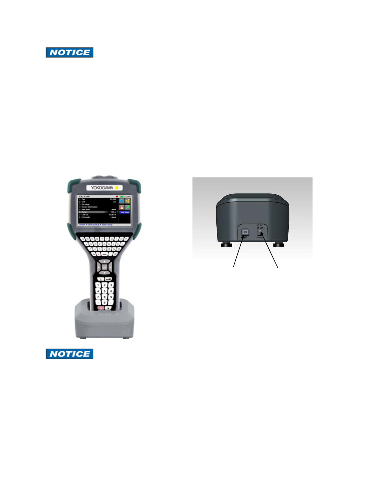
2.6 PC Communication / Recharging Cradle
The Recharging Cradle, included with each unit, automatically recharges the l i-ion battery pack when the
communicator i s properly inserted into the energized cradle. To fully charge a depleted battery pack takes
about four and one half hours.
The recharging cradle also connects the communicator with a PC for file updates to the communicator when
it is properly inserted in the cradle and a USB cable is attached from the cradle to a PC with the proper USB
drivers and Yokogawa update package. See section 5 for update instructions.
The Recharging Cradle is not intended to recharge a battery separately. To properly charge a battery
pack it is required to be inserted into a communicator prior to being placed on the charger.
Charging Indicator
There is a multicolor LED on the recharging cradle. This LED indicates the current charging mode.
Off – No battery pack inserted, or power disconnected.
Solid Green – Battery is charged.
Flashing Amber – Battery is charging.
Solid Amber – Battery temperature out of charging range (10°C-40°C), charge suspended.
Flashing Red – Battery fault.
Solid Red –Charger fault.
USB connection
to computer
Power jack for
AC adapter
Cradle Connection Details
YHC5150X in charging cradle
Rear of cradle
7
The Recharging Cradle is not rated for intrinsic safety and should only be used in a non-hazardous area.
See the “Hazardous Area Use” section of this manual and the Intrinsic Safety Control Drawing in the
Appendix of this manual for more information.
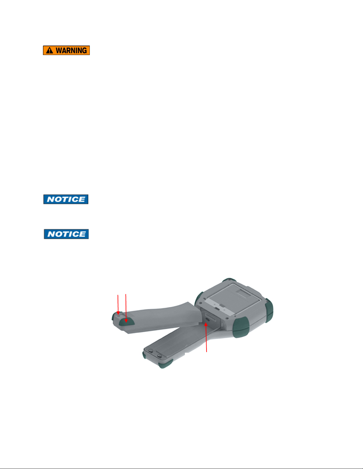
2.7 Battery Pack Installation & Removal
The battery pack is held into the communicator by two standard 6-32 screws with hexagonal sockets that
require a 7/64” hex key wrench.
To install the battery pack set the communicator enclosure with the display downward on a flat stable
surface. Rest the battery pack in the battery pack compartment of the enclosure leaving a ½” gap between
the battery pack and the connector on the communicator enclosure. Slide the battery pack upward along the
enclosure until the connectors mate completely and the screws are aligned with the threaded inserts on the
communicator body. Thread the screws into the insert to complete the installation.
For disassembly, reverse the order of the operations.
Over-tightening the battery case screws when assembling can cause damage to the communicator.
Maximum torque should not exceed seven in-lb.
Battery should be charged completely (10 hours) before using the communicator the first time. See Section
2.9 for detail on using the charging cradle.
Battery pack removal
6-32 screws with
7/64” hexagonal socket
µSD memory
card access
8
2.7 Memory Card
The communicator is shipped standard with a µSD memory system card. The system card is used for storage
of required software, software updates, HART
®
DD files and device configuration f iles. It is not intended for
use unrelated to the operation of the communicator. When the µSD memory system card is in the
YHC5150X, the user has no access to the card except with the Yokogawa provided P C software.
This card should only be replaced by Yokogawa part 1W-9P780, or its successor, and only under the
direction of Yokogawa personnel. Use of a non-system memory card will void safety certifications.
To access the memory card, follow the Battery Pack removal instructions.
To remove the memory card - Once the battery pack has been removed, press gently on the memory card to
unlock it from the card holder. Carefully remove the memory card from the enclosure ( Note: tweezers or
small needle-nose pliers can be helpful in removal and insertion).
To replace the memory card – Insert the memory card carefully into the card holder, contacts toward the back
of the communicator and card label towards the front (scre en side) of the communicator. Be sure the
memory card is resting in the holder before releasing it. Gently press the card into the holder to lock it into
place. Replace the battery pack and secure it to the communicator enclosure.
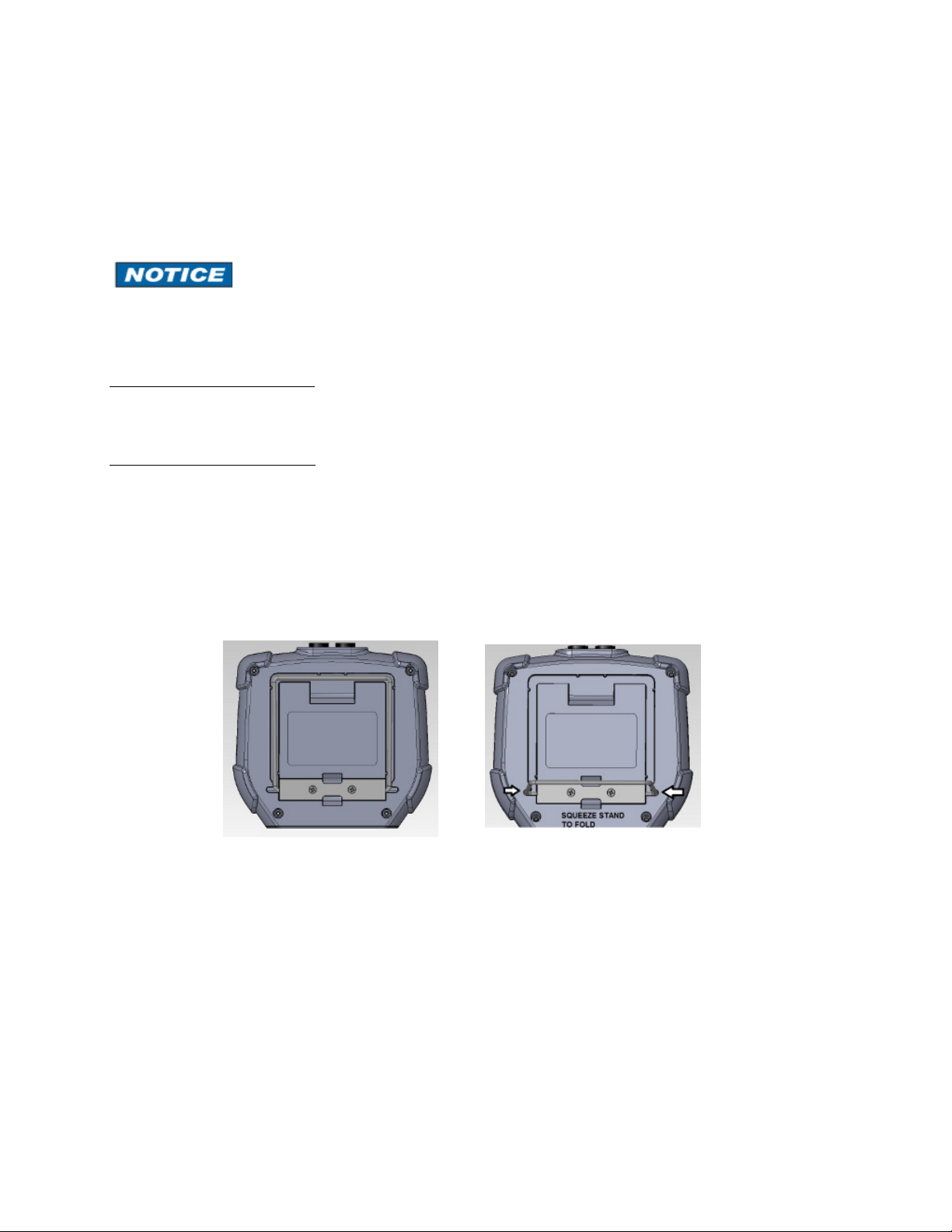
2.8 Kick Stand
The communicator is equipped with a kick stand to provide a better viewing angle. The stand latches in the
down/open position. To return the kick stand to the up/closed position squeeze the base inwards from both
sides to unlatch it.
 Loading...