


 Loading...
OWNER’S SERVICE MANUAL
MANUEL D’ATELIER DU PROPRIETAIRE
FAHRERUND WARTUNGSHANDBUCH
TT-R90(V)
TT-R90E(V)
3P2-28199-80

EC010000
TT-R90(V)/TT-R90E(V)
OWNER’S SERVICE MANUAL ©2005 by Yamaha Motor Co., Ltd. 1st Edition, April 2005
All rights reserved. Any reprinting or unauthorized use without the written permission of Yamaha Motor Co., Ltd. is expressly prohibited.
Printed in Japan

TT-R90(V)/TT-R90E(V) |
|
TT-R90(V)/TT-R90E(V) |
MANUEL D’ATELIER |
|
FAHRERUND |
DU PROPRIETAIRE |
|
WARTUNGSHANDBUCH |
©2005 Yamaha Motor Co., Ltd. |
|
©2005 Yamaha Motor Co., Ltd. |
1re édition, avril 2005 |
|
1. Auflage, April 2005 |
Tous droits réservés |
|
Alle Rechte vorbehalten. |
Toute reimpression ou |
|
Nachdruck, Vervielfältigung und |
utillisation sans la permission |
|
Verbreitung, auch auszugsweise, ist |
écrite de la Yamaha Motor Co., Ltd. |
|
ohne schriftliche Genehmigung der |
est formellement interdite. |
|
Yamaha Motor Co., Ltd. nicht gestattet. |
Imprimé au Japon |
|
Gedruckt in Japan |
|
|
|
INTRODUCTION
Congratulations on your purchase of a Yamaha TT-R90/TT-R90E. This model is the culmination of Yamaha’s vast experience in the production of pacesetting racing machines. It represents the highest grade of craftsmanship and reliability that have made Yamaha a leader.
This manual explains operation, inspection, basic maintenance and tuning of your machine. If you have any questions about this manual or your machine, please contact your Yamaha dealer.
NOTE:
As improvements are made on this model, some data in this manual may become outdated. If you have any questions, please consult your Yamaha dealer.
 WARNING
•READ THIS MANUAL CAREFULLY FOR INSTRUCTIONS ON HOW TO PROPERLY OPERATE THIS MACHINE.
•ADULT INSTRUCTION AND SUPERVISION ARE REQUIRED.
•WEIGHT OF THE RIDER SHOULD NOT EXCEED 40 kg (88 lb).
•ALWAYS WEAR A HELMET AND SUITABLE PROTECTIVE CLOTHING WHEN RIDING.
•DO NOT TOUCH ANY MOVING PARTS OR HEATED AREAS.
•ALWAYS PERFORM PRE-OPERATION CHECKS. REFER TO PAGE 3-2.
•THIS MACHINE IS DESIGNED TO CARRY THE OPERATOR ONLY.
NO PASSENGERS.
•THIS MACHINE IS DESIGNED OFF-ROAD USE ONLY.
IT IS NOT SUITABLE FOR ON-ROAD USE.
INTRODUCTION |
EINFÜHRUNG |
Félicitations au propriétaire de la TT-R90/TT- R90E de Yamaha. Ce modèle représente le fruit de nombreuses années d’expérience dans la production de motos de course. Le nouveau propriétaire pourra apprécier pleinement la perfection technique et la fiabilité qui ont fait de Yamaha un leader dans ce domaine.
Ce manuel explique le fonctionnement, l’inspection, l’entretien de base et la mise au point de la moto. Pour toute question à propos de ce manuel ou de la moto, prière de prendre contact avec un concessionnaire Yamaha.
N.B.:
Comme des améliorations sont faites sur ce modèle, quelques données contenues dans ce manuel peuvent être périmées. Pour toute question, prière de consulter un concessionnaire Yamaha.
 AVERTISSEMENT
•LIRE ATTENTIVEMENT CE MANUEL DANS SON INTEGRALITE AVANT D’UTILISER LA MOTO.
•INSTRUCTION ET SUPERVISION PAR UN ADULTE REQUIS.
•LE POIDS DU PILOTE NE PEUT PAS EXCEDER 40 kg (88 lb).
•TOUJOURS PORTER UN CASQUE ET DES VETEMENTS DE PROTECTION ADEQUATS POUR CONDUIRE.
•NE PAS TOUCHER LES PIECES MOBILES OU LES SURFACES CHAUDES.
•TOUJOURS EFFECTUER LES CONTROLES AVANT L’UTILISATION. SE REPORTER A LA PAGE 3-2.
•CETTE MOTO EST CONCUE POUR LE TRANSPORT D’UNE PERSONNE UNIQUEMENT.
LES PASSAGERS NE SONT PAS ADMIS.
•CETTE MOTO EST CONCUE POUR UNE UTILISATION TOUT TERRAIN UNIQUEMENT.
ELLE NE CONVIENT PAS A LA CONDUITE SUR ROUTE.
Herzlich willkommen im Kreis der TT-R90/TT- R90E-Fahrer. Dieses Modell wurde mit jahrzehntelanger Erfahrung sowie neuester Yamaha-Technologie entwickelt und gebaut. Daraus resultiert ein hohes Maß an Qualität und die sprichwörtliche Yamaha-Zuverlässigkeit.
In dieser Anleitung erfahren Sie, wie Sie Ihr Motorrad am besten bedienen, inspizieren, warten und abstimmen. Sollten Sie darüber hinaus noch weitere Fragen haben, wenden Sie sich bitte an den nächsten Yamaha-Händ- ler Ihres Vertrauens.
HINWEIS:
Aufgrund der kontinuierlichen Bemühungen von Yamaha um technischen Fortschritt können einige Angaben in dieser Anleitung für Ihr Modell nicht zutreffen. Richten Sie Fragen zu dieser Anleitung bitte an Ihren Yamaha-Händler.
 WARNUNG
•DIESE ANLEITUNG MUSS VOR DER INBETRIEBNAHME SORGFÄLTIG STUDIERT WERDEN, UM EINE SICHERE VERWENDUNG DES FAHRZEUGS ZU GEWÄHRLEISTEN.
•DIE ANWESENHEIT VON ERWACHSENEN IST BEI DER INBETRIEBNAHME DES FAHRZEUGS UNBEDINGT ERFORDERLICH.
•DAS FAHRERGEWICHT SOLLTE 40 kg (88 lb) NICHT ÜBERSCHREITEN.
•BEIM FAHREN IMMER EINEN HELM UND ENTSPRECHENDE SCHUTZKLEIDUNG TRAGEN.
•SICH BEWEGENDE UND HEISSE TEILE NICHT BERÜHREN.
•VOR FAHRTANTRITT STETS DIE ROUTINEKONTROLLE DURCHFÜHREN. SIEHE DAZU S. 3-2.
•DIESES FAHRZEUG IST NUR FÜR EINE PERSON ZUGELASSEN.
PASSAGIERE SIND NICHT GESTATTET.
•DIESES FAHRZEUG IST AUSSCHLIESSLICH FÜR DEN EINSATZ IM GELÄNDE VORGESEHEN.
DER GEBRAUCH AUF ÖFFENTLICHEN STRASSEN IST NICHT ZULÄSSIG.
IMPORTANT NOTICE
This machine is designed for off-road use only by young operators under adult instruction and supervision. It is illegal for this machine to be operated on any public street, road, or highway.
Off-road use on public lands may be illegal. Please check local regulations before riding.

 SAFETY INFORMATION
1.GASOLINE IS HIGHLY FLAMMABLE:
*Always turn off the engine when refueling.
*Take care not to spill on the engine or exhaust pipe/muffler, when refueling.
*Never refuel while smoking or in the vicinity of an open flame.
2.If you should swallow some gasoline or inhale a lot of gasoline vapor, or allow some gasoline to get in your eye(s), see your doctor immediately. If any gasoline spills on your skin or clothing, immediately wash it with soap and water, and change your clothes.
3.Always turn off the engine before leaving the machine unattended. When parking the machine, note the following:
*The engine and exhaust pipe(s)/ muffler(s) may be hot. Park the machine in a place where pedestrians or children are not likely to touch the machine.
*Do not park the machine on a slope or soft ground; the machine may overturn.
NOTE IMPORTANTE
Ce véhicule est conçu uniquement pour une utilisation tout-terrain par des pilotes très jeunes roulant sous la surveillance d’un adulte, après avoir reçu les instructions nécessaires par un adulte. L’utilisation de cette moto sur la voie publique (rue, route, autoroute, etc.) est interdite.
L’utilisation de cette moto sur des terrains publics peut être illégale. Avant utilisation, prendre connaissance des réglementations locales.

 INFORMATION DE SECURITE
1.L’ESSENCE EST UN PRODUIT TRES INFLAMMABLE:
*Toujours couper le moteur avant de faire le plein.
*Bien veiller à ne pas renverser d’essence sur le moteur ou le tuyau et pot d’échappement en faisant le plein.
*Ne pas faire le plein en fumant ou à proximité d’une flamme.
2.En cas d’ingestion d’essence, d’inhalation importante de vapeur d’essence ou d’éclaboussure dans les yeux, consulter immédiatement un médecin. En cas d’éclaboussure d’essence sur la peau ou les vêtements, se laver immédiatement à l’eau et au savon et changer de vêtements.
3.Toujours couper le moteur avant de laisser le véhicule sans surveillance. Au moment de se garer, être attentif aux points suivants:
*Le moteur ainsi que les éléments du système d’échappement risquent d’être brûlants. Garer le véhicule à un endroit où les piétons et particulièrement les enfants ne risquent pas de le toucher.
*Ne pas stationner dans une pente ou sur un sol meuble où la moto pourrait se renverser.
WICHTIGER HINWEIS
Dieses Motorrad ist ausschließlich für den Gebrauch abseits öffentlicher Straßen durch junge Fahrer unter Beaufsichtigung von erwachsenen Personen vorgesehen. Der Einsatz dieses Motorrads auf öffentlichen Straßen und Wegen oder Autobahnen ist nicht gestattet.
Der Einsatz auf öffentlichem Gelände kann verboten sein. Vor Fahrtantritt unbedingt die örtlichen Bestimmungen prüfen.

 SICHERHEITSINFORMATION
1.BENZIN IST LEICHT ENTZÜNDLICH, DAHER:
*Nur bei abgestelltem Motor tanken.
*Darauf achten, dass beim Tanken kein Kraftstoff auf Motor und Auspuffanlage verschüttet wird.
*Beim Tanken nicht rauchen und darauf achten, dass sich keine offenen Flammen in der Nähe befinden.
2.Falls Benzin geschluckt wurde, große Mengen Kraftstoffdampf eingeatmet wurden oder Kraftstoff in die Augen gelangt ist, muss unverzüglich ein Arzt aufgesucht werden. Falls Benzin auf Haut oder Kleidung gelangt, sofort mit Seifenlauge abwaschen und die Kleidung wechseln.
3.Den Motor stets abstellen, wenn das Fahrzeug unbeaufsichtigt ist. Beim Parken folgende Punkte beachten:
*Motor und Auspuffanlage werden sehr heiß. Deshalb so parken, dass Fußgänger und Kinder die heißen Teile nicht versehentlich berühren können.
*Das Motorrad nicht auf weichem oder abschüssigem Grund abstellen: es könnte umfallen.

4.When transporting the machine in another vehicle, be sure is kept upright and that the fuel cock is turned to the “OFF”. If it should lean over, gasoline may leak out of the carburetor or fuel tank.
5.Never start your engine or let it run for any length of time in a closed area. The exhaust fumes are poisonous and may cause loss of consciousness and death within a short time. Always operate your machine in an area with adequate ventilation.
6.Always wear a helmet, gloves, boots, trousers, and jacket for motocross riding.

4.Lors du transport de la moto dans un autre véhicule, veiller à le garder bien droit et à ce que le robinet de carburant soit sur “OFF”. Si le véhicule est incliné, l’essence risque de déborder du carburateur ou du réservoir.
5.Ne jamais mettre le moteur en marche ni le laisser tourner aussi peu de temps soit-il dans un local fermé. Les gaz d’échappement sont délétères et peuvent entraîner une perte de connaissance et même la mort en peu de temps. Ne laisser tourner le moteur que dans un endroit bien ventilé.
6.Pour faire du motocross, toujours porter un casque, des gants, des bottes, un pantalon et une veste de motard.
4.Für den Transport in einem anderen Fahrzeug das Motorrad aufrecht hinstellen und darauf achten, dass der Kraftstoffhahn auf “OFF”steht. Anderenfalls könnte Benzin aus dem Vergaser oder Kraftstofftank austreten.
5.Den Motor niemals in einem geschlossenen Raum anlassen oder betreiben. Motorabgase sind äußerst giftig und führen in kurzer Zeit zu Bewusstlosigkeit und Tod. Daher den Motor nur an einem gut belüfteten Ort betreiben.
6.Beim Fahren stets einen Helm und spezielle Motorradbekleidung (Handschuhe, Stiefel, Hose und Jacke) tragen.
 SAFETY INFORMATION
1. Don’t ride it on the street.
2. Don’t run the engine inside a building.
3.This is a one-seater motorbike. Don’t give any person a ride.
4.Let’s learn how to ride properly. Ask your parents for any question.
5. When riding the machine, be sure to wear the protective apparel as illustrated.
1Helmet
2Goggles
3Mouth guard
4Gloves
5Boots
6Motocross pants
7Long sleeved trainer
|
INFORMATION DE SECURITE |
|
SICHERHEITSINFORMATION |
|
1. Ne pas rouler sur la route. |
1. Betrieb auf öffentlicher Fahrbahn unter- |
|||
|
|
sagt. |
||
2. Ne pas faire tourner le moteur dans un bâti- |
2. Motor nicht in geschlossenen Räumen |
ment. |
betreiben. |
3.Il s’agit d’une moto à une seule place. Ne jamais transporter de passager.
4.Il est important d’apprendre à conduire correctement. Ne pas hésiter à poser des questions à un parent ou instructeur.
3.Dies ist ein Einpersonenfahrzeug. Beifahrer nicht zugelassen.
4.Sicheres Fahren muss erlernt werden. Im Zweifelsfall die Eltern fragen.
5. A moto, toujours porter un équipement de pro- |
5. Beim Fahren stets folgende Schutzklei- |
tection, comme illustré. |
dung tragen. |
1 Casque |
1 Helm |
2 Lunettes |
2 Augenschutz |
3 Protection pour la bouche |
3 Mundschutz |
4 Gants |
4 Handschuhe |
5 Bottes |
5 Stiefel |
6 Pantalons de motocross |
6 Motocross-Hose |
7 Veste à longues manches |
7 Langärmeliges Hemd |
6.When going for riding, be sure to be with your family.
Never go alone.
7.Before riding the machine, ask your parents to check the machine very carefully.
8.Don’t touch the areas shown, or you’ll get burnt in the hand.
9. Don’t touch rotating or moving parts.
10.Before starting the engine, be sure to shift the transmission into neutral.

6.Toujours partir à moto avec un parent ou instructeur.
Ne jamais partir seul.
7.Avant de rouler, demander à ce qu’un instructeur ait contrôlé attentivement la moto.
8.Ne jamais toucher les endroits indiqués, car ils peuvent être chauds. Il y a risque de brûlures.
9.Ne pas toucher les pièces mobiles ou qui tournent.
10.Avant de mettre le moteur en marche, bien veiller à être au point mort.
6.Niemals ohne Aufsicht der Eltern fahren. Niemals alleine fahren.
7.Vor der Fahrt das Motorrad sorgfältig von den Eltern prüfen lassen.
8.Die abgebildeten Teile nicht berühren, um Verbrennungen zu vermeiden.
9.Keine drehenden oder sich bewegenden Teile berühren.
10.Vor dem Anlassen sicherstellen, dass das Getriebe in der Leerlaufstellung ist.
EC080000
HOW TO USE
THIS MANUAL
EC081000
PARTICULARLY IMPORTANT INFORMATION
The Safety Alert Symbol means ATTENTION! BECOME ALERT! YOUR SAFETY IS INVOLVED!
 WARNING
Failure to follow WARNING instructions could result in severe injury or death to the machine operator, a bystander, or a person inspecting or repairing the machine.
CAUTION:
A CAUTION indicates special precautions that must be taken to avoid damage to the machine.
NOTE:
A NOTE provides key information to make procedures easier or clearer.
EC082000
FINDING THE REQUIRED PAGE
1.This manual consists of six chapters; “General Information”, “Specifications”, “Regular inspection and adjustments”, “Engine”, “Chassis” and “Electrical”.
2.The table of contents is at the beginning of the manual. Look over the general layout of the book before finding then required chapter and item.
Bend the book at its edge, as shown, to find the required fore edge symbol mark and go to a page for required item and description.
COMMENT UTILISER CE |
BENUTZERHINWEISE |
MANUEL |
BESONDERS WICHTIGE |
|
|
INFORMATIONS PARTICULIE- |
HINWEISE |
REMENT IMPORTANTES |
|
Le symbole d’alerte de sécurité signifie ATTENTION ! SOYEZ VIGILANT ! VOTRE SECURITE EST EN JEU !
 AVERTISSEMENT
Le non-respect des instructions AVERTISSEMENT peut entraîner de sérieuses blessures ou la mort du pilote de la moto, d’un passant ou d’une personne inspectant ou réparant la moto.
ATTENTION:
Un symbole ATTENTION indique les procédures spéciales qui doivent être suivies pour éviter d’endommager la moto.
N.B.:
Une remarque fournit les renseignements nécessaires pour rendre les procédures plus faciles ou plus claires.
TROUVER LA PAGE RECHERCHEE
1.Ce manuel comprend six chapitres; “Renseignements généraux”, “Caractéristiques”, “Contrôles et réglages périodiques”, “Moteur”, “Châssis” et “Partie électrique”.
2.La table des matières se trouve au début du manuel. Regarder la disposition générale du manuel avant de rechercher le chapitre et l’article désirés.
Arquer le manuel à son bord, de la manière indiquée, pour trouver le repère souhaité et passer directement à la page correspondant à l’article et à la description désirés.
Das Ausrufezeichen bedeutet GEFAHR! VORSICHT! ACHTEN SIE AUF IHRE SICHERHEIT!
 WARNUNG
Ein Missachten dieser WARNHINWEISE bringt Fahrer, Mechaniker und andere Personen in Verletzungsoder Lebensgefahr.
ACHTUNG:
Hierunter sind VORSICHTSMASSNAHMEN zum Schutz des Motorrads vor Schäden aufgeführt.
HINWEIS:
Ein HINWEIS gibt Zusatzinformationen und Tipps, um bestimmte Vorgänge oder Arbeiten zu vereinfachen.
INFORMATIONEN AUFFINDEN
1.Diese Anleitung umfasst sechs Kapitel; “Allgemeines”, “Technische Daten”, “Regelmässige Wartungsund Einstellarbeiten”, “Motor”, “Fahrwerk” und “Elektrische Anlage”.
2.Das Inhaltsverzeichnis steht am Anfang der Anleitung. Machen Sie sich mit Inhalt und Aufbau der Anleitung vertraut, bevor Sie nach bestimmten Angaben suchen.
Halten Sie das Buch wie in der Abbildung gezeigt, um das Auffinden der einzelnen Kapitel zu erleichtern.

EC083000
MANUAL FORMAT
All of the procedures in this manual are organized in a sequential, step-by-step format. The information has been complied to provide the mechanic with an easy to read, handy reference that contains comprehensive explanations of all disassembly, repair, assembly, and inspection operations.
In this revised format, the condition of a faulty component will precede an arrow symbol and the course of action required will follow the symbol, e.g.
•Bearings
Pitting/damage → Replace.
EC084002
HOW TO READ DESCRIPTIONS
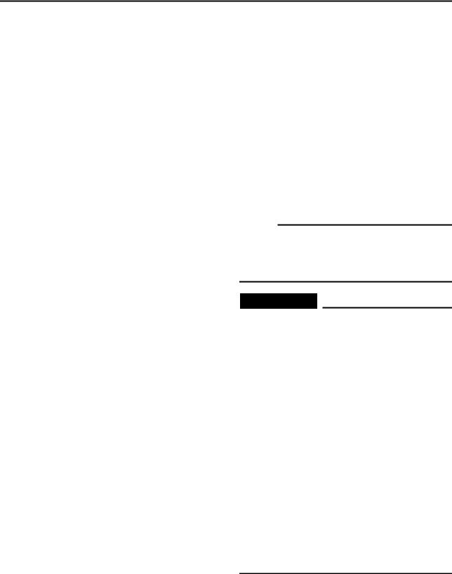
To help identify parts and clarify procedure steps, there are exploded diagrams at the start of each removal and disassembly section.
1.An easy-to-see exploded diagram 1 is provided for removal and disassembly jobs.
2.Numbers 2 are given in the order of the jobs in the exploded diagram. A number that is enclosed by a circle indicates a disassembly step.
3.An explanation of jobs and notes is presented in an easy-to-read way by the use of symbol marks 3. The meanings of the symbol marks are given on the next page.
4.A job instruction chart 4 accompanies the exploded diagram, providing the order of jobs, names of parts, notes in jobs, etc.
5.Extent of removal 5 is provided in the job instruction chart to save the trouble of an unnecessary removal job.
6.For jobs requiring more information, the step-by-step format supplements 6 are given in addition to the exploded diagram and job instruction chart.

FORMAT DU MANUEL
Dans ce manuel, toutes les procédures sont décrites pas à pas. Les informations ont été condensées pour fournir à l’utilisateur un guide pratique et facile à lire, contenant des explications claires pour toutes les procédures de démontage, réparation, remontage et vérification.
Dans ce nouveau format, l’état d’un composant défectueux est suivi d’une flèche qui indique les mesures à prendre. Exemple:
•Roulements
Piqûres/endommagement → Remplacer.
COMMENT LIRE LES DESCRIPTIONS
Chaque section détaillant des étapes de démontage ou de remontage est précédée de vues en éclaté qui permettent de clarifier ces opérations.
1.Exemple de vue en éclaté 1 clarifiant les opérations de démontage et de remontage.
2.Sur les vues en éclaté, les pièces sont numérotées 2 dans l’ordre des opérations à effectuer. Un chiffre entouré d’un cercle correspond à une étape de démontage.
3.Les vues en éclaté portent également des symboles 3 qui rappellent des point importants à ne pas oublier. La signification de ces symboles est expliquée à la page suivante.
4.Les vues en éclaté sont suivies d’un tableau 4 fournissant l’ordre des opérations, le nom des pièces, des remarques, etc.
5.Pour éviter la dépose superflue de pièces, l’organisation de la dépose 5 est indiquée dans le tableau de description du travail.
6.Pour les travaux qui demandent des explications supplémentaires, la vue en éclaté et le tableau sont suivis d’une description détaillée 6 des opérations.
AUFBAU DER ANLEITUNG
Sämtliche Arbeitsvorgänge in dieser Anleitung sind in der entsprechenden Reihenfolge dargestellt. Diese Anleitung wurde zusammengestellt, um dem Benutzer ein leicht verständliches Nachschlagewerk in die Hand zu geben, in dem Einund Ausbau, Zerlegung und Zusammenbau, Prüfung und Reparatur detailliert beschrieben sind.
Je nach Zustand eines fehlerhaften Bauteils weist ein Pfeilsymbol auf die erforderliche Maßnahme hin. Beispiel:
•Lager
Angefressen/beschädigt → Erneuern.
BESCHREIBUNGEN
In jedem Kapitel befinden sich Explosionszeichnungen, die die richtige Reihenfolge beim Zerlegen oder Zusammenbau einzelner Teile oder Baugruppen veranschaulichen.
1.Eine übersichtliche Explosionszeichnung 1 verdeutlicht die Ausbauund Zerlegungsarbeiten.
2.Die in den Explosionszeichnungen dargestellten Teile sind in der Arbeitsreihenfolge nummeriert.2. Die eingekreisten Nummern verweisen auf Zerlegungsschritte.
3.Leicht verständliche Symbole 3 geben zusätzliche Informationen. Die Bedeutungen der Symbole sind auf der folgenden Seite aufgeführt.
4.Eine Tätigkeitsübersicht 4 begleitet die Explosionszeichnungen und führt Arbeitsreihenfolge, Bauteilbezeichnung, Stückzahl und besondere Bemerkungen auf.
5.Der Umfang des Ausbaus 5 ist in der Tätigkeitsübersicht aufgeführt, um unnötige Ausbauarbeiten zu vermeiden.
6.Für Arbeiten, die weitergehende Informationen benötigen, werden zusätzlich zur Explosionszeichnung und Tätigkeitsübersicht ergänzende Schrittfolgen 6 aufgeführt.
1 |
2 |
|
GEN |
SPEC |
|
INFO |
|
|
|
|
|
3 |
4 |
|
INSP |
ENG |
|
ADJ |
|
|
|
|
|
5 |
6 |
|
CHAS |
ELEC – |
+ |
7 |
8 |
|
9 |
0 |
|
A |
B |
|
T |
|
|
. |
|
|
R |
|
|
. |
|
|
C |
D |
|
E |
F |
|
E |
M |
|
G |
H |
|
LS |
M |
|
I |
J |
|
LT |
New |
|
|
|
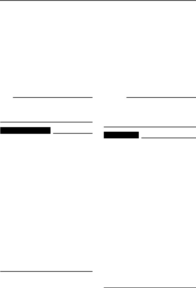
ILLUSTRATED SYMBOLS (Refer to the illustration)
Illustrated symbols 1 to 6 are designed as thumb tabs to indicate the chapter’s number and content.
1 General information
2Specifications
3Regular inspection and adjustments
4Engine
5Chassis
6Electrical
Illustrated symbols 7 to D are used to identify the specifications appearing in the text.
7 With engine mounted
8 Special tool
9 Filling fluid
0 Lubricant
ATightening
BSpecified value, Service limit
CEngine speed
DResistance (Ω), Voltage (V), Electric current (A)
Illustrated symbols E to H in the exploded diagram indicate grade of lubricant and location of lubrication point.
E Apply engine oil
F Apply molybdenum disulfide oil
GApply lightweight lithium-soap base grease
HApply molybdenum disulfide grease
Illustrated symbols I to J in the exploded diagrams indicate where to apply a locking agent and when to install new parts.
I Apply locking agent (LOCTITE®)
J Use new one

SYMBOLES GRAPHIQUES (Voir l’illustration)
Les symboles graphiques 1 à 6 servent a repérer les différents chapitres et à indiquer leur contenu.
1 Renseignements généraux
2Caractéristiques
3Contrôles et réglages périodiques
4Moteur
5Châssis
6Partie électrique
Les symboles graphiques 7 à D permettent d’identifier les caractéristiques apparaissant dans le texte.
7 Moteur monté
8 Outil spécial
9 Liquide de remplissage
0 Lubrifiant
ASerrage
BValeur spécifiée, limite de service
CRégime du moteur
DRésistance (Ω), tension (V), intensité (A)
Les symboles graphiques E à H utilisés dans les vues en éclaté indiquent les endroits à lubrifier et le type de lubrifiant à utiliser.
E Appliquer de l’huile moteur
F Appliquer de l’huile au bisulfure de molybdène
G Appliquer de la graisse fluide à base de savon au lithium
H Appliquer de la graisse au bisulfure de molybdène
SYMBOLE
(Siehe Abbildung.)
Die Symbole 1 bis 6 werden verwendet, um die Nummer und den Inhalt eines Kapitels anzuzeigen.
1Allgemeines
2Technische Daten
3Regelmäßige Wartungsund Einstellarbeiten
4Motor
5Fahrwerk
6Elektrische Anlage
Die Symbole 7 bis D weisen auf folgende wichtigen Angaben im Text hin.
7 Arbeit mit montiertem Motor
8Spezialwerkzeug
9Art und Menge einzufüllender Flüssigkeiten
0Schmiermittel A Anzugsmoment
B Sollund Grenzwerte
C Motordrehzahl
D Widerstand (Ω), Spannung (V), Stromstärke (A)
Die Symbole E bis H in den Explosionszeichnungen weisen auf die Schmiermittel und Schmierstellen hin.
E Motoröl auftragen
F Molybdändisulfidöl auftragen
G Leichtes Lithiumseifenfett auftragen H Molybdändisulfidfett auftragen
Les symboles graphiques I à J dans les vues en éclaté indiquent où appliquer un agent de blocage et les pièces à remplacer.
IAppliquer un agent de blocage (LOCTITE®)
JUtiliser une pièce neuve
Die Symbole I und J werden ebenfalls in den Explosionszeichnungen verwendet und weisen respketive auf Stellen hin, die mit Klebemittel oder neuen Bauteilen zu versehen sind.
IKlebemittel (LOCTITE®) auftragen
JErneuern
INDEX
GENERAL INFORMATION
SPECIFICATIONS
REGULAR INSPECTION AND ADJUSTMENTS
ENGINE
CHASSIS
ELECTRICAL
INDEX
RENSEIGNEMENTS GENERAUX
CARACTERISTIQUES
CONTROLES ET REGLAGES PERIODIQUES
MOTEUR
CHASSIS
PARTIE
ELECTRIQUE
INDEX
ALLGEMEINES |
GEN |
1 |
|
INFO |
|
TECHNISCHE |
|
2 |
DATEN |
SPEC |
|
|
REGELMÄSSIGE
WARTUNGSUND INSP 3 EINSTELLARBEITEN ADJ
MOTOR |
ENG |
4 |
|
||
FAHRWERK |
CHAS |
5 |
|
||
ELEKTRISCHE |
– |
+ |
|
6 |
|
ANLAGE |
ELEC |
|
|

CONTENTS
CHAPTER 1
GENERAL INFORMATION
DESCRIPTION ........................................... |
1-1 |
MACHINE IDENTIFICATION ..................... |
1-2 |
IMPORTANT INFORMATION .................... |
1-3 |
CHECKING OF CONNECTION ................. |
1-5 |
SPECIAL TOOLS ...................................... |
1-6 |
CONTROL FUNCTIONS ............................ |
1-9 |
FUEL ........................................................ |
1-12 |
STARTING AND OPERATION ................ |
1-13 |
CLEANING AND STORAGE ................... |
1-14 |
CHAPTER 2
SPECIFICATIONS
GENERAL SPECIFICATIONS ................... |
2-1 |
MAINTENANCE SPECIFICATIONS .......... |
2-4 |
GENERAL TORQUE |
|
SPECIFICATIONS ................................... |
2-17 |
DEFINITION OF UNITS ........................... |
2-17 |
CABLE ROUTING DIAGRAM ................. |
2-18 |
CHAPTER 3
REGULAR INSPECTION AND
ADJUSTMENTS
MAINTENANCE INTERVALS ................... |
3-1 |
PRE-OPERATION INSPECTION AND |
|
MAINTENANCE ......................................... |
3-3 |
ENGINE ...................................................... |
3-4 |
CHASSIS ................................................. |
3-12 |
ELECTRICAL ........................................... |
3-23 |

TABLES DES MATIERES
CHAPITRE 1
RENSEIGNEMENTS
GENERAUX
DESCRIPTION ............................................... |
1-1 |
IDENTIFICATION DE LA MOTO .............. |
1-2 |
INFORMATIONS IMPORTANTES ............ |
1-3 |
VERIFICATION DES CONNEXIONS ........ |
1-5 |
OUTILS SPECIAUX ...................................... |
1-6 |
FONCTIONS DES COMMANDES .............. |
1-9 |
CARBURANT ............................................... |
1-12 |
DEMARRAGE ET |
|
FONCTIONNEMENT .................................. |
1-13 |
NETTOYAGE ET REMISAGE .................. |
1-14 |
CHAPITRE 2
CARACTERISTIQUES
CARACTERISTIQUES GENERALES ........ |
2-1 |
CARACTERISTIQUES D’ENTRETIEN ..... |
2-4 |
CARACTERISTIQUES GENERALES DE |
|
COUPLE ........................................................ |
2-17 |
DEFINITION DES UNITES ........................ |
2-17 |
CHEMINEMENT DES CABLES ................ |
2-18 |
CHAPITRE 3
CONTROLES ET REGLAGES
PERIODIQUES
PROGRAMME D’ENTRETIEN ................... |
3-1 |
CONTROLES ET ENTRETIENS |
|
AVANT UTILISATION ................................. |
3-3 |
MOTEUR ......................................................... |
3-4 |
CHASSIS ........................................................ |
3-12 |
PARTIE ELECTRIQUE .............................. |
3-23 |
INHALT
KAPITEL 1
ALLGEMEINES
FAHRZEUGBESCHREIBUNG .................. |
1-1 |
FAHRZEUG-IDENTIFIZIERUNG ............... |
1-2 |
WICHTIGE INFORMATIONEN .................. |
1-3 |
KABELANSCHLÜSSE |
|
KONTROLLIEREN .................................... |
1-5 |
SPEZIALWERKZEUGE ............................. |
1-6 |
BEDIENUNGSELEMENTE UND |
|
DEREN FUNKTION ................................... |
1-9 |
KRAFTSTOFF ......................................... |
1-12 |
ANLASSEN UND INBETRIEBNAHME ...1-13 |
|
REINIGUNG UND STILLLEGUNG .......... |
1-14 |
KAPITEL 2
TECHNISCHE DATEN
ALLGEMEINE TECHNISCHE DATEN |
......2-1 |
WARTUNGSDATEN .................................. |
2-4 |
ALLGEMEINE ANZUGSMOMENTE ....... |
2-17 |
MASSEINHEITEN .................................... |
2-17 |
KABELFÜHRUNGSDIAGRAMME .......... |
2-18 |
KAPITEL 3
REGELMÄSSIGE
WARTUNGSUND
EINSTELLARBEITEN
WARTUNGSINTERVALLE ........................ |
3-1 |
ROUTINEKONTROLLE VOR |
|
FAHRTBEGINN ......................................... |
3-3 |
MOTOR ...................................................... |
3-4 |
FAHRWERK ............................................ |
3-12 |
ELEKTRISCHE ANLAGE ........................ |
3-23 |

CHAPTER 4
ENGINE
CARBURETOR .......................................... |
4-1 |
CYLINDER HEAD ...................................... |
4-8 |
CAMSHAFT AND ROCKER ARMS ........ |
4-13 |
VALVES AND VALVE SPRINGS ............ |
4-16 |
CYLINDER AND PISTON ........................ |
4-21 |
CLUTCH ................................................... |
4-27 |
KICK AXLE .............................................. |
4-33 |
SHIFT SHAFT .......................................... |
4-34 |
OIL PUMP ................................................ |
4-36 |
CDI MAGNETO (TT-R90) ........................ |
4-39 |
CDI MAGNETO AND |
|
STARTER CLUTCH (TT-R90E) ............... |
4-41 |
CRANKCASE AND CRANKSHAFT ........ |
4-45 |
SHIFT FORK, SHIFT CAM AND |
|
TRANSMISSION ...................................... |
4-48 |
CHAPTER 5
CHASSIS
FRONT WHEEL AND REAR WHEEL |
.......5-1 |
FRONT FORK .......................................... |
5-10 |
HANDLEBAR ........................................... |
5-13 |
STEERING ............................................... |
5-18 |
SWINGARM ............................................. |
5-20 |
CHAPTER 6
ELECTRICAL
ELECTRICAL COMPONENTS AND |
|
WIRING DIAGRAM .................................... |
6-1 |
IGNITION SYSTEM .................................... |
6-3 |
ELECTRIC STARTING SYSTEM |
|
(TT-R90E) .................................................. |
6-7 |
CHARGING SYSTEM (TT-R90E) ............ |
6-15 |
CARBURETOR HEATING SYSTEM ....... |
6-17 |
MAINTENANCE RECORD ...................... |
6-21 |

CHAPITRE 4
MOTEUR
CARBURATEUR ............................................ |
4-1 |
CULASSE ........................................................ |
4-8 |
ARBRE A CAMES ET CULBUTEURS ..... |
4-13 |
SOUPAPES ET RESSORTS DE |
|
SOUPAPE ...................................................... |
4-16 |
CYLINDRE ET PISTON ............................. |
4-21 |
EMBRAYAGE .............................................. |
4-27 |
ARBRE DE KICK ......................................... |
4-33 |
AXE DE SELECTEUR ................................. |
4-34 |
POMPE A HUILE ......................................... |
4-36 |
VOLANT MAGNETIQUE CDI (TT-R90) ... |
4-39 |
VOLANT MAGNETIQUE CDI ET |
|
EMBRAYAGE |
|
DU DEMARREUR (TT-R90E) .................... |
4-41 |
CARTER MOTEUR ET |
|
VILEBREQUIN ............................................ |
4-45 |
FOURCHETTE DE SELECTION, |
|
TAMBOUR ET BOITE DE VITESSES ..... |
4-48 |
CHAPITRE 5
CHASSIS
ROUE AVANT ET ROUE ARRIERE |
.......... 5-1 |
FOURCHE ..................................................... |
5-10 |
GUIDON ........................................................ |
5-13 |
DIRECTION .................................................. |
5-18 |
BRAS OSCILLANT ...................................... |
5-20 |
CHAPITRE 6
PARTIE ELECTRIQUE
COMPOSANTS ELECTRIQUES ET |
|
SCHEMA DE CABLAGE .............................. |
6-1 |
SYSTEME D’ALLUMAGE ........................... |
6-3 |
SYSTEME DE DEMARRAGE |
|
ELECTRIQUE (TT-R90E) ............................ |
6-7 |
SYSTEME DE CHARGE (TT-R90E) ......... |
6-15 |
SYSTEME DE RECHAUFFAGE DU |
|
CARBURATEUR .......................................... |
6-17 |
FICHE D’ENTRETIEN ............................... |
6-21 |
KAPITEL 4
MOTOR
VERGASER ............................................... |
4-1 |
ZYLINDERKOPF ....................................... |
4-8 |
NOCKENWELLE UND KIPPHEBEL ....... |
4-13 |
VENTILE UND VENTILFEDERN ............. |
4-16 |
ZYLINDER UND KOLBEN ...................... |
4-21 |
KUPPLUNG ............................................. |
4-27 |
KICKHEBELWELLE ................................ |
4-33 |
SCHALTWELLE ...................................... |
4-34 |
ÖLPUMPE ................................................ |
4-36 |
LICHTMASCHINE (TT-R90) .................... |
4-39 |
LICHTMASCHINE UND |
|
STARTERKUPPLUNG (TT-R90E) .......... |
4-41 |
KURBELGEHÄUSE UND |
|
KURBELWELLE ...................................... |
4-45 |
SCHALTGABELN, SCHALTWALZE UND |
|
GETRIEBE ............................................... |
4-48 |
KAPITEL 5
FAHRWERK
VORDERUND HINTERRAD |
....................5-1 |
TELESKOPGABEL ................................. |
5-10 |
LENKER ................................................... |
5-13 |
LENKUNG ................................................ |
5-18 |
SCHWINGE .............................................. |
5-20 |
KAPITEL 6
ELEKTRISCHE ANLAGE
ELEKTRISCHE BAUTEILE UND |
|
SCHALTPLAN ........................................... |
6-1 |
ZÜNDSYSTEM ........................................... |
6-3 |
STARTSYSTEM (TT-R90E) ....................... |
6-7 |
LADESYSTEM (TT-R90E) ....................... |
6-15 |
VERGASERHEIZUNG ............................. |
6-17 |
VERZEICHNIS DER |
|
WARTUNGSARBEITEN .......................... |
6-21 |
GEN
DESCRIPTION INFO
1 |
|
4 |
2 |
3 |
5 |
|
||
|
6 |
|
EC100000
GENERAL INFORMATION
EC110000
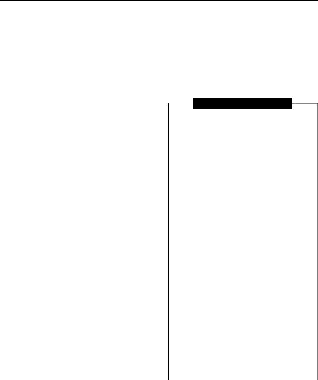
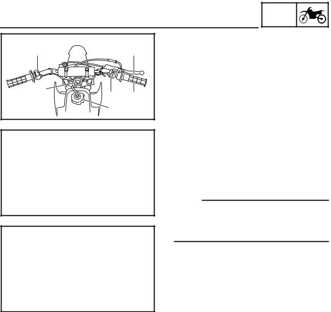
DESCRIPTION
1 “ENGINE STOP” switch
2Main switch (TT-R90E)
3Start switch (TT-R90E)
4Front brake lever
5Throttle grip
6Fuel tank cap
7Kick starter
8Fuel tank
9Air cleaner
0 Rear brake pedal A Fuel cock
B Starter lever (choke) C Drive chain
D Shift pedal E Front fork
NOTE:
•The machine you have purchased may differ slightly from those shown in the following.
•Designs and specifications are subject to change without notice.
The illustration shows the TT-R90E.
1 - 1
|
|
|
|
|
|
|
|
|
|
|
|
|
|
|
DESCRIPTION |
|
GEN |
|
|
|
|||||
|
FAHRZEUGBESCHREIBUNG |
|
INFO |
|
|
|
||||||
|
|
|
|
|
|
|
|
|
|
|
|
|
RENSEIGNEMENTS |
ALLGEMEINES |
|
|
|
|
|
||||||
GENERAUX |
FAHRZEUGBESCHREIBUNG |
|||||||||||
DESCRIPTION |
1 Motorstoppschalter “ENGINE STOP” |
|||||||||||
1 Coupe-circuit du moteur |
2 Zündschloss (TT-R90E) |
|
|
|
|
|
||||||
3 Starterschalter (TT-R90E) |
|
|
|
|
|
|||||||
2 Contacteur à clé (TT-R90E) |
|
|
|
|
|
|||||||
4 Handbremshebel |
|
|
|
|
|
|
|
|
||||
3 Contacteur du démarreur (TT-R90E) |
|
|
|
|
|
|
|
|
||||
5 Gasdrehgriff |
|
|
|
|
|
|
|
|
||||
4 Levier de frein avant |
|
|
|
|
|
|
|
|
||||
6 Tankverschluss |
|
|
|
|
|
|
|
|
||||
5 Poignée d’accélérateur |
|
|
|
|
|
|
|
|
||||
7 Kickstarterhebel |
|
|
|
|
|
|
|
|
||||
6 Bouchon du réservoir de carburant |
|
|
|
|
|
|
|
|
||||
8 Kraftstofftank |
|
|
|
|
|
|
|
|
||||
7 Kick |
|
|
|
|
|
|
|
|
||||
9 Luftfilter |
|
|
|
|
|
|
|
|
||||
8 Réservoir de carburant |
|
|
|
|
|
|
|
|
||||
0 Fußbremshebel |
|
|
|
|
|
|
|
|
||||
9 Filtre à air |
|
|
|
|
|
|
|
|
||||
A Kraftstoffhahn |
|
|
|
|
|
|
|
|
||||
0 Pédale de frein arrière |
|
|
|
|
|
|
|
|
||||
B Chokehebel |
|
|
|
|
|
|
|
|
||||
A Robinet de carburant |
|
|
|
|
|
|
|
|
||||
C Antriebskette |
|
|
|
|
|
|
|
|
||||
B Levier de starter |
|
|
|
|
|
|
|
|
||||
D Fußschalthebel |
|
|
|
|
|
|
|
|
||||
C Chaîne de transmission |
|
|
|
|
|
|
|
|
||||
E Gabelholm |
|
|
|
|
|
|
|
|
||||
D Sélecteur |
|
|
|
|
|
|
|
|
||||
HINWEIS: |
|
|
|
|
|
|
|
|
|
|||
E Fourche |
|
|
|
|
|
|
|
|
|
|||
|
|
|
|
|
|
|
|
|
||||
N.B.: |
|
• Die Abbildungen in |
vorliegender Anleitung |
|||||||||
|
können leicht |
vom |
eigentlichen Modell |
|||||||||
• Votre moto diffère peut-être partiellement de |
||||||||||||
abweichen und |
dienen |
daher |
lediglich zur |
|||||||||
celle montrée sur ces photos. |
||||||||||||
Bezugnahme. |
|
|
|
|
|
|
|
|
||||
• La conception et les caractéristiques peuvent être |
|
|
|
|
|
|
|
|
||||
• Änderungen an |
Design und |
technischen |
||||||||||
|
|
|||||||||||
modifiées sans préavis.
Daten jederzeit vorbehalten.
L’illustration représente la TT-R90E.
Das abgebildete Modell ist TT-R90E.
1 |
1 - 1
 (EV) 2006 Owner's manual")
MACHINE IDENTIFICATION
EC120001
GEN  INFO
INFO 

1
1
MACHINE IDENTIFICATION
There are two significant reasons for knowing the serial number of your machine:
1.When ordering parts, you can give the number to your Yamaha dealer for positive identification of the model you own.
2.If your machine is stolen, the authorities will need the number to search for and identify your machine.
KEY IDENTIFICATION NUMBER (TT-R90E)
The key identification number 1 is stamped on the key as shown in the following illustration. This number can be used for ordering a new key.
EC121001
VEHICLE IDENTIFICATION NUMBER
The vehicle identification number 1 is stamped on the right of the steering head pipe.
ENGINE SERIAL NUMBER
The engine serial number 1 is stamped into the elevated part of the left-side of the engine.
EC124000
MODEL LABEL
The model label 1 is affixed to the frame under the rider’s seat. This information will be needed to order spare parts.
1 - 2

IDENTIFICATION DE LA MOTO
FAHRZEUG-IDENTIFIZIERUNG
GEN  INFO
INFO 

IDENTIFICATION DE LA MOTO
Il y a deux bonnes raisons de connaître le numéro de série de sa moto:
1.A la commande de pièces de rechange, ces numéros permettent au concessionnaire Yamaha d’identifier clairement la moto.
2.En cas de vol de la moto, la police réclamera ce numéro afin de faciliter son identification.
NUMERO D’IDENTIFICATION DE LA CLE (TT-R90E)
Le numéro d’identification de la clé 1 est estampé sur la clé comme indiqué sur l’illustration suivante. Ce numéro peut être utilisé pour la commande d’une nouvelle clé.
FAHRZEUG-IDENTIFIZIERUNG
Die Fahrzeug-Identifizierungsnummer ist in folgenden Fällen erforderlich:
1.Bei der Bestellung von Ersatzteilen benötigt der Yamaha-Händler diese Nummer zur exakten Identifizierung des Modells.
2.Bei Diebstahl benötigt die Polizei diese Nummer zur exakten Identifizierung des Modells.
SCHLÜSSEL-IDENTIFIZIERUNGSNUMMER (TT-R90E)
Die Schlüssel-Identifizierungsnummer 1 ist wie in der Abbildung gezeigt auf dem Schlüssel eingestanzt. Diese Nummer dient zur Nachbestellung eines Schlüssels.
NUMERO D’IDENTIFICATION DE LA MOTO
Le numéro d’identification de la moto 1 est estampé sur le côté droit du tube de direction.
NUMERO DE SERIE DU MOTEUR
Le numéro de série du moteur 1 est estampé sur la partie surélevée du côté gauche du moteur.
ETIQUETTE DE MODELE
L’étiquette de modèle 1 est apposée sur le cadre, sous la selle du pilote. Les informations reprises sur cette étiquette sont requises lors de la commande de pièces de rechange.
FAHRZEUG-IDENTIFIZIERUNGSNUMMER
Die Fahrzeug-Identifizierungsnummer 1 ist auf der rechten Seite des Lenkkopfrohres eingeschlagen.
MOTOR-IDENTIFIZIERUNGSNUMMER
Die Motor-Identifizierungsnummer 1 ist an der gezeigten Stelle rechts im Kurbelgehäuse eingeschlagen.
MODELLCODE-KLEBESCHILD
Das Modellcode-Klebeschild 1 ist auf dem Rahmen unter dem Fahrersitz angebracht. Die Codenummer und das Info-Kürzel werden zur Ersatzteilbestellung benötigt.
1 - 2
GEN
IMPORTANT INFORMATION INFO
EC130000
IMPORTANT INFORMATION
EC131002
PREPARATION FOR REMOVAL AND
DISASSEMBLY
1.Remove all dirt, mud, dust, and foreign material before removal and disassembly. When washing the machine with high pressured water, cover the parts as follows.
• Silencer exhaust port
2.Use proper tools and cleaning equipment. Refer to “SPECIAL TOOLS” section.
3.When disassembling the machine, keep mated parts together. They include gears, cylinders, pistons, and other mated parts that have been “mated” through normal wear. Mated parts must be reused as an assembly or replaced.
4.During the machine disassembly, clean all parts and place them in trays in the order of disassembly. This will speed up assembly time and help assure that all parts are correctly reinstalled.
5.Keep away from fire.
1 - 3
Loading...