


G B
TSX-10 TSX-15
TSX-20
TABLETOP STEREO SYSTEM SYSTEM HIFI TABLETOP
OWNER’S MANUAL
MODE D’EMPLOI BEDIENUNGSANLEITUNG BRUKSANVISNING
MANUALE DI ISTRUZIONI
MANUAL DE INSTRUCCIONES GEBRUIKSAANWIJZING
CAUTION
Use of controls or adjustments or performance of procedures other than those specified herein may result in hazardous radiation exposure.
ATTENTION
L’emploi de commandes, de réglages ou un choix de procédures différents des spécifications de cette brochure peut entraîner une exposition à d’éventuelles radiations pouvant être dangereses.
ACHTUNG
Die Verwendung von Bedienungselementen oder Einstellungen oder die Durchführung von Bedienungsvorgängen, die nicht in dieser Anleitung aufgeführt sind, kann zu einem Kontakt mit gefährlichen Laserstrahlen führen.
OBSERVERA
Användning av kontroller och justeringar eller genomförande av andra procedurer än de som specificeras i denna bok kan resultera i att du utsätter dig för farlig strålning.
ATTENZIONE
Uso di controlli o regolazioni o procedure non specificamente descritte può causare l’esposizione a radiazioni di livello pericoloso.
PRECAUCIÓN
El uso de los controles o los procedimientos de ajuste o utilización diferentes de los especificados en este manual pueden causar una exposición peligrosa a la radiación.
VOORZICHTIG
Gebruik van bedieningsorganen of instellingen, of uitvoeren van handelingen anders dan staan beschreven in deze handleiding kunnen leiden tot blootstelling aan gevaarlijke stralen.
VARO!
AVATTAESSA JA SUOJALUKITUS
OHITETTAESSA OLET ALTTIINA NÄKYMÄTTÖMÄLLE LASERSÄTEILYLLE. ÄLÄ KATSO SÄTEESEEN.
VARNING!
OSYNLIG LASERSTRÅLNING NÄR DENNA DEL ÄR ÖPPNAD OCH SPÄRREN ÄR URKOPPLAD. BETRAKTA EJ STRÅLEN.
|
CLASS 1 LASER PRODUCT |
|
LASER KLASSE 1 PRODUKT |
|
LUOKAN 1 LASERLAITE |
|
KLASS 1 LASER APPARAT |
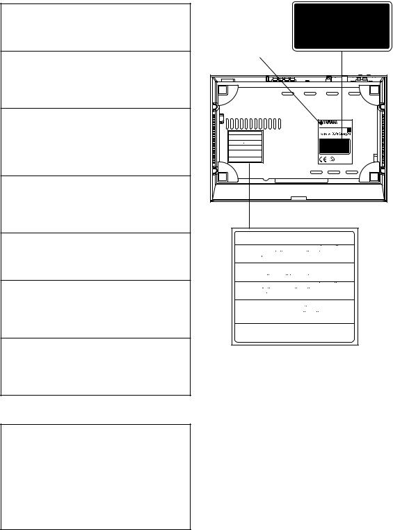
* |
|
|
MODEL NO. CRX-TS10 |
|
230 VOLTS 35 WATTS |
CAUTION - VISIBLE AND/OR INVISIBLE LASER RADIATION WHEN OPEN |
50 Hz ~ |
AND INTERLOCKS DEFEATED.AVOID EXPOSURE TO BEAM. |
|
VARNING - SYNLIG OCH/ELLER OSYNLIG LASERSTRALNING NAR |
MADE IN MALAYSIA |
DENNA DEL AR OPPNAD OCH SPARRAR AR URKOPPLADE. |
|
STRALEN AR FARLIG. |
|
VARO ! AVATTAESSA JA SUOJALUKITUS OHITETTAESSA OLET |
|
ALTTINA NAKYVALLE JA/TAI NAKYMATOMALLE |
CLASS 1 LASER PRODUCT |
LASERSATEILYLLE. ALA KATSO SATEESEEN. |
|
VARNING - SYNLIG OCH/ELLER OSYNLIG LASERSTRALNING NAR DENNA |
LASER KLASSE 1 PRODUKT |
DEL AR OPPNAD OCH SPARREN AR URKOPPLAD. BETRAKTA |
LUOKAN 1 LASERLAITE |
EJ STRALEN. |
KLASS 1 LASER APPARAT |
VORSICHT ! SICHTBARE UND/ODER UNSICHTBARE LASERSTRAHLUNG |
|
TRITT AUS,WENN DECKEL GEOFFNET UND WENN |
|
SICHERHEITSVERRIEGELUNG UBERBRUCKT IST. |
|
NICHT DEM STRAHL AUSSETZEN. |
|
ATTENTION - RADIATION LASER VISIBLE ET/OU INVISIBLE LORSQUE
L´APPAREIL EST OUVERT ET QUE LE VERROUILLAGE EST
DESACTIVE. EVITEZ TOUTE EXPOSITION AU FAISCEAU.
CAUTION - VISIBLE AND/OR INVISIBLE LASER RADIATION WHEN OPEN
AND INTERLOCKS DEFEATED. AVOID EXPOSURE TO BEAM.
VARNING - SYNLIG OCH/ELLER OSYNLIG LASERSTRALNING NAR
DENNA DEL AR OPPNAD OCH SPARRAR AR URKOPPLADE.
STRALEN AR FARLIG.
VARO ! AVATTAESSA JA SUOJALUKITUS OHITETTAESSA OLET
ALTTINA NAKYVALLE JA/TAI NAKYMATOMALLE
LASERSATEILYLLE. ALA KATSO SATEESEEN.
VARNING - SYNLIG OCH/ELLER OSYNLIG LASERSTRALNING NAR DENNA
DEL AR OPPNAD OCH SPARREN AR URKOPPLAD. BETRAKTA
EJ STRALEN.
VORSICHT ! SICHTBARE UND/ODER UNSICHTBARE LASERSTRAHLUNG
TRITT AUS,WENN DECKEL GEOFFNET UND WENN
SICHERHEITSVERRIEGELUNG UBERBRUCKT IST.
NICHT DEM STRAHL AUSSETZEN.
ATTENTION - RADIATION LASER VISIBLE ET/OU INVISIBLE LORSQUE
L´APPAREIL EST OUVERT ET QUE LE VERROUILLAGE EST
DESACTIVE. EVITEZ TOUTE EXPOSITION AU FAISCEAU.
*: This label also shows the model number, required voltage and power consumption of this unit, and other cautions, etc.
ENGLISH
INTRODUCTION
Thank you for purchasing this YAMAHA product. We hope it will give you many years of trouble-free enjoyment. For the best performance, read this manual carefully. It will guide you in operating your YAMAHA product.
This owner’s manual covers three packages TSX-10, TSX-15 and TSX-20.
Please check the package number of your product and its components by refering to the following table.
Package number |
Components |
|
|
|
|
|
CD receiver |
Speaker system |
|
|
|
TSX-10 |
CRX-TS10 |
NX-TS10 |
|
|
|
TSX-15 |
CRX-TS20 |
NX-TS10 |
|
|
|
TSX-20 |
CRX-TS20 |
NX-TS20 |
|
|
|
FEATURES
• Output Power per Channel |
CD Player |
18 W + 18 W (4Ω, 1 kHz, 10% THD) |
• S-bit DAC and 8fs Digital Filter |
• Installation-free design |
• Optical Digital Output |
• Full Operation Remote Control |
• Random and Repeat Play |
• Multi-Function Timer/Sleep Timer |
Speakers |
• SUBWOOFER Output Terminal |
|
Tuner |
• 2-Way Bass-Reflex Speaker System |
Magnetic Shielding Type |
|
• 40-Station FM/AM Preset Tuning |
|
• Multi-Function RDS Reception |
|
|
|
SUPPLIED ACCESSORIES |
|
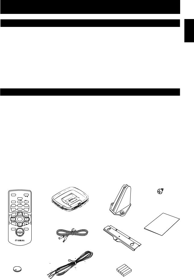
After unpacking, check that the following parts are included.
• Remote control |
• AM loop antenna |
• Stand x 3 |
• Screw x 9 |
||
SLEEP |
|
STANDBY/ON |
|
|
|
|
B. BOOST |
|
|
|
|
BASS/TREBLE |
LEVEL |
|
|
• Paper pattern |
|
FREQ/RDS |
RTY SEEK |
|
|
||
|
MODE |
START |
|
|
|
|
TUNER |
|
|
|
|
PRESET |
ABCDE |
PRESET |
|
|
|
REP |
|
RANDOM |
• Indoor FM antenna |
• Mounting bracket |
|
|
INPUT |
|
|
||
TIME |
|
|
|
|
|
MUTE |
VOL |
DISPLAY |
|
|
|
|
|
|
|
|
|
• Speaker cable x 2
• Battery (CR2025) |
• Non-slip pad x 4 |
English
1

CONTENTS |
|
INTRODUCTION ..................................... |
1 |
FEATURES .............................................. |
1 |
SUPPLIED ACCESSORIES ....................... |
1 |
SETTING UP THIS SYSTEM .................... |
2 |
PRECAUTIONS ....................................... |
3 |
NAMES OF BUTTONS AND CONTROLS |
|
Front panel ........................................................... |
4 |
Display................................................................. |
4 |
Remote control .................................................... |
5 |
GETTING STARTED |
|
Connections ......................................................... |
6 |
Installation ........................................................... |
8 |
CD preventive care ............................................ |
10 |
Remote control .................................................. |
11 |
Setting the clock ................................................ |
12 |
Adjusting the brightness of the display ............. |
12 |
LISTENING TO A SOURCE .................... |
13 |
COMPACT DISC PLAYER OPERATIONS
CD play.............................................................. |
14 |
Selecting the time display.................................. |
15 |
Random-sequence play...................................... |
15 |
Repeat play ........................................................ |
16 |
TUNER OPERATIONS |
|
Listening to the radio ......................................... |
17 |
Presetting stations .............................................. |
18 |
RECEIVING RDS STATIONS |
|
Receiving RDS data .......................................... |
19 |
PTY SEEK mode............................................... |
20 |
Optional settings for RDS functions ................. |
21 |
USING THE BUILT-IN TIMER |
|
Timer play ......................................................... |
22 |
Sleep timer ......................................................... |
23 |
ADDITIONAL INFORMATION |
|
Troubleshooting ................................................. |
24 |
Specifications .................................................... |
26 |
SETTING UP THIS SYSTEM
When not using the stands
400mm
100mm
10mm
100mm |
When using the stands
50mm
400mm
100mm
10mm
Set up this system by allowing spaces specified in the figure or more around and behind the main unit to assure good ventilation. To prevent the ventilation holes from being obstructed, be sure not to place another unit or any object on top of the main unit. Otherwise, it may cause fire or damage to the main unit.
Cautions
•If the main unit is put inside a rack, the front of it must be fully open.
•When mounting this system on the wall, allow spaces specified in the figure around the system as well, however, the space between the system and the wall is determined by the mounting bracket and screws used.
•When mounting this system on the wall, make sure that there is no metalic projection on the wall. If a metallic projection get into an opening of the main unit, it may cause fire or an electric shock to the user.
2
PRECAUTIONS: READ THIS BEFORE OPERATING THIS SYSTEM
1To assure the best performance, please read this manual carefully. Keep it in a safe place for future reference.
2To avoid humming sounds, position this system away from other electrical appliances, motors and transformers. To prevent fire or electrical shock, do not place this system where it may get exposed to rain or any kind of liquid.
3Avoid extreme temperature fluctuations or excessive use of a humidifier in the room where this system is installed to prevent condensation inside this system, which may cause an electrical shock, fire damage to this unit, and/or personal injury.
4In order not to obstruct heat radiation, do not cover the main unit with a newspaper, a tablecloth, a curtain, etc. If the temperature inside the main unit rises, it may cause fire, damage to the main unit and/or personal injury.
5Avoid installing this system in a place where foreign objects and liquid might fall. It might cause a fire, damage to this system and/or personal injury. Do not place the following objects on this system:
•Other components, as they may cause damage and/or discolor the surface of this system.
•Burning objects (i.e., candles), as they may cause fire, damage to this system and/or personal injury.
•Containers with liquid in them, as they may cause an electrical shock to the user and/or damage to this system.
6Do not use force on switches, controls or connection cables. Never pull the cables when disconnecting them.
7Only the voltage specified on the main unit must be used. Using this system with a higher voltage than specified is dangerous and may result in fire or other accidents. YAMAHA will not be held responsible for any damage resulting from the use of this system with a voltage other than that specified.
8Placing the speakers on the same shelf or rack as the turntable can result in howling.
9Secure placement or installation is the owner’s responsibility.
YAMAHA shall not be liable for any accident caused by improper placement or installation of this system.
10Any time you note distortion, reduce the volume to a lower setting. Never allow the amplifier to be driven into “clipping”. Otherwise the speakers may be damaged.
11Do not attempt to clean this system with chemical solvents; this might damage the finish. Use a clean, dry cloth.
12Disconnect the power cord from the wall outlet when not planning to use this system for a long period of time, or during an electrical storm, as it could be damaged by lightning.
13Do not attempt to modify or fix this system yourself. Contact qualified YAMAHA service personnel when any service is needed. The cabinet should never be opened for any reason.
14Be sure to read the “Troubleshooting” section regarding common operating errors before concluding that this system is faulty.
The main unit is not disconnected from the AC power source as long as it is connected to the wall outlet, even if the unit itself is turned off. This state is called the standby mode. In this state, the unit is designed to consume a very small quantity of power.
CAUTION FOR CARRYING THE MAIN UNIT
Before carrying the main unit, first remove the disc from the unit, press STANDBY/ON to turn the unit off, then disconnect the AC power plug from the wall outlet.
SPECIAL INSTRUCTIONS FOR U.K. MODEL
IMPORTANT:
The wires in the mains lead are coloured in accordance with the following code:
Blue: NEUTRAL
Brown: LIVE
As the colours of the wires in the mains lead of this apparatus may not correspond with the coloured markings identifying the terminals in your plug, proceed as follows: The wire which is coloured BLUE must be connected to the terminal which is marked with the letter N or coloured BLACK. The wire which is coloured BROWN must be connected to the terminal which is marked with the letter L or coloured RED. Making sure that neither core is connected to the earth terminal of the three pin plug.
For U.K. customers
If the socket outlets in the home are not suitable for the plug supplied with this appliance, it should be cut off and an appropriate 3 pin plug fitted. For details, refer to the instructions described above.
Note: The plug severed from the mains lead must be destroyed, as a plug with bared flexible cord is hazardous if engaged in a live socket outlet.
CAUTION
Use of controls or adjustments or performance of procedures other than those specified herein may result in hazardous radiation exposure.
CLASS 1 LASER PRODUCT LASER KLASSE 1 PRODUKT LUOKAN 1 LASERLAITE KLASS 1 LASER APPARAT
This compact disc player is classified as a CLASS 1 LASER product.
The CLASS 1 LASER PRODUCT label is located on the rear panel.
The laser component in this product is capable of emitting radiation exceeding the limit for Class 1.
English
3
NAMES OF BUTTONS AND CONTROLS |
|
|
|
|
||||
|
|
|
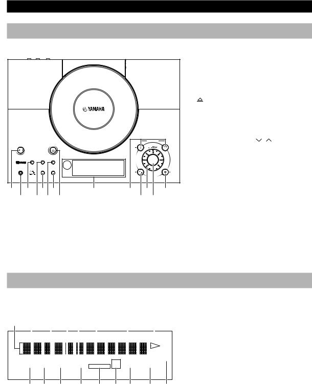
Front panel |
|
|
|
||
|
|
|
|
|
1 STANDBY/ON (P.13) |
|
|
|
|
|
|
|
|
2 PHONES (P.13) |
|
|
|
|
|
|
|
|
3 MEMORY/TIME ADJ (P.12, 18) |
|||
|
|
|
|
|
4 AUTO/MAN’L/TIMER (P.17, 22) |
|||
|
|
|
|
|
5 SLEEP (P.23) |
|
|
|
|
|
|
|
|
6 |
OPEN/CLOSE (P.14) |
|
|
|
|
|
|
|
7 DISPLAY (P.12, 22) |
|
|
|
|
|
|
|
|
8 PRESET/BAND (P.17) |
|
||
|
|
|
|
|
9 Display (P.4) |
|
|
|
|
|
|
PRESET/TUNING |
|
0 PRESET/TUNING |
/ |
(P.17) |
|
STANDBY/ON |
OPEN/CLOSE |
|
|
|
|
When TUNER is selected as an input |
||
|
|
|
HOUR |
|
HOUR |
|||
|
|
NATURAL SOUND CD RECEIVER |
|
|
|
source |
|
|
MEMORY AUTO/MAN´L PRESET/BAMD |
|
INPUT |
|
|
|
|
||
|
|
|
SNOOZE |
|
|
$/!/⁄/›(P.14) |
|
|
PHONES |
SLEEP DISPLAY |
PRESET STEREO AUTO RDS PSPTYRTCT REP TOTAL PROG TONE |
|
|
|
|
||
TIME ADJ |
TIMER |
|
|
|
|
|
|
|
|
|
TIMER SLEEP MEMORY TUNED PTY HOLD S F RANDOM B. BOOST |
MIN |
|
MIN |
|
|
|
|
|
|
|
When CD is selected as an input source |
||||
|
|
|
|
A/B/C/D/E |
|
|||
1 3 5 7 |
9 |
0 B |
D |
A ^(Play/Pause) (P.14) |
|
|
||
B VOLUME (P.13) |
|
|
||||||
2 4 8 6 |
|
A C |
|
|
|
|||
|
|
|
|
|
C INPUT/SNOOZE (P.8, 23) |
|||
|
|
|
|
|
D A/B/C/D/E (P.18) |
|
|
|
|
|
|
|
|
|
When TUNER is selected as an input |
||
|
|
|
|
|
|
source |
|
|
|
|
|
|
|
|
&(Stop) (P.14) |
|
|
|
|
|
|
|
|
When CD is selected as an input source |
||
Display
1 |
2 |
3 |
4 5 |
6 |
8 |
9 |
|
|
|
|
|
|
|
|
|
|
|
|
|
|
|
|
|
|
|
|
|
|
|
|
|
|
|
|
|
|
|
|
|
|
|
|
|
|
|
|
|
|
|
|
|
|
|
|
|
|
|
|
|
|
|
|
|
|
|
|
|
|
|
|
|
|
|
|
|
|
|
|
|
|
|
|
|
|
|
|
|
|
|
|
|
|
|
|
|
|
|
|
|
|
|
|
|
|
|
|
|
|
|
|
|
PRESET STEREO AUTO |
RDS |
PSPTYRTCT |
REP TOTAL |
TONE |
|
|||||||||
TIMER SLEEP MEMORY TUNED PTY HOLD S F RANDOM B. BOOST
0 A B C 7 D E F G
4
1 Multi information display
2 PRESET indicator (P.18)
3 STEREO indicator (P.17)
4 AUTO indicator (P.17)
5 RDS indicator (P.19)
6 RDS mode indicators (P.19)
7 PTY HOLD indicator (P.20)
8 TOTAL indicator (P.15)
9 B (Play) indicator (P.14)
0 TIMER indicator (P.22)
A SLEEP indicator (P.23)
B MEMORY indicator (P.18)
C TUNED indicator (P.17)
DREP S/F (repeat single/full) indicator (P.16)
E RANDOM indicator (P.15)
F B. BOOST (Bass boost) indicator (P.13)
G TONE indicator (P.13)

NAMES OF BUTTONS AND CONTROLS
Remote control
|
CRX-TS10/20 RDS V776930 |
|
||
2 |
SLEEP |
|
STANDBY/ON |
1 |
|
|
|
||
3 |
|
B. BOOST |
|
|
|
|
|
|
|
4 |
BASS/TREBLE |
LEVEL |
5 |
|
|
|
|
||
|
|
|
|
|
6 |
FREQ/RDS |
RTY SEEK |
7 |
|
|
MODE |
START |
||
8 |
|
TUNER |
|
|
PRESET |
ABCDE |
PRESET |
|
|
|
|
|||
9 |
|
|
|
|
0 |
|
|
RANDOM |
B |
AC |
REP |
|
||
|
|
|
||
|
|
INPUT |
|
|
D |
|
|
|
F |
E |
TIME |
|
|
|
H |
|
|
|
G |
MUTE |
VOL |
DISPLAY |
I |
J
1 STANDBY/ON (P.13)
2 SLEEP (P.23)
3 B. BOOST (Bass boost) (P.13)
4 BASS/TREBLE (P.13)
5 LEVEL +/– (P.13)
6 FREQ/RDS (P.19)
7 PTY SEEK MODE/START (P.20, 21)
8 A/B/C/D/E (P.18)
9 PRESET  /
/ (P.18)
0 ^(Play/Pause) (P.14)
A REP (Repeat) (P.16)
B RANDOM (Random) (P.15)
C INPUT (P.13)
D $!/⁄›(P.14)
E TIME (P.15)
F  (Open/Close) (P.14)
G &(Stop) (P.14)
H MUTE (P.13)
I DISPLAY (P.12, 22)
J VOL (Volume) +/– (P.13)
English
5
GETTING STARTED
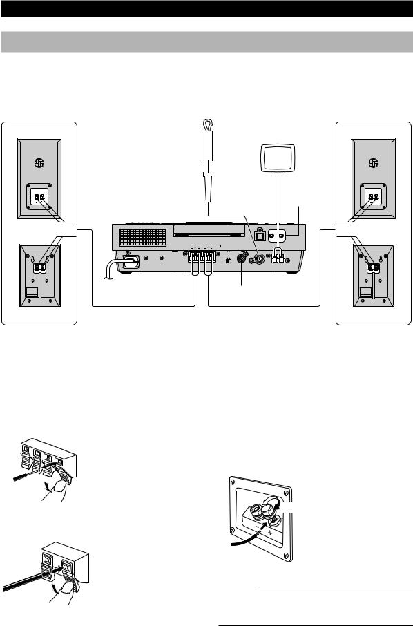
Connections
Never plug the AC power cord into the wall outlet until all connections are completed.
Follow the steps as shown below to connect the system using the supplied cables and accessories.
Right speaker |
Left speaker |
NX-TS20 |
NX-TS10 |
Indoor |
AM loop antenna |
FM antenna |
|
2 A
OUT IN
OPTICAL
|
|
|
|
CD DIGITAL OUT |
LINE |
|
4Ω MIN. /SPEAKER |
FOR USA : CLASS 2 WIRING |
|
|
|
|
|
SPEAKERS |
SETTING |
SUBWOOFER |
ANTENNA |
|
||
|
|
HRIZ |
OTHER |
OUT |
FM 75 Ω UNBAL. |
GND AM |
3 To wall outlet B
1
NX-TS20 |
NX-TS10 |
1 Connecting speakers
Connect the speakers to the SPEAKERS terminals of the main unit by using the speaker cables. Make sure that the polarity of the speaker cables is correct, i.e. the + and – markings are observed. If these cables are reversed, the sound will be unnatural and lack bass.
On the main unit
On the speakers
(NX-TS10)
Red: positive (+)
Black: negative (–)
1 Press the tab.
2Remove approx. 10 mm (3/8”) of insulation from each of the speaker cables and insert the bare
wire into the terminal.
3Release the tab and secure the cable.
On the speakers (NX-TS20)
Red: positive (+)
Black: negative (–)
Loosen
Tighten
1 Unscrew the knob.
2Remove approx. 10 mm (3/8”) of insulation from each of the speaker cables and insert the bare
wire into the terminal.
3Tighten the knob to secure the cable.
Caution
Do not let the bare speaker wires touch each other as this could damage the main unit and/or speakers.
6
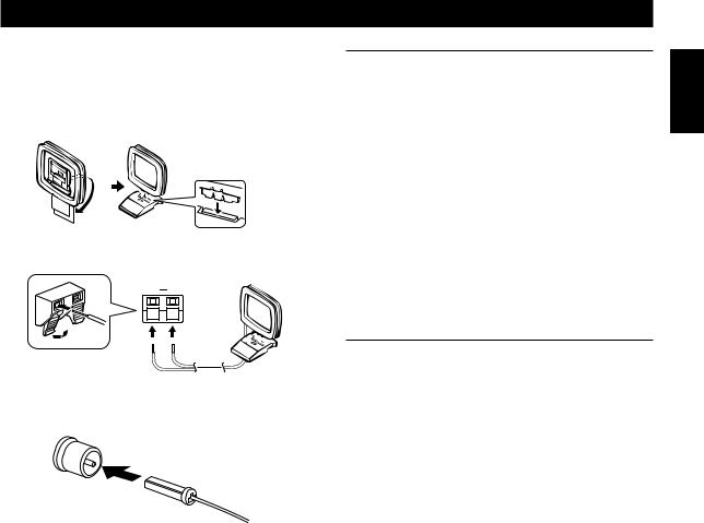
2 Connecting antennas
AM loop antenna
Set up the AM loop antenna, then connect it.
GND AM
GETTING STARTED
To enhance your system
A. To connect a Subwoofer (optional)
You can reinforce the bass frequencies by adding a subwoofer (optional).
Connect the SUBWOOFER OUT terminal of the main unit to the INPUT terminal of the subwoofer.
B. To connect an external component
•An external audio/video component can be connected to the LINE OUT (output) and/or IN (input) mini-jack terminals of the main unit.
•Digital-to-digital recording is possible from a CD played on this system to an MD (or tape) on an external MD (or DAT) recorder by connecting the CD DIGITAL OUT (OPTICAL) terminal on the rear of the main unit to the MD (or DAT) recorder.
English
3 Connecting to the wall outlet
Indoor FM antenna
Notes
•Use external FM/AM antennas if you need better reception. Consult your dealer.
•The AM loop antenna should be placed apart from the main unit. The antenna may be hung on a wall.
After all connections are finished, connect the AC power cord to a wall outlet.
7
 Loading...