


 E(Y) LW(Y) LWE(Y) 2009 Owner's manual")
 Read this manual carefully before operating this vehicle.
 Il convient de lire attentivement ce manuel avant la première utilisation du véhicule.
 Bitte lesen Sie diese Bedienungsanleitung sorgfalfig durch, bevor Sie das Fahrzeug in Betrieb nehmen.
OWNER´S MANUAL MANUEL DU PROPRIÉTAIRE BEDIENUNGSANLEITUNG
TT-R125(Y)
TT-R125E(Y)
TT-R125LW(Y)
TT-R125LWE(Y)
1B2-F8199-84

 Read this manual carefully before operating this vehicle.
OWNER´S MANUAL
TT-R125(Y)
TT-R125E(Y)
TT-R125LW(Y)
TT-R125LWE(Y)
1B2-F8199-84-E0
EAUW0770
 Read this manual carefully before operating this vehicle.This manual should stay with this vehicle if it is sold.

INTRODUCTION
EAU41662
Congratulations on your purchase of the YamahaTT-R125/ TT-R125E/ TT-R125LW/TT-R125LWE.This model is the result of Yamaha’s vast experience in the production of fine sporting, touring, and pacesetting racing machines. It represents the high degree of craftsmanship and reliability that have made Yamaha a leader in these fields.
This manual will give you an understanding of the operation, inspection, and basic maintenance of this motorcycle. If you have any questions concerning the operation or maintenance of your motorcycle, please consult a Yamaha dealer.
The design and manufacture of thisYamaha motorcycle fully comply with the emissions standards for clean air applicable at the date of manufacture.Yamaha has met these standards without reducing the performance or economy of operation of the motorcycle. To maintain these high standards, it is important that you and your Yamaha dealer pay close attention to the recommended maintenance schedules and operating instructions contained within this manual.
Yamaha continually seeks advancements in product design and quality. Therefore, while this manual contains the most current product information available at the time of printing, there may be minor discrepancies between your motorcycle and this manual. If there is any question concerning this manual, please consult a Yamaha dealer.
EWA10031
Please read this manual carefully and completely before operating this motorcycle.
EWA14351
This motorcycle is designed and manufactured for off-road use only. It is illegal to operate this motorcycle on any public street, road or highway. Such use is prohibited by law. This motorcycle complies with almost all state offhighway noise level and spark arrester laws and regulations. Please check your local riding laws and regulations before operating this motorcycle.

INTRODUCTION
AN IMPORTANT SAFETY MESSAGE:
zRead this manual completely before operating your motorcycle. Make sure you understand all instructions.
zPay close attention to the warning and notice labels on the motorcycle.
zNever operate a motorcycle without proper training or instruction.
zWeight of the rider should not exceed 150 kg (331 lb).
AN IMPORTANT NOTETO PARENTS:
This motorcycle is not a toy. Before you let your child ride this motorcycle, you should understand the instructions and warnings in this Owner’s Manual.Then be sure your child understands and will follow them. Children differ in skills, physical abilities, and judgment. Some children may not be able to operate a motorcycle safely. Parents should supervise their child’s use of the motorcycle at all times. Parents should permit continued use only if they determine that the child has the ability to operate the motorcycle safely.
Motorcycles are single track vehicles. Their safe use and operation are dependent upon the use of proper riding techniques as well as the expertise of the operator. Every operator should know the following requirements before riding this motorcycle.
He or she should:
zObtain thorough instructions from a competent source on all aspects of motorcycle operation.
zObserve the warnings and maintenance requirements in this Owner’s Manual.
zObtain qualified training in safe and proper riding techniques.
zObtain professional technical service as indicated in this Owner’s Manual and/or when made necessary by mechanical conditions.
IMPORTANT MANUAL INFORMATION
EAU10132
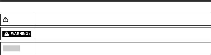
Particularly important information is distinguished in this manual by the following notations:
This is the safety alert symbol. It is used to alert you to potential personal injury hazards. Obey all safety messages that follow this symbol to avoid possible injury or death.
A WARNING indicates a hazardous situation which, if not avoided, could result in death or serious injury.
NOTICE
A NOTICE indicates special precautions that must be taken to avoid damage to the vehicle or other property.
TIP |
A TIP provides key information to make procedures easier or clearer. |
|
|
IMPORTANT MANUAL INFORMATION
EAUW0710
TT-R125(Y) / TT-R125E(Y) /
TT-R125LW(Y) / TT-R125LWE(Y)
OWNER’S MANUAL
© 2008 byYamaha Motor da Amazônia Ltda 1st edition, May 2008
All rights reserved
Any reprinting or unauthorized use without the written permission of Yamaha Motor da Amazônia Ltda is expressly prohibited.
Printed in Brazil.

TABLE OF CONTENTS
SAFETY INFORMATION .................... |
1-1 |
DESCRIPTION ................................... |
2-1 |
Left view (TT-R125 / TT-R125E) ... |
2-1 |
Left view |
|
(TT-R125LW / TT-R125LWE) ..... |
2-2 |
Right view |
|
(TT-R125 / TT-R125E) ................ |
2-3 |
Right view |
|
(TT-R125LW / TT-R125LWE) ..... |
2-4 |
Controls and instruments ............. |
2-5 |
INSTRUMENT AND CONTROL |
|
FUNCTIONS ................................. |
3-1 |
Main switch .................................... |
3-1 |
Handlebar switches ...................... |
3-1 |
Clutch lever ................................... |
3-2 |
Shift pedal ..................................... |
3-2 |
Brake lever .................................... |
3-2 |
Brake pedal ................................... |
3-3 |
Fuel tank cap ................................. |
3-3 |
Fuel ................................................ |
3-3 |
Fuel tank breather hose ............... |
3-5 |
Fuel cock ....................................... |
3-5 |
Starter (choke) knob ..................... |
3-6 |
Kickstarter ...................................... |
3-6 |
Seat ................................................ |
3-6 |
Adjusting the front fork |
|
(TT-R125LWE) ............................ |
3-7 |
Adjusting the shock absorber |
|
assembly .................................... |
3-8 |
Sidestand ....................................... |
3-9 |
Starting circuit cut-off system .... |
3-10 |
FOR YOUR SAFETY |
|
- PRÉ-OPERATION CHECKS ...... |
4-1 |
Pre-operation checks ................... |
4-2 |
OPERATION AND IMPORTANT |
|
RIDING POINTS ............................ |
5-1 |
Starting a cold engine .................. |
5-1 |
Starting a warm engine ................ |
5-2 |
Shifting ........................................... |
5-2 |
Engine break-in ............................ |
5-3 |
Parking .......................................... |
5-4 |
PERIODIC MAINTENANCE AND |
|
ADJUSTMENT.............................. |
6-1 |
Periodic maintenance chart for |
|
the emission control system ..... |
6-2 |
General maintenance and |
|
lubrication chart ......................... |
6-3 |
Removing and installing panels .. |
6-6 |
Checking the spark plug .............. |
6-7 |
Engine oil ...................................... |
6-8 |
Cleaning the air filter element |
|
and check hoses ..................... |
6-10 |
Cleaning the spark arrester ....... |
6-11 |
Adjusting the carburetor ............. |
6-12 |
Adjusting the engine idling |
|
speed ........................................ |
6-12 |
Adjusting the throttle cable |
|
free play .................................... |
6-13 |
Valve clearance .......................... |
6-14 |
Tires ............................................. |
6-14 |
Spoke wheels .............................. |
6-16 |
Adjusting the clutch lever |
|
free play .................................... |
6-16 |
Adjusting the brake lever free |
|
play (TT-R125 / TT-R125E) ...... |
6-17 |
Adjusting the brake lever |
|
free play |
|
(TT-R125LW / TT-R125LWE) ... |
6-17 |
Adjusting the brake pedal |
|
position and free play ............. |
6-18 |
Checking the front brake shoes |
|
(TT-R125 / TT-R125E) .............. |
6-19 |
Checking the front brake pads |
|
(TT-R125LW / TT-R125LWE) |
|
and rear brake shoes .............. |
6-19 |
Checking the front brake fluid |
|
level .......................................... |
6-20 |
Changing the brake fluid ........... |
6-21 |
Drive chain slack ........................ |
6-21 |
Cleaning and lubricating the |
|
drive chain ............................... |
6-22 |
Checking and lubricating the |
|
cables ....................................... |
6-22 |
Checking and lubricating the |
|
throttle grip and cable ............. |
6-23 |
Checking and lubricating the |
|
brake and shift pedals ............ |
6-23 |

TABLE OF CONTENTS
Checking and lubricating the |
|
SPECIFICATIONS .............................. |
8-1 |
brake and clutch levers |
|
|
|
(TT-R125 / TT-R125E) .............. |
6-23 |
CONSUMER INFORMATION ............. |
9-1 |
Checking and lubricating the |
|
Identification numbers .................. |
9-1 |
brake and clutch levers |
|
Key identification number ........... |
9-1 |
(TT-R125LW / TT-R125LWE) ... |
6-24 |
Vehicle identification number ...... |
9-1 |
Checking and lubricating the |
|
Model label .................................... |
9-1 |
sidestand .................................. |
6-24 |
|
|
Checking the front fork ............... |
6-24 |
|
|
Checking the steering ................ |
6-25 |
|
|
Checking the wheel bearings .... |
6-25 |
|
|
Battery .......................................... |
6-26 |
|
|
Replacing the fuse ...................... |
6-27 |
|
|
Supporting the motorcycle ......... |
6-28 |
|
|
Front wheel .................................. |
6-28 |
|
|
To remove the front wheel |
|
|
|
(TT-R125 / TT-R125E) .............. |
6-28 |
|
|
To install the front wheel |
|
|
|
(TT-R125 / TT-R125E) .............. |
6-29 |
|
|
To remove the front wheel |
|
|
|
(TT-R125LW / TT-R125LWE) ... |
6-29 |
|
|
To install the front wheel |
|
|
|
(TT-R125LW / TT-R125LWE) ... |
6-29 |
|
|
Rear wheel .................................. |
6-30 |
|
|
Troubleshooting .......................... |
6-31 |
|
|
Troubleshooting chart ................ |
6-33 |
|
|
MOTORCYCLE CARE AND |
|
|
|
STORAGE ..................................... |
7-1 |
|
|
Care ............................................... |
7-1 |
|
|
Storage .......................................... |
7-3 |
|
|

SAFETY INFORMATION
EAU41214
Be a Responsible Owner
As the vehicle’s owner, you are responsible for the safe and proper operation of your motorcycle.
Motorcycles are single-track vehicles. Their safe use and operation are dependent upon the use of proper riding techniques as well as the expertise of the operator.Every operator should know the following requirements before riding this motorcycle.
He or she should:
zObtain thorough instructions from a competent source on all aspects of motorcycle operation.
zObserve the warnings and maintenance requirements in this Owner’s Manual.
zObtain qualified training in safe and proper riding techniques.
zObtain professional technical service as indicated in this Owner’s Manual and/or when made necessary by mechanical conditions.
Safe Riding
Perform the pre-operation checks each time you use the vehicle to make sure
it is in safe operating condition. Failure to inspect or maintain the vehicle properly increases the possibility of an accident or equipment damage. See page 4-1 for a list of pre-operation checks.
zThis motorcycle is designed for offroad use only, therefore, it is illegal to operate it on public streets, roads, or highways, even a dirt or gravel one. Off-road use on public lands may be illegal. Please check local regulations before riding.
zThis motorcycle is designed to carry the operator only. No passengers.
zThe failure of motorists to detect and recognize motorcycles in traffic is the predominating cause of automobile/motorcycle accidents. Many accidents have been caused by an automobile driver who did not see the motorcycle. Making yourself conspicuous appears to be very effective in reducing the chance of this type of accident.
Therefore:
z Wear a brightly colored jacket.
1 - 1
z Use extra caution when you are approaching and passing through intersections, since intersections
are the most likely places for 1 motorcycle accidents to occur.
zRide where other motorists can see you. Avoid riding in another
motorist’s blind spot.
zMany accidents involve inexperienced operators.
zMake sure that you are qualified and that you only lend your motorcycle to other qualified operators.
zKnow your skills and limits. Staying within your limits may help you to avoid an accident.
zWe recommend that you practice riding your motorcycle
until you have become thoroughly familiar with the motorcycle and all of its controls.
zMany accidents have been caused by error of the motorcycle operator. A typical error made by the operator is veering wide on a turn due to excessive speed or undercornering (insufficient lean angle for the speed). Never travel faster than warranted by conditions.
SAFETY INFORMATION
zRide cautiously in unfamiliar areas. You may encounter hidden obstacles that could cause an
1accident.
zThe posture of the operator is important for proper control. The operator should keep both hands on the handlebar and both feet on the operator footrests during operation to maintain control of the motorcycle.
zNever ride under the influence of alcohol or other drugs.
zBe sure the transmission is in neutral before starting the engine.
Protective apparel
The majority of fatalities from motorcycle accidents are the result of head injuries.The use of a safety helmet is the single most critical factor in the prevention or reduction of head injuries.
zAlways wear an approved helmet.
zWear a face shield or goggles.Wind in your unprotected eyes could contribute to an impairment of vision that could delay seeing a hazard.
zThe use of a jacket, heavy boots,
trousers, gloves, etc., is effective in preventing or reducing abrasions or lacerations.
zNever wear loose-fitting clothes, otherwise they could catch on the control levers, footrests, or wheels and cause injury or an accident.
zAlways wear protective clothing that covers your legs, ankles, and feet.The engine or exhaust system become very hot during or after operation and can cause burns.
Avoid Carbon Monoxide Poisoning
All engine exhaust contains carbon monoxide, a deadly gas. Breathing carbon monoxide can cause headaches, dizziness, drowsiness, nausea, confusion, and eventually death.
Carbon Monoxide is a colorless, odorless, tasteless gas which may be present even if you do not see or smell any engine exhaust. Deadly levels of carbon monoxide can collect rapidly and you can quickly be overcome and unable to save yourself. Also, deadly levels of carbon monoxide can linger for hours or days in enclosed or poorly ventilated areas. If you experience any symptoms
1 - 2
of carbon monoxide poisoning, leave the area immediately, get fresh air, and SEEK MEDICAL TREATMENT.
zDo not run engine indoors. Even if you try to ventilate engine exhaust with fans or open windows and doors, carbon monoxide can rapidly reach dangerous levels.
zDo not run engine in poorly ventilated or partially enclosed areas such as barns, garages, or carports.
zDo not run engine outdoors where engine exhaust can be drawn into a building through openings such as windows and doors.
Loading
Adding accessories to your motorcycle can adversely affect stability and handling if the weight distribution of the motorcycle is changed. To avoid the possibility of an accident, use extreme caution when adding accessories to your motorcycle. Use extra care when riding a motorcycle that has added accessories. Here are some general guidelines to follow if adding accessories to your motorcycle:

SAFETY INFORMATION
Operation of an overloaded vehicle could cause an accident.
zThe weight of the operator must not exceed 150 kg (331 lb).
zAccessory weight should be kept as low and close to the motorcycle as possible. Securely pack your heaviest items as close to the center of the vehicle as possible and make sure to distribute the weight as evenly as possible on both sides of the motorcycle to minimize imbalance or instability.
zShifting weights can create a sudden imbalance. Make sure that accessories are securely attached to the motorcycle before riding.
Check accessory mounts frequently.
zProperly adjust the suspension for your load, and check the condition and pressure of your tires.
zNever attach any large or heavy items to the handlebar, front fork, or front fender.
GenuineYamaha Accessories
Choosing accessories for your vehicle is an important decision. Genuine
Yamaha accessories, which are available only from a Yamaha dealer, have been designed, tested, and approved by Yamaha for use on your vehicle.
Many companies with no connection to Yamaha manufacture parts and accessories or offer other modifications forYamaha vehicles.Yamaha is not in a position to test the products that these aftermarket companies produce. Therefore,Yamaha can neither endorse nor recommend the use of accessories not sold byYamaha or modifications not specifically recommended by Yamaha, even if sold and installed by a Yamaha dealer
Aftermarket Parts, Accessories, and Modifications
While you may find aftermarket products similar in design and quality to genuine Yamaha accessories, recognize that some aftermarket accessories or modifications are not suitable because of potential safety hazards to you or others. Installing aftermarket products or having other modifications performed to your vehicle that change any of the
1 - 3
vehicle’s design or operation characteristics can put you and others at greater risk of serious injury or death.
You are responsible for injuries related 1 to changes in the vehicle.
Keep the following guidelines in mind, as well as those provided under “Loading” when mounting accessories.
zNever install accessories that would impair the performance of your motorcycle. Carefully inspect the accessory before using it to make sure that it does not in any way reduce ground clearance or cornering clearance, limit suspension travel, steering travel or control operation.
zAccessories fitted to the handlebar or the front fork area can create instability due to improper weight distribution. If accessories are added to the handlebar or front fork area, they must be as lightweight as possible and should be kept to a minimum.
zBulky or large accessories may seriously affect the stability of the motorcycle.Wind may attempt to

SAFETY INFORMATION
lift the motorcycle, or the motorcycle may become unstable in cross winds.
1 z Certain accessories can displace the operator from his or her normal riding position.This improper position limits the freedom of movement of the operator and may limit control ability, therefore, such accessories are not recommended.
zUse caution when adding electrical accessories. If electrical accessories exceed the capacity of the motorcycle’s electrical system, an electric failure could result, which could cause a dangerous loss of lights or engine power.
AftermarketTires and Rims
The tires and rims that came with your motorcycle were designed to match the performance capabilities and to provide the best combination of handling, braking, and comfort. Other tires, rims, sizes, and combinations may not be appropriate. Refer to page 6-14 for tire specifications and more information on replacing your tires.
1 - 4
DESCRIPTION
EAU32220
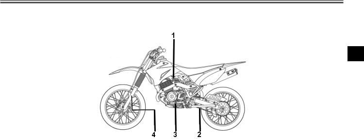
Left view (TT-R125 / TT-R125E)
2
1.Fuel cock (page 3-5)
2.Drive chain (page 6-21)
3.Shift pedal (page 3-2)
4.Front suspension (page 3-7)
2 - 1

DESCRIPTION
Left view (TT-R125LW / TT-R125LWE)
2
1.Fuel cock (page 3-5)
2.Drive chain (page 6-21)
3.Shift pedal (page 3-2)
4.Front suspension (page 3-7)
2 - 2
DESCRIPTION
EAU32230
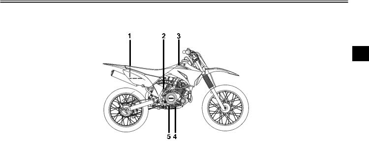
Right view (TT-R125 / TT-R125E)
2
1.Air filter (page 6-10)
2.Kickstarter (page 3-6)
3.Fuel tank (page 3-3)
4.Engine oil dipstick (page 6-8)
5.Rear brake pedal (page 3-3)
2 - 3
DESCRIPTION
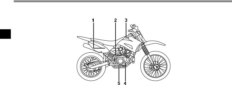
Right view (TT-R125LW / TT-R125LWE)
2
1.Air filter (page 6-10)
2.Kickstarter (page 3-6)
3.Fuel tank (page 3-3)
4.Engine oil dipstick (page 6-8)
5.Rear brake pedal (page 3-3)
2 - 4
DESCRIPTION
EAU10430
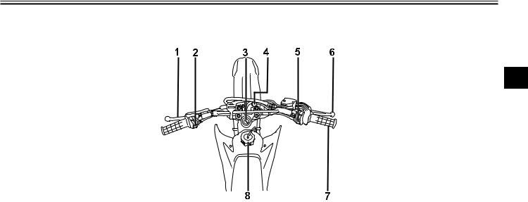
Controls and instruments
2
1.Clutch lever (page 3-2)
2.Engine stop switch (page 3-1)
3.Main switch (page 3-1)
4.Starter (choke) (page 3-6)
5.Start switch (TT-R125E / TT-R125LWE) (page 3-1)
6.Front brake lever (page 3-2)
7.Throttle grip (page 6-13)
8.Fuel tank cap (page 3-3)
2 - 5
INSTRUMENT AND CONTROL FUNCTIONS
EAU40340
Main switch
3
The main switch controls the ignition system. The main switch positions are described below.
EAU10630
ON
All electrical systems are supplied with power, and the engine can be started. The key cannot be removed.
EAU45751
OFF
All electrical systems are off. The key can be removed.
EWA10072
Never turn the key to “OFF” while the vehicle is moving, otherwise the electrical systems will be switched off, which may result in loss of control or an accident.
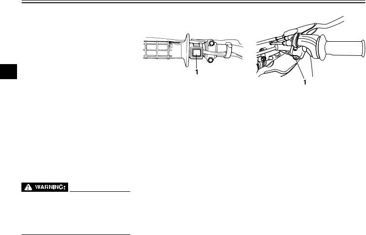
EAU12347
Handlebar switches
1. Engine stop switch
EAU12670
“ENGINE STOP” button
Hold this button pushed until the engine stops in case of an emergency, such as when the vehicle overturns or when the throttle cable is stuck.
1. Start switch
EAU12711
Start switch “ ”
”
Push this switch to crank the engine with the starter. See page 5-1 for starting instructions prior to starting the engine.
3 - 1
INSTRUMENT AND CONTROL FUNCTIONS
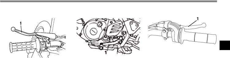
EAU31640
Clutch lever
1. Clutch lever
The clutch lever is located at the left handlebar grip.To disengage the clutch, pull the lever toward the handlebar grip. To engage the clutch, release the lever. The lever should be pulled rapidly and released slowly for smooth clutch operation.
The clutch lever is equipped with a clutch switch, which is part of the starting circuit cut-off system. (See page 3-10.)
EAU12870
Shift pedal
1. Shift pedal
The shift pedal is located on the left side of the engine and is used in combination with the clutch lever when shifting the gears of the 5-speed constant-mesh transmission equipped on this motorcycle.
EAU12890
Brake lever
3
1. Front brake lever
The brake lever is located at the right handlebar grip.To apply the front brake, pull the lever toward the handlebar grip.
3 - 2
INSTRUMENT AND CONTROL FUNCTIONS
EAU12941 |
EAU13182 |
EAU13212 |
Brake pedal |
Fuel tank cap |
Fuel |
3
1. Rear brake pedal
The brake pedal is on the right side of the motorcycle.To apply the rear brake, press down on the brake pedal.
1. Fuel tank cap
To remove the fuel tank cap, turn it counterclockwise, and then pull it off. To install the fuel tank cap, insert it into the tank opening, and then turn it clockwise.
EWA11091
Make sure that the fuel tank cap is properly closed after filling fuel. Leaking fuel is a fire hazard.
1.Fuel tank filler tube
2.Fuel level
Make sure there is sufficient gasoline in the tank.
EWA10881
Gasoline and gasoline vapors are extremely flammable. To avoid fires and explosions and to reduce the risk of injury when refueling, follow these instructions.
1.Before refueling, turn off the engine and be sure that no one is sitting on the vehicle. Never refuel while smoking, or while in the vicinity of sparks, open flames, or other sources of ignition such as the pilot lights of water heaters and clothes dryers.
3 - 3
INSTRUMENT AND CONTROL FUNCTIONS
2.Do not overfill the fuel tank. Stop filling when the fuel reaches the bottom of the filler tube. Because fuel expands when it heats up, heat from the engine or the sun can cause fuel to spill out of the fuel tank.
3. Wipe |
up any spilled fuel |
i m m e d i a t e l y . N O T I C E : |
|
Immediately wipe off spilled |
|
fuel with a clean, dry, soft cloth, |
|
since fuel may deteriorate |
|
painted surfaces or plastic |
|
parts. |
[ECA10071] |
4.Be sure to securely close the fuel tank cap.
EWA15151
Gasoline is poisonous and can cause injury or death. Handle gasoline with care. Never siphon gasoline by mouth. If you should swallow some gasoline or inhale a lot of gasoline vapor, or get some gasoline in your eyes, see your doctor immediately. If gasoline spills on your skin, wash with soap and water. If gasoline spills on your clothing, change your clothes.
EAU44781
For Canada
Recommended fuel:
REGULAR UNLEADED
GASOLINE ONLY Fuel tank capacity:
6.0 L (1.59 US gal, 1.32 Imp.gal) Fuel reserve amount:
0.83 L (0.22 US gal, 0.18 Imp.gal)
ECA11400
NOTICE
Use only unleaded gasoline.The use of leaded gasoline will cause severe damage to internal engine parts, such as the valves and piston rings, as well as to the exhaust system.
YourYamaha engine has been designed to use regular unleaded gasoline with a pump octane number [(R+M)/2] of 86 or higher, or a research octane number of 91 or higher. If knocking (or pinging) occurs, use a gasoline of a different brand or premium unleaded fuel. Use of unleaded fuel will extend spark plug life and reduce maintenance cost.
Gasohol
There are two types of gasohol: gasohol
containing ethanol and that containing methanol. Gasohol containing ethanol can be used if ethanol content does not exceed 10% (E10). Gasohol containing methanol is not recommended by Yamaha because it can cause damage to the fuel system or vehicle
performance problems.
3
For Europe and Oceania
Recommended fuel:
For Europe: REGULAR UNLEADED GASOLINE ONLY
For Oceania: UNLEADED GASOLINE ONLY
Fuel tank capacity:
6.0 L (1.59 US gal, 1.32 Imp.gal) Fuel reserve amount:
0.83 L (0.22 US gal, 0.18 Imp.gal)
ECA11400
NOTICE
Use only unleaded gasoline.The use of leaded gasoline will cause severe damage to internal engine parts, such as the valves and piston rings, as well as to the exhaust system.
YourYamaha engine has been designed to use regular unleaded gasoline with a
3 - 4
INSTRUMENT AND CONTROL FUNCTIONS
research octane number of 91 or higher. |
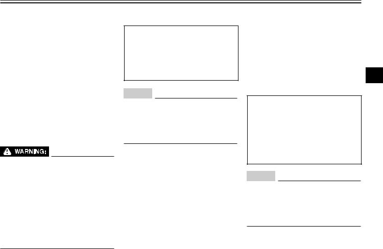
EAU13412 |
EAU13561 |
|
Fuel tank breather hose |
Fuel cock |
||
If knocking (or pinging) occurs, use a |
|||
|
|
||
gasoline of a different brand or premium |
|
|
|
unleaded fuel. Use of unleaded fuel will |
|
|
|
extend spark plug life and reduce |
|
|
|
maintenance costs. |
|
|
3
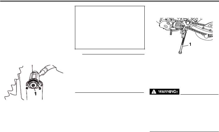
1. Breather hose
Before operating the motorcycle:
zCheck the fuel tank breather hose connection.
zCheck the fuel tank breather hose for cracks or damage, and replace it if damaged.
zMake sure that the fuel tank breather hose is not blocked, and clean it if necessary.
3 - 5
The fuel cock supplies fuel from the tank to the carburetor while filtering it also. The fuel cock has three positions:
OFF
With the lever in this position, fuel will not flow. Always return the lever to this position when the engine is not running.
ON
With the lever in this position, fuel flows to the carburetor. Normal riding is done with the lever in this position.
RES
This indicates reserve. If you run out of fuel while riding, move the lever to this position. Fill the tank at the first opportunity. Be sure to set the lever back to “ON” after refueling!
INSTRUMENT AND CONTROL FUNCTIONS
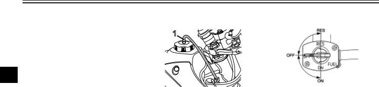
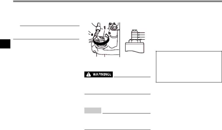
EAU13600
Starter (choke) knob “ ”
”
1. Starter (choke) knob
Starting a cold engine requires a richer air-fuel mixture, which is supplied by the starter (choke).
Move the knob in direction (a) to turn on the starter (choke).
Move the knob in direction (b) to turn off the starter (choke).
EAU13660
Kickstarter
1. Kickstarter
If the engine fails to start by pushing the start switch, try to start it by using the kickstarter. To start the engine, fold out the kickstarter lever, move it down lightly with your foot until the gears engage, and then push it down smoothly but forcefully.This model is equipped with a primary kickstarter, allowing the engine to be started in any gear if the clutch is disengaged. However, shifting the transmission into the neutral position before starting is recommended.
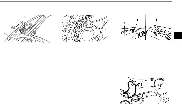
EAUW0480
Seat
3
1.Bolt
2.Panel C
To remove the seat
1.Remove panel A. (See page 6-6.)
2.Remove the bolt.
3.Remove the bolt that fastens the seat and panel C.
4.Remove the seat by pulling it off.
To install the seat
1.Insert the seat into the seat holders as shown.
3 - 6
INSTRUMENT AND CONTROL FUNCTIONS
2.Place the seat in the original position, and then tighten the bolts.
3.Install the panel.
TIP
Make sure that the seat is properly secured before riding.
3
EAU14721
Adjusting the front fork (TT-R125LWE)
1. Adjusting bolt
EWA10180
Always adjust both fork legs equally, otherwise poor handling and loss of stability may result.
This front fork is equipped with spring preload adjusting bolts.
ECA10101
NOTICE
To avoid damaging the mechanism, do not attempt to turn beyond the maximum or minimum settings.
Adjust the spring preload as follows. To increase the spring preload and
thereby harden the suspension, turn the adjusting bolt on each fork leg in direction (a). To decrease the spring preload and thereby soften the suspension, turn the adjusting bolt on each fork leg in direction (b).
Align the appropriate groove on the adjusting mechanism with the top of the front fork cap bolt.
Spring preload setting:
Minimum (soft): 4
Standard:
4
Maximum (hard): 1
3 - 7
INSTRUMENT AND CONTROL FUNCTIONS
EAUW0471
Adjusting the shock absorber assembly
This shock absorber assembly is equipped with a spring preload adjusting nut, a rebound damping force adjusting dial and a compression damping force adjusting knob.
ECA10101
NOTICE
To avoid damaging the mechanism, do not attempt to turn beyond the maximum or minimum settings.
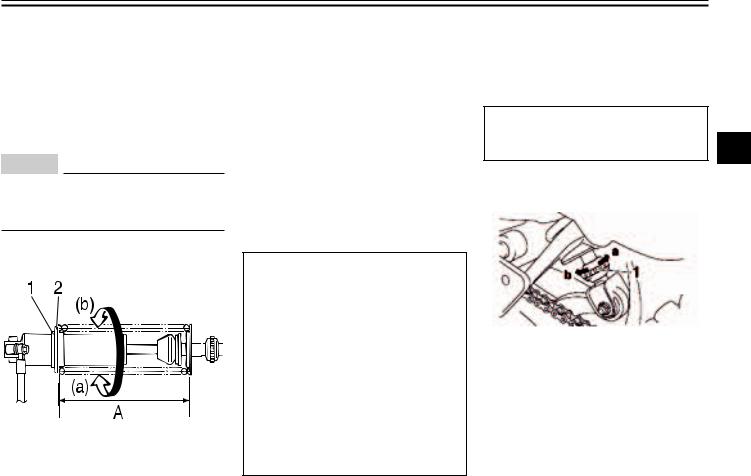
Spring preload
1.Locknut
2.Adjusting nut
1.Loosen the locknut.
2.To increase the spring preload and thereby harden the suspension, turn the adjusting nut in direction
(a).To decrease the spring preload and thereby soften the suspension, turn the adjusting nut in direction
(b).
The spring preload setting is determined by measuring distance A, shown in the illustration. The shorter the distance A is, the higher the spring preload; the longer distance A is, the lower the spring preload.
Spring preload:
Minimum (soft):
TT-R125 / TT-R125E / TT-R125LW Distance A = 175 mm (6.89 in) TT-R125LWE
Distance A = 167.5 mm (6.59 in) Standard:
TT-R125 / TT-R125E / TT-R125LW Distance A = 165 mm (6.50 in) TT-R125LWE
Distance A = 160.5 mm (6.32 in) Maximum (hard):
TT-R125 / TT-R125E / TT-R125LW Distance A = 155 mm (6.10 in) TT-R125LWE
Distance A = 147.5 mm (5.80 in)
3.Tighten the locknut to the specified torque. NOTICE: Always tighten the locknut against the adjusting nut, and then tighten the locknut to the specified torque. [ ECA11241]
Tightening torque: |
|
Locknut: |
3 |
42 Nm (4.2 m.kgf, 30 ft.lbf) |
Rebound damping force (TT-R125LWE)
1. Adjuster
To increase the rebound damping force and thereby harden the rebound damping, turn the adjusting dial in direction (a). To decrease the rebound damping force and thereby soften the rebound damping, turn the adjusting dial in direction (b).
3 - 8
INSTRUMENT AND CONTROL FUNCTIONS
|
|
Rebound damping setting: |
|
|
Minimum (soft): |
|
|
1 clicks in direction (a)* |
|
|
Standard: |
|
|
12 clicks in direction (a)* |
|
|
Maximum (hard): |
|
|
20 clicks in direction (a)* |
|
|
* With the adjusting dial fully turned |
|
||
3 |
|
in direction (b) |
|
|
|
|
|
|
Compression damping force (TT-R125LWE)
1. Adjusting bolt
To increase the compression damping force and thereby harden the compression damping, turn the adjusting knob in direction (a). To decrease the compression damping force and thereby soften the compression damping, turn the adjusting knob in direction (b).
Compression damping setting:
Minimum (soft):
1 clicks in direction (a)* Standard:
9 clicks in direction (a)* Maximum (hard):
12 clicks in direction (a)* * With the adjusting knob fully
turned in direction (b)
TIP
To obtain a precise adjustment, it is advisable to check the actual total number of clicks or turns of each damping force adjusting mechanism. This adjustment range may not exactly match the specifications listed due to small differences in production.
EAU37490
Sidestand
1. Sidestand
The sidestand is located on the left side of the frame. Raise the sidestand or lower it with your foot while holding the vehicle upright.
EWA14190
The vehicle must not be ridden with the sidestand down, or if the sidestand cannot be properly moved up (or does not stay up), otherwise the sidestand could contact the ground and distract the operator, resulting in a possible loss of control.
3 - 9

INSTRUMENT AND CONTROL FUNCTIONS
EAU15391
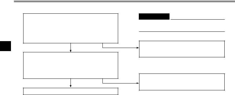
Starting circuit cut-off system
The starting circuit cut-off system (comprising the clutch switch and the neutral switch) prevents starting when the transmission is in gear and the clutch lever is not pulled.
Periodically check the operation of the 3 starting circuit cut-off system according
to the following procedure.
TIP
This check is most reliable if performed with a warmed-up engine.
3 - 1 0
INSTRUMENT AND CONTROL FUNCTIONS
With the engine turned off:
1.Make sure that the engine stop switch is set to “ ”.
”.
2.Turn the key to “ON”.
3.Shift the transmission into the neutral position.
4.Push the start switch.
Does the engine start?
3 |
YES |
NO |
|
5.Turn the engine off.
6.Shift the transmission into gear.
7.Keep the clutch lever pulled.
8.Push the start switch.
Does the engine start?
YES NO
The system is OK. The motorcycle can be ridden.
 WARNING
If a malfunction is noted, have a Yamaha dealer check the system before riding.
The neutral switch may not be working correctly.
The motorcycle should not be ridden until checked by a Yamaha dealer.
The clutch switch may not be working correctly.
The motorcycle should not be ridden until checked by a Yamaha dealer.
3 - 1 1
FORYOUR SAFETY - PRE-OPERATION CHECKS
EAU15595
Inspect your vehicle each time you use it to make sure the vehicle is in safe operating condition. Always follow the inspection and maintenance procedures and schedules described in the Owner’s Manual.
EWA11151
Failure to inspect or maintain the vehicle properly increases the possibility of an accident or equipment damage. Do not operate the vehicle if you find any problem. If a problem cannot be corrected by the procedures provided in this manual, have the vehicle inspected by aYamaha dealer.
Before using this vehicle, check the following points:
4
4 - 1
 Loading...