


MIXING CONSOLE
SERVICE MANUAL
MG06X |
MG06 |
CONTENTS |
|
SPECIFICATIONS ................................ |
3/5 |
PANEL LAYOUT ....................... |
7 |
DIMENSIONS .............................................. |
8 |
CIRCUIT BOARD LAYOUT |
|
................................................. |
8 |
DISASSEMBLY PROCEDURE ............... |
9 |
LSI PIN DESCRIPTIONLSI ............... |
13 |
CIRCUIT BOARDS ......................... |
14 |
INSPECTIONS .............................................. |
17 |
PARTS LIST |
|
BLOCK & LEVEL DIAGRAM |
|
|
|
CIRCUIT DIAGRAM |
|
PA 012112
HAMAMATSU, JAPAN
Copyright (c)Yamaha Corporation. All rights reserved. PDF 
 ’13.10

MG06X/MG06
IMPORTANT NOTICE
This manual has been provided for the use of authorized Yamaha Retailers and their service personnel. It has been assumed that basic service procedures inherent to the industry, and more specifically Yamaha Products, are already known and understood by the users, and have therefore not been restated.
WARNING :
IMPORTANT :
Failure to follow appropriate service and safety procedures when servicing this product may result in personal injury, destruction of expensive components and failure of the product to perform as specified. For these reasons, we advise
all Yamaha product owners that all service required should be performed by an authorized Yamaha Retailer or the appointed service representative.
This presentation or sale of this manual to any individual or firm does not constitute authorization certification, recognition of any applicable technical capabilities, or establish a principal-agent relationship of any form.
The data provided is belived to be accurate and applicable to the unit(s) indicated on the cover. The research engineering, and service departments of Yamaha are continually striving to improve Yamaha products. Modifications are, therefore, inevitable and changes in specification are subject to change without notice or obligation to retrofit. Should any discrepancy appear to exist, please contact the distributorÕs Service Division.
WARNING :
IMPORTANT :
Static discharges can destroy expensive components. Discharge any static electricity your body may have accumulated by grounding yourself to the ground bus in the unit (heavy gauge black wires connect to this bus.)
Turn the unit OFF during disassembly and parts replacement. Recheck all work before you apply power to the unit.
WARNING: This product contains chemicals known to the State of California to cause cancer, or birth defects or other reproductive harm.
DO NOT PLACE SOLDER, ELECTRICAL/ELECTRONIC OR PLASTIC COMPONENTS IN YOUR MOUTH FOR ANY REASON WHAT SO EVER!
Avoid prolonged, unprotected contact between solder and your skin! When soldering, do not inhale solder fumes or expose eyes to solder/ flux vapor!
If you come in contact with solder or components located inside the enclosure of this product, wash your hands before handling food.
 WARNING
Components having special characteristics are marked  and must be replaced with parts having specification equal to those originally installed.

2

MG06X/MG06
 SPECIFICATIONS
 General Specifications
0 dBu = 0.775 Vrms Output impedance of signal generator (Rs) = 150 Ω
All level knobs are nominal if not specified.
Frequency Response |
Input to STEREO OUT |
+0.5 dB/-0.5 dB (20 Hz to 20 kHz), |
|
refer to the nominal output level @ 1 kHz, GAIN knob: Min |
|||
|
|
||
|
|
|
|
Total Harmonic Distortion |
Input to STEREO OUT |
0.01 % @+8 dBu (20 Hz to 20 kHz), GAIN knob: Min |
|
(THD+N) |
0.003 % @+18 dBu (1 kHz), GAIN knob: Min |
||
|
|||
Hum&Noise *1 |
Equivalent Input Noise |
-128 dBu (Mono Input Channel, Rs: 150Ω, GAIN knob: Max) |
|
(20 Hz to 20 kHz) |
Residual Output Noise |
-102 dBu (STEREO OUT, STEREO LEVEL knob: Min) |
|
|
|
|
|
Crosstalk (1 kHz) *2 |
|
-88 dB |
|
|
|
|
|
Input Channels |
|
6 channels: Mono (MIC/LINE): 2, Stereo (LINE): 2 |
|
|
|
|
|
Ouput Channels |
|
STEREO OUT: 2, PHONES: 1 |
|
|
|
|
|
Bus |
|
STEREO: 1 |
|
|
|
|
|
|
PAD |
26 dB |
|
|
|
|
|
|
HPF |
80 Hz, 12 dB/oct |
|
|
|
|
|
Mono Input Channel Function |
EQ HIGH |
Gain: +15 dB/-15 dB, Frequency: 10 kHz shelving |
|
|
|
||
EQ LOW |
Gain: +15 dB/-15 dB, Frequency: 100 Hz shelving |
||
|
|||
|
|
|
|
|
PEAK LED |
LED turns on when post EQ signal reaches 3 dB below clipping |
|
|
(+11 dBu) |
||
|
|
||
|
|
|
|
Level Meter |
Post STEREO LEVEL |
2 x 7-segment LED meter |
|
Knob |
[PEAK (+11), +6, +3, 0, -3, -10, -20 dB] |
||
|
|||
|
|
|
|
Internal Digital Effect (MG06X) |
SPX Algorithm |
6 programs |
|
|
|
|
|
Phantom Power Voltage |
|
+48 V |
|
|
|
|
|
Power Supply Adaptor |
|
PA-130 (DC12 V/1.0 A, Cable length = 1.8 m), 120 V, 60 Hz, or |
|
|
MU18 (DC12 V/1.5 A, Cable length = 1.5 m), 100 V-240 V, |
||
|
|
50 Hz/60 Hz, or an equivalent recommended by Yamaha |
|
|
|
|
|
Power Consumption |
|
12 W |
|
|
|
|
|
Dimensions (W×H×D) |
|
149 mm×62 mm×202 mm (5.9"x 2.4"x 7.9") |
|
|
|
|
|
Net Weight |
|
MG06: 0.9 kg (2.0 lbs), MG06X: 0.9 kg (2.0 lbs) |
|
|
|
|
|
Optional Accessory |
|
Mic Stand Adaptor: BMS-10A |
|
|
|
|
|
Included Accessory |
|
AC power adaptor, Owner’s Manual, Technical Specifications |
|
|
|
|
|
Operating Temperature |
|
0 to +40°C |
*1 Noise is measured with A-weighting filter. *2 Crosstalk is measured with 1 kHz band pass filter.
 Analog Input Characteristics
|
PAD |
GAIN |
Actual |
For Use |
|
Input level |
|
|
|
Input Jacks |
Load |
With |
|
|
Max. before |
Connector |
|||
26 dB |
Trim |
Sensitivity *1 |
Nominal |
||||||
|
Impedance |
Nominal |
clip |
|
|||||
|
|
|
|
|
|
||||
|
|
|
|
|
|
|
|
|
|
|
|
+64 dB |
|
|
-72 dBu |
-60 dBu |
-46 dBu |
|
|
|
|
|
|
(0.195 mV) |
(0.775 mV) |
(3.884 mV) |
|
||
|
OFF |
|
|
|
|
||||
|
|
|
|
|
|
|
|
||
|
+20 dB |
|
|
-28 dBu |
-16 dBu |
-2 dBu |
|
||
|
|
|
|
|
|||||
|
|
|
50-6001 |
(30.85 mV) |
(122.8 mV) |
(615.6 mV) |
Combo jack*2 |
||
MIC/LINE 1/L,2/R |
|
|
3 kΩ |
||||||
|
|
Mics/Lines |
|
|
|
(Balanced) |
|||
|
+38 dB |
-46 dBu |
-34 dBu |
-20 dBu |
|||||
|
|
|
|
||||||
|
|
|
|
(3.884 mV) |
(15.46 mV) |
(77.50 mV) |
|
||
|
ON |
|
|
|
|
||||
|
|
|
|
|
|
|
|
||
|
-6 dB |
|
|
-2 dBu |
+10 dBu |
+24 dBu |
|
||
|
|
|
|
|
|||||
|
|
|
|
(615.6 mV) |
(2.451 V) |
(12.28 V) |
|
||
|
|
|
|
|
|
||||
|
|
|
|
|
|
|
|
|
|
LINE 3/4, 5/6 |
- |
- |
10 kΩ |
600 Ω Lines |
-22 dBu |
-10 dBu |
+4 dBu |
Phone jack*3 |
|
(61.56 mV) |
(245.1 mV) |
(1.228 V) |
(Unbalanced) |
||||||
|
|
|
|
|
|||||
|
|
|
|
|
|
|
|
|
3

MG06X/MG06
 Analog Output Characteristics
Output Jacks |
Actual Source |
For Use With |
Output level |
Connector |
||
Impedance |
Nominal |
Nominal |
Max. before clip |
|||
|
|
|||||
|
|
|
|
|
|
|
|
|
|
+4 dBu |
+18 dBu |
XLR-3-32 *4 |
|
STEREO OUT L, R |
75 Ω |
10 kΩ Lines |
Phone jack *5 |
|||
(1.228 V) |
(6.156 V) |
|||||
|
|
|
(Balanced) |
|||
|
|
|
|
|
||
|
|
|
|
|
|
|
PHONES |
33 Ω |
40 Ω Lines |
2.4 mW + 2.4 mW |
24 mW + 24 mW |
Stereo phone jack |
|
|
|
|
|
|
|
|
0dBu is referenced to 0.775Vrms.
*1 Sensitivity is the lowest level that will produce an output of +4 dBu (1.228 V) or the nominal output level when the unit is set to maximum gain. (All level knobs are at their maximum position.)
*2 1&Sleeve = Ground, 2&Tip = Hot, 3&Ring = Cold *3 Tip = Signal, Sleeve = Ground
*4 1= Ground, 2 = Hot, 3 = Cold
*5 Tip = Hot, Ring = Cold, Sleeve = Ground
 JACK LIST (Pin Alignment)
Input and Output Jacks |
Polarities |
Balanced/Unbalanced |
Configurations |
|
|
Pin 1: Ground |
|
XLR connector |
|
MIC/LINE 1/L, 2/R |
|
|
|
|
Pin 2: Hot (+) |
Balanced |
|
|
|
STEREO OUT L, R |
|
|
||
Pin 3: Cold (-) |
|
INPUT |
OUTPUT |
|
MIC/LINE 1/L, 2/R* |
Tip: Hot (+) |
|
TRS phone plug |
|
Ring: Cold (-) |
Balanced |
|
|
|
STEREO OUT L, R* |
|
Ring |
||
Sleeve: Ground |
|
|
||
PHONES |
Tip: L |
|
|
|
Ring: R |
— |
Sleeve |
Tip |
|
|
Sleeve: Ground |
|
||
|
|
|
|
|
|
|
|
TS phone plug |
|
LINE 3/4, 5/6 |
Tip: Signal |
Unbalanced |
|
|
Sleeve: Ground |
|
|
||
|
|
|
|
|
|
|
|
Sleeve |
Tip |
* These jacks also accept connection to TS phone plugs. If you use TS phone plugs, the connection will be unbalanced.
4

MG06X/MG06


0 dBu = 0.775 Vrms :150 Ω
|
→ STEREO OUT |
+0.5 dB/-0.5 dB 20 Hz ̃ 20 kHz |
|
|
|
refer to the nominal output level@1 kHz GAIN |
|
(THD+N) |
→ STEREO OUT |
0.01 % @+8 dBu 20 Hz ̃ 20 kHz |
|
GAIN 0.003 % @+18 dBu 1 kHz GAIN |
|||
|
|
||
|
|
|
|
& *1 (20 Hz 20 kHz) |
|
-128 dBu Rs:150 Ω GAIN |
|
|
-102 dBu STEREO OUT STEREO LEVEL |
||
|
|||
(1 kHz) *2 |
|
-88 dB |
|
|
|
|
|
|
|
6 MIC/LINE 2 LINE 2 |
|
|
|
|
|
|
|
STEREO OUT 2 PHONES 1 |
|
|
|
|
|
|
|
STEREO 1 |
|
|
|
|
|
|
PAD |
26 dB |
|
|
|
|
|
|
HPF |
80 Hz 12 dB/oct |
|
|
|
|
|
|
EQ HIGH HIGH |
+15 dB/-15 dB 10 kHz |
|
|
|
||
EQ LOW LOW |
+15 dB/-15 dB 100 Hz |
||
|
|||
|
|
|
|
|
PEAK LED |
+11 dBu 3 dB |
|
|
|
||
|
|
||
|
|
|
|
|
STEREO LEVEL |
2×7 LED |
|
|
|
PEAK +11 +6 +3 0 -3 -10 -20 dB |
|
(MG06X) |
SPX |
6 |
|
|
|
|
|
|
|
+48 V |
|
|
|
|
|
|
|
MU18 DC12V/1.5A =1.5m |
|
|
100V-240V 50Hz/60Hz |
||
|
|
||
|
|
|
|
|
|
12 W |
|
|
|
|
|
× × |
|
149 mm×62 mm×202 mm |
|
|
|
|
|
|
|
MG06 0.9 kg MG06X 0.9 kg |
|
|
|
|
|
( ) |
|
BMS-10A |
|
|
|
|
|
|
|
Technical Specifications |
|
|
|
|
|
|
|
0 to +40 |
|
|
|
|
*1: A-weighting *2:1 kHz

|
PAD |
|
|
|
|
|
|
|
|
|
|
|
|
|
|
||||
*1 |
|
|
|||||||
|
26 dB |
|
|
|
|
|
|||
|
|
|
|
|
|
|
|
||
|
|
|
|
|
|
|
|
|
|
|
|
+64 dB |
|
|
-72 dBu |
-60 dBu |
-46 dBu |
|
|
|
|
|
|
(0.195 mV) |
(0.775 mV) |
(3.884 mV) |
|
||
|
OFF |
|
|
|
|
||||
|
|
|
|
|
|
|
|
||
|
+20 dB |
|
|
-28 dBu |
-16 dBu |
-2 dBu |
|
||
|
|
|
|
|
|||||
|
|
|
50-600 Ω |
(30.85 mV) |
(122.8 mV) |
(615.6 mV) |
*2 |
||
MIC/LINE 1/L,2/R |
|
|
3 kΩ |
||||||
|
+38 dB |
Mics/Lines |
-46 dBu |
-34 dBu |
-20 dBu |
( ) |
|||
|
|
|
|||||||
|
|
|
|
(3.884 mV) |
(15.46 mV) |
(77.50 mV) |
|
||
|
ON |
|
|
|
|
||||
|
|
|
|
|
|
|
|
||
|
-6 dB |
|
|
-2 dBu |
+10 dBu |
+24 dBu |
|
||
|
|
|
|
|
|||||
|
|
|
|
(615.6 mV) |
(2.451 V) |
(12.28 V) |
|
||
|
|
|
|
|
|
||||
|
|
|
|
|
|
|
|
|
|
LINE 3/4, 5/6 |
- |
- |
10 kΩ |
600 Ω Lines |
-22 dBu |
-10 dBu |
+4 dBu |
*3 |
|
(61.56 mV) |
(245.1 mV) |
(1.228 V) |
( ) |
||||||
|
|
|
|
|
|||||
|
|
|
|
|
|
|
|
|
5

MG06X/MG06

|
|
|
|
|
||
|
|
|
|
|||
|
|
|||||
|
|
|
|
|||
|
|
|
+4 dBu |
+18 dBu |
XLR-3-32 *4 |
|
STEREO OUT L, R |
75 Ω |
10 kΩ Lines |
*5 |
|||
(1.228 V) |
(6.156 V) |
|||||
|
|
|
( ) |
|||
|
|
|
|
|
||
|
|
|
|
|
|
|
PHONES |
33 Ω |
40 Ω Lines |
2.4 mW + 2.4 mW |
24 mW + 24 mW |
|
|
|
|
|
|
|
|
|
0 dBu = 0.775 Vrms
*1 +4 dB (1.228 V) ( ) *2 & = & = & =
*3 = =
*4 = = =
*5 = = =
|
|
|
|
|
|
|
|
/ |
|
|
|
|
1: |
|
XLR |
|
|
MIC/LINE 1/L 2/R |
|
|
|
||
2: |
|
|
|
||
STEREO OUT L R |
INPUT |
OUTPUT |
|||
3: |
|
||||
|
|
||||
|
|
|
|
||
MIC/LINE 1/L 2/R* |
: + |
|
TRS |
|
|
: |
|
|
|||
STEREO OUT L R* |
|
||||
: |
|
||||
|
|
|
|
||
|
: L |
|
|
|
|
PHONES |
: R |
|
|
|
|
|
: |
|
|
|
|
|
|
|
TS |
|
|
LINE 3/4 5/6 |
: |
|
|
|
|
: |
|
|
|||
|
|
|
|
||
|
|
|
|||
* TS |
|
|
|
||
6
MG06X/MG06
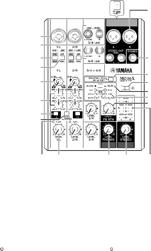
 PANEL LAYOUT
|
|
|
|
|
||||||
q DC IN [12V] jack |
|
q DC IN [12V] |
|
|||||||
w MIC/LINE] mono input jacks (channels 1/L, 2/R) |
w [MIC/LINE] 1/L 2/R |
|||||||||
e [LINE] stereo input jacks (channels 3/4, 5/6) |
e [LINE] ( 3/4 5/6) |
|||||||||
r [PAD] switches |
|
r [PAD] |
|
|||||||
t [HPF] (High-Pass Filter) switches |
|
t [HPF]( ) |
||||||||
y [STEREO OUT] output jacks |
|
y [STEREO OUT] |
|
|||||||
u [PHONES] output jack |
|
u [PHONES] |
|
|||||||
i [GAIN] knobs |
|
i [GAIN] |
|
|||||||
o Equalizer (EQ) knobs |
|
o (EQ) |
|
|||||||
!0 [FX] switches (MG06X) |
|
!0 [FX] (MG06X) |
|
|||||||
!1—[MONO/_STEREO] switch |
|
!1—[MONO _STEREO] |
||||||||
!2 [PEAK] LED |
|
!2 [PEAK] LED |
|
|||||||
!3 [LEVEL] knobs |
|
!3 [LEVEL] |
|
|||||||
!4 [PHONES LEVEL] knob |
|
!4 [PHONES LEVEL] |
|
|||||||
!5 [STEREO LEVEL] knob |
|
!5 [STEREO LEVEL] |
|
|||||||
!6 [PHANTOM +48V] switch/LED |
|
!6 [PHANTOM +48V] /LED |
||||||||
!7[ |
|
|
] (On/Standby) switch |
|
!7 |
|
|
[ ]( / ) |
||
|
|
|
|
|
||||||
|
|
|
|
|
||||||
!8 [REVERB—/_DELAY] switch (MG06X) |
!8 [REVERB— _DELAY] (MG06X) |
|||||||||
!9 Effect select slide switch (MG06X) |
|
!9 (MG06X) |
||||||||
@0 [FX RTN LEVEL] (effect return level) knob (MG06X) |
@0[FX RTN LEVEL] ( ) (MG06X) |
|||||||||
@1 Level meter |
|
@1 |
|
|||||||
7
MG06X/MG06
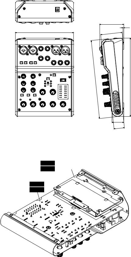
 DIMENSIONS
149 |
This figure shows the MG06X. |
MG06X |
Unit: mm
62 |
2 |
56 |
201 |
202 |
|
30 |
28 |
 CIRCUIT BOARD LAYOUT
(MG06X) PS6X PS-USB assembly
(MG06) PS6 PS-USBAss'y
(MG06X) |
AM6X |
(MG06) |
AM6 |
This figure shows the MG06X.
MG06X
8

MG06X/MG06
 DISASSEMBLY PROCEDURE
1.BOTTOM COVER
(Time required: About 2 minutes)
1-1. Remove the seven (7) screws marked [250]. The bottom cover can then be removed. (Fig. 1)
*When installing the bottom cover, make sure the hook is firmly inserted (6 place). (Fig. 1)
*Tighten the screws marked [250] in the order of a - e. (Fig. 1)
1.2
1-1. [250] 7
1
6
1
[250] a e
( 1)
2.SIDE COVER, SIDE PAD ASSEMBLY(L/R)
(Time required: About 3 minutes each)
2-1. Remove the bottom cover. (See procedure 1.) 2-2. SIDE COVER (L), SIDE PAD ASSEMBLY (L)
2-2-1. Remove the two (2) screws marked [220] and the screw marked [160A]. The side cover (L) can then be removed together with the side pad assembly (L). (Fig. 1)
*When installing the Side cover (L), tighten the screws in the order of f - h as shown in Fig. 1. (Fig. 1)
2-3. SIDE COVER (R), SIDE PAD ASSEMBLY (R)
2-3-1. Remove the two (2) screws marked [210] and the screw marked [160B]. The side cover (R) can then be removed together with the side pad assembly (R). (Fig. 1)
*When installing the Side cover (R), tighten the screws in the order of f - h as shown in Fig. 1.
2. Ass'y L,R3
2-1. 1
2-2. L Ass'y L
2-2-1. [220] 2 [160A] 1Ass'y L L1
L 1 f h 1
2-3. Ass'y R R
2-3-1. [210] 2 [160B] 1Ass'y R R1
R 1 f h 1
 Rear view
This figure shows the MG06X.
MG06X
 Top view
[160B] |
[160A] |
[160C]


 [160C]
 Bottom view
Side cover & Side pad assembly (L) |
|
Side cover & Side pad assembly (R) |
|
|
|
|
|
|
|
|
|
||||
Ass'y |
|
Ass'y |
[250] |
[250] |
[250] |
||||||||||
|
|
|
|
|
|
|
|
|
|
|
|
|
|
|
|
|
|
|
|
|
|
|
|
|
|
|
|
|
|
|
|
|
|
|
|
|
|
|
|
|
|
|
|
|
|
|
|
|
|
|
|
|
|
|
|
|
|
|
|
|
|
|
|
|
|
|
|
|
|
|
|
|
|
|
|
|
|
|
|
|
|
|
|
|
|
|
|
|
|
|
|
|
|
|
|
|
|
|
|
|
|
|
|
|
|
|
|
|
|
|
|
|
|
|
|
|
|
|
|
|
|
|
|
|
|
|
|
|
|
|
|
|
|
|
|
|
|
|
|
|
|
|
|
Hook
Bottom cover
[220] |
[210] |
[250]
Hook
[250]
Hook
[250]
Fig. 1 1
9
MG06X/MG06
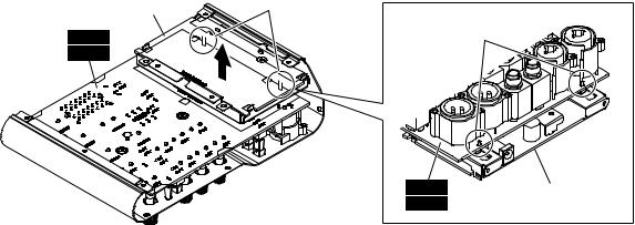
3.PS-USB ASSEMBLY
(Time required: About 5 minutes)
3-1. Remove the bottom cover. (See procedure 1.)
3-2. Remove the side cover (L/R) and the side pad assembly (L/R). (See procedure 2.)
3-3. Remove the two (2) screws marked [160C]. The PS-USB assembly can then be pulled out from the AM6X circuit board (MG06X) or AM6 circuit board (MG06).
(Fig. 1, Fig. 2)
*When installing the PS-USB assembly, insert the two (2) projections of the PS-USB ASSEMBLY to the AM6X circuit board (MG06X) or AM6 circuit board (MG06). (Fig. 2)
|
PS-USB assembly |
Projections |
|
PS-USBAss'y |
|
(MG06X) |
AM6X |
|
(MG06) |
AM6 |
|
3.PS-USB Ass'y 5
3-1. 1
3-2. L,R Ass'y L,R
2
3-3. [160C] 2 AM6X (MG06X)AM6 (MG06) PS-USB Ass'y
1 2
PS-USB Ass'y 2
AM6X MG06X AM6 MG06
2
Projections


|
|
|
AM6X (MG06X) |
PS-USB assembly |
|
This figure shows the MG06X. |
AM6 (MG06) |
PS-USBAss'y |
|
|
MG06X |
|
|
|
|
|
Fig. 2 2 |
|
|
4. |
AM6X Circuit Board (MG06X) / |
4. |
AM6X MG06X AM6 |
|
|
AM6 Circuit Board (MG06) |
|
MG06 12 |
|
|
(Time required: About 12 minutes) |
4-1. |
1 |
|
4-1. |
Remove the bottom cover. (See procedure 1.) |
4-2. |
Ass'y L,R |
|
4-2. Remove the side cover and the side pad assembly (L/R). |
2 |
|
||
|
(See procedure 2.) |
4-3. |
MG06X : |
|
4-3. |
MG06X : |
|
[270] VR 2 [280] VR 4 |
|
|
Remove the two (2) KNOB VR SMALL WHITE/ |
|
[290] LEVEL6 [300] LEVEL1 |
|
|
BLACKs marked [270], four (4) KNOB VR SMALL |
|
3 |
|
|
GREEN/BLACKs marked [280], six (6) KNOB |
|
MG06 : |
|
|
LEVEL WHITE/BLACKs marked [290] and the |
|
[270] VR 2 [280] VR 4 |
|
|
KNOB LEVEL RED/BLACKs marked [300]. (Fig. 3) |
|
[290] LEVEL5 [300] LEVEL1 |
|
|
MG06 : |
|
3 |
|
|
Remove the two (2) KNOB VR SMALL WHITE/ |
4-4. |
[160C] 2 [150] 8 [A] |
|
|
BLACKs marked [270], four (4) KNOB VR SMALL |
|
7 3 |
|
|
GREEN/BLACKs marked [280], five (5) KNOB |
|
|
|
|
LEVEL WHITE/BLACKs marked [290] and the |
|
|
|
|
KNOB LEVEL RED/BLACKs marked [300]. (Fig. 3) |
|
|
|
4-4. |
Remove the two (2) screws marked [160C], eight (8) |
|
|
|
|
screws marked [150] and seven (7) each hexagonal |
|
|
|
|
nuts and washers marked [A]. (Fig. 3) |
|
|
|
10
MG06X/MG06
Top view |
|
|
|
[150] |
[150] |
[A] |
|
|
[270] |
|
|
[280] |
|
|
[290] |
|
|
MG06X: x6 |
|
|
MG06: |
x5 |
|
[300] |
|
|
 Rear view
[160C] |
[160C] |
This figure shows the MG06X.
MG06X
[270]: KNOB VR SMALL WHITE/BLACK VR
[280]: KNOB VR SMALL GREEN/BLACK VR
[290]: KNOB LEVEL WHITE/BLACK LEVEL
[300]: KNOB LEVEL RED/BLACK LEVEL
Fig. 3 3
4-5. |
Reverse the unit and remove the two (2) screws marked |
4-5. |
[30] 2 PS-USB |
|
[30]. The AM6X circuit board (MG06X) or AM6 circuit |
|
Ass'y AM6X MG06X AM6 |
|
board (MG06) can then be removed together with the |
|
MG06 4 |
|
PS-USB ASSEMBLY. (Fig. 4) |
4-6. |
AM6X MG06X AM6 MG06 |
4-6. |
Separate the PS-USB ASSEMBLY from the AM6X |
|
PS-USB Ass'y |
|
circuit board (MG06X) or AM6 circuit board (MG06). |
|
|
PS-USB assembly
PS-USBAss'y 

[30]
(MG06X) AM6X
(MG06) AM6
This figure shows the MG06X.
MG06X
Fig. 4 4
11
MG06X/MG06
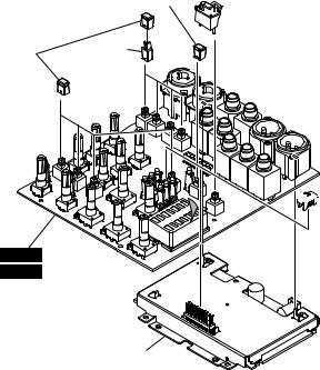
4-7. MG06X :
Remove the four (4) knob joint HPF BLACKs marked [40], eight (8) push button HPF D-GRAY/WHITEs marked [50], the push button HPF RED marked [60], the push button PFL MILKY/D-GRAY marked [70] and the knob slide switch BLUE marked [80] from the AM6X circuit board. (Fig. 5)
MG06 :
Remove the four (4) knob joint HPF BLACKs marked [40], five (5) push button HPF D-GRAY/WHITEs marked [50], the push button HPF RED marked [60] and the push button PFL MILKY/D-GRAY marked [70] from the AM6 circuit board. (Fig. 5)
*The knob joint HPF BLACK marked [40], the push button HPF D-GRAY/WHITE marked [50], the push button HPF RED marked [60], the push button PFL MILKY/D-GRAY marked [70] and the knob slide switch BLUE marked [80] (AM6X circuit board only) are not components of the AM6X circuit board (MG06X) or AM6 circuit board (MG06).
*When replacing the AM6X circuit board (MG06X) or AM6 circuit board (MG06), remove the knob joint HPF BLACK marked [40], the push button HPF D-GRAY/ WHITE marked [50], the push button HPF RED marked [60], the push button PFL MILKY/D-GRAY marked [70] and the knob slide switch BLUE marked [80] (AM6X circuit board only) and install them on the new circuit board.
This figure shows the MG06X. |
[60] |
|
|
MG06X |
|
[50] |
[40] |
|
|
MG06X: x8 |
|
MG06: x5 |
|
AM6X (MG06X)
AM6 (MG06)
PS-USB assembly
PS-USBAss'y
4-7. MG06X :
AM6X [40] HPF4 [50]HPF8 [60] HPF RED1
[70] PFL1 [80]1 5
MG06 :
AM6 [40] HPF4 [50]HPF5 [60] HPF RED1
[70]PFL1 5
[40] HPF [50] HPF [60]
HPF RED [70] PFL [80]
AM6X AM6X MG06X
AM6 MG06
AM6X MG06X AM6 MG06
[40] HPF [50]
HPF [60] HPF RED [70] PFL
[80]AM6X
[40]: KNOB JOINT HPF BLACK HPF


 [70]
[70]
[50]: PUSH BUTTON HPF D-GRAY/WHITE HPF
[60]: PUSH BUTTON HPF RED HPF RED
[70]: PUSH BUTTON PFL MILKY/D-GRAY PFL
[80]: KNOB SLIDE SWITCH BLUE


 [80]
[80]
MG06X only
Fig. 5 5
12

MG06X/MG06
 LSI PIN DESCRIPTIONLSI
PCM1780DBQR (X7356A01) DAC (Digital to Analog Converter) |
PS6X: IC905 |
||||||||
PIN |
NAME |
I/O |
FUNCTION |
PIN |
NAME |
I/O |
|
FUNCTION |
|
NO. |
NO. |
|
|
||||||
|
|
|
|
|
|
|
|
||
|
|
|
|
|
|
|
|
|
|
1 |
ZEROL/NA |
O |
Zero flag output for L-channel / No assign |
9 |
NC |
– |
|
No connection |
|
2 |
MS |
I |
Mode control select input |
10 |
NC |
– |
|
No connection |
|
3 |
MC |
I |
Mode control clock input |
11 |
VCC |
– |
|
Power supply, 5-V |
|
4 |
MD |
I |
Mode control data input |
12 |
AGND |
– |
|
Ground |
|
5 |
SCK |
I |
System clock input |
13 |
VCOM |
– |
|
Common voltage decoupling |
|
6 |
DATA |
I |
Audio data digital input |
14 |
VOUTR |
O |
|
Analog output for R-channel |
|
7 |
BCK |
I |
Audio data bit clock input |
15 |
VOUTL |
O |
|
Analog output for L-channel |
|
8 |
LRCK |
I |
Audio data left and right clock input |
16 |
ZEROR/ZEROA |
O |
|
Zero flag output for R-channel / Zero flag output for L- and R-channels |
|
|
|
|
|
|
|
|
|
|
|
PCM1803DBR (X7357A00) ADC (Analog to Digital Converter) |
|
|
|||||||
PCM1803ADBR (X7357B00) ADC (Analog to Digital Converter) |
PS6X: IC904 |
||||||||
|
|
|
|
|
|
|
|
|
|
PIN |
NAME |
I/O |
FUNCTION |
PIN |
NAME |
I/O |
|
FUNCTION |
|
NO. |
NO. |
|
|
||||||
|
|
|
|
|
|
|
|
||
|
|
|
|
|
|
|
|
|
|
1 |
VINL |
I |
Analog input (L ch) |
11 |
BCK |
I/O |
|
Audio data bit clock input/output |
|
2 |
VINR |
I |
Analog input (R ch) |
12 |
DOUT |
O |
|
Audio data digital output |
|
3 |
VREF1 |
- |
Reference-voltage-1 decoupling capacitor |
13 |
DGND |
- |
|
Digital ground |
|
4 |
VREF2 |
- |
Reference-voltage-2 decoupling capacitor |
14 |
VDD |
- |
|
Digital power supply +3.3V |
|
5 |
VCC |
- |
Analog power supply +5V |
15 |
SCKI |
I |
|
System clock input |
|
6 |
AGND |
- |
Analog ground |
16 |
OSR |
I |
|
Oversampling ratio select input |
|
7 |
PDWN |
I |
Power-down control, active-low |
17 |
FMT0 |
I |
|
Audio data format select input 0 |
|
8 |
BYPAS |
I |
HPF bypass control |
18 |
FMT1 |
I |
|
Audio data format select input 1 |
|
9 |
TEST |
I |
Test, must be connected to DGND |
19 |
MODE0 |
I |
|
Mode select input 0 |
|
10 |
LRCK |
I/O |
Audio data latch enable input/output |
20 |
MODE1 |
I |
|
Mode select input 1 |
|
BU6945K-E2 (X9788A00) SSPO |
|
|
|
PS6X: IC902 |
||||
PIN |
NAME |
I/O |
FUNCTION |
PIN |
NAME |
I/O |
FUNCTION |
|
NO. |
NO. |
|||||||
|
|
|
|
|
|
|||
1 |
TYPE3 |
Ish* |
Effect Type Select |
17 |
RTEST2 |
Ish* |
Test (for Supplier) |
|
2 |
TYPE2 |
Ish* |
Effect Type Select |
18 |
RTEST1 |
Ish* |
Test (for Supplier) |
|
3 |
TYPE1 |
Ish* |
Effect Type Select |
19 |
RTEST0 |
Ish* |
Test (for Supplier) |
|
4 |
GND |
– |
Ground |
20 |
GND |
– |
Ground |
|
5 |
IOVDD |
– |
I/O |
21 |
IOVDD |
– |
I/O Power Supply |
|
6 |
TYPE0 |
Ish* |
Power Supply |
22 |
PRST |
Ish+* |
Parameter Fixation Mode Setting (PRST: Hi) |
|
7 |
EFSWN |
Ish+* |
Effect Type Select |
23 |
SDO |
O |
Audio Serial Data Output |
|
8 |
LED |
O |
Effect Switch (H û L detect) |
24 |
SDI |
I |
Audio Serial Data Input (L ch), Parameter Input (R ch) |
|
9 |
FOOT |
Ish+* |
Effect ON/OFF Status (ON: Hi/OFF: Lo) |
25 |
WCLK |
O |
Word Clock Output |
|
10 |
MUTE |
O |
Effect Switch (L û H detect) |
26 |
BCLK |
O |
Bit Clock Output |
|
11 |
THRU |
Ish-* |
Mute (MUTE ON: Hi/MUTE OFF: Lo) |
27 |
SCLK |
O |
System Clock Output |
|
12 |
GND |
– |
Effect Through Setting (THRU: Hi) |
28 |
GND |
– |
Ground |
|
13 |
YTEST |
Ish* |
Ground Test (for Yamaha) |
29 |
XI |
I |
Crystal Oscillator Input |
|
14 |
TVAR |
Ish-* |
Effect Type Variation Select (TVAR: Hi) |
30 |
XO |
O |
Crystal Oscillator Output |
|
15 |
DVDD |
– |
Logic Core Power Supply Input |
31 |
ICN |
Ish* |
Reset |
|
16 |
REG18 |
O |
Built -in Regulator Output |
32 |
CKDIV |
Ish+* |
Input Clock Select (16.93MHz Input: Lo/33.87 MHz Input: Hi) |
|
*Ish: Schmitt Trigger Input
Ish+: Schmitt Trigger Input with pull-up Ish-: Schmitt Trigger Input with pull down
13

MG06X/MG06
 CIRCUIT BOARDS
AM6X (MG06X) / AM6 (MG06) Circuit Board (YF133C0)................................................... |
14/15 |
PS6X (MG06X) / PS6 (MG06) Circuit Board (YF134D0) ........................................................ |
16 |
Note: See parts list for details of circuit board component parts.
: |
|
AM6X (MG06X) / AM6 (MG06) Circuit Board |
|
|
Component side |
14 |
2NA-ZG18490 |
1 |
|
|
 Loading...