


MAJESTY
Table of contents
 Loading...
LIT-11626-20-31 5RU-28199-12
YP400W
OWNER’S MANUAL

EAU10041

INTRODUCTION
EAU10090
Congratulations on your purchase of the Yamaha YP400W. This model is the result of Yamaha’s vast experience in the pro-
duction of fine sporting, touring, and pacesetting racing machines. It represents the high degree of craftsmanship and reli-
ability that have made Yamaha a leader in these fields.
This manual will give you an understanding of the operation, inspection, and basic maintenance of this scooter. If you have
any questions concerning the operation or maintenance of your scooter, please consult a Yamaha dealer.
The design and manufacture of this Yamaha scooter fully comply with the emissions standards for clean air applicable at the
date of manufacture. Yamaha has met these standards without reducing the performance or economy of operation of the
scooter. To maintain these high standards, it is important that you and your Yamaha dealer pay close attention to the rec-
ommended maintenance schedules and operating instructions contained within this manual.
IMPORTANT MANUAL INFORMATION
EAU35821
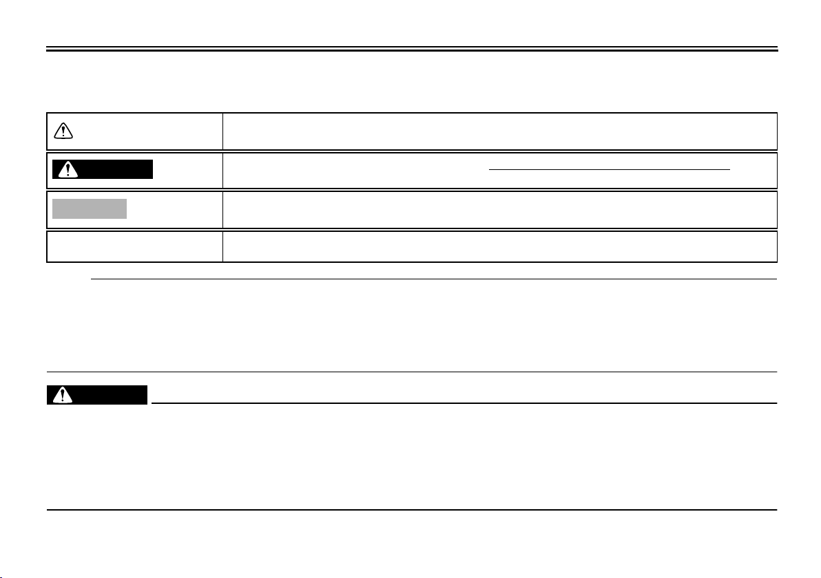
Particularly important information is distinguished in this manual by the following notations:
NOTE:
●
This manual should be considered a permanent part of this scooter and should remain with it even if the scooter is sub-
sequently sold.
●
Yamaha continually seeks advancements in product design and quality. Therefore, while this manual contains the most
current product information available at the time of printing, there may be minor discrepancies between your scooter and
this manual. If you have any questions concerning this manual, please consult your Yamaha dealer.
WARNING
EWA12580
PLEASE READ THIS MANUAL AND THE “YOU AND YOUR MOTORCYCLE: RIDING TIPS” BOOKLET CAREFULLY
AND COMPLETELY BEFORE OPERATING THIS SCOOTER. DO NOT ATTEMPT TO OPERATE THIS SCOOTER UN-
TIL YOU HAVE ATTAINED ADEQUATE KNOWLEDGE OF ITS CONTROLS AND OPERATING FEATURES AND UNTIL
YOU HAVE BEEN TRAINED IN SAFE AND PROPER RIDING TECHNIQUES. REGULAR INSPECTIONS AND CARE-
FUL MAINTENANCE, ALONG WITH GOOD RIDING SKILLS, WILL ENSURE THAT YOU SAFELY ENJOY THE CAPA-
BILITIES AND THE RELIABILITY OF THIS SCOOTER.
*Product and specifications are subject to change without notice.
The Safety Alert Symbol means ATTENTION! BECOME ALERT! YOUR SAFETY IS
INVOLVED!
Failure to follow WARNING instructions could result in severe injury or death to the
scooter operator, a bystander, or a person inspecting or repairing the scooter.
A CAUTION indicates special precautions that must be taken to avoid damage to
the scooter.
A NOTE provides key information to make procedures easier or clearer.
WARNING
CAUTION:
NOTE:
IMPORTANT MANUAL INFORMATION
EAU10192
YP400W
OWNER’S MANUAL
©2006 by Yamaha Motor Corporation, U.S.A.
1st edition, April 2006
All rights reserved.
Any reprinting or unauthorized use
without the written permission of
Yamaha Motor Corporation, U.S.A.
is expressly prohibited.
Printed in Japan.
P/N LIT-11626-20-31
AFFIX DEALER
LABEL HERE

TABLE OF CONTENTS
SAFETY INFORMATION
...................1-1
Further safe-riding points .................1-4
Location of important labels .............1-6
DESCRIPTION
...................................2-1
Left view ...........................................2-1
Right view .........................................2-2
Controls and instruments..................2-3
INSTRUMENT AND CONTROL
FUNCTIONS
........................................3-1
Main switch/steering lock .................3-1
Indicator and warning lights .............3-2
Speedometer ...................................3-2
Tachometer .....................................3-3
Multi-function display .......................3-3
Handlebar switches .........................3-6
Front brake lever .............................3-7
Rear brake lever ..............................3-8
Rear brake lock lever .......................3-8
Fuel tank cap ...................................3-9
Fuel ................................................3-10
Catalytic converter .........................3-11
Seats .............................................3-11
Adjusting the rider seat ..................3-12
Storage compartments ..................3-13
Sidestand .......................................3-15
Ignition circuit cut-off system .........3-15
PRE-OPERATION CHECKS
...............4-1
Pre-operation check list ...................4-2
OPERATION AND IMPORTANT
RIDING POINTS
.................................. 5-1
Starting the engine ..........................5-1
Starting off ....................................... 5-2
Acceleration and deceleration ......... 5-2
Braking ............................................ 5-2
Engine break-in ...............................5-3
Parking ............................................ 5-4
PERIODIC MAINTENANCE AND
MINOR REPAIR
.................................. 6-1
PERIODIC MAINTENANCE ............ 6-1
Owner’s tool kit ................................ 6-2
Periodic maintenance chart for the
emission control system .............. 6-3
General maintenance and lubrication
chart ............................................. 6-4
Removing and installing cowlings and
panels .......................................... 6-8
Checking the spark plug ................ 6-12
Canister ......................................... 6-14
Engine oil and oil filter element .....6-14
Final transmission oil ..................... 6-17
Coolant .......................................... 6-18
Air filter elements and check hoses
and V-belt case air filter
element ...................................... 6-20
Checking the throttle cable free
play ............................................ 6-23
Valve clearance ............................. 6-23
Tires .............................................. 6-23
Cast wheels .................................. 6-25
Accessories and replacement
parts ........................................... 6-26
Front and rear brake lever free
play ............................................ 6-26
Adjusting the rear brake lock lever
cable .......................................... 6-27
Checking the front and rear brake
pads ........................................... 6-28
Checking the brake fluid level ....... 6-28
Changing the brake fluid ............... 6-29
Checking and lubricating the
cables ........................................ 6-30
Checking and lubricating the throttle
grip and cable ............................ 6-30
Lubricating the front and rear brake
levers ......................................... 6-30
Checking and lubricating the
centerstand and sidestand ........ 6-31
Checking the front fork .................. 6-31
Checking the steering ................... 6-32
Checking the wheel bearings ........ 6-33
Battery ........................................... 6-33
Replacing the fuses ...................... 6-34
Replacing a headlight bulb ........... 6-36
Tail/brake light ............................... 6-36
Replacing a front turn signal light
bulb ............................................ 6-36
Replacing a rear turn signal light
bulb ............................................ 6-37

TABLE OF CONTENTS
Replacing the license plate light
bulb ............................................6-38
Troubleshooting .............................6-39
Troubleshooting charts ..................6-40
SCOOTER CARE AND
STORAGE
...........................................7-1
Care .................................................7-1
Storage ............................................7-3
SPECIFICATIONS
..............................8-1
CONSUMER INFORMATION
..............9-1
Identification numbers .....................9-1
Reporting safety defects .................. 9-3
Scooter noise regulation .................. 9-4
Maintenance record ......................... 9-5
YAMAHA MOTOR CORPORATION,
U.S.A. STREET AND ENDURO
MOTORCYCLE LIMITED
WARRANTY .................................9-7
YAMAHA EXTENDED SERVICE
(Y.E.S.) ........................................9-9
1-1
1
SAFETY INFORMATION
EAU10261
SCOOTERS ARE SINGLE TRACK
VEHICLES. THEIR SAFE USE AND
OPERATION ARE DEPENDENT
UPON THE USE OF PROPER
RIDING TECHNIQUES AS WELL AS
THE EXPERTISE OF THE OPERA-
TOR. EVERY OPERATOR SHOULD
KNOW THE FOLLOWING REQUIRE-
MENTS BEFORE RIDING THIS
SCOOTER.
HE OR SHE SHOULD:
●
OBTAIN THOROUGH INSTRUC-
TIONS FROM A COMPETENT
SOURCE ON ALL ASPECTS OF
SCOOTER OPERATION.
●
OBSERVE THE WARNINGS
AND MAINTENANCE REQUIRE-
MENTS IN THE OWNER’S MAN-
UAL.
●
OBTAIN QUALIFIED TRAINING
IN SAFE AND PROPER RIDING
TECHNIQUES.
●
OBTAIN PROFESSIONAL TECH-
NICAL SERVICE AS INDICATED
BY THE OWNER’S MANUAL
AND/OR WHEN MADE NECES-
SARY BY MECHANICAL CONDI-
TIONS.
Safe riding
●
Always make pre-operation
checks. Careful checks may help
prevent an accident.
●
This scooter is designed to carry
the operator and passenger.
●
The failure of motorists to detect
and recognize scooters in traffic is
the predominating cause of auto-
mobile/scooter accidents. Many
accidents have been caused by an
automobile driver who did not see
the scooter. Making yourself con-
spicuous appears to be very effec-
tive in reducing the chance of this
type of accident.
●
Therefore:
●
Wear a brightly colored jacket.
●
Use extra caution when ap-
proaching and passing through
intersections, since intersec-
tions are the most likely places
for scooter accidents to occur.
●
Ride where other motorists can
see you. Avoid riding in another
motorist’s blind spot.
●
Many accidents involve inexperi-
enced operators. In fact, many op-
erators who have been involved in
accidents do not even have a cur-
rent driver’s license.
●
Make sure that you are qualified
and that you only lend your
scooter to other qualified opera-
tors.
●
Know your skills and limits.
Staying within your limits may
help you to avoid an accident.
●
We recommend that you prac-
tice riding your scooter where
there is no traffic until you have
become thoroughly familiar with
the scooter and all of its con-
trols.
●
Many accidents have been caused
by error of the scooter operator. A
typical error made by the operator
is veering wide on a turn due to
EXCESSIVE SPEED or undercor-
nering (insufficient lean angle for
the speed).
●
Always obey the speed limit and
never travel faster than warrant-
ed by road and traffic conditions.

SAFETY INFORMATION
1-2
1
●
Always signal before turning or
changing lanes. Make sure that
other motorists can see you.
●
The posture of the operator and
passenger is important for proper
control.
●
The operator should keep both
hands on the handlebar and
both feet on the footboard during
operation to maintain control of
the scooter.
●
The passenger should always
hold onto the operator, the seat
strap or grab bar, if equipped,
with both hands and keep both
feet on the passenger footrests.
●
Never carry a passenger unless
he or she can firmly place both
feet on the passenger footrests.
●
Never ride under the influence of
alcohol or other drugs.
●
This scooter is designed for
on-road use only. It is not suitable
for off-road use.
Protective apparel
The majority of fatalities from scooter
accidents are the result of head inju-
ries. The use of a safety helmet is the
single most critical factor in the preven-
tion or reduction of head injuries.
●
Always wear an approved helmet.
●
Wear a face shield or goggles.
Wind in your unprotected eyes
could contribute to an impairment
of vision which could delay seeing
a hazard.
●
The use of a jacket, substantial
shoes, trousers, gloves, etc., is ef-
fective in preventing or reducing
abrasions or lacerations.
●
Never wear loose-fitting clothes,
otherwise they could catch on the
control levers or wheels and cause
injury or an accident.
●
Never touch the engine or exhaust
system during or after operation.
They become very hot and can
cause burns. Always wear protec-
tive clothing that covers your legs,
ankles, and feet.
●
Passengers should also observe
the above precautions.
Modifications
Modifications made to this scooter not
approved by Yamaha, or the removal of
original equipment, may render the
scooter unsafe for use and may cause
severe personal injury. Modifications
may also make your scooter illegal to
use.
Loading and accessories
Adding accessories or cargo to your
scooter can adversely affect stability
and handling if the weight distribution of
the scooter is changed. To avoid the
possibility of an accident, use extreme
caution when adding cargo or accesso-
ries to your scooter. Use extra care
when riding a scooter that has added
cargo or accessories. Here are some
general guidelines to follow if loading
cargo or adding accessories to your
scooter:
Loading
The total weight of the operator, pas-
senger, accessories and cargo must
not exceed the maximum load limit.
Maximum load:
196 kg (432 lb)
SAFETY INFORMATION
1-3
1
When loading within this weight limit,
keep the following in mind:
●
Cargo and accessory weight
should be kept as low and close to
the scooter as possible. Make sure
to distribute the weight as evenly
as possible on both sides of the
scooter to minimize imbalance or
instability.
●
Shifting weights can create a sud-
den imbalance. Make sure that ac-
cessories and cargo are securely
attached to the scooter before
riding. Check accessory mounts
and cargo restraints frequently.
●
Never attach any large or heavy
items to the handlebar, front fork,
or front fender. Such items can
create unstable handling or a slow
steering response.
Accessories
Genuine Yamaha accessories have
been specifically designed for use on
this scooter. Since Yamaha cannot test
all other accessories that may be avail-
able, you must personally be responsi-
ble for the proper selection, installation
and use of non-Yamaha accessories.
Use extreme caution when selecting
and installing any accessories.
Keep the following guidelines in mind,
as well as those provided under “Load-
ing” when mounting accessories.
●
Never install accessories or carry
cargo that would impair the perfor-
mance of your scooter. Carefully
inspect the accessory before using
it to make sure that it does not in
any way reduce ground clearance
or cornering clearance, limit sus-
pension travel, steering travel or
control operation, or obscure lights
or reflectors.
●
Accessories fitted to the handle-
bar or the front fork area can
create instability due to improper
weight distribution or aerody-
namic changes. If accessories
are added to the handlebar or
front fork area, they must be as
lightweight as possible and
should be kept to a minimum.
●
Bulky or large accessories may
seriously affect the stability of
the scooter due to aerodynamic
effects. Wind may attempt to lift
the scooter, or the scooter may
become unstable in cross
winds. These accessories may
also cause instability when
passing or being passed by
large vehicles.
●
Certain accessories can dis-
place the operator from his or
her normal riding position. This
improper position limits the free-
dom of movement of the opera-
tor and may limit control ability,
therefore, such accessories are
not recommended.
●
Use caution when adding electri-
cal accessories. If electrical acces-
sories exceed the capacity of the
scooter’s electrical system an
electric failure could result, which
could cause a dangerous loss of
lights or engine power.
Gasoline and exhaust gas
●
GASOLINE IS HIGHLY FLAMMA-
BLE:
●
Always turn the engine off when
refueling.

SAFETY INFORMATION
1-4
1
●
Take care not to spill any gaso-
line on the engine or exhaust
system when refueling.
●
Never refuel while smoking or in
the vicinity of an open flame.
●
Never start the engine or let it run
for any length of time in a closed
area. The exhaust fumes are poi-
sonous and may cause loss of
consciousness and death within a
short time. Always operate your
scooter in an area that has ade-
quate ventilation.
●
Always turn the engine off before
leaving the scooter unattended
and remove the key from the main
switch. When parking the scooter,
note the following:
●
The engine and exhaust system
may be hot, therefore, park the
scooter in a place where pedes-
trians or children are not likely to
touch these hot areas.
●
Do not park the scooter on a
slope or soft ground, otherwise it
may fall over.
●
Do not park the scooter near a
flammable source (e.g., a kero-
sene heater, or near an open
flame), otherwise it could catch
fire.
●
If you should swallow any gaso-
line, inhale a lot of gasoline vapor,
or allow gasoline to get into your
eyes, see your doctor immediate-
ly. If any gasoline spills on your
skin or clothing, immediately wash
the affected area with soap and
water and change your clothes.
EAU10371
Further safe-riding points
●
Be sure to signal clearly when
making turns.
●
Braking can be extremely difficult
on a wet road. Avoid hard braking,
because the scooter could slide.
Apply the brakes slowly when
stopping on a wet surface.
●
Slow down as you approach a cor-
ner or turn. Once you have com-
pleted a turn, accelerate slowly.
●
Be careful when passing parked
cars. A driver might not see you
and open a door in your path.
●
Railroad crossings, streetcar rails,
iron plates on road construction
sites, and manhole covers be-
come extremely slippery when
wet. Slow down and cross them
with caution. Keep the scooter up-
right, otherwise it could slide out
from under you.
●
The brake pads could get wet
when you wash the scooter. After
washing the scooter, check the
brakes before riding.
●
Always wear a helmet, gloves,
trousers (tapered around the cuff

SAFETY INFORMATION
1-5
1
and ankle so they do not flap), and
a bright colored jacket.
●
Do not carry too much luggage on
the scooter. An overloaded scoot-
er is unstable.
SAFETY INFORMATION
1-6
1
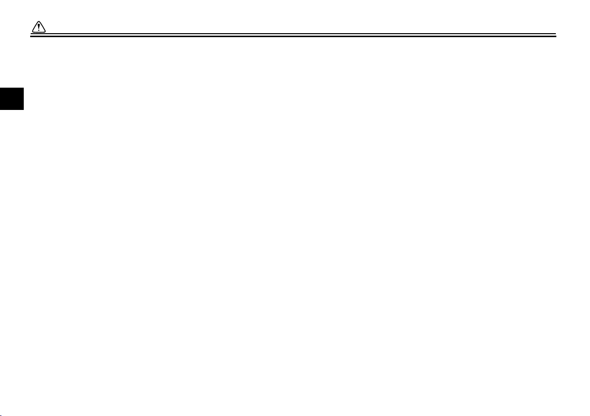
EAU10381
Location of important labels
Please read the following important labels carefully before operating this vehicle.
2
1
3
5
6
7
4

SAFETY INFORMATION
1-7
1
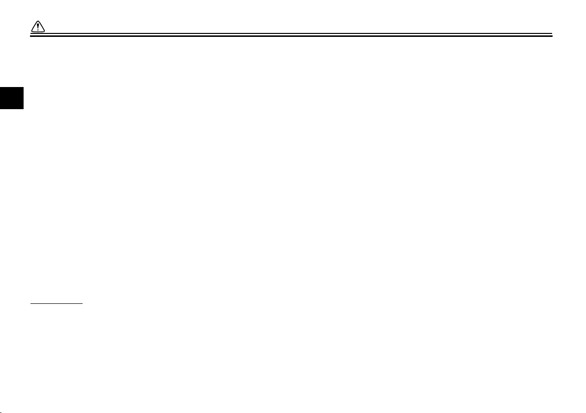
CAUTION
Cleaning
with
alkaline
or
acid
cleaner,
gasoline
or
solvent
will
damage
windshield.
Use
neutral
detergent.
3JJ
—
2835Y
—
A0
1
WARNING
BEFORE YOU OPERATE THIS VEHICLE, READ
THE OWNER’S MANUAL AND ALL LABELS.
ALWAYS WEAR AN APPROVED MOTORCYCLE
HELMET, eye protection, and protective clothing.
5GK-2118K-00
5RU-24877-A0
LOAD LIMIT
2 kg {4 lbs}
5RU-21668-00
WARNING
Improper loading can cause loss of control.
Read owner’s manual for proper loading.
3JJ
—
28446
—
A1
3LD-24877-A0
LOAD LIMIT
5 kg {11 lbs}
2
3
4
5
6

SAFETY INFORMATION
1-8
1
7
5RU
-
21686
-
00

2-1
1
2
3
4
5
6
7
8
9
DESCRIPTION
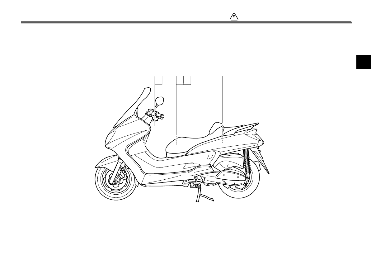
EAU10410
Left view
9
1
2 3
5
67
8
4
1011
1. Headlight (page 6-36)
2. Fuel tank cap (page 3-9)
3. Rear storage compartment (page 3-13)
4. V-belt case air filter element (page 6-20)
5. Owner’s tool kit (page 6-2)
6. Fuses (page 6-34)
7. Battery (page 6-33)
8. Air filter element (left) (page 6-20)
9. Engine oil filter element (page 6-14)
10. Centerstand (page 6-31)
11. Sidestand (page 3-15, 6-31)
DESCRIPTION
2-2
2
3
4
5
6
7
8
9
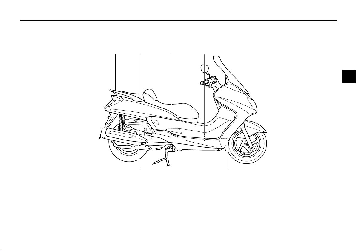
EAU10420
Right view
5
1
2
3
4
6
1. Grab bar (page 5-2)
2. Passenger seat (page 3-11)
3. Rider seat (page 3-11)
4. Coolant reservoir (page 6-18)
5. Radiator
6. Air filter element (right) (page 6-20)
DESCRIPTION
2-3
1
2
3
4
5
6
7
8
9
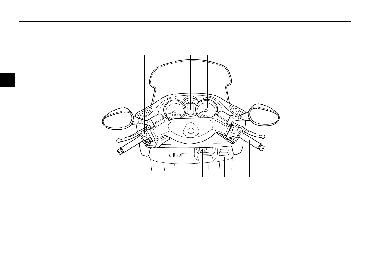
EAU10430
Controls and instruments
1345678
9101112
2
1. Rear brake lever (page 3-8)
2. Left handlebar switches (page 3-6)
3. Rear brake lock lever (page 3-8)
4. Speedometer (page 3-2)
5. Multi-function display (page 3-3)
6. Tachometer (page 3-3)
7. Right handlebar switches (page 3-6)
8. Front brake lever (page 3-7)
9. Throttle grip (page 6-23)
10. Front storage compartment B (page 3-13)
11. Main switch/steering lock (page 3-1)
12. Front storage compartment A (page 3-13)

3-1
2
3
4
5
6
7
8
9
INSTRUMENT AND CONTROL FUNCTIONS
EAU10460
Main switch/steering lock
The main switch/steering lock controls
the ignition and lighting systems, and is
used to lock the steering. The various
positions are described below.
EAU36070
ON
All electrical circuits are supplied with
power; the meter lighting, taillight, li-
cense plate light and position lights
come on, and the engine can be start-
ed. The key cannot be removed.
NOTE:
The headlights come on automatically
when the engine is started and stay on
until the key is turned to “OFF” or the
sidestand is moved down.
EAU10660
OFF
All electrical systems are off. The key
can be removed.
EAU10680
LOCK
The steering is locked, and all electrical
systems are off. The key can be re-
moved.
To lock the steering
1. Turn the handlebars all the way to
the left.
2. Push the key in from the “OFF” po-
sition, and then turn it to “LOCK”
while still pushing it.
3. Remove the key.
To unlock the steering
Push the key in, and then turn it to
“OFF” while still pushing it.
WARNING
EWA10060
Never turn the key to “OFF” or
“LOCK” while the vehicle is moving,
otherwise the electrical systems will
be switched off, which may result in
loss of control or an accident. Make
sure that the vehicle is stopped be-
fore turning the key to “OFF” or
“LOCK”.
INSTRUMENT AND CONTROL FUNCTIONS
3-2
1
2
3
4
5
6
7
8
9
EAU11003
Indicator and warning lights
EAU11030
Turn signal indicator lights “” and
“”
The corresponding indicator light flash-
es when the turn signal switch is
pushed to the left or right.
EAU11080
High beam indicator light “”
This indicator light comes on when the
high beam of the headlight is switched
on.
EAU11480
Engine trouble warning light “”
This warning light comes on when an
electrical circuit monitoring the engine
is defective. When this occurs, have a
Yamaha dealer check the self-diagno-
sis system.
The electrical circuit of the warning light
can be checked by turning the key to
“ON”. If the warning light does not come
on for a few seconds, then go off, have
a Yamaha dealer check the electrical
circuit.
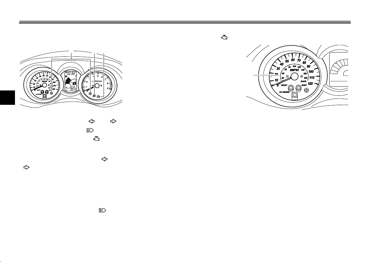
EAU11601
Speedometer
The speedometer shows the riding
speed.
When the key is turned to “ON”, the
speedometer needle will sweep once
across the speed range and then return
to zero in order to test the electrical cir-
cuit.
1. Turn signal indicator lights “” and “”
2. High beam indicator light “”
3. Engine trouble warning light “”
123
1. Speedometer
1

INSTRUMENT AND CONTROL FUNCTIONS
3-3
2
3
4
5
6
7
8
9
EAU11872
Tachometer
The electric tachometer allows the rider
to monitor the engine speed and keep it
within the ideal power range.
When the key is turned to “ON”, the ta-
chometer needle will sweep once
across the r/min range and then return
to zero r/min in order to test the electri-
cal circuit.
CAUTION:
ECA10031
Do not operate the engine in the ta-
chometer red zone.
Red zone: 8250 r/min and above
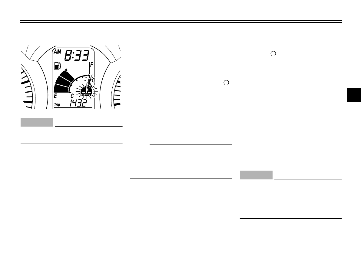
EAU36104
Multi-function display
WARNING
EWA12311
Be sure to stop the vehicle before
making any setting changes to the
multi-function display.
The multi-function display is equipped
with the following:
●
a fuel meter
●
a coolant temperature meter
●
an odometer (which shows the to-
tal distance traveled)
●
two tripmeters (which show the
distance traveled since they were
last set to zero)
●
a fuel reserve tripmeter (which
shows the distance traveled since
the bottom segment of the fuel
meter and fuel level warning indi-
1. Tachometer
2. Tachometer red zone
1
2
1. Clock/ambient temperature display
2. Coolant temperature meter
3. Fuel meter
4. Odometer/tripmeters
5. “SELECT” button
6. “RESET” button
1
2
3
4
5
6
1. V-belt replacement indicator “V-BELT”
2. Fuel level warning indicator “”
3. Coolant temperature warning indicator
“”
4. Oil change indicator “OIL”
12
3
4

INSTRUMENT AND CONTROL FUNCTIONS
3-4
1
2
3
4
5
6
7
8
9
cator started flashing)
●
a self-diagnosis device
●
a clock
●
an ambient temperature display
●
an oil change indicator
●
a V-belt replacement indicator
NOTE:
●
Be sure to turn the key to “ON” be-
fore using the “SELECT” and “RE-
SET” buttons.
●
When the key is turned to “ON”, all
of the display segments of the
multi-function display will appear
one after the other and then disap-
pear, in order to test the electrical
circuit.
Odometer and tripmeter modes
Pushing the “SELECT” button switches
the display between the odometer
mode “ODO” and the tripmeter modes
“TRIP” in the following order:
ODO
→
TRIP (top)
→
TRIP (bottom)
→
ODO
When approximately 2.8 L (0.74 US
gal) (0.62 Imp.gal) of fuel remains in the
fuel tank, the bottom segment of the
fuel meter and fuel level warning indica-
tor will start flashing, and the display will
automatically change to the fuel re-
serve tripmeter mode “TRIP F” and
start counting the distance traveled
from that point. In that case, pushing
the “SELECT” button switches the dis-
play between the various tripmeter and
odometer modes in the following order:
TRIP F
→
TRIP (top)
→
TRIP (bottom)
→
ODO
→
TRIP F
To reset a tripmeter, select it by push-
ing the “SELECT” button until “TRIP” or
“TRIP F” begins flashing (“TRIP” or
“TRIP F” will only flash for five sec-
onds). While “TRIP” or “TRIP F” is
flashing, push the “RESET” button for
at least one second. If you do not reset
the fuel reserve tripmeter manually, it
will reset itself automatically and the
display will return to the prior mode af-
ter refueling and traveling 5 km (3 mi).
NOTE:
The display cannot be changed back to
“TRIP F” after pushing the “RESET”
button.
Fuel meter
With the key in the “ON” position, the
fuel meter indicates the amount of fuel
in the fuel tank. The display segments
of the fuel meter disappear towards “E”
(Empty) as the fuel level decreases.
When the fuel level reaches the bottom
segment near “E”, the fuel level warn-
ing indicator and the bottom segment
will flash. Refuel as soon as possible.
Coolant temperature meter
With the key in the “ON” position, the
coolant temperature meter indicates
the temperature of the coolant. The
coolant temperature varies with chang-
es in the weather and engine load. If
the top segment and coolant tempera-
ture warning indicator flash, stop the
1. Fuel reserve tripmeter
1
INSTRUMENT AND CONTROL FUNCTIONS
3-5
2
3
4
5
6
7
8
9
vehicle and let the engine cool. (See
page 6-40.)
CAUTION:
ECA10020
Do not operate the engine if it is
overheated.
Oil change indicator “OIL”
This indicator flashes at the initial
1000 km (600 mi), then at 5000 km
(3000 mi) and every 5000 km (3000
mi) thereafter to indicate that the en-
gine oil should be changed.
After changing the engine oil, reset the
oil change indicator. (See page 6-14.)
If the engine oil is changed before the
oil change indicator comes on (i.e. be-
fore the periodic oil change interval has
been reached), the indicator must be
reset after the oil change for the next
periodic oil change to be indicated at
the correct time. (See page 6-14.)
The electrical circuit of the indicator can
be checked according to the following
procedure.
1. Set the engine stop switch to “”
and turn the key to “ON”.
2. Check that the indicator comes on
for a few seconds and then goes
off.
3. If the indicator does not come on,
have a Yamaha dealer check the
electrical circuit.
NOTE:
The oil change indicator may flash
when the engine is revved with the
scooter on the centerstand, but this
does not indicate a malfunction.
V-belt replacement indicator
“V-BELT”
This indicator flashes every 20000 km
(12500 mi) when the V-belt needs to be
replaced.
The electrical circuit of the indicator can
be checked according to the following
procedure.
1. Turn the key to “ON” and make
sure that the engine stop switch is
set to “”.
2. If the indicator does not come on,
have a Yamaha dealer check the
electrical circuit.
Self-diagnosis device
This model is equipped with a self-diag-
nosis device for various electrical cir-
cuits.
If any of those circuits are defective, the
multi-function display will indicate a
two-digit error code (e.g., 12, 13, 14).
If the multi-function display indicates
such an error code, note the code num-
ber, and then have a Yamaha dealer
check the vehicle.
CAUTION:
ECA11790
If the multi-function display indi-
cates an error code, the vehicle
should be checked as soon as pos-
sible in order to avoid engine dam-
age.
INSTRUMENT AND CONTROL FUNCTIONS
3-6
1
2
3
4
5
6
7
8
9
Clock mode
To set the clock:
1. Push the “SELECT” button and
“RESET” button together for at
least two seconds.
2. When the hour digits start flashing,
push the “RESET” button to set the
hours.
3. Push the “SELECT” button, and
the minute digits will start flashing.
4. Push the “RESET” button to set
the minutes.
5. Push the “SELECT” button and
then release it to start the clock.
Pushing the “SELECT” button for
at least two seconds switches the
clock display to the ambient tem-
perature display.
Ambient temperature display
This display shows the ambient tem-
perature from –10 °C (14 °F) to 50 °C
(122 °F) in 1 °C or 1 °F increments. The
temperature displayed may vary from
the ambient temperature. Pushing the
“SELECT” button for at least two sec-
onds switches the ambient temperature
display to the clock display.
NOTE:
●
If the ambient temperature falls be-
low –10 °C (14 °F), a lower tem-
perature than –10 °C (14 °F) will
not be displayed.
●
If the ambient temperature climbs
above 50 °C (122 °F), a higher
temperature than 50 °C (122 °F)
will not be displayed.
●
The accuracy of the temperature
reading may be affected when
riding slowly (approximately under
20 km/h (12.5 mi/h)) or when
stopped at traffic signals, railroad
crossings, etc.
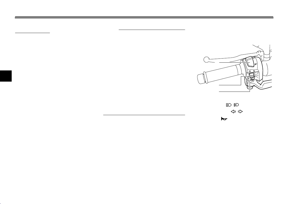
EAU12346
Handlebar switches
Left
1. Dimmer switch “ / ”
2. Turn signal switch “ / ”
3. Horn switch “”
1
2
3

INSTRUMENT AND CONTROL FUNCTIONS
3-7
2
3
4
5
6
7
8
9
Right
EAU12400
Dimmer switch “ / ”
Set this switch to “” for the high
beam and to “” for the low beam.
EAU12460
Turn signal switch “ / ”
To signal a right-hand turn, push this
switch to “”. To signal a left-hand
turn, push this switch to “”. When re-
leased, the switch returns to the center
position. To cancel the turn signal
lights, push the switch in after it has re-
turned to the center position.
EAU12500
Horn switch “”
Press this switch to sound the horn.
EAU12660
Engine stop switch “ / ”
Set this switch to “” before starting
the engine. Set this switch to “” to
stop the engine in case of an emergen-
cy, such as when the vehicle overturns
or when the throttle cable is stuck.
EAU12720
Start switch “”
With the sidestand up, push this switch
while applying the front or rear brake to
crank the engine with the starter.
CAUTION:
ECA10050
See page 5-1 for starting instruc-
tions prior to starting the engine.
EAU12900
Front brake lever
The front brake lever is located on the
right handlebar grip. To apply the front
brake, pull this lever toward the handle-
bar grip.
1. Engine stop switch “ / ”
2. Start switch “”
1
2
1. Front brake lever
1

INSTRUMENT AND CONTROL FUNCTIONS
3-8
1
2
3
4
5
6
7
8
9
EAU12950
Rear brake lever
The rear brake lever is located on the
left handlebar grip. To apply the rear
brake, pull this lever toward the handle-
bar grip.
EAU12962
Rear brake lock lever
This vehicle is equipped with a rear
brake lock lever to prevent the rear
wheel from moving while stopped at
traffic signals, railroad crossings, etc.
To lock the rear wheel
Push the rear brake lock lever to the left
until it snaps into place.
To unlock the rear wheel
Push the rear brake lock lever back to
the original position.
NOTE:
●
Be sure to check that the rear
wheel does not move when the
rear brake lock lever is applied.
●
To provide secure locking of the
rear wheel, apply the rear brake le-
ver first before moving the rear
brake lock lever to the left.
WARNING
EWA12361
Never move the rear brake lock lever
to the left while the vehicle is mov-
ing, otherwise loss of control or an
accident may result. Make sure that
the vehicle is stopped before mov-
ing the rear brake lock lever to the
left.
1. Rear brake lever
1
1. Rear brake lock lever
1

INSTRUMENT AND CONTROL FUNCTIONS
3-9
2
3
4
5
6
7
8
9
EAU13161
Fuel tank cap
To open the fuel tank cap
1. Open the lid by sliding the lever
forward, and then pull the lever up.
2. Insert the key into the lock and turn
it clockwise. The lock will be re-
leased and the fuel tank cap can
be removed.
To install the fuel tank cap
1. Align the match marks, insert the
fuel tank cap into the tank opening,
and then push down on the cap.
2. Turn the key counterclockwise to
the original position, and then re-
move it.
3. Close the lid.
WARNING
EWA11120
Be sure that the fuel tank cap is
properly installed and locked before
riding the scooter.
1. Lid
2. Opening lever
2
1
1. Fuel tank cap
1. Match marks
1
1

INSTRUMENT AND CONTROL FUNCTIONS
3-10
1
2
3
4
5
6
7
8
9
EAU13211
Fuel
Make sure that there is sufficient fuel in
the tank. Fill the fuel tank to the bottom
of the filler tube as shown.
WARNING
EWA10880
●
Do not overfill the fuel tank, oth-
erwise it may overflow when the
fuel warms up and expands.
●
Avoid spilling fuel on the hot en-
gine.
CAUTION:
ECA10070
Immediately wipe off spilled fuel
with a clean, dry, soft cloth, since
fuel may deteriorate painted surfac-
es or plastic parts.
EAU36080
CAUTION:
ECA11400
Use only unleaded gasoline. The use
of leaded gasoline will cause severe
damage to internal engine parts,
such as the valves and piston rings,
as well as to the exhaust system.
Your Yamaha engine has been de-
signed to use regular unleaded gaso-
line with a pump octane number
[(R+M)/2] of 86 or higher, or a research
octane number of 91 or higher. If
knocking (or pinging) occurs, use a
gasoline of a different brand or premi-
um unleaded fuel. Use of unleaded fuel
will extend spark plug life and reduce
maintenance costs.
Gasohol
There are two types of gasohol: gaso-
hol containing ethanol and that contain-
ing methanol. Gasohol containing
ethanol can be used if the ethanol con-
tent does not exceed 10%. Gasohol
containing methanol is not recom-
mended by Yamaha because it can
cause damage to the fuel system or ve-
hicle performance problems.
1. Fuel tank filler tube
2. Fuel level
2
1
Recommended fuel
UNLEADED GASOLINE ONLY
Fuel tank capacity:
14.0 L (3.70 US gal) (3.08 Imp.gal)
INSTRUMENT AND CONTROL FUNCTIONS
3-11
2
3
4
5
6
7
8
9
EAU13431
Catalytic converter
This model is equipped with a catalytic
converter in the exhaust system.
WARNING
EWA10860
The exhaust system is hot after op-
eration. Make sure that the exhaust
system has cooled down before do-
ing any maintenance work.
CAUTION:
ECA10700
The following precautions must be
observed to prevent a fire hazard or
other damages.
●
Use only unleaded gasoline.
The use of leaded gasoline will
cause unrepairable damage to
the catalytic converter.
●
Never park the vehicle near pos-
sible fire hazards such as grass
or other materials that easily
burn.
●
Do not allow the engine to idle
too long.
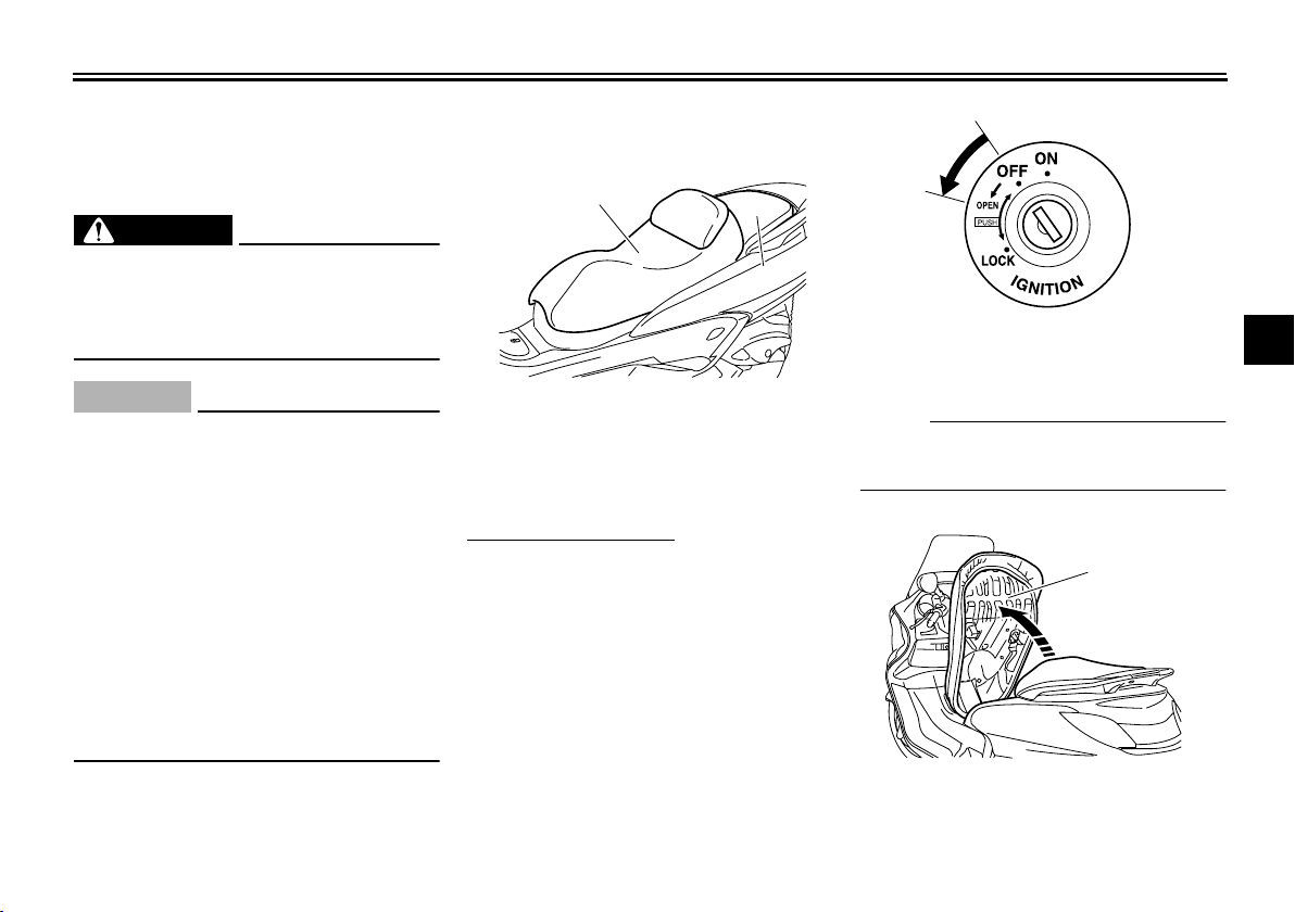
EAU34140
Seats
Rider seat
To open the rider seat
1. Place the scooter on the center-
stand.
2. Insert the key into the main switch,
and then turn it counterclockwise.
NOTE:
Do not push inward when turning the
key.
3. Fold the rider seat up.
1. Rider seat
2. Passenger seat
2
1
1. Open.
1. Rider seat
1
1
INSTRUMENT AND CONTROL FUNCTIONS
3-12
1
2
3
4
5
6
7
8
9
To close the rider seat
1. Fold the rider seat down, and then
push it down to lock it in place.
2. Remove the key from the main
switch if the scooter will be left un-
attended.
NOTE:
Make sure that the rider seat is properly
secured before riding.
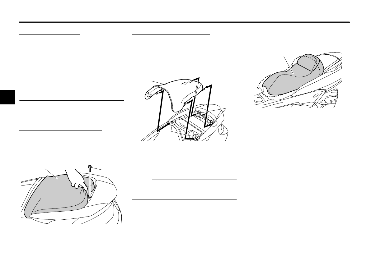
Passenger seat
To remove the passenger seat
1. Open the rider seat.
2. Remove the bolt, and then pull the
passenger seat forward.
To install the passenger seat
1. Insert the projections on the pas-
senger seat into the holders as
shown, place the passenger seat
in the original position, and then in-
stall the bolt.
2. Close the rider seat.
NOTE:
Make sure that the passenger seat is
properly secured before riding.
EAU34150
Adjusting the rider seat
The rider seat can be adjusted as fol-
lows to change the riding position.
1. Open the rider seat. (See
page 3-11.)
2. Remove the bolts.
1. Passenger seat
2. Bolt
2
1
1. Passenger seat
2. Seat holder
1
2
2
1. Rider seat
1
Loading...