


DX21
YAMAHA
AUTHORIZED
PRODUCT MANUAL
DIGITAL PROGRAMMABLE ALGORITHM SYNTHESIZER
YAMAHA
DIGITAL PROGRAMMABLE ALGORITHM SYNTHESIZER
OWNER’S MANUAL

CONGRATULATIONS!
Your Yamaha DX21 Digital Programmable Algorithm Synthsizer incorporates the
state-of-the-art in digital FM tone generation technology, providing extraordinarily vi-
brant, rich voices and outstanding playability. The DX21 actually has two FM tone
generators, permitting two voices to be combined and played simultaneously, or in a
split keyboard configuration. The DX21 has a 32-voice programmable RAM memory
from which any voice can be selected at the touch of a button, a built-in 128-voice preset
ROM memory from which voices can be called into the RAM memory as desired, 32
special “performance” memories which can be programmed with combinations of voices
and some function parameters, and a cassette interface that permits unlimited storage
of FM voices. Of course, the DX21 is fully programmable, allowing you to create your
own FM voices or sound effects. Broad MIDI compatibility is also provided so the DX21
can control or be controlled via other MIDI compatible music equipment. To ensure
that you gain maximum benefit from all the performance and flexibility provided by the
DX21, we urge you to read this owner’s manual thoroughly while actually trying out
all of the available functions.
PRECAUTIONS..
CHAPTER
AudioOutputs
1.
2. Optional Foot Controllers & Foot Switches
3.
Optional
4.
Headphones.............................................................
5.
MIDITerminals
6.
Cassette...................................................................
7.ACPower.................................................................
8. Music Rack Installation
CHAPTER II:PLAYING THE
1.
The 32 Voice
2.
The SINGLE
3.
The
4.
The
5.
The
CHAPTER III: THE FUNCTION MODE
1.
Accessing the
EnteringFunction
2.
The Performance Parameters
3.
4.
TuningFunctions
5.
MemoryManagement Functions
6.
MIDI
............................................................
I:
SETTlNG
BC1
DUAL
SPLIT
128 Voice ROM Memory
Functions
UP...........................................
..........................................................
Breath
RAM
Play
Play
Play
Controller...............................
.........................................................
............................................
DX21
.....................................
Memory...................................
Mode..........................................
Mode.............................................
Mode.............................................
.......................................
................................
FUNCTION
Data..........................................
....................................................
.........................................................
Mode..............................
...............................
...........................
..............
CONTENTS
2
CHAPTER IV: THE PERFORMANCE MEMORY..
1.
3
3
3
3
3
3
3
4
4
5
5
5
6
6
7
9
9
9
10
14
15
20
Performance
2.
Accessing
3.
Programming the Performance Memory
4.
ThePerformance
CHAPTER V: VOICE PROGRAMMING
1.
The
2.
The EDIT and
3.
The
4.
STORING
5.
Two Approaches to Creating
Your
GENERALSPECIFICATIONS
MIDI
DATA
1.
Transmission Parameters.......................................
2.
Transmission Data
3.
Reception
4.
Reception
5.
System
DATA
CHART
...............
Memory
thePerformanceMemory......................
ofFMSynthesis...................................
Basics
COMPARE
Parameters.............................................
Voice
VoiceData..............................................
Voices.....................................................
Own
FORMAT
Parameters.............................................
Data.......................................................
Exclusive
..................................................................
Organization........................
...............
Name.........................................
..............................
modes.............................
......................................
.......................................................
................................................
Data
............................................
22
22
22
22
22
23
23
28
28
36
36
37
38
38
38
41
42
45
49
1

1. Location
2. Cleaning
3. Service and
Modifications
4. Relocation
5. Handing
PRECAUTIONS
Choose the installation location for the DX21 with caution. Avoid locations exposed
to direct sunlight or other sources of heat. Also avoid locations subject to vibration,
excessive dust, cold or moisture.
Do not attempt to clean the exterior with chemical solvents, as this may damage
the finish. Clean with a soft, dry cloth.
Do not open the cabinet or attempt to make your own repairs or modifications to
any part of the instrument. Such actions may not only result in electrical shock or
damage, but will also void the product warranty. Refer all servicing to a qualified
Yamaha service center.
When moving the instrument be sure to unplug the AC mains cord as well as all
other connecting cables.
Avoid applying excessive force to switches and slide controls, dropping or rough
handling. The DX21 is ruggedly constructed using reliable solid-state circuitry,
nonetheless it is a fine instrument that should be treated with care.
6. Electrical Storms
(Lightning)
7. Electromagnetic
Fields
Digital circuitry such as that used in the DX21 is sensitive to voltage spikes and
surges. Because of this, the DX21 should be turned off and unplugged from the
AC power outlet in the event of an electrical storm.
Digital circuitry is also sensitive to electromagnetic fields such as those produced
by television sets, radio receivers, transmitters, transceivers, etc. The DX21 should
kept at least several feet from such sources in order to prevent possible random
malfunctions.
2

1. Audio Outputs
2. Optional Foot
Controllers & Foot
Switches
3. Optional BC1
CHAPTER I: SETTING UP
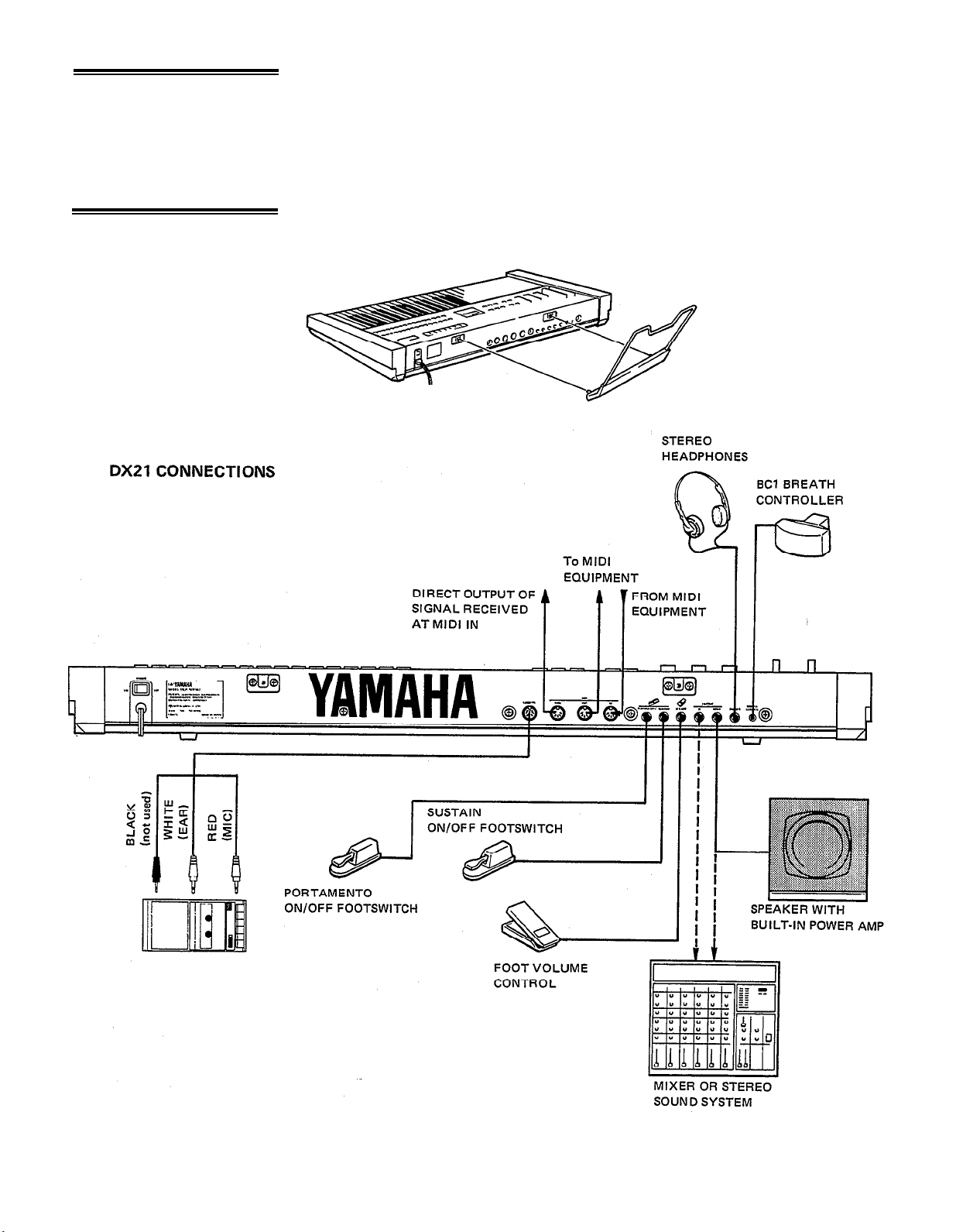
The DX21 has two audio outputs, one for each tone generator channel. These
are labelled MIX/A and B. When a plug is plugged into the MIX/A output only,
the sound from both the A and B tone generator channels will be mixed and delivered
via the MIX/A output. When plugs are inserted into both MIX/A and B jacks,
however, the channel A signal will be delivered via the MIX/A output and the
channel B signal will be delivered via the B output. This permits sending a stereo
signal to a stereo sound system giving you the full impact of the DX21’s dual and
split play mode capability.
The remaining three phone jacks are for optional foot controllers and footswitches.
The VOLUME jack accepts a Yamaha FC-7 or equivalent foot controller for volume
or “swell” control. The SUSTAIN jack accepts a Yamaha FC-4 or FC-5 footswitch
or equivalent for sustain control–press for sustain, release to damp. And the
PORTAMENTO jack also accepts a Yamaha FC-4 or FC-5 footswitch or equivalent
permitting ON/OFF switching of the programmed portamento effect.
Yamaha’s unique BC1 breath controller is plugged into the mini-jack on the rear
panel.
Breath Controller
4. Headphones
5. MIDI Terminals
6. Cassette
The PHONES jack accepts any standard pair of stereo headphones. When a plug
is plugged into the B output only, the channel A and channel B signals are delivered
to the headphones in stereo. When the B output is not connected, both A and B
signals are mixed and output from PHONES jack. Headphone volume is controlled
via the VOLUME control on the top panel.
These terminals are used when connecting the DX21 to other MIDI (Musical Instrument Digital Interface) compatible equipment such as digital sequence re-
corders, modular FM voice generators, drum machines, etc. The MIDI OUT terminal
transmits MIDI data from the DX21 to other MIDI equipment. The MIDI OUT
terminal will normally be connected to the MIDI IN terminal of the receiving
equipment. The MIDI IN terminal accepts MIDI data from external MIDI equipment
such as a digital sequence recorder, music computer or modular FM voice generator.
THe DX21’s MIDI IN terminal will normally be connected to the MIDI OUT terminal
of the transmitting equipment. The MIDI THRU terminal re-transmits the data re-
ceived at the MIDI IN terminal. Thus, data received via the DX21 MIDI IN terminal
can be simultaneously sent to other MIDI equipment.
The DIN connector end of the supplied cassette cable is plugged into the DX21
CASSETTE connector. The three plugs on the other end of the cable should be
connected to a cassette data recorder (the kind normally used with personal
computers, etc.) as follows:
RED
WHITE
BLACK
cassette deck microphone input.
cassette deck earphone output.
cassette deck remote input (The DX21 does not output cassette
remote control signals, so this jack may be left unconnected).
3
7. AC Power
8. Music Rack
lnstallation
Plug the DX21 AC power cord into an AC wall socket. Be sure that your local line
voltage matches that specified on the DX21 rear panel. The POWER switch is located
next to the AC cord on the rear panel. NOTE: When setting up your system, be
sure to turn the DX21 and any effects units used on BEFORE turning the main
amplifier system on. This will prevent the initial power-on shock surge from possible
damaging your amplifier and speaker system.
The music rack supplied with the DX21 fits into the two sockets on the rear panel
(see diagram).
4
CHAPTER II: PLAYING THE DX21
1. The 32 Voice RAM
Memory
The DX21 has 32 RAM (Random Access Memory) locations which contain voices
which may be immediately selected by pressing the appropriate memory button
while the DX21 is in one of the three normal play modes described below. The two
rows of 16 buttons- row A and row B-are the voice memory selectors. The row
A and B selectors correspond to DX21 tone generator channels A and B.
These same buttons actually serve a number of functions. In the FUNCTION and
EDIT modes--which are covered in later sections of this manual--they serve to select
the function or edit parameter to be programmed.
Since RAM memory can be written to as well as read from, it is possible to load
new voice data into the 32 available RAM memory locations. This can be done
by loading new voices from the DX21’s internal 128-voice ROM (Read Only
Memory) into the RAM memory (see “5. The 128 Voice ROM Memory”, below),
or by loading a new set of 32 voices from data stored on an external cassette tape
(see CHAPTER III: THE FUNCTION MODE, Memory Management Functions).
2. The SINGLE Play
Mode
If you’re just starting out, you’ll want to try out the voices that are pre-programmed
into the RAM memory. You can do this in any of the three play modes discussed
below. Make sure your DX21 is properly connected to a sound system--or you
could simply plug a pair of headphones into the PHONES jack (see CHAPTER
I: SETTING UP), set the VOLUME control to about its center position, and set
the A/B BALANCE control to its center position (you’ll feel a “click” stop at dead
center). Now you can start experimenting with the DX21 voices in the SINGLE
play mode.
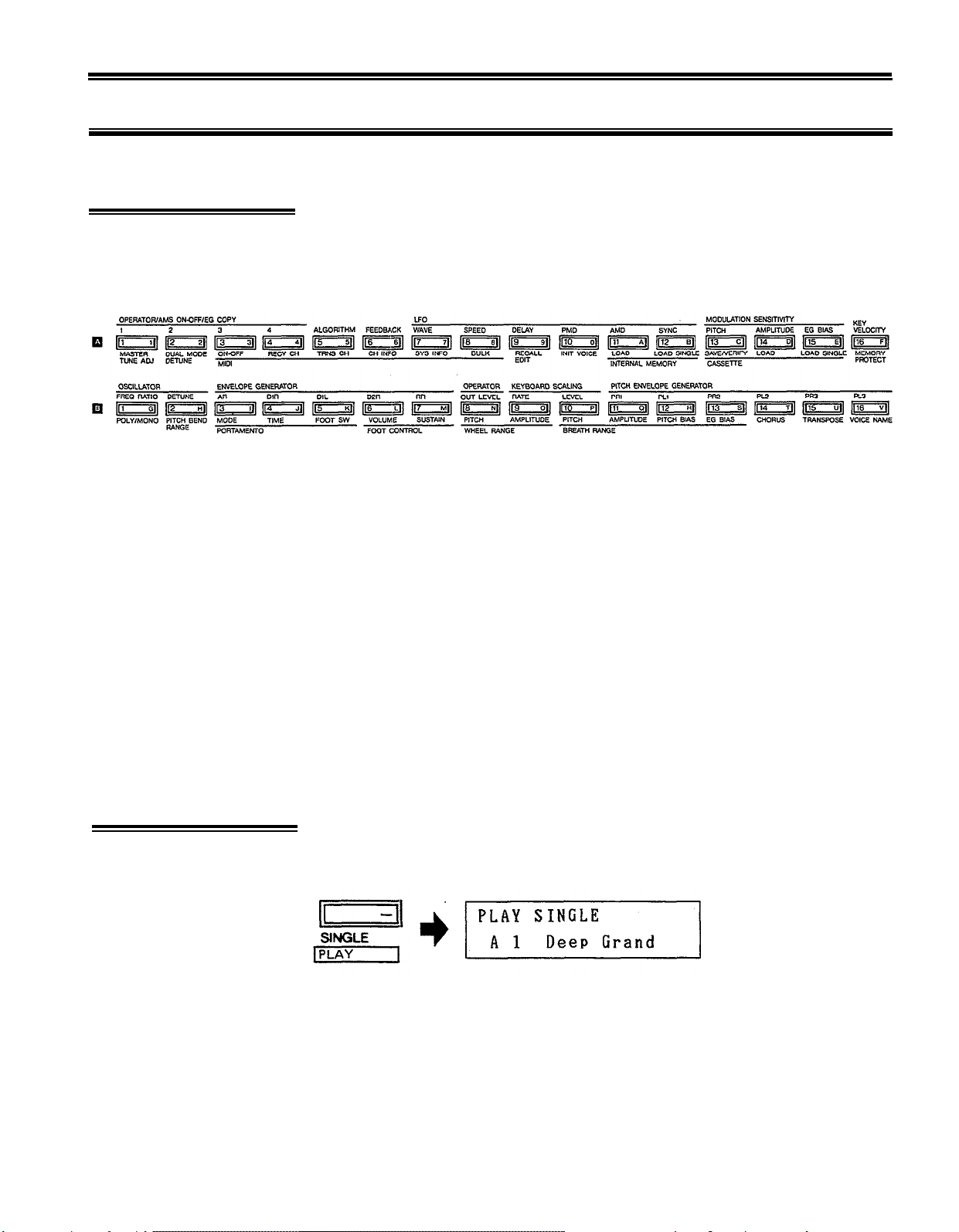
Enter the SINGLE play mode by pressing the PLAY SINGLE button to the left of
the LCD (Liquid Crystal Display) panel. When you do this the LCD will look
something like this.
The top line of the LCD reads “PLAY SINGLE”, indicating that you are in the SINGLE
play mode, and the bottom display line will indicate the selected memory location
number (A1 through A16, or B1 through B16) followed by the name of the selected
voice.
In this mode you can play any of the voices currently in the DX21’s RAM memory
individually.
5
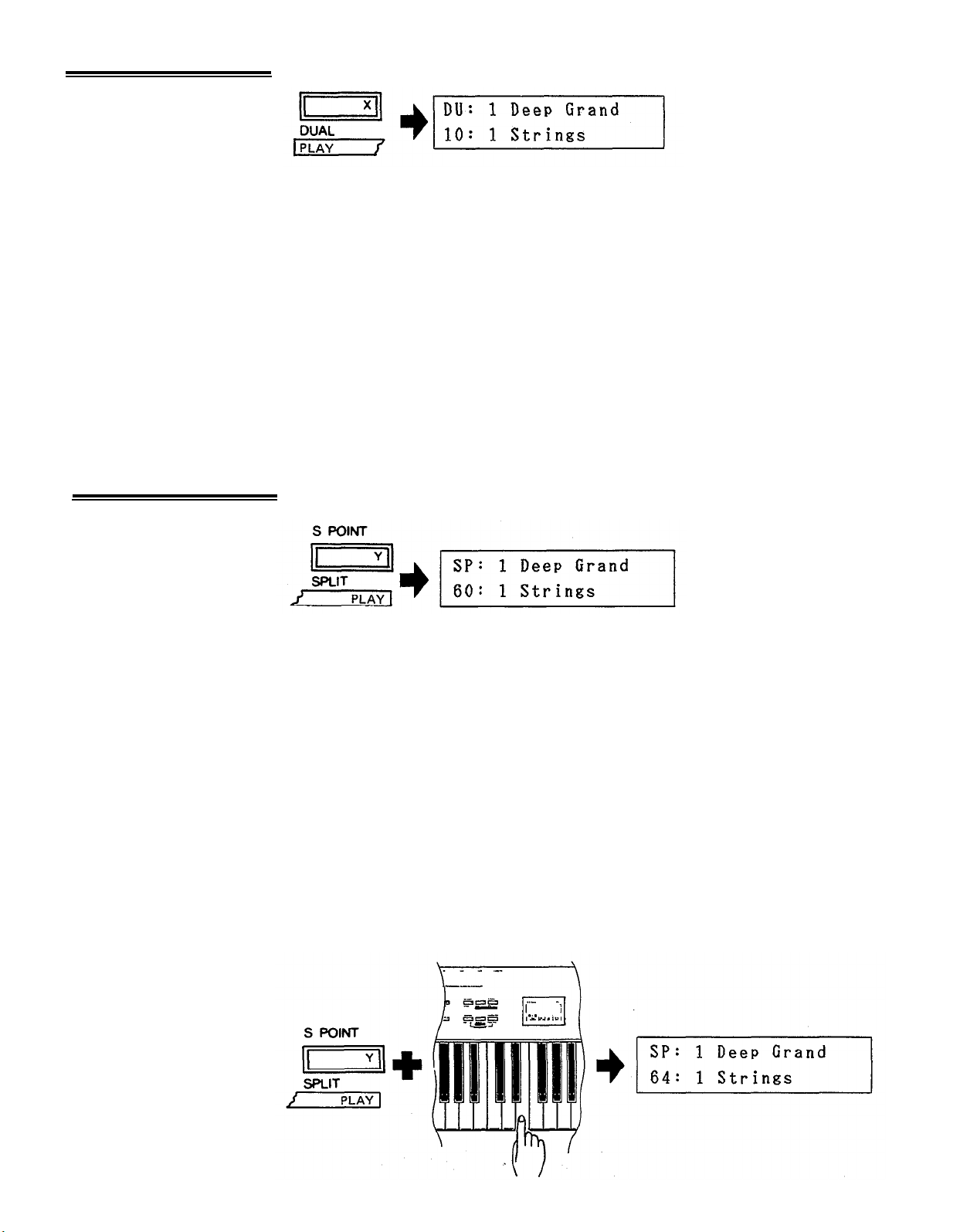
3. The DUAL Play
Mode
4. The SPLIT Play
Mode
Enter the DUAL mode by pressing the PLAY DUAL button.
“DU” in the upper left display corner indicates that the DUAL mode has been selected. The upper display line now shows the number and name of any voice selected
from the “A” row of memory selectors, while the lower display line shows the number
and name of any voice selected from the “B” row of voice selectors. The number
in the lower left display corner indicates the value of the DUAL MODE DETUNE
(see CHAPTER III: THE FUNCTION MODE).
In this mode any of the 16 voices from tone generator “A” can be selected and
combined with any voice from tone generator “B”. As you try out various combinations of voices you’ll notice that some voices are louder than others, resulting
in one voice overpowering the other when two are combined. This can be adjusted
by using the A/B BALANCE control. Moving this control more towards the “A”
end of the scale increases the volume of the “A” voice while decreasing the volume
of the “B” voice. Moved in the opposite direction—towards “B”—it has the opposite
effect. Use this control to achieve the best balance between the two selected voices
in the DUAL play mode.
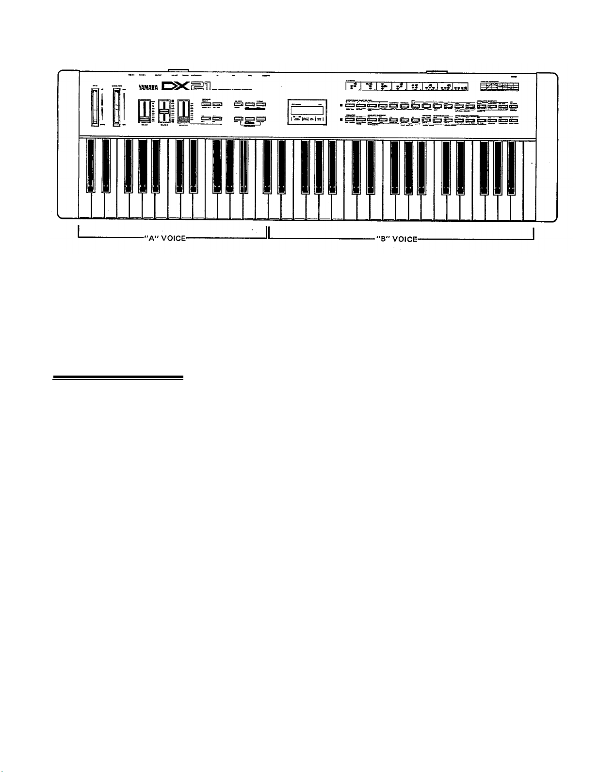
Enter the SPLIT mode by pressing the PLAY SPLIT button.
“SP” in the upper left display corner indicates that the SPLIT mode has been selected.
As in the DUAL mode the number and name of one voice selected from the “A”
row will be shown on the upper display line, and the number and name of a voice
selected from the “B” row will be shown on the lower display line. Unlike the DUAL
mode, however, the two selected voices do not sound together. The “A” voice
will be assigned to all keys to the left of and including the programmed “split” key,
while the “B” voice will be assigned to all keys to the right of the split key. This
type of arrangement lets you assign a bass voice, for example, to the left side of
the keyboard and a piano voice to the right side of the keyboard so you can play
bass and piano lines simultaneously.
The next step is to decide on and program the desired split point. Note that at the
extreme left of the lower display line there is a number followed by a colon. This
is the number of the selected split point. To program the split point, simply press
the S POINT button (notice that this is the same as the PLAY SPLIT button you
used to enter the SPLIT mode) and while holding it down press the key on the
DX21 keyboard at which you want the split point to be programmed (C3=60).
6
SPLIT POINT set at 60
The split point number on the LCD will change to the number of the pressed key,
the “A” voice will be playable on all keys to its left (Including the split key), and
the “B” voice will be playable on all keys to the right of the split key. This process
can be repeated as many times as necessary, but you must press and hold the S
POINT key again every time you re-program the split point.
5. The 128 Voice ROM
Memory
As in the DUAL mode, the A/B BALANCE control can be used to balance the volume
levels of the “A” and “B” voices.
The DX21 comes with 128 different pre-programmed voices in an internal ROM
(Read Only Memory). These voices can be loaded in groups of 8, or singly, into
the DX21’s selectable 32-voice RAM memory. The ROM voices are organized into
16 different categories, each containing 8 voices (see next page).
To load these voices into the DX21's RAM voice memory for selection and use,
see A11: LOAD INTERNAL MEMORY and A12: LOAD SINGLE INTERNAL ME-
MORY in the following chapter.
7
THE 128 VOICES PROVIDED IN THE INTERNAL ROM
GROUP 1 : PIANO
DeepGrand
1
Uprt Piano 2
2
3
Honkey Tonk
Ivory Ebony
4
5
Phase Grand
Elec Grand
6
Piano bells
7
8
Acous Elec
GROUP 2 : ELECTRIC
1
Old Electra
2
New Electra
High Tines
3
Hard Tines
4
Perco Piano
5
WoodPiano
6
Vibrabelle
7
8
GROUP 3 : ORGAN
1
2
3
4
5
6
7
8
GROUP 4 :
1
2
3
4
5
6
7
8
brass
Piano
Click
Organ
Jazz Organ
Ham < n > Eggs
Drawbars
Club Organ
<6 Tease>
Gentle Pipe
8 Full Ranks
STRINGS
Strings
Silk Cello
Orchestra
Solo Violin
Box Cello
Rich string
5th String
Pizzicato
PIANO GROUP 6 : PLUCKED
GROUP 5 : BRASS GROUP 9 : PERCUSSION 2
Electro
1
Horns
Brite Brass
3
Flugel horn
Trombone
4
Hard Brass
5
Power Brass
6
BC1 Horns
7
BC1 Trumpet
8
1
Pluk guitar
2
Brt Guitar
3 Soft Harp
4 Sitar
5 Jazz Guit
Old Banjo
6
7
Kotokoto
8 Folk Guit
GROUP 7 : COMPING
Easy Synth
1
Easy Clav
2
3
>> WOW <<
4
Metal Keys
5
Cheeky
6
Rubber
Pick Pluck
7
S/H Synth
8
GROUP 8 : PERCUSSION 1
1
Glocken
2
Hamarimba
Steel Drums
3
4 Tube Bells
5 Temple gong
6 Mamarimbs
7
Good Vibes
8
Bells Bells
Band
1
2
3
4
5 Synballs
6
Clock werks
7
8
GROUP 10 : LEAD
1
2
3 Feed Lead
4 Mono Lead
5
6 Lyrisyn
7 Schmooh
8 Huff Talk 8 Birds
GROUP 11 : OTHER
1
2
3
4
5
6
7
8 Circus time
GROUP 12 : WIND REED
1
2
Bassoon
3
Pan Floot
4
5
6
<BC1>Sax
7
8
Tom
Timpani
Breakin
Xylo snare
Hand Drum 6 Elec Bass
Heifer Bell
SYNTH
Heavy synth
Harmo solo
Hollow lead
KEYBOARD
Harpsi low
Harpsi Hi
Fuzz Clav
Clear Clav
Mute Clav
Squeeze box
Celeste
Claranette
Lead Reed
Mono Sax
Flute wood
BC1 Hrmnca
GROUP 13 : BASS
Solid
1
2
3
4
5
7
8 Fretless
GROUP 14 : SOUND EFFECT 1
1 Racing Car
2
3
4
5
6
7
GROUP 15 : SOUND
1
2
3
4
5
6
7
8
GROUP 16: SOUND EFFECT 3
1 Wind bells
2
3
4
5
6
7
8
Bass
Pluck Bass
Synthe Bass
Mono Bass
Flap Bass
Uprt Bass
Helicopter
Alarm Call
Ghosties
Dopplar FX
Storm Wind
Space Talk
EFFECT
Diesel
Hole in 1
<<Smash>>
FM SQUARE
FM PULSE
FM SAW TOOTH
LFONOISE
PINK NOISE
Synvox
Punk funk
Whistling
Voices
Zing Plop
Valve Plop
Mars to ??
2
8
CHAPTER III: THE FUNCTION MODE
The FUNCTION mode permits access to four groups of functions:tuning functions, MIDI functions, memory
management functions, and performance functions. In this chapter we’ll describe each of these functions; what
they do and how they are programmed.
The FUNCTION mode is accessed by pressing the FUNCTION button to the left
1. Accessing the
FUNCTION Mode
of the LCD display. Individual parameters to be programmed are then called by
pressing the appropriate voice selector button. Note that when the FUNCTION
mode is active pressing a voice selector button calls the corresponding FUNCTION
parameter—these are the functions printed in brown below each voice selector.
Note that there are two exceptions: the PB (Pitch Bend) MODE SET and KEY SHIFT
KEY SET buttons are NOT included among the voice selectors. These function
selectors are located immediately above the DATA ENTRY -1 and +1 switches.
When the FUNCTION mode is called, the LCD should look something like this.
The top line of the display will. read “FUNCTION CONTROL”, indicating that the
FUNCTION mode is active, and the lower display line will show the name of the
selected function and its current data. In the example above, the MASTER TUNE
function is called (press the Al button) and the data is currently set at 0.
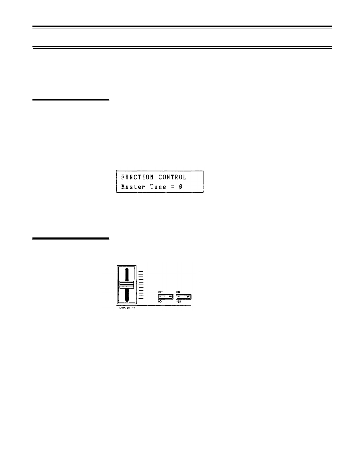
2. Entering Function
Data
Once the desired function has been selected, its value can be altered using either
the linear DATA ENTRY control located to the left of the panel, or the adjacent
-1 /NO/OFF and +1 /YES/ON switches.
Moving the DATA ENTRY control away from you increases the value of the selected
parameter, and moving the control towards you decreases the data value. Pressing
the -1 switch decreases the value of the selected parameter by one (decrements),
and pressing the +1 switch increases the value by one (increments). While the
DATA ENTRY control is valuable for quickly approaching the desired value with
parameters that have a large data range, the +1 and -1 switches permit precise
step-wise location of a specific value. The switches are also easier to use with
parameters that only have two values–e.g. ON (1) or OFF (0). In some cases you
will be required to answer YES or NO to prompts which will appear on the LCD
display. The -1 /NO/OFF and +1 /YES/ON switches are used for this.
9

3. The Performance
Parameters
“Performance parameters” are programmable parameters which pertain mainly to
real-time performance effects such as how the pitch bend and modulation wheels
affect the sound. All performance parameters can be memorized for each voice.
If you wish that the edited data will remain in the memory, you have to store it
using STORE function (see CHAPTER V: VOICE PROGRAMMING, “4. Storing
Voice Data”).
B1: POLY/MONO
This function selects either the POLY or MONO note output mode.
There are two possible settings: POLY and MONO. In the POLY mode the note
output configuration depends on the currently selected play mode. When the play
mode is set to SINGLE up to 8 notes can be played simultaneously. When set to
SPLIT up to 4 notes may be simultaneously played on each side of the split point
(4 + 4). When set to DUAL up to 4 notes may be played simultaneously. In the
MONO mode, which can only be selected when the DX21 is in the SINGLE play
mode, the DX21 acts as a last-note-priority monophonic keyboard. In the SPLIT
mode it is possible to select one POLY voice and one MONO voice. In this case
up to seven notes can be played simultaneously on the POLY voice and one on
the MONO voice.
Once the POLY/MONO function is selected, subsequent presses on the B1 button
alternate between the POLY and MONO modes. The DATA ENTRY switches can
also be used: the -1 switch selects POLY and the +1 switch selects MONO.
B2: PITCH BEND RANGE
This function sets the pitch range of the pitch bend wheel located to the left of
the DX21 panel. The pitch bend wheel automatically centers at normal pitch. It then
may be moved upward (away from the player to raise the pitch, or moved downward
(toward the player) to lower the pitch by the specified amount.
The data range is from 0 to 12. At 0 the pitch bend wheel is off. Each increment
between 1 and 12 represents a semitone. Thus if this function is set to 12, maximum
travel of the pitch bend wheel produces a one-octave pitch variation, both above
and below center position–i.e. plus or minus one octave.
The DATA ENTRY control and -1/+1 switches can be used to enter data. Once
the PITCH BEND RANGE function is called, subsequent presses on the B2 button
increment the data value.
PB MODE: MODE SET
This function selector, located immediately above the DATA ENTRY -1 button,
offers a choice of three pitch bend wheel modes: Low, High and K-on. In the Low
mode, the pitch bend wheel affects only the lowest note played on the keyboard.
In other words, if a chord is played, the pitch bend wheel affects only the pitch
of the lowest note in the chord—this makes it possible to produce some interesting
effects. The High mode is just the opposite—only the highest note played will be
affected by the pitch bend wheel. In the K-on (Key on) mode, all notes played
are affected simultaneously by the pitch bend wheel, while notes sustained using
the sustain footswitch will not be affected.
The DATA ENTRY control and -1/+1 switches can be used to select the desired
mode.
B3: PORTAMENTO MODE
Two different portamento modes are available: Full Time Portamento and Fingered
Portamento. When the POLY/MONO function is set to POLY (button B1), only
the Full Time Portamento mode is accessible. In the MONO mode, you have a choice
between the Full Time and Fingered portamento modes.
(1)“Full Time Porta” (MONO and POLY modes): Aconventional portamento effect
in which portamento occurs whenever a new note is played.
10

(2)“Fingered Porta” (MONO mode only): Portamento only occurs if the previously
played note is held while the next note is played. This mode is useful in recreating the effect of guitar string bending techniques, wood bass slide effects,
etc. If you lift your hand off the DX21 keyboard between notes, there will be
no portamento effect.
Once the PORTAMENTO MODE function is called, subsequent presses on the
B3 button alternate between the two available portamento modes only if the MONO
note output mode is selected. The DATA ENTRY switches can also be used to
select the desired portamento mode.
B4: PORTAMENTO TIME
This function sets the speed of the portamento effect.
The data range is from 0 to 99. At 0 portamento is off. A setting of 99 produces
the longest portamento effect.
Data can be entered using the DATA ENTRY control and -1/+1 switches. Once
the PORTAMENTO TIME function has been called, subsequent presses on the
B4 button increment the data value.
B5: PORTAMENTO FOOT SWITCH
This function turns the rear-panel PORTAMENTO footswitch jack ON or OFF.
When OFF the PORTAMENTO footswitch will NOT function. When ON the
PORTAMENTO footswitch connected to the PORTAMENTO jack can be used to
turn the portamento effect ON or OFF. (accepts Yamaha FC-4 or FC-5 foot
switches)
Once the PORTAMENTO FOOT SW function has been called, subsequent presses
on the B5 button alternate between the ON and OFF settings. The DATA ENTRY
switches can also be used to turn this function ON and OFF.
B6: FOOT CONTROL VOLUME
This function sets the control range of a foot volume controller (Yamaha FC-7,
optional) connected to the rear-panel VOLUME jack.
The data range is from 0 to 99. At 0 the foot controller is OFF and will have no
effect on the sound. At 99 the foot controller can be used to adjust output volume
over the full range from maximum volume to zero volume. Intermediate settings
permit corresponding degrees of “expression” or “swell” control.
The DATA ENTRY control and -1/+1 switches can be used to enter the data for
this function. Once the FOOT CONTROL VOLUME function is called, subsequent
presses on the B6 button increment the data value.
B7: FOOT CONTROL SUSTAIN
This function turns the sustain footswitch (Yamaha FC-4 or FC-5, optional)
connected to the rear-panel SUSTAIN jack ON or OFF. When ON the sustain pedal
can be used to control the sustain effect. When OFF the sustain pedal will not
function.
Once this function is called subsequent presses on the B7 button alternate between
the ON and OFF states. The DATA ENTRY switches can also be used to select the
desired mode.
B8: WHEEL RANGE (MODULATION WHEEL), PITCH
As you move the DX21 modulation wheel away from you an increasing amount
of LFO (Low Frequency Oscillator) modulation is applied to the selected voice.
LFO modulation can be made to modulate the pitch of the voice producing a range
of vibrato type effects. This function is used to set the maximum depth of pitch
modulation which can be applied using the modulation wheel. The actual effect
11

produced depends on the settings of the LFO parameters—these will be discussed
in CHAPTER V: VOICE PROGRAMMING. Note, however, that the appropriate
voice PITCH MODULATION SENSITIVITY parameter must be set to a value higher
than 0 for pitch modulation to be effective. The voice PITCH MODULATION
SENSITIVITY parameter will also be discussed in CHAPTER V. The data range is
from 0 to 99. At 0 pitch modulation is OFF, and rotating the modulation wheel
will cause no pitch modulation to be applied to the voice. A setting of 99 produces
the greatest possible pitch modulation depth.
Data is entered using the DATA ENTRY controls or switches. Once this function
is called, subsequent presses on the B8 button increment the data value.
B9: WHEEL RANGE (MODULATION WHEEL), AMPLITUDE
As you move the DX21 modulation wheel away from you an increasing amount
of LFO modulation is applied to the selected voice. LFO modulation can be made
to modulate the amplitude (level) of specified voice elements (operators), producing
a range of tremolo or timbre modulation (wow-wow) type effects. This function
is used to set the maximum depth of amplitude modulation which can be applied
using the modulation wheel. The actual effect produced depends on the settings
of the LFO parameters—these will be discussed in CHAPTER V: VOICE PRO-
GRAMMING. Note, however, that the appropriate voice AMPLITUDE MODU-
LATION SENSITIVITY parameter must be set to a value higher than 0 for amplitude
modulation to be effective. The voice AMPLITUDE MODULATION SENSITIVITY
parameter will also be discussed in CHAPTER V.
The data range is from 0 to 99. At 0 amplitude modulation is OFF, and rotating
the modulation wheel will cause no amplitude modulation to be applied to the voice.
A setting of 99 produces the greatest possible amplitude modulation depth.
Data is entered using the DATA ENTRY controls or switches. Once this function
is called, subsequent presses on the B9 button increment the data value.
The Yamaha Breath Controller
The optional Yamaha BC1 Breath Controller is a unique way of adding expression
to the sound as you play the DX21 keyboard. The BC1 is held in the mouth just
like the mouthpiece of a wind instrument. Blowing harder or softer into the BC1
mouthpiece then produces a corresponding effect. The Breath Controller can be
used to apply varying amounts of pitch or amplitude LFO modulation, just like the
modulation wheel. In addition it can be set up to directly affect pitch, amplitude
or timbre in response to breath pressure. Set to directly affect amplitude (EG BIAS),
for example, the Breath Controller can be used to apply realistic tonguing effects
to brass and other wind instrument sounds.
The four BREATH parameters listed below determine just how the Breath Controller
will affect the DX21 sound. These parameters may be set individually, or combined
for more complex effects.
B10: BREATH RANGE, PITCH
This function is used to set the maximum depth of LFO pitch modulation which
can be applied using the Breath Controller. The actual effect produced depends
on the settings of the LFO parameters—these will be discussed in CHAPTER V:
VOICE PROGRAMMING. Note, however, that the appropriate voice PITCH
MODULATION SENSITIVITY parameter must be set to a value higher than 0 for
pitch modulation to be effective. The voice PITCH MODULATION SENSITIVITY
parameter will be discussed in CHAPTER V: VOICE PROGRAMMING.
The data range is from 0 to 99. At 0 pitch modulation is OFF, and applying breath
pressure to the Breath Controller will cause no pitch modulation to be applied to
the voice. A setting of 99 produces the greatest possible pitch modulation depth.
12

Data is entered using the DATA ENTRY controls and -1/+1 switches. Once this
function is called, subsequent presses on the B10 button increment the data value.
B11: BREATH RANGE, AMPLITUDE
This function is used to set the maximum depth of LFO amplitude modulation which
can be applied using the Breath Controller. The actual effect produced depends
on the settings of the LFO parameters—these will be discussed in CHAPTER V:
VOICE PROGRAMMING.Note, however, that the appropriate voice AMPLITUDE
MODULATION SENSITIVITY parameter must be set to a value higher than 0 for
amplitude modulation to be effective. The voice AMPLITUDE MODULATION
SENSITIVITY parameter will be discussed in CHAPTER V: VOICE PROGRAM-
MING.
The data range is from 0 to 99. At 0 amplitude modulation is OFF, and applying
breath pressure to the Breath Controller will cause no amplitude modulation to
be applied to the voice. A setting of 99 produces the greatest possible amplitude
modulation depth.
Data is entered using the DATA ENTRY controls or switches. Once this function
is called, subsequent presses on the B11 button increment the data value.
B12: BREATH RANGE, PITCH BIAS
This function permits breath pressure applied to the BC1 Breath Controller to directly
control the pitch of the voice. In other words the LFO has no effect—only your
breath pressure directly affects the pitch of the voice.
The data range is from 0 to 99. At 50 pitch bias is OFF. A setting of 99 permits
the greatest pitch increase to be produced through the Breath Controller, while a
setting of 0 permits the greatest pitch decrease.
Data is entered using the DATA ENTRY controls and -1/+1 switches. Once this
function is called, subsequent presses on the B12 button increment the data value.
B13: BREATH RANGE, EG BIAS
This function permits breath pressure applied to the BC1 Breath Controller to directly
control the amplitude or timbre of the voice, according to settings of the corresponding voice parameters which will be covered in CHAPTER V. The LFO has
no effect—only your breath pressure directly affects the amplitude or timbre of the
voice.
The data range is from 0 to 99. At 0 EG bias is OFF. A setting of 99 permits the
greatest amplitude or timbre variation to be produced through the Breath Controller.
Data is entered using the DATA ENTRY controls and -1/+1 switches. Once this
function is called, subsequent presses on the B13 button increment the data value.
B14: CHORUS
The DX21 has a built-in chorus effect which can be used to add a pleasant stereo
chorus effect to any voice. Chorus is only effective, however, when both the DX21’s
A and B audio outputs are connected to a sound system in a stereo configuration.
The full impact of the chorus effect will not be heard if the A/MIX output only is
used, or if the A and B outputs are externally mixed to a mono signal.
This function turns the chorus effect ON or OFF. Once the CHORUS function is
called, subsequent presses on the B14 button alternate between the ON and OFF
states. The DATA ENTRY buttons can also be used to select the desired mode.
13

B15: TRANSPOSE
This function permits transposing the pitch of the entire DX21 keyboard up or down
two octaves in semitone steps.
The data range is from C1 to C5 (C3 is middle C, C2 is one octave lower than
middle C, C4 is one octave higher than middle C, etc.). Immediately after this
function is called the desired new key can be selected simply by pressing any note
on the keyboard between C1 and C5 (within a plus or minus two octave range
of middle C). The keyboard’s C3 key then assumes the pitch of the key played,
and all other keys are adjusted automatically. Pressing any key higher than C5
on the keyboard results in a transposition to C5. This method of data entry can
only be used once, immediately after the TRANSPOSE function is called. Further
alterations may be made using the DATA ENTRY control or switches.
KEY SHIFT: KEY SET
During any of the normal DX21 play modes, pressing the KEY SHIFT button instantly
transposes the pitch of the entire DX21 keyoard up or down to a key programmed
using this function. When KEY SHIFT is engaged the letter “K” will appear at the
upper left corner of the LCD display until the KEY SHIFT button is pressed again,
returning the keyboard to normal pitch.
Pressing this button in the FUNCTION mode permits programming the desired
pitch to be shifted to when the KEY SHIFT button is pressed during any of the
play modes.
The transpose range for the KEY SHIFT function is plus or minus two octaves. The
data range is from -24 to +24, with 0 corresponding to standard keyboard pitch.
Each increment corresponds to a shift in pitch of one semitone—a setting of 2 would
therefore raise the pitch of the entire keyboard a whole tone.
Immediately after calling the KEY SET function, data can be entered simply by
pressing a key on the keyboard within a plus/minus two octave range of C3 (middle
C). The pressed key then assumes the pitch of C3 and all other keys are adjusted
accordingly. Pressing the A2 key, for example, produces a setting of -3. Pressing
a key higher than C5 results in a +24 setting, and pressing a key lower than C1
results in a -24 setting. This method of data entry, however, can only be used once
after this function is called. Subsequent changes can be made using the DATA
ENTRY control and -1/+1 switches.
4. Tuning Functions
This group includes just two functions: MASTER TUNE and DUAL MODE DETUNE.
A1: MASTER TUNE
This is the DX21 MASTER TUNE function. All voices are affected simultaneously.
The programmable data range is from
the A3 key is the standard 440 Hz. At the lowest setting of -64 the overall pitch
of the keyboard is 100 cents (1 semitone) lower than standard pitch, and at the
highest setting of +63 the overall pitch of the keyboard is 100 cents higher than
standard pitch.
Use the DATA ENTRY control or -1/+1 switches to enter the data for this parameter.
Once the MASTER TUNE function is called, subsequent presses on the A1 button
increment the data value.
-63 to +63. When set to +0 the pitch of
A2: DUAL MODE DETUNE
This function makes it possible to detune the pitches of channels A and B to create
chorus-type effects. DUAL MODE DETUNE only functions when the DUAL play
mode is selected.
The data range is from 0 to 99. At 0 no detune effect is produced. The greatest
(deepest) detune effect—a pitch difference between channels A and B of approx-
14

5. Memory
Management
Functions
imately 1/4 semitone—is achieved with a setting of 99. The detune effect is produced
by simultaneously increasing the pitch of channel A while decreasing the pitch
of channel B.
Use the DATA ENTRY control or -1/+1 switches to enter the data for this parameter.
Once the DUAL MODE DETUNE function is called, subsequent presses on the
A2 button increment the data value.
The memory management functions include functions for loading voices from the
DX21’s internal ROM voice memory, for storing and loading RAM memory voices
to and from cassette tape, initializing the voice memory, recalling voice data from
a special “safety” buffer memory, and turning the DX21 memory write protect
function ON and OFF.
A9: EDIT RECALL
In addition to the voice edit buffer, the DX21 has a special edit recall buffer memory
which maintains the last edited voice data. If, after editing or creating a new voice,
you inadvertently call new data into the voice edit buffer by pressing one of the
voice selector buttons before storing the edited voice data, the voice you had spent
so much time editing will be erased from the edit buffer. If only one error of this
type has been made, the edited data still resides in the edit recall buffer and can
be recalled into the voice edit buffer using this function.
When this function is initially called the LCD will read “Recall Edit ?". Confirm your
intention to recall the data into the voice edit buffer by pressing the DATA ENTRY
YES button. The DX21 will then reconfirm with “Are You Sure ?". Press the DATA
ENTRY YES button again to actually execute the edit recall function. The EDIT
mode will then be automatically entered, and the voice edit buffer will contain the
data called from the edit recall buffer. Pressing another function button, a PLAY
mode button or the EDIT mode button during the above process will abort the edit
recall function.
A10: INIT VOICE
This function sets all voice parameters in the voice edit buffer to their “initialized”
values, permitting voice programming from an effectively neutral set of values—a
“clean slate”.
15
 Loading...