


 Loading...
UCA
RECEIVER/DVD PLAYER AMPLI-TUNER/LECTEUR DE DVD
OWNER'S MANUAL MODE D'EMPLOI
IMPORTANT SAFETY INSTRUCTIONS
CAUTION |
RISK OF ELECTRIC SHOCK |
DO NOT OPEN |
CAUTION: TO REDUCE THE RISK OF |
ELECTRIC SHOCK, DO NOT REMOVE |
COVER (OR BACK). NO USER-SERVICEABLE |
PARTS INSIDE. REFER SERVICING TO |
QUALIFIED SERVICE PERSONNEL. |
•Explanation of Graphical Symbols
The lightning flash with arrowhead symbol, within an equilateral triangle, is intended to alert you to the presence of uninsulated “dangerous voltage” within the product’s enclosure that may be of sufficient magnitude to constitute a risk of electric shock to persons.
The exclamation point within an equilateral triangle is intended to alert you to the presence of important operating and maintenance (servicing) instructions in the literature accompanying the appliance.
1Read Instructions – All the safety and operating instructions should be read before the product is operated.
2Retain Instructions – The safety and operating instructions should be retained for future reference.
3Heed Warnings – All warnings on the product and in the operating instructions should be adhered to.
4Follow Instructions – All operating and use instructions should be followed.
5Cleaning – Unplug this product from the wall outlet before cleaning. Do not use liquid cleaners or aerosol cleaners.
6Attachments – Do not use attachments not recommended by the product manufacturer as they may cause hazards.
7Water and Moisture – Do not use this product near water – for example, near a bath tub, wash bowl, kitchen sink, or laundry tub; in a wet basement; or near a swimming pool; and the like.
8Accessories – Do not place this product on an unstable cart, stand, tripod, bracket, or table. The product may fall, causing serious injury to a child or adult, and serious damage to the product. Use only with a cart, stand, tripod, bracket, or table recommended by the manufacturer, or sold with the product. Any mounting of the product should follow the manufacturer’s instructions, and should use a mounting accessory recommended by the manufacturer.
9A product and cart combination should be moved with care. Quick stops, excessive force, and uneven surfaces may cause the product and cart combination to
overturn.
10Ventilation – Slots and openings in the cabinet are provided for ventilation and to ensure reliable operation of the product and to protect it from overheating, and these openings must not be blocked or covered. The openings should never be blocked by placing the product on a bed, sofa, rug, or other similar surface. This product should not be placed in a built-in installation such as a bookcase or rack unless proper ventilation is provided or the manufacturer’s instructions have been adhered to.
11Power Sources – This product should be operated only from the type of power source indicated on the marking label. If you are not sure of the type of power supply to your home, consult your product dealer or local power company. For products intended to operate from battery power, or other sources, refer to the operating instructions.
12Grounding or Polarization – This product may be equipped with a polarized alternating current line plug (a plug having one blade wider than the other). This plug will fit into the power outlet only one way. This is a safety feature. If you are unable to insert the plug fully into the outlet, try reversing the plug. If the plug should still fail to fit, contact your electrician to replace your obsolete outlet. Do not defeat the safety purpose of the polarized plug.
13Power-Cord Protection – Power-supply cords should be routed so that they are not likely to be walked on or pinched by items placed upon or against them, paying particular attention to cords at plugs, convenience receptacles, and the point where they exit from the product.
14Lightning – For added protection for this product during a lightning storm, or when it is left unattended and unused for long periods of time, unplug it from the wall outlet and disconnect the antenna or cable system. This will prevent damage to the product due to lightning and power-line surges.
15Power Lines – An outside antenna system should not be located in the vicinity of overhead power lines or other electric light or power circuits, or where it can fall into such power lines or circuits. When installing an outside antenna system, extreme care should be taken to keep from touching such power lines or circuits as contact with them might be fatal.
16Overloading – Do not overload wall outlets, extension cords, or integral convenience receptacles as this can result in a risk of fire or electric shock.
17Object and Liquid Entry – Never push objects of any kind into this product through openings as they may touch dangerous voltage points or short-out parts that could result in a fire or electric shock. Never spill liquid of any kind on the product.
18Servicing – Do not attempt to service this product yourself as opening or removing covers may expose you to dangerous voltage or other hazards. Refer all servicing to qualified service personnel.
19Damage Requiring Service – Unplug this product from the wall outlet and refer servicing to qualified service personnel under the following conditions:
a)When the power-supply cord or plug is damaged,
b)If liquid has been spilled, or objects have fallen into the product,
c)If the product has been exposed to rain or water,
i
d)If the product does not operate normally by following the operating instructions. Adjust only those controls that are covered by the operating instructions as an improper adjustment of other controls may result in damage and will often require extensive work by a qualified technician to restore the product to its normal operation,
e)If the product has been dropped or damaged in any way, and
f)When the product exhibits a distinct change in
performance - this indicates a need for service.
20Replacement Parts – When replacement parts are required, be sure the service technician has used replacement parts specified by the manufacturer or have the same characteristics as the original part. Unauthorized substitutions may result in fire, electric shock, or other hazards.
21Safety Check – Upon completion of any service or repairs to this product, ask the service technician to perform safety checks to determine that the product is in proper operating condition.
22Wall or Ceiling Mounting – The unit should be mounted to a wall or ceiling only as recommended by the manufacturer.
23Heat – The product should be situated away from heat sources such as radiators, heat registers, stoves, or other products (including amplifiers) that produce heat.
Note to CATV system installer:
This reminder is provided to call the CATV system installer’s attention to Article 820-40 of the NEC that provides guidelines for proper grounding and, in particular, specifies that the cable ground shall be connected to the grounding system of the building, as close to the point of cable entry as practical.
IMPORTANT SAFETY INSTRUCTIONS
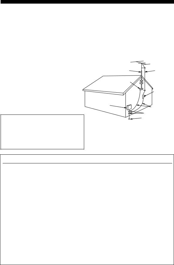
24Outdoor Antenna Grounding – If an outside antenna or cable system is connected to the product, be sure the antenna or cable system is grounded so as to provide some protection against voltage surges and built-up static charges. Article 810 of the National Electrical Code, ANSI/NFPA 70, provides information with regard to proper grounding of the mast and supporting structure, grounding of the lead-in wire to an antenna discharge unit, size of grounding conductors, location of antenna discharge unit, connection to grounding electrodes, and requirements for the grounding electrode.
EXAMPLE OF ANTENNA GROUNDING
MAST |
ANTENNA |
|
LEAD IN |
|
WIRE |
GROUND |
|
CLAMP |
|
|
ANTENNA |
|
DISCHARGE UNIT |
|
(NEC SECTION 810–20) |
ELECTRIC |
|
SERVICE |
|
EQUIPMENT |
GROUNDING CONDUCTORS |
|
|
|
(NEC SECTION 810–21) |
|
GROUND CLAMPS |
|
POWER SERVICE GROUNDING |
|
ELECTRODE SYSTEM |
|
(NEC ART 250. PART H) |
NEC – NATIONAL ELECTRICAL CODE |
|
FCC INFORMATION (for US customers)
1IMPORTANT NOTICE: DO NOT MODIFY THIS UNIT!
This product, when installed as indicated in the instructions contained in this manual, meets FCC requirements. Modifications not expressly approved by Yamaha may void your authority, granted by the FCC, to use the product.
2IMPORTANT: When connecting this product to accessories and/or another product use only high quality shielded cables. Cable/s supplied with this product MUST be used. Follow all installation instructions. Failure to follow instructions could void your FCC authorization to use this product in the USA.
3NOTE: This product has been tested and found to comply with the requirements listed in FCC Regulations, Part 15 for Class “B” digital devices. Compliance with these requirements provides a reasonable level of assurance that your use of this product in a residential environment will not result in harmful interference with other electronic devices.
This equipment generates/uses radio frequencies and, if not installed and used according to the instructions found in the users manual, may cause interference harmful to the operation of other electronic devices.
Compliance with FCC regulations does not guarantee that interference will not occur in all installations. If this product is found to be the source of interference, which can be determined by turning the unit “OFF” and “ON”, please try to eliminate the problem by using one of the following measures:
Relocate either this product or the device that is being affected by the interference.
Utilize power outlets that are on different branch (circuit breaker or fuse) circuits or install AC line filter/s.
In the case of radio or TV interference, relocate/reorient the antenna. If the antenna lead-in is 300 ohm ribbon lead, change the lead-in to coaxial type cable.
If these corrective measures do not produce satisfactory results, please contact the local retailer authorized to distribute this type of product. If you can not locate the appropriate retailer, please contact Yamaha Electronics Corp., U.S.A. 6660 Orangethorpe Ave, Buena Park, CA 90620.
The above statements apply ONLY to those products distributed by Yamaha Corporation of America or its subsidiaries.
ii
CAUTION: READ THIS BEFORE OPERATING YOUR UNIT.
1To assure the finest performance, please read this manual carefully. Keep it in a safe place for future reference.
2Install this unit (RX-E810 and DVD-E810) in a well ventilated, cool, dry, clean place with at least 10 cm on the top (2.5 cm for DVD-E810), 10 cm on the left and right, and 10 cm at the back of this unit — away from direct sunlight, heat sources, vibration, dust, moisture, and/or cold.
3Locate this unit away from other electrical appliances, motors, or transformers to avoid humming sounds.
4Do not expose this unit to sudden temperature changes from cold to hot, and do not locate this unit in an environment with high humidity (i.e. a room with a humidifier) to prevent condensation inside this unit, which may cause an electrical shock, fire, damage to this unit, and/or personal injury.
5Avoid installing this unit where foreign object may fall onto this unit and/or this unit may be exposed to liquid dripping or splashing. On the top of this unit, do not place:
–Other components, as they may cause damage and/or discoloration on the surface of this unit.
–Burning objects (i.e. candles), as they may cause fire, damage to this unit, and/or personal injury.
–Containers with liquid in them, as they may fall and liquid may cause electrical shock to the user and/or damage to this unit.
6Do not cover this unit with a newspaper, tablecloth, curtain, etc. in order not to obstruct heat radiation. If the temperature inside this unit rises, it may cause fire, damage to this unit, and/or personal injury.
7Do not plug in this unit to a wall outlet until all connections are complete.
8Do not operate this unit upside-down. It may overheat, possibly causing damage.
9Do not use force on switches, knobs and/or cords.
10When disconnecting the power cable from the wall outlet, grasp the plug; do not pull the cable.
11Do not clean this unit with chemical solvents; this might damage the finish. Use a clean, dry cloth.
12Only voltage specified on this unit must be used. Using this unit with a higher voltage than specified is dangerous and may cause fire, damage to this unit, and/or personal injury. YAMAHA will not be held responsible for any damage resulting from use of this unit with a voltage other than specified.
13Do not attempt to modify or fix this unit. Contact qualified YAMAHA service personnel when any service is needed. The cabinet should never be opened for any reasons.
14When not planning to use this unit for long periods of time (i.e. vacation), disconnect the AC power plug from the wall outlet.
15Be sure to read the “Troubleshooting” section on common operating errors before concluding that this unit is faulty.
16Before moving this unit, press STANDBY/ON to set this unit in standby mode, and disconnect the AC power plug from the wall outlet.
17Condensation will form when the surrounding temperature changes suddenly. Disconnect the power cable from the outlet, then leave the unit alone.
18When using the unit for a long time, the unit may become warm. Turn the power off, then leave the unit alone for cooling.
19Install this unit near the wall outlet and where the AC power plug can be reached easily.
DANGER
When this unit is plugged to the wall outlet, do not place your eyes close to the opening of the disc tray and other openings to look into inside.
This unit is not disconnected from the AC power source as long as it is connected to the wall outlet, even if this unit itself is turned off. This state is called the standby mode. In this state, this unit is designed to consume a very small quantity of power.
The laser component in this product is capable of emitting radiation exceeding the limit for Class 1.
WARNING
TO REDUCE THE RISK OF FIRE OR ELECTRIC SHOCK, DO NOT EXPOSE THIS APPLIANCE TO RAIN OR MOISTURE.
FOR CANADIAN CUSTOMERS
To prevent electric shock, match wide blade of plug to wide slot and fully insert.
This Class B digital apparatus complies with Canadian ICES-003.
IMPORTANT
Please record the serial number of this unit in the space below.
MODEL:
Serial No.:
The serial number is located on the rear of the unit. Retain this Owner’s Manual in a safe place for future reference.
We Want You Listening For A Lifetime
YAMAHA and the Electronic Industries Association’s Consumer Electronics Group want you to get the most out of your equipment by playing it at a safe level. One that lets the sound come through loud and clear without annoying blaring or distortion – and, most importantly, without affecting your sensitive hearing. Since hearing damage from loud sounds is often undetectable until it is too late, YAMAHA and the Electronic Industries Association’s Consumer Electronics Group recommend you to avoid prolonged exposure from excessive volume levels.
iii

Contents
INTRODUCTION |
|
Features .................................................................. |
2 |
Supplied Accessories ............................................. |
2 |
Controls and Functions......................................... |
3 |
Receiver (RX-E810) .................................................. |
3 |
DVD player (DVD-E810).......................................... |
6 |
Remote control........................................................... |
8 |
PREPARATION |
|
Connecting the System ........................................ |
12 |
Connecting a TV .................................................. |
14 |
Connecting Antennas .......................................... |
15 |
Connecting the AM loop antenna ............................ |
15 |
Connecting the FM antenna..................................... |
15 |
Connecting External Components ..................... |
16 |
Connecting an MD player or a tape deck ................ |
16 |
Connecting an MD recorder or a CD recorder ........ |
16 |
Connecting a YAMAHA iPod universal dock ........ |
17 |
Connecting the Power Cables............................. |
18 |
Setting the System................................................ |
19 |
Step 1: Turn on the power and select |
|
the DVD input ..................................................... |
19 |
Step 2: Adjust the clock........................................... |
19 |
Step 3: Set the aspect ratio....................................... |
20 |
Step 4: Set the OSD language.................................. |
20 |
Step 5: Set the the default audio, subtitle, |
|
and disc menu languages ..................................... |
21 |
BASIC OPERATIONS |
|
Basic Receiver Operations .................................. |
22 |
Changing the front panel display settings................ |
23 |
Supported Disc Types.......................................... |
24 |
Basic Disc Playback Operations......................... |
25 |
Repeating disc playback (Repeat Play) ................... |
26 |
Playing back randomly (Shuffle Play)..................... |
26 |
Specifying an elapsed time for playback |
|
(Time Search) ...................................................... |
27 |
Specifying a preview picture for playback |
|
(Scan Search)....................................................... |
28 |
Customizing playback order (Program Play) .......... |
29 |
Selecting audio and subtitle languages/ |
|
audio channel settings. ........................................ |
30 |
Zooming the picture................................................. |
30 |
Selecting a viewing angle ........................................ |
31 |
Operating the disc menu .......................................... |
31 |
Playing back MP3/WMA/JPEG/DivX discs ........... |
32 |
Viewing or changing playback settings on the TV |
|
(OSD menu) ........................................................ |
34 |
Restricting Disc Playback ................................... |
35 |
Setting the parental control level ............................. |
35 |
Locking a disc.......................................................... |
36 |
Changing the password............................................ |
36 |
TUNER OPERATIONS |
|
FM/AM Tuning .................................................... |
37 |
Automatic tuning ..................................................... |
37 |
Manual tuning.......................................................... |
37 |
Automatic preset tuning........................................... |
38 |
Manual preset tuning ............................................... |
39 |
Selecting preset stations........................................... |
39 |
Radio Data System Tuning |
|
(U.K. and Europe Models Only) ..................... |
40 |
Selecting the Radio Data System program .............. |
40 |
Displaying the Radio Data System information ...... |
41 |
OTHER OPERATIONS |
|
Setting the Timer.................................................. |
43 |
Setting the clock timer ............................................. |
43 |
Setting the sleep timer ............................................. |
44 |
Setting the auto-standby mode............................ |
45 |
Controlling External Components...................... |
46 |
Available operations ................................................ |
46 |
Setting remote control codes ................................... |
48 |
Using iPod ............................................................... |
49 |
Configuring the DVD Player Settings |
|
(Setup Menu) .................................................... |
51 |
Setup menu items..................................................... |
52 |
Resetting the DVD player settings .......................... |
56 |
ADDITIONAL INFORMATION |
|
Language Codes ................................................... |
57 |
Troubleshooting.................................................... |
58 |
Receiver (RX-E810) ................................................ |
58 |
DVD player (DVD-E810)........................................ |
61 |
Remote control ........................................................ |
62 |
Notes on Discs ....................................................... |
63 |
Disc information ...................................................... |
63 |
Handling a disc ........................................................ |
64 |
Glossary................................................................. |
65 |
Audio information ................................................... |
65 |
Video information.................................................... |
66 |
Copyright and logo marks ....................................... |
66 |
Specifications ........................................................ |
67 |
INTRODUCTION |
|
|
|
|
|
PREPARATION |
|
|
|
|
|
OPERATIONS |
BASIC |
|
|
|
|
OPERATIONS |
TUNER |
|
|
|
|
OPERATIONS |
OTHER |
|
|
|
|
INFORMATION |
ADDITIONAL |
|
|
English
1 En
Features
Receiver (RX-E810)
•Maximum RMS output power per channel 65W + 65W (6 Ω, 1 kHz, 1%THD)
•40-station FM/AM preset tuning
•iPod dock terminal
•Pure Direct mode
DVD player (DVD-E810)
•Plays DVDs, Video CDs, Audio CDs, MP3 CDs, WMA CDs, DivX CDs and JPEG CDs.
•Progressive-scan video output
•Optical and coaxial digital output jacks
■ About this manual
•In this manual, “RX-E810” is described as “receiver” and “DVD-E810” is described as “DVD player”.
•This manual describes how to operate the system using a remote control except when it is not available. Some of these operations are also available using the front panel buttons.
•Remote control descriptions and illustrations in this manual are based on the U.K. and Europe models unless otherwise specified.
•yindicates a tip for your operation.
•Notes contain important information about safety and operating instructions.
•This manual is printed prior to production. Design and specifications are subject to change in part as a result of improvements, etc. In case of differences between the manual and the product, the product has priority.
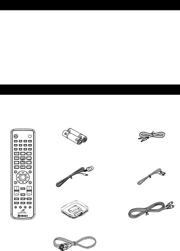
Supplied Accessories
This product includes the following accessories. Before connecting this system, make sure you received all of the following parts.
Remote |
Batteries (x2) |
System control |
control |
(AA, R06, UM-3) |
cable (0.6 m) |
STANDBY/ON |
|
|
|
|
POWER |
|
|
|
|
|
TV |
1 |
2 |
|
3 |
|
4 |
5 |
6 |
|
7 |
|
8 |
|
|
|
SCAN |
|
DIMMER |
9 |
0 |
|
|
|
|
|
|
REPEAT |
|
A-B |
|
TV CH |
|
|
|
FREQ/TEXT |
|
|
|
|
|
PROG |
|
|
|
MODE |
PTY SEEK |
START |
|
TV INPUT |
|
|
|
SHUFFLE |
|
ON SCREEN |
|
PRESET |
|
MENU |
|
INFO. |
|
|
|
|
|
A-E |
|
ENTER |
|
A-E |
|
SET UP |
|
|
|
|
TOP MENU |
|
|
|
|
/RETURN |
|
TV VOL |
|
|
|
VOLUME |
|
|
|
DISPLAY |
|
|
|
SLEEP
DVD/CD TUNER BAND
Indoor FM antenna |
Indoor FM antenna |
(U.S.A., Canada, China, Taiwan, |
(U.K., Europe, Australia, |
and Asia models) |
and Korea models) |
AM loop antenna |
Video pin |
|
cable (1.5 m) |
TAPE/MD AUX/TV DOCK
SUBTITLE ANGLE ZOOM AUDIO
Audio pin cable (1.5 m)
2 En
Controls and Functions
Receiver (RX-E810)
■ Front panel
1 2 |
3 4 5 |
6 |
7 |
8 |
|
9 |
||
|
|
NATURAL SOUND STEREO RECEIVER RX-E810 |
|
|
||||
|
|
|
|
|
|
|
|
PURE DIRECT |
TIMER |
DISPLAY |
MEMORY |
AUTO/MAN'L |
PRESET/BAND |
|
PRESET/TUNING |
|
|
|
|
|
|
|
|
|
|
VOLUME |
|
|
TIME ADJ |
TIMER |
|
|
HOUR |
MIN |
|
STANDBY/ON |
BASS |
|
TREBLE |
BALANCE |
|
|
INPUT |
|
|
|
|
|
|
||||
|
PHONES |
|
|
|
|
|
|
|
|
|
|
|
L |
R |
|
|
|
|
|
|
|
|
|
|
MIN |
MAX |
0 A B |
C |
D |
E |
F |
1 STANDBY/ON
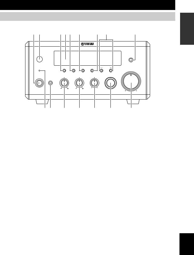
Turns the receiver on or sets it to the standby mode (see page 19).
2 Remote control sensor
Receives signals from the remote control.
3 DISPLAY
Switches the information shown in the front panel display (see page 23).
4 Front panel display
Shows the various infomaiton such as the clock time or the tuning frequency.
5 MEMORY (TIME ADJ)
•Stores a preset station in the memory. Hold down this key for more than 2 seconds to preset radio stations automatically (see page 38).
•Sets the clock before using the timer function (see page 19).
6 AUTO/MAN’L (TIMER)
•Switches between Auto Tuning mode and Manual Tuning mode when tuner is selected as an input source (see
page 37).
•Turns the clock timer function on or off (see page 43).
7 PRESET/BAND
Switches between FM, AM, and the preset mode when tuner is selected as an input source.
8PRESET/TUNING d/ u(HOUR, MIN)
Selects a tuning frequency when tuner is selected as an input source.
9PURE DIRECT
Turns on or off the Pure Direct mode (see page 22).
0 TIMER LED
Lights up when the clock timer is on (see page 43).
A PHONES
Outputs audio signals for private listening with headphones.
B BASS
Adjusts the low frequency responce (see page 22).
C TREBLE
Adjusts the high frequency responce (see page 22).
D BALANCE
Adjusts the volume level of each left and right speaker channel (see page 22).
E INPUT
Selects an input source.
F VOLUME
Adjusts the volume level.
INTRODUCTION
English
3 En
Controls and Functions
■ Rear panel
1 2 3
(Europe model)
MAINS
ANTENNA SPEAKERS
75
UNBAL.
DOCK |
6 MIN / SPEAKER |
|
|
DVD/CD |
FM |
|
|
AC OUTLETS |
|
|
|
|
|
|
|
|
|
|
|
|
|
SWITCHED |
|
|
|
R |
L |
|
|
|
|
|
GND |
|
|
|
|
|
IN |
|
|
|
|
|
|
TAPE/MD |
|
|
|
|
|
|
OUT |
AM |
|
|
|
|
|
|
|
SUBWOOFER |
TO DVD-E810 |
|
|
|
|
|
OUT |
|
|
|
|
AUX |
|
|
|
100W MAX. TOTAL |
|
|
|
|
|
|
|
|
|
R |
L |
|
|
|
4 |
5 |
6 |
|
7 |
8 |
9 |
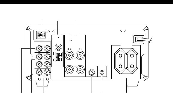
1 DOCK terminal
Use to connect a YAMAHA iPod universal dock (such as YDS-10 sold separately) where your iPod can be stationed (see page 17).
2 Antenna terminals
See page 15 for connection information.
3 Speaker terminals
See page 13 for connection information.
4 DVD/CD jacks
See page 12 for connection information.
5 TAPE/MD IN/OUT jacks
See page 16 for connection information.
6 AUX jacks
Use to connect the external components.
7SUBWOOFER OUT jack
Use to connect the subwoofer.
8System connector (TO DVD-E810) jack
See page 12 for connection information.
9AC OUTLET(S)
See page 18 for connection information.
4 En

Controls and Functions
■ Front panel display
1 |
2 |
3 |
4 |
5 |
6 |
7 |
8 |
|
|
|
|||||||||
|
|
|
|
|
|
|
|
|
|
|
|
|
|
|
|
|
|
|
|
SLEEP PRESET STEREO AUTO |
DOCK SHUFFLE REPEAT |
|
PS PTY RT CT PTY HOLD |
||||||||||||||||
TIMER |
TUNED MEMORY |
|
|
PLAYLISTS ARTISTS ALBUMS SONGS GENRES |
|
||||||||||||||
|
|
|
|
D |
9 |
0 |
A |
B |
C |
INTRODUCTION
1 SLEEP indicator
Lights up when the sleep timer is on (see page 44).
2 PRESET indicator
Lights up when you preset radio stations manually (see page 39).
3 STEREO indicator
Lights up when the receiver is receiving a strong signal from an FM stereo broadcast.
4 AUTO indicator
Lights up when the receiver is in the Auto Tuning mode (see page 38).
5 DOCK indicator
Lights up when you station your iPod in a YAMAHA iPod universal dock (such as YDS-10 sold separately) connected to the DOCK terminal of the receiver (see page 17).
6 SHUFFLE indicator
Lights up when you set your iPod in shuffle mode.
7 REPEAT indicator
Lights up when you set your iPod in repeat mode.
8 Radio Data System indicators (U.K. and Europe models only)
The name of the Radio Data System data offered by the currently received Radio Data System station lights up.
PTY HOLD indicator
Lights up when the receiver is seaching for the Radio Data System stations in the PTY SEEK mode (see page 40).
9 Multi-information display
Shows the various infomaiton such as the clock time or the tuning frequency.
0 TIMER indicator
Flashes when the the receiver is in the clock timer setting mode (see page 43).
A TUNED indicator
Lights up when the receiver is tuned into a station.
B MEMORY indicator
Lights up or flashes when you preset radio stations.
C iPod menu indicators
Light up the iPod menu currently selected (see page 49).
D iPod operation indicators
Show operable cursor keys when operating the iPod menu with the menu browse mode (see page 49).
English
5 En
Controls and Functions
DVD player (DVD-E810)
■ Front panel
|
1 |
|
2 |
3 |
4 |
|
|
NATURAL SOUND DVD PLAYER DVD-E810 |
|
|
|
STANDBY/ON |
|
|
|
|
|
|
PROGRESSIVE |
|
|
|
|
5 |
6 |
7 |
8 |
9 |
0 |
1 Disc tray
Holds a disc to be played back.
2 
Opens and closes the disc tray.
3 s
Stops playback (see page 25).
4 h/e
Starts or pauses playback (see page 25).
5 STANDBY/ON
Turns the DVD player on or sets it to the standby mode (see page 22).
6 PROGRESSIVE indicator
Lights up when the progressive scan mode is on (see page 54).
7 Front panel display
Shows the current status of the DVD player.
8 Remote control sensor
Receives signals from the remote control.
9 b/w
Skips to the begining of the current chapter/track. Press and hold to fast reverse (see page 25).
0 f/a
Skips to the next chapter/track. Press and hold to fast forward (see page 25).
6 En
Controls and Functions
■ Rear panel
MAINS
1 (U.K. and Europe models only)
AV
VIDEO OUT |
DIGITAL OUT |
AUDIO |
COMPONENT |
OUT |
|
|
||
PR |
Y |
L |
|
||
|
COAXIAL OPTICAL |
|
TO RX-E810
S VIDEO |
VIDEO |
PB |
|
|
R |
2 |
3 |
4 |
5 |
6 |
7 8 |
1 |
AV terminal (U.K. and Europe models only) |
5 |
COAXIAL jack |
See page 14 for connection information. |
See page 16 for connection information. |
||
2 |
S VIDEO jack |
6 |
OPTICAL jack |
See page 14 for connection information. |
See page 16 for connection information. |
||
3 |
VIDEO jack |
7 |
AUDIO OUT jacks |
See page 14 for connection information. |
See page 12 for connection information. |
||
4 |
COMPONENT jacks |
8 |
System connector (TO RX-E810) jack |
See page 14 for connection information. |
See page 12 for connection information. |
||
INTRODUCTION
English
7 En
Controls and Functions
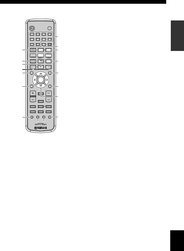
Remote control
DVD/CD |
TUNER |
• Playback |
• Radio station |
• Subtitle and |
tuning |
audio language |
• Radio station |
selection, etc. |
preset, etc. |
DVD/CD mode |
|
|
TUNER mode |
STANDBY/ON |
|
|
POWER |
|
|
|
TV |
1 |
2 |
3 |
4 |
5 |
6 |
7 |
8 |
|
|
SCAN DIMMER |
|
9 |
0 |
|
|
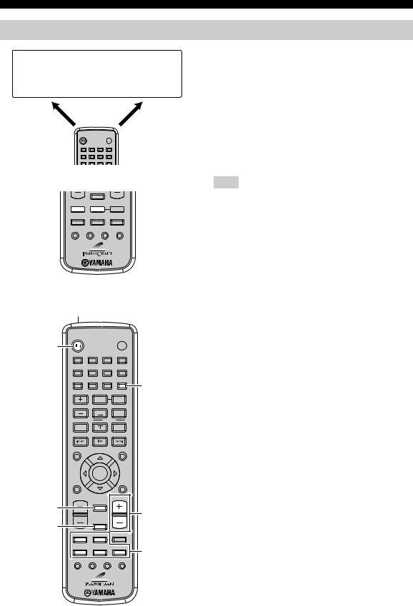
This remote control has two main operation modes to control this system. Before operating functions in each mode, you need to select a mode to change the remote control key assignments.
To switch the operation mode
•DVD/CD mode: Press DVD/CD.
•TUNER mode: Press TUNER.
y
You can also operate the TV and other components (such as an iPod) connected to the receiver using the remote control. For details, see “Controlling External Components” on page 46.
SLEEP
DVD/CD TUNER BAND
DVD/CD 


 TUNER
TUNER
TAPE/MD AUX/TV DOCK
SUBTITLE ANGLE ZOOM AUDIO
■ Common functions
1
STANDBY/ON |
POWER |
2 |
|
|
|
|
TV |
1 |
2 |
|
3 |
|
4 |
5 |
6 |
|
7 |
|
8 |
|
|
|
SCAN |
|
DIMMER |
9 |
0 |
|
|
|
5 |
|
|
REPEAT |
|
A-B |
|
TV CH |
|
|
|
FREQ/TEXT |
|
|
|
|
|
|
PROG |
|
|
MODE |
PTY SEEK |
START |
|
|
|
|
|
||
TV INPUT |
|
|
|
SHUFFLE |
|
ON SCREEN |
|
PRESET |
|
MENU |
|
INFO. |
|
|
|
|
|
A-E |
|
ENTER |
|
A-E |
|
SET UP |
|
|
|
|
TOP MENU |
|
|
|
|
/RETURN |
|
TV VOL |
|
VOLUME |
3 |
DISPLAY |
|
|
6 |
|
|
|
|
4 |
SLEEP |
|
|
|
|
DVD/CD |
TUNER |
BAND |
TAPE/MD |
AUX/TV |
DOCK |
7 |
|
|
|
|
SUBTITLE |
ANGLE ZOOM |
AUDIO |
|
Note
Remote control descriptions and illustrations in this manual are based on the U.K. and Europe models unless otherwise specified.
Operations common to all modes
The following operations are available for the receiver when the remote control is in any operation modes.
1 Infrared signal transmitter
Sends signals to the component you want to control.
2 STANDBY/ON (
 )
)
Turns the receiver on or sets it to the standby mode (see page 19).
3 DISPLAY
Switches the information shown in the front panel display (see page 23).
4 SLEEP
Sets the sleep timer on the receiver (see page 44).
5 DIMMER
Changes the brightness of the receiver’s front panel display (see page 23).
6 VOLUME +/–
Adjusts the overall volume level on the receiver.
7 Input selection keys
Select the input source on the receiver.
y
STANDBY/ON, DIMMER and SLEEP operations also control the DVD player when the DVD player is connected to the receiver with the supplied system control cable (see page 12).
8 En
■ DVD/CD mode
STANDBY/ON |
|
|
POWER |
|
|
|
|
TV |
|
1 |
2 |
3 |
4 |
0 |
|
|
|
|
|
5 |
6 |
7 |
8 |
|
|
|
SCAN |
DIMMER |
|
9 |
0 |
|
|
A |
1 |
|
|
|
|
|
REPEAT |
A-B |
B |
|
TV CH |
|
|
FREQ/TEXT |
|
2

 PROG
PROG 
 C
C
|
MODE |
PTY SEEK |
START |
|
3 |
TV INPUT |
SHUFFLE |
D |
|
|
|
|
||
4 |
|
|
|
|
5 |
ON SCREEN |
PRESET |
MENU |
E |
6 |
|
|
|
|
|
INFO. |
|
|
|
|
A-E |
ENTER |
A-E |
|
|
SET UP |
|
TOP MENU |
|
7 |
|
/RETURN |
F |
|
|
|
|
||
|
TV VOL |
|
VOLUME |
|
|
|
DISPLAY |
|
|
|
|
|
|
G |
|
|
SLEEP |
|
|
|
DVD/CD |
TUNER |
BAND |
|
|
TAPE/MD |
AUX/TV |
DOCK |
|
8 |
SUBTITLE |
ANGLE ZOOM |
AUDIO |
H |
9
 I
I
Operations available in DVD/CD mode
The following operations are available for the DVD player.
y
Press DVD/CD to set the remote control to the DVD/CD mode before carrying out the following operations.
1 REPEAT
Selects the Repeat Play mode (see page 26).
2 s
Stops playback (see page 25).
3 e
Pauses playback (see page 25).
4 h
Starts playback (see page 25).
5 b, a
Skips to the beginning of the current chapter/track or next chapter/track. Press and hold to fast reverse or fast forward (see page 25).
6 ON SCREEN (INFO.)
Displays the OSD menu on the TV screen or switches the time display of CDs (see page 34).
Controls and Functions
7 SET UP
Displays the setup menu on the TV screen (see page 51).
8 SUBTITLE
Selects the subtitle language (see page 30).
9 ANGLE
Selects a viewing angle (see page 31).
0 Number keys (1 to 9, 0)
Input numerals to specify parameters or chapter/track numbers.
A SCAN
Previews the content of a DVD or VCD (see page 28) or plays back the first few seconds of each track on a CD (see page 25).
B A-B
Repeats a specified section within a chapter/track (see page 26).
C PROG
Displays the program list used for the Program Play feature (see page 29).
D SHUFFLE
Turns on/off the Shuffle Play feature (see page 26).
E MENU
Displays the DVD menu (see page 31) or PBC menu of a VCD (see page 31).
F TOP MENU/RETURN
Returns to the top of the DVD menu (see page 31) or to the previous PBC menu (see page 31). Press and hold to return to the previous DVD menu.
G Cursor keys ( /
/  /
/  /
/  ), ENTER
Selects an item in the menu screen or specify the selected parameter.
H AUDIO
Selects the audio language (see page 30).
I ZOOM
Zooms in a specified part of picture (see page 30).
INTRODUCTION
English
9 En

Controls and Functions |
|
■ TUNER mode |
Operations available in TUNER mode |
STANDBY/ON |
POWER |
|
TV |
The following operations are available for the receiver.
y
Press TUNER to set the remote contol to the TUNER mode before carrying out the following operations.
1 |
2 |
3 |
4 |
5 |
6 |
7 |
8 |
|
|
SCAN |
DIMMER |
9 |
0 |
|
|
|
REPEAT |
|
A-B |
|
TV CH |
|
|
FREQ/TEXT |
|
|
|
|
|
PROG |
|
MODE |
PTY SEEK |
START |
|
|
|
|
||
TV INPUT |
|
|
SHUFFLE |
|
ON SCREEN |
PRESET |
|
MENU |
|
1Number keys (1 to 8)
1Selects preset station number (see page 39).
2Radio Data System tuning keys (U.K. and Europe models only)
2
FREQ/TEXT
Switches the Radio Data System display between the PS mode, PTY mode, RT mode, CT mode (if the station offers the corresponding data services) and the frequency display (see page 41).
INFO. |
|
|
|
A-E |
ENTER |
A-E |
|
SET UP |
|
TOP MENU |
|
|
/RETURN |
|
|
TV VOL |
|
VOLUME |
|
|
DISPLAY |
|
|
|
|
|
3 |
|
SLEEP |
|
|
DVD/CD |
TUNER |
BAND |
4 |
|
|
|
|
TAPE/MD |
AUX/TV |
DOCK |
|
SUBTITLE |
ANGLE ZOOM |
AUDIO |
|
PTY SEEK MODE
Sets the receiver to the PTY SEEK mode (see page 40).
PTY SEEK START
Starts searching for a station once the desired program type is selected in the PTY SEEK mode (see page 40).
3 A-E |
/ |
|
, PRESET |
/ |
||
Press A-E |
|
/ |
|
to select a preset station group (A to E) |
||
|
|
|
|
|
|
|
and PRESET |
|
/ |
to select a preset station number |
|||
(1 to 8) (see page 39). |
|
|
||||
4 BAND
Switches the radio reception mode between FM, AM and the preset mode.
10 En
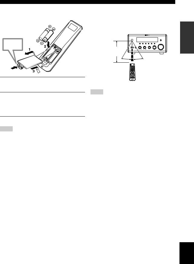
■Installing the batteries in the remote control
Press 
Controls and Functions
■ Using the remote control
Use the remote control within 6 m (20 feet) of the component you want to control and point it toward its remote control sensor (see pages 3 and 6).
|
NATURAL SOUND STEREO RECEIVER RX-E810 |
|
||
|
|
|
|
PURE DIRECT |
TIMER |
DISPLAY MEMORY |
AUTO/MAN'L PRESET/BAND |
PRESET/TUNING |
|
|
|
|
VOLUME |
|
|
TIME ADJ |
TIMER |
HOUR MIN |
|
STANDBY/ON |
BASS |
TREBLE BALANCE |
INPUT |
|
Within 6 m |
PHONES |
|
|
|
|
L |
MIN |
MAX |
|
|
|
R |
|
|
(20 feet) |
|
|
|
|
30˚ |
30˚ |
|
|
|
1Press the  mark on the battery cover and open the cover.
2Insert the two supplied batteries (AA, R06, UM-3) into the battery compartment.
Make sure you insert the batteries according to the polarity markings (+ and –).
3Close the battery cover.
Notes
•Do not use an old battery together with new one.
•Do not use different types of batteries (for example, alkaline and manganese) together. Each type of battery has its own characteristics even if they are similar in shape.
•If the batteries run out, immediately remove them from the remote control to prevent an explosion or acid leak.
•Dispose of the batteries according to the regional regulations.
•If a battery starts leaking, dispose of it immediately. Be careful not to let leaking battery acid come into contact with your skin or clothing. Before inserting new batteries, wipe the compartment clean.
•Replace the batteries within two minutes to preserve the memory in the remote control.
Notes
•Be careful not to spill liquid on the remote control.
•Be careful not to drop the remote control.
•Do not leave the remote control in the following places:
–hot or humid places, such as near a heater or in a bathroom
–extremely cold places
–dusty places
INTRODUCTION
English
11 En
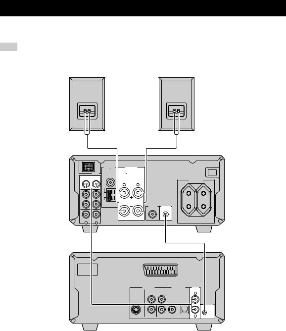
Connecting the System
Make sure you read the following procedure and notes carefully before connecting the system. For information on the speakers (NX-E800), refer to the owner’s manual supplied with it.
Note
Do not connect the power cable of the receiver, DVD player, or other components to the wall outlet until all cable connections are completed.
Right speaker (NX-E800)
3 |
|
|
|
|
|
ANTENNA |
SPEAKERS |
|
|
75 |
|
DOCK |
UNBAL. |
|
|
6 |
MIN / SPEAKER |
||
DVD/CD |
|
FM |
|
|
|
R |
L |
|
|
GND |
|
IN |
|
|
|
TAPE/MD |
|
|
|
OUT |
|
AM |
|
AUX |
|
|
|
R |
L |
|
|
1 |
|
|
|
MAINS |
|
|
|
Left speaker (NX-E800)
3
SUBWOOFER |
TO DVD-E810 |
OUT |
|
MAINS |
AC OUTLETS |
SWITCHED |
100W MAX. TOTAL |
Receiver (RX-E810)
(Europe model)
2
AV
|
VIDEO OUT |
DIGITAL OUT |
AUDIO |
|
COMPONENT |
OUT |
|
|
PR |
Y |
L |
|
|
||
|
|
COAXIAL OPTICAL |
|
|
|
|
TO RX-E810 |
S VIDEO |
VIDEO |
PB |
R |
DVD player (DVD-E810)
1 Connect the DVD/CD (L/R) jacks of the receiver to the AUDIO OUT (L/R) jacks of the DVD player using the supplied audio pin cable.
2 Connect the system connector (TO DVD-E810) jack of the receiver to the system connector (TO RX-E810) jack of the DVD player using the supplied system control cable.
3 Connect the speaker terminals (L) of the receiver to the speaker terminals of the left speaker and the speaker terminals
(R) of the receiver to the speaker terminals of the right speaker using the speaker cables supplied with the speaker set (NX-E800). See page 13 for details.
y
•The system control connection is used to synchronize the specific operations between the receiver and the DVD player.
•If you want to connect an amplifier with a digital input instead of the RX-E810, use the DIGITAL OUT (COAXIAL or OPTICAL) jacks of the DVD player and configure the “DIGITAL OUTPUT” setting in the setup menu (see page 52).
12 En

Connecting the System
■ Connecting the speaker cable
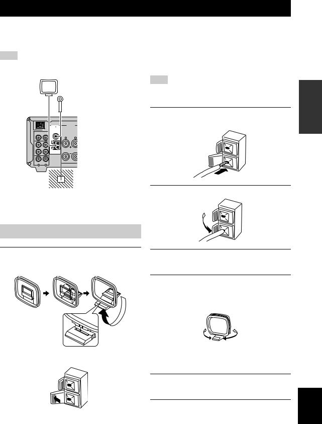
4 Tighten the knob to secure the wire.
Notes
•Be sure to connect the left channel (L), right channel (R), “+” (red) and “–” (black) properly. If the connections are faulty, no sound will be heard from the speakers, and if the polarity of the speaker connections is incorrect, the sound will be unnatural and lack bass.
•Do not let the bare speaker wires touch each other or do not let them touch any metal part of the receiver. This could damage the receiver and/or the speakers.
•When connecting another speaker set instead of the NX-E800, be sure to use speakers with the specified impedance shown on the rear panel of the receiver and magnetically shielded. In case the magnetically shielded speakers interfere with the monitor, place the speakers away from the monitor.
Red: positive (+) Black: negative (–)
1Remove approximately 10 mm (3/8 in) of insulation from the end of each speaker cable and then twist the exposed wires of the cable together to prevent short circuits.
10 mm (3/8 in)
PREPARATION
2 Unscrew the knob.
Red: positive (+)
Black: negative (–)
3 Insert the bare wire into the terminal.
Red: positive (+)
Black: negative (–)
English
13 En
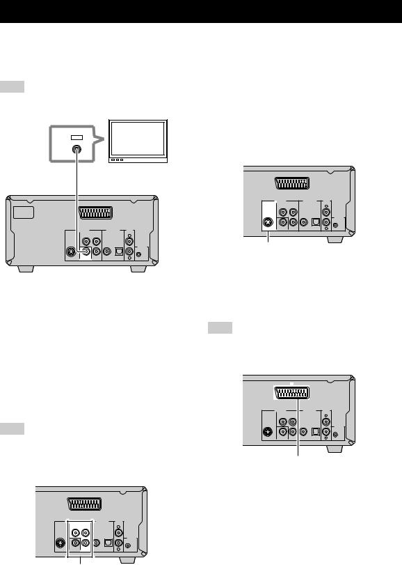
Connecting a TV
Follow the procedure below to connect your TV to the DVD player using the supplied video pin cable. Also, you can enjoy high-quality pictures with a S-video connection, a component video connection or a scart connection (U.K. and Europe models only) using a corresponding commercially available cable. For information on your TV, refer to the owner’s manual supplied with it.
Note
Do not connect the power cable of the receiver, DVD player, or other components to the wall outlet until all cable connections are
completed.
IN
VIDEO
Video pin cable |
TV |
(supplied) |
|
MAINS |
|
AV |
|
|
VIDEO OUT |
DIGITAL OUT |
AUDIO |
|
COMPONENT |
OUT |
|
|
PR |
Y |
L |
|
|
||
|
|
COAXIAL OPTICAL |
|
|
|
|
TO RX-E810 |
S VIDEO |
VIDEO |
PB |
R |
DVD player
Connect the VIDEO jack of the DVD player to the video input jack of your TV using the supplied video pin cable.
y
To enjoy TV sounds with the receiver, connect AUX (L/R) jacks of the receiver to the audio output jacks of your TV using a commercially available audio pin cable.
■ S-video connection
Connect the S VIDEO jack of the DVD player to the S-video input jack of your TV using a commercially available S-video cable.
|
|
AV |
|
|
|
VIDEO OUT |
|
DIGITAL OUT |
AUDIO |
|
COMPONENT |
|
OUT |
|
|
PR |
Y |
|
L |
|
|
|
||
|
|
|
COAXIAL OPTICAL |
|
|
|
|
|
TO RX-E810 |
S VIDEO |
VIDEO |
PB |
|
R |
S VIDEO jack
■ Scart connection
(U.K. and Europe models only)
Connect the AV terminal of the DVD player to the scart input terminal of your TV using a commercially available scart cable.
Note
(U.K. and Europe models only)
When you make a scart connection, set “COMPONENT” to “RGB” in the setup menu of the DVD player (see page 54).
■ Component video connection
Connect the COMPONENT jacks of the DVD player to the component video input jacks of your TV using a commercially available component video cable.
Note
(U.K. and Europe models only)
When you make a component video connection, set “COMPONENT” to “YUV” in the setup menu of the DVD player (see page 54).
|
|
AV |
|
|
|
|
VIDEO OUT |
|
DIGITAL OUT |
AUDIO |
|
|
COMPONENT |
|
|
OUT |
|
|
PR |
Y |
|
|
L |
|
|
|
|
||
|
|
|
COAXIAL |
OPTICAL |
|
|
|
|
|
|
TO RX-E810 |
S VIDEO |
VIDEO |
PB |
|
|
R |
COMPONENT jacks
|
|
AV |
|
|
|
|
VIDEO OUT |
|
DIGITAL OUT |
AUDIO |
|
|
COMPONENT |
|
|
OUT |
|
|
PR |
Y |
|
|
L |
|
|
|
COAXIAL |
OPTICAL |
|
|
|
|
|
|
TO RX-E810 |
S VIDEO |
VIDEO |
PB |
|
|
R |
AV terminal
(U.K. and Europe models only)
14 En
Connecting Antennas
To enjoy radio on the receiver, connect the supplied AM and FM antennas to the designated terminals. If there is a problem of weak radio wave reception in your area or you want to improve radio reception, we recommend that you use optional outdoor antennas. For details, consult the nearest authorized YAMAHA dealer or service center.
Note
Be sure to set the tuner frequency step (Asia and Taiwan models only) according to the frequency spacing in your area (see page 38).
AM loop antenna (supplied)
Indoor FM antenna (supplied)
|
|
ANTENNA |
SPEAKERS |
|
|
75 |
|
|
DOCK |
UNBAL. |
|
|
6 |
MIN / SPEAKER |
|
|
DVD/CD |
FM |
|
|
|
R |
L |
|
|
GND |
|
IN |
|
|
|
TAPE/MD |
|
|
|
OUT |
|
AM |
|
|
AUX |
|
|
R |
L |
|
|
Ground
(GND terminal)
■ About grounding
For maximum safety and minimum interference, connect the antenna GND terminal to a good earth ground. A good earth ground is a metal stake driven into moist earth.
Connecting the AM loop antenna
Note
Depending on the product, the shape of the tab is different from the described illust.
3Insert the AM loop antenna lead wires into the AM terminal.
4 Replace the tab back to secure the wire.
PREPARATION
1Attach the antenna stand to the antenna.
When attaching the antenna to the wall, you do not need to use the antenna stand.
5Repeat steps 2 to 4 to insert the AM loop antenna lead wires into the GND terminal.
6Place the antenna away from the receiver and speaker cables.
While listening to the radio, rotate the antenna head to find the best angle for reception.
|
|
Connecting the FM antenna |
2 Press down the tab of the AM terminal. |
|
1 Connect the supplied indoor FM antenna to the FM jack of the receiver.
2 Place the antenna away from the receiver and speaker cables.
English
15 En
Connecting External Components
You can connect various audio components, such as an MD player, a tape deck or a YAMAHA iPod universal dock to the receiver. Also you can connect an MD recorder or a CD recorder to the DVD player using the DIGITAL OUT jacks. For information on your external component, refer to the owner’s manual supplied with each component.
Note
Do not connect the power cable of the receiver, DVD player, or other components to the wall outlet until all cable connections are completed.
Connecting an MD player or a tape deck
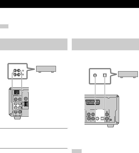
If you connect an MD player or a tape deck to the receiver, you can enjoy audio sources played on the component.
ANALOG
IN |
OUT |
|
L |
|
R |
MD player or |
|
|
tape deck |
|
Audio pin cable |
|
|
ANTENNA |
|
|
75 |
|
|
UNBAL. |
|
DOCK |
|
|
DVD/CD |
FM |
|
|
GND |
|
IN |
|
|
TAPE/MD |
|
|
OUT |
AM |
|
AUX |
|
|
R |
L |
|
Receiver
1Connect the TAPE/MD IN (L/R) jacks of the receiver to the analog output jacks of an MD player or a tape deck using a commercially available audio pin cable.
2To record audio output from the receiver, connect the TAPE/MD OUT (L/R) jacks of the receiver to the analog input jacks of an MD player or a tape deck using a commercially available audio pin cable.
Connecting an MD recorder or a CD recorder
If you connect an MD recorder or a CD recorder to the DVD player with a digital connection, you can make a digital recording.
COAXIAL OPTICAL
or
MD recorder or
CD recorder
Coaxial cable |
Optical cable |
|
|
AV |
|
VIDEO OUT |
|
DIGITAL OUT AUDIO |
COMPONENT |
OUT |
|
PR |
Y |
L |
|
||
|
|
COAXIAL OPTICAL |
|
|
TO RX-E810 |
VIDEO |
PB |
R |
DVD player
Connect the DIGITAL OUT (COAXIAL or OPTICAL) jack of the DVD player to the digital input (coaxial or optical) jack of an MD recorder or a CD recorder using a commercially available coaxial or optical cable.
Notes
•The DIGITAL OUT jacks are compatible with PCM, Dolby Digital and DTS signals.
•The DIGITAL OUT (OPTICAL) jack is designed based on EIA standards. To make a digital connection, use an optical cable that meets EIA standards.
16 En
Connecting External Components
Connecting a YAMAHA iPod universal dock
The receiver (RX-E810) is equipped with the DOCK terminal on the rear panel that allows you to connect a YAMAHA iPod universal dock (such as YDS-10 sold separately) where you can station your iPod and control playback of your iPod using the supplied remote control. Connect a YAMAHA iPod universal dock (such as YDS-10 sold separately) to the DOCK terminal on the rear of the receiver using its dedicated cables. Once the connection is complete, station your iPod in the YAMAHA iPod universal dock.
iPod
YAMAHA iPod universal dock (such as YDS-10 sold separately)
|
|
|
|
MAINS |
|
ANTENNA |
SPEAKERS |
|
|
|
75 |
|
|
|
|
UNBAL. |
|
|
|
DOCK |
6 |
MIN / SPEAKER |
|
|
DVD/CD |
FM |
|
|
AC OUTLETS |
|
|
|
|
SWITCHED |
|
|
R |
L |
|
|
GND |
|
|
|
IN |
|
|
|
|
TAPE/MD |
|
|
|
|
OUT |
AM |
|
|
|
|
|
|
SUBWOOFER |
TO DVD-E810 |
|
|
|
OUT |
|
AUX |
|
|
|
100W MAX. TOTAL |
|
|
|
Receiver |
|
R |
L |
|
|
|
|
|
|
|
(Europe model) |
Notes
•Do not connect the power cable of the receiver, DVD player, or other components to the wall outlet until all cable connections are completed.
•Only iPod (Click and Wheel), iPod nano, and iPod mini are supported.
•You need a YAMAHA iPod universal dock (such as YDS-10 sold separately) and its dedicated cable compatible with the DOCK terminal of the receiver.
•Do not connect any iPod accessories (such as headphones, a wired remote control, or an FM transmitter) to your iPod when it is stationed in a YAMAHA iPod universal dock (such as YDS-10 sold separately).
•Unless your iPod is firmly stationed in a YAMAHA iPod universal dock (such as YDS-10 sold separately) connected to the DOCK terminal of the receiver, audio signals may not be output properly.
•Once the connection between your iPod and the receiver is complete and the receiver is set to DOCK mode (see page 47), “iPod connected” appears in the front panel display. If the connection between your iPod and the receiver fails, a status message appears in the front panel display. For a complete list of connection status message, see the iPod section in “Troubleshooting” on page 60.
•Your iPod battery is automatically charged when your iPod is stationed in a YAMAHA iPod universal dock (such as YDS-10 sold separately) connected to the DOCK terminal of the receiver as long as the receiver is turned on.
•Depending on the type of the iPod, you may need to insert one of the iPod adapters supplied with a YAMAHA iPod universal dock (such as YDS-10 sold separately) into the dock slot before you station your iPod.
PREPARATION
English
17 En

Connecting the Power Cables
Once all connections are complete, connect the power cable of the DVD player to the AC OUTLET(S) terminal on the rear of the receiver (or the AC wall outlet if the AC OUTLET(S) terminal is not available), and then plug the power cable of the receiver into the AC wall outlet.
MAINS
|
ANTENNA |
SPEAKERS |
|
|
|
75 |
|
|
|
DOCK |
UNBAL. |
6 |
MIN / SPEAKER |
|
|
|
|||
DVD/CD |
FM |
|
|
AC OUTLETS |
|
|
|
|
|
|
|
|
|
SWITCHED |
|
|
R |
L |
|
|
GND |
|
|
|
IN |
|
|
|
|
TAPE/MD |
|
|
|
|
OUT |
AM |
|
|
|
|
|
|
SUBWOOFER |
TO DVD-E810 |
|
|
|
OUT |
|
100W MAX. TOTAL
AUX
To the AC wall outlet
R L
MAINS |
AV |
Receiver (Europe model)
To AC OUTLET(S) on the rear panel of the receiver (or the AC wall outlet)
|
VIDEO OUT |
|
DIGITAL OUT |
AUDIO |
|
COMPONENT |
|
OUT |
|
|
PR |
Y |
|
L |
|
|
|
||
|
|
|
COAXIAL OPTICAL |
|
|
|
|
|
TO RX-E810 |
S VIDEO |
VIDEO |
PB |
|
R |
DVD player
■ AC OUTLET(S) (SWITCHED)
U.K. and Australia models |
..................................... 1 outlet |
Korea model ............................................................... |
None |
Other models ......................................................... |
2 outlets |
Use these outlet(s) to supply power to the DVD player or any connected components. Connect the power cable of your other components to these outlet(s). Power to these outlet(s) is supplied when the receiver is turned on. For information on the maximum power or the total power consumption of the components that can be connected to these outlet(s), see “Specifications” on page 67.
18 En

Setting the System
Before starting playback operation, follow the procedure below to configure the system settings.
Step 1: Turn on the power and |
Step 2: Adjust the clock |
select the DVD input |
DISPLAY HOUR MIN |
|
STANDBY/ON |
|
|
POWER |
STANDBY/ON |
|
|
TV |
1 |
2 |
3 |
4 |
5 |
6 |
7 |
8 |
|
|
SCAN |
DIMMER |
9 |
0 |
|
|
|
|
NATURAL SOUND STEREO RECEIVER RX-E810 |
|
|
|||
|
|
|
|
|
|
|
PURE DIRECT |
TIMER |
DISPLAY |
MEMORY |
AUTO/MAN'L |
PRESET/BAND |
PRESET/TUNING |
VOLUME |
|
|
|
|
|
|
|
|
|
|
|
TIME ADJ |
TIMER |
|
HOUR |
MIN |
|
STANDBY/ON |
BASS |
|
TREBLE |
BALANCE |
|
INPUT |
|
|
|
|
|
||||
|
PHONES |
|
|
|
|
|
|
|
|
|
|
L |
R |
|
|
|
|
|
|
|
|
MIN |
MAX |
|
SLEEP |
|
TIME ADJ PRESET/BAND |
DVD/CD |
TUNER |
BAND |
|
DVD/CD |
|
|
1 Press DISPLAY on the front panel of the |
TAPE/MD |
AUX/TV |
DOCK |
|
SUBTITLE |
ANGLE ZOOM |
AUDIO |
receiver. |
|
|
|
“Clock Time” appears in the front panel display for a |
|
|
|
few seconds, and then “Set Clock” appears. |
PREPARATION
1Turn on your TV and then press STANDBY/ ON to turn on the receiver.
If the DVD player is connected to the receiver with the system control cable, the DVD player turns on automatically. Otherwise, press STANDBY/ON on the front panel of the DVD player to turn on it.
The front panel display of each component lights up.
2Press DVD/CD to select “DVD/CD” as an input source.
3On your TV, select the input to which the DVD player is connected (EXT1, AV1, etc.). For details, refer to the manual supplied with your TV.
The default screen appears on the TV screen.
Note
If the picture is distorted on your TV, the color system (NTSC and PAL) setting of the DVD player may not match your TV.
To switch the color system setting in such case, press  and then AUDIO while the disc tray is open.
2Press TIME ADJ for about two seconds to enter the clock setting mode.
3To set the hour setting ahead, press HOUR repeatedly. To set the hour setting backward, press HOUR repeatedly while holding down PRESET/BAND.
4To set the minute setting ahead, press MIN repeatedly. To set the minute setting backward, press MIN repeatedly while holding down PRESET/BAND.
English
19 En
Loading...