


PADS SET
DTT3KSP/DTT3KSTD
SERVICE MANUAL
● PCY135 ● PCY155
● RHH135 |
• PCY135 |
● KP125 |
• PCY155 |
|
●TP100
●TP120SD
• RHH135
• TP100 |
• TP120SD |
• KP125 |
|
You must have a PCY135/PCY155 service manual (ED 011894 ) before servicing the PCY135/PCY155.
You must have a RHH135 service manual (ED 011895 ) before servicing the RHH135.
You must have a KP125 service manual (ED 011896 ) before servicing the KP125.
You must have a TP100 service manual (ED 011732 ) before servicing the TP100.
You must have a TP120SD service manual (ED 011733 ) before servicing the TP120SD.
PCY135/PCY155 PCY135/ PCY155 (ED 011894 )
RHH135 RHH135 (ED 011895 )
KP125 KP125 (ED
011896 )
TP100 TP100 (ED
011732 )
TP120SD TP120SD (ED 011733 )
CONTENTS |
|
DTXTREME SPECIAL SET ..................... |
2 |
DTXTREME STANDARD SET ............. |
2 |
COMPLETE ASSEMBLY ..................................... |
3 |
PARTS LIST ..................................................... |
4 |
|
|
|
|
|
|
ED |
|
DTT3KSP1: |
20080401- |
|
|
011898 |
|
|
|||
|
|
DTT3KSP2: |
20080401- |
HAMAMATSU, JAPAN |
|
|
|
DTT3KSTD1: 20080401- |
|||
|
|
|
|
||
|
|
DTT3KSTD2: 20080401- |
Copyright (c) Yamaha Corporation. All rights reserved. PDF |
’08.04 |
|
DTT3KSP/DTT3KSTD
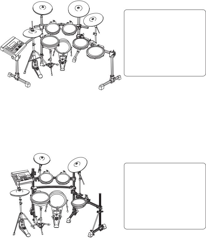
 DTXTREME SPECIAL SET
|
PCY135 |
PCY155 |
|
|
|
|
|
PCY135 |
|
TP100 |
TP100 |
DTXTREME |
RHH135 |
|
CH750
TP120SD |
TP100 |
|
|
|
KP125 |
|
TP100 |
SS662 |
Foot Pedal |
HS740A |
|
DTXTREME (Trigger Module ( ))
HXR4LD (Rack System ( ))
DTT3KSP1 (Pads Set ( ))
PCY135 × 2pcs.PCY155 × 1pc.RHH135 × 1pc.
KP125 |
× 1pc. |
CH750 |
× 2pcs. (Cymbal Holder ( )) |
SS662 |
× 1pc. (Snare Stand ( )) |
Connecting Cable
Drum Key
DTT3KSP2 (Pads Set ( ))
TP120SD |
× 1pc. |
TP100 |
× 4pcs. |
CH755 |
× 1pc. (Cymbal Holder ( )) |
HS740A |
× 1pc. (HI-HAT Stand ( )) |
|
: It is not included in the DTT3KSP. |
HXR4LD |
: DTT3KSP |
|
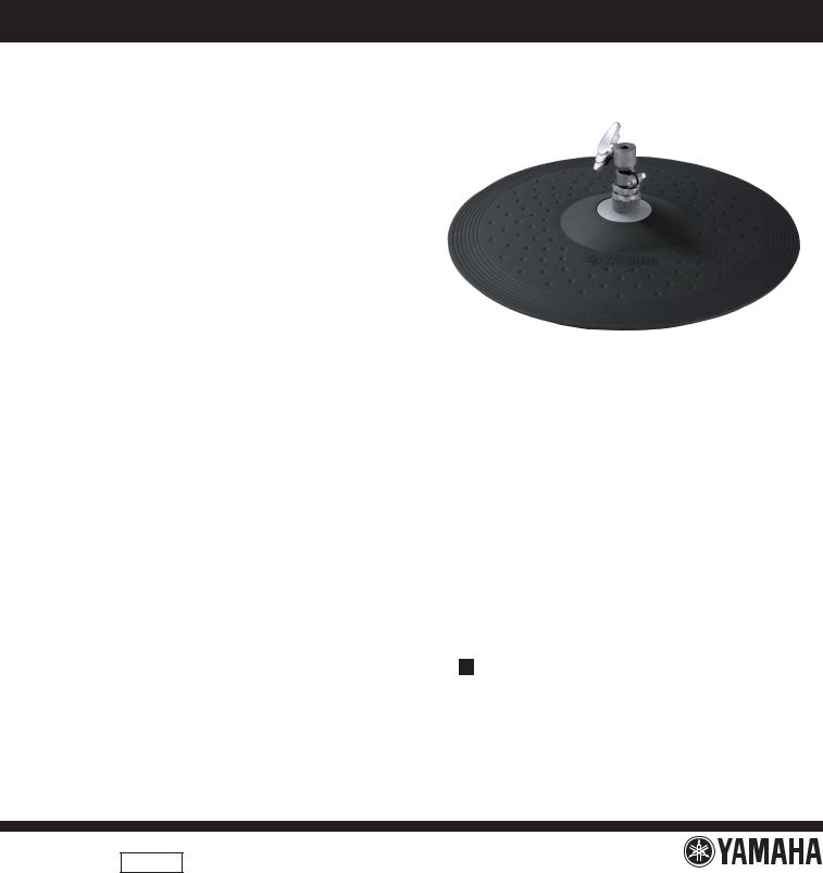
 DTXTREME STANDARD SET
|
|
|
|
|
DTXTREME (Trigger Module ( )) |
|
|
PCY135 |
|
|
|
RS130 (Rack System ( )) |
|
|
|
|
|
|
|
|
DTXTREME |
CH750 |
|
PCY155 |
|
DTT3KSTD1 (Pads Set ( )) |
|
|
|
|
|
|
PCY135 |
× 1pc. |
|
TP100 |
|
|
|
PCY155 |
× 1pc. |
|
TP100 |
|
|
RHH135 |
× 1pc. |
|
|
|
|
|
|||
|
|
|
CH755 |
|
KP125 |
× 1pc. |
|
|
|
|
CH750 |
× 1pc. (Cymbal Holder ( )) |
|
|
|
|
|
|
||
RHH135 |
|
|
|
|
SS662 |
× 1pc. (Snare Stand ( )) |
|
TP120SD |
|
|
|
Connecting Cable |
|
|
|
KP125 |
TP100 |
|
Drum Key |
|
HS650A |
|
|
|
|
DTT3KSTD2 (Pads Set ( )) |
|
|
|
|
|
|
||
|
|
|
|
|
TP120SD × 1pc. |
|
|
|
|
|
RS130 |
TP100 |
× 3pcs. |
|
SS662 |
|
|
CH755 |
× 1pc. (Cymbal Holder ( )) |
|
|
|
|
|
|
HS650A |
× 1pc. (HI-HAT Stand ( )) |
Foot Pedal
: It is not included in the DTT3KSTD.
: DTT3KSTD
2

DTT3KSP/DTT3KSTD
 COMPLETE ASSEMBLY
10 Complete Assembly 1 1
10f CH750
10a PCY135 |
10b PCY155 |
10c |
RHH135 |
10d |
KP125 |
10e SS662 |
DTT3KSP1: |
2pcs. |
DTT3KSP1: |
2pcs. |
DTT3KSTD1: |
1pc. |
DTT3KSTD1: |
1pc. |
●Accessories Set |
|
|
|
|
|
|
|
|
PCY135/PCY155 |
|
|
RHH135 |
|
|
|
Stand Base Set |
|
1 Rot Hold Parts Set |
2 |
Clutch Set |
3 |
|||||
1b |
1c |
|
2a |
2d |
|
|
|
|
|
|
|
3a |
|
||||
1a |
|
|
2c |
2e |
13 |
|
3b |
|
|
|
2f |
2bb |
|
|
|
|
|
|
|
|
|
|
|
|
||
|
DTT3KSP1: 3pcs. |
|
|
|
|
|
|
|
|
|
2ba |
2b |
|
|
|
3c |
|
|
DTT3KSTD1: 2pcs. |
|
|
|
|
|||
|
|
|
|
|
|
|||
|
KP125 |
|
|
|
|
5 |
6 |
|
9 |
11 |
12 |
|
|
|
|||
|
|
|
|
|
|
|
|
9 |
6 |
|
|
|
|
|
|
|
|
4 |
|
7 |
|
8 |
|
|
|
|
|
||
|
|
|
|
|
10 Cable Set SP SP |
10 Cable Set STD STD |
||||||
(DTT3KSP1) |
|
|
|
(DTT3KSTD1) |
|
|
|
10a 10b 10c 10g 10i |
10j |
10k |
10d 10e 10f 10h |
10a 10b 10c 10g 10i |
10j |
10k |
10d 10f |
2.5 m Stereo Phone Cable 4.0 m Stereo Phone Cable |
2.5 m Stereo Phone Cable 4.0 m Stereo Phone Cable |
|
2.5m 4.0m |
2.5m 4.0m |
|
|
|
|
● Spiral Tube
20 Complete Assembly 2 2
20a TP100 |
20b TP120SD |
20c HS740A |
20c HS650A |
20d CH755 |
|
|
(DTT3KSP only) |
(DTT3KSTD only) |
|
DTT3KSP2: 4pcs.DTT3KSTD2: 3pcs.
3

DTT3KSP/DTT3KSTD
 PARTS LIST
|
REF NO. |
PART NO. |
DESCRIPTION |
|
|
|
|
|
|
|
REMARKS |
QTY |
RANK |
|
|
|
|
COMPLETE ASSEMBLY |
|
|
|
|
|
|
|
DTT3KSP/DTT3KSTD |
|
|
|
|
10 |
-- |
COMPLETE ASSEMBLY 1 |
|
|
|
|
DTT3KSP |
(WM92480) |
|
|
|||
|
10 |
-- |
COMPLETE ASSEMBLY 1 |
|
|
|
|
DTT3KSP O 1 |
(WM92500) |
|
|
|||
|
10 |
-- |
COMPLETE ASSEMBLY 1 |
|
|
|
|
DTT3KSTD |
(WM92520) |
|
|
|||
|
10 |
-- |
COMPLETE ASSEMBLY 1 |
|
|
|
|
DTT3KSTD O 1 |
(WM92540) |
|
|
|||
|
10a |
-- |
OVERALL ASSEMBLY |
|
|
|
|
|
|
|
DTT3KSP PCY135 |
(WK36820) |
2 |
|
|
10a |
-- |
OVERALL ASSEMBLY |
|
|
|
|
|
|
|
DTT3KSTD PCY135 (WK36820) |
|
|
|
|
10b |
-- |
OVERALL ASSEMBLY |
|
|
|
|
|
|
|
PCY155 |
(WK72280) |
|
|
|
10c |
-- |
OVERALL ASSEMBLY |
|
|
|
|
|
|
|
RHH135 |
(WK37510) |
|
|
|
10d |
-- |
OVERALL ASSEMBLY |
|
|
|
|
|
|
|
KP125 |
(WK74870) |
|
|
* |
10e |
AAE96880 |
SNARE STAND |
|
|
SS662 |
|
|
|
|||||
* |
10f |
AAE96890 |
CYMBAL HOLDER |
|
|
DTT3KSP CH750 |
|
2 |
|
|||||
* |
10f |
AAE96890 |
CYMBAL HOLDER |
|
|
DTT3KSTD CH750 |
|
|
|
|||||
|
|
|
ACCESSORIES SET |
|
|
|
|
|
|
|
|
|
|
|
|
1 |
WK371500 |
ROT HOLD PARTS SET |
|
|
|
DTT3KSP PCY135/PCY155 |
3 |
|
|||||
|
1 |
WK371500 |
ROT HOLD PARTS SET |
|
|
|
DTT3KSTD PCY135/PCY155 |
2 |
|
|||||
|
1a |
-- |
ROTATION HOLD PART |
|
|
|
|
|
|
|
DTT3KSP PCY135/PCY155 |
3 |
|
|
|
|
|
|
|
|
|
|
|
|
|
|
(V857830) |
|
|
|
1a |
-- |
ROTATION HOLD PART |
|
|
|
|
|
|
|
DTT3KSTD PCY135/PCY155 |
2 |
|
|
|
|
|
|
|
|
|
|
|
|
|
|
(V857830) |
|
|
|
1b |
WM942400 |
BOLT |
6.0X10 DRUM KEY |
|
DTT3KSP PCY135/PCY155 |
3 |
|
||||||
|
1b |
WM942400 |
BOLT |
6.0X10 DRUM KEY |
|
DTT3KSTD PCY135/PCY155 |
2 |
|
||||||
|
1c |
WM813000 |
FELT WASHER |
D55X18T |
|
DTT3KSP PCY135/PCY155 |
3 |
|
||||||
|
1c |
WM813000 |
FELT WASHER |
D55X18T |
|
DTT3KSTD PCY135/PCY155 |
2 |
|
||||||
|
2 |
WK739000 |
CLUTCH SET |
|
|
RHH135 |
|
|
|
|||||
|
2a |
-- |
CLUTCH HEAD |
|
|
RHH135 |
(WK37630) |
|
|
|||||
|
2b |
WK734800 |
ROT HOLD PARTS ASSEMBLY |
|
|
RHH135 |
|
|
|
|||||
|
2ba |
-- |
ROT HOLD PARTS WELD |
|
|
RHH135 |
(WK73470) |
|
|
|||||
|
2bb |
WK738400 |
STOPPER CAP S BLACK |
|
|
RHH135 |
|
|
|
|||||
|
2c |
WK377200 |
NUT |
|
|
|
|
|
|
|
RHH135 |
|
2 |
|
|
2d |
WN784000 |
WING BOLT |
M6X9 |
|
|
RHH135 |
|
|
|
||||
* |
2e |
WN811400 |
DRUM KEY BOLT |
M6X12 |
|
|
RHH135 |
|
|
|
||||
|
2f |
WK378200 |
FELT WASHER |
|
|
RHH135 |
|
2 |
|
|||||
|
3 |
WK378800 |
STAND BASE SET |
|
|
RHH135 |
|
|
|
|||||
|
3a |
-- |
STAND BASE |
|
|
RHH135 |
(WK37840) |
|
|
|||||
|
3b |
-- |
SLIP SHEET BLACK |
|
|
RHH135 |
(WK37850) |
|
|
|||||
|
3c |
-- |
CUSHION BLACK |
|
|
|
|
|
|
|
RHH135 |
(WK40060) |
|
|
* |
4 |
WM027200 |
SPUR SPRING |
|
|
KP125 |
|
2 |
|
|||||
|
5 |
16033101 |
FP.HS STOPPER 2 |
|
|
KP125 |
|
2 |
04 |
|||||
|
6 |
WM795100 |
WING BOLT L |
|
|
KP125 |
|
2 |
|
|||||
|
7 |
WM795300 |
BD LEG R |
RIGHT |
|
KP125 |
|
|
|
|||||
|
8 |
WM795400 |
BD LEG L |
LEFT |
|
KP125 |
|
|
|
|||||
* |
9 |
WN553900 |
WASHER PLAIN |
8.0X16X1.0 MFZN2W3 |
|
|
|
|
|
|
KP125 |
|
2 |
|
|
10 |
-- |
CABLE SET SP |
|
|
DTT3KSP |
(WM79550) |
|
|
|||||
|
10 |
-- |
CABLE SET STD |
|
|
DTT3KSTD |
(WM79560) |
|
|
|||||
* |
10a |
WN547000 |
SNARE CABLE |
2.5 m STEREO PHONE |
|
|
|
|
|
|||||
* |
10b |
WN547200 |
TOM1 CABLE |
2.5 m STEREO PHONE |
|
|
|
|
|
|||||
* |
10c |
WN547300 |
TOM2 CABLE |
2.5 m STEREO PHONE |
|
|
|
|
|
|||||
* |
10d |
WN547400 |
TOM3 CABLE |
4.0 m STEREO PHONE |
|
|
|
|
|
|||||
* |
10e |
WN547500 |
TOM4 CABLE |
4.0 m STEREO PHONE |
|
DTT3KSP |
|
|
|
|||||
* |
10f |
WN547600 |
RIDE CABLE |
4.0 m STEREO PHONE |
|
|
|
|
|
|||||
* |
10g |
WN547700 |
CRASH1 CABLE |
2.5 m STEREO PHONE |
|
|
|
|
|
|||||
* |
10h |
WN547800 |
CRASH2 CABLE |
4.0 m STEREO PHONE |
|
DTT3KSP |
|
|
|
|||||
* |
10i |
WN547900 |
HI HAT CABLE |
2.5 m STEREO PHONE |
|
|
|
|
|
|||||
* |
10j |
WN548000 |
HH CON CABLE |
2.5 m STEREO PHONE |
|
|
|
|
|
|||||
* |
10k |
WN548100 |
KICK CABLE |
2.5 m STEREO PHONE |
|
|
|
|
|
|||||
* |
11 |
WM962100 |
DRUM KEY 3 |
|
|
|
|
|
|
|
|
|
|
|
|
12 |
V8234200 |
CABLE BAND |
|
|
|
|
|
10 |
99 |
||||
|
13 |
V8234200 |
CABLE BAND |
|
|
|
RHH135 |
|
|
99 |
||||
|
|
-- |
SPIRAL TUBE |
2.0 m |
|
|
|
|
|
|
||||
|
20 |
-- |
COMPLETE ASSEMBLY 2 |
|
|
|
DTT3KSP |
(WM92490) |
|
|
||||
|
20 |
-- |
COMPLETE ASSEMBLY 2 |
|
|
|
DTT3KSP O |
(WM92510) |
|
|
||||
|
20 |
-- |
COMPLETE ASSEMBLY 2 |
|
|
|
DTT3KSTD |
(WM92530) |
|
|
||||
|
20 |
-- |
COMPLETE ASSEMBLY 2 |
|
|
|
DTT3KSTD O |
(WM92550) |
|
|
||||
|
20a |
-- |
OVERALL ASSEMBLY |
|
|
|
|
|
|
|
DTT3KSP TP100 |
(WB96710) |
4 |
|
|
20a |
-- |
OVERALL ASSEMBLY |
|
|
|
|
|
|
|
DTT3KSP TP100 O |
(WK88890) |
4 |
|
|
20a |
-- |
OVERALL ASSEMBLY |
|
|
|
|
|
|
|
DTT3KSTD TP100 |
(WB96710) |
3 |
|
|
20a |
-- |
OVERALL ASSEMBLY |
|
|
|
|
|
|
|
DTT3KSTD TP100 O (WK88890) |
3 |
|
|
|
*: New Parts |
|
|
|
|
|
|
|
|
|
RANK: Japan only |
|||
4

DTT3KSP/DTT3KSTD
|
REF NO. |
PART NO. |
DESCRIPTION |
|
|
|
REMARKS |
QTY |
RANK |
||
|
20b |
-- |
OVERALL ASSEMBLY |
|
|
|
|
TP120SD |
(WB97090) |
|
|
|
20b |
-- |
OVERALL ASSEMBLY |
|
|
|
|
TP120SD O |
(WK88910) |
|
|
* |
20c |
AAE96790 |
HI-HAT STAND |
|
|
DTT3KSP HS740A |
|
|
|
||
* |
20c |
AAE96800 |
HI-HAT STAND |
|
|
DTT3KSTD HS650A |
|
|
|
||
* |
20d |
AAE96900 |
CYMBAL HOLDER |
|
|
CH755 |
|
|
|
||
|
|
|
|
|
|
|
|
|
|
|
|
*: New Parts |
RANK: Japan only |
1: “Environmental protection period mark label (WK53580)” and “Manufacture year/month label (WK75290)” are attached to the Pad of the destination “O” (for Chinese market).
1: O ( ) PAD “ (WK53580)” “ (WK75290)”
5
REAL HI-HAT PAD
RHH135
SERVICE MANUAL
ED 011895
20080401-27300
CONTENTS |
|
SPECIFICATIONS ...................................... |
2 |
DISASSEMBLY PROCEDURE ................... |
3 |
CIRCUIT BOARDS .............................. |
7 |
CIRCUIT DIAGRAM ....................................... |
7 |
OUTPUT CHECK ....................................... |
8 |
PARTS LIST |
|
HAMAMATSU, JAPAN
Copyright (c)Yamaha Corporation. All rights reserved. PDF 
 ’08.03

RHH135
IMPORTANT NOTICE
This manual has been provided for the use of authorized Yamaha Retailers and their service personnel. It has been assumed that basic service procedures inherent to the industry, and more specifically Yamaha Products, are already known and understood by the users, and have therefore not been restated.
WARNING :
IMPORTANT :
Failure to follow appropriate service and safety procedures when servicing this product may result in personal injury, destruction of expensive components and failure of the product to perform as specified. For these reasons, we advise
all Yamaha product owners that all service required should be performed by an authorized Yamaha Retailer or the appointed service representative.
This presentation or sale of this manual to any individual or firm does not constitute authorization certification, recognition of any applicable technical capabilities, or establish a principal-agent relationship of any form.
The data provided is belived to be accurate and applicable to the unit(s) indicated on the cover. The research engineering, and service departments of Yamaha are continually striving to improve Yamaha products. Modifications are, therefore, inevitable and changes in specification are subject to change without notice or obligation to retrofit. Should any discrepancy appear to exist, please contact the distributor’s Service Division.
WARNING :
IMPORTANT :
Static discharges can destroy expensive components. Discharge any static electricity your body may have accumulated by grounding yourself to the ground bus in the unit (heavy gauge black wires connect to this bus.)
Turn the unit OFF during disassembly and parts replacement. Recheck all work before you apply power to the unit.
WARNING: This product contains chemicals known to the State of California to cause cancer, or birth defects or other reproductive harm.
DO NOT PLACE SOLDER, ELECTRICAL/ELECTRONIC OR PLASTIC COMPONENTS IN YOUR MOUTH FOR ANY REASON WHAT SO EVER!
Avoid prolonged, unprotected contact between solder and your skin! When soldering, do not inhale solder fumes or expose eyes to solder/ flux vapor!
If you come in contact with solder or components located inside the enclosure of this product, wash your hands before handling food.
 WARNING
Components having special characteristics are marked  and must be replaced with parts having specification equal to those originally installed.

 SPECIFICATIONS
Size |
ø329 x 61 (H) mm |
|
(hi-hat clutch not included) |
||
|
||
|
|
|
Weight |
1.4 kg (hi-hat clutch included) |
|
|
|
|
Sensor System |
Trigger sensor (piezo) x 1, |
|
switch x 1 (edge) |
||
|
||
|
|
|
Controller Type |
Multi-step Switch |
|
|
|
|
Output jack |
Standard stereo phone jack x 2 |
|
|
|
|
|
φ329 X 61 (H) mm |
|
|
|
|
|
|
|
|
|
|
|
1.4 kg |
|
|
x 1 |
|
x 1 |
|
|
|
|
|
|
|
|
|
|
|
|
|
|
|
x 2 |
|
|
|
2
RHH135
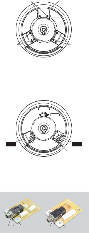
 DISASSEMBLY PROCEDURE
1.JK1 Circuit Board, JK2 Circuit Board
(Time required: About 1 minute)
1-1 Remove the following screws and remove the rear cover. (Fig. 1)
[100]: 6 pcs.
1.JK1 JK2 1
1-1 1
[100]: 6
<Bottom view >
[100] Rear cover
[100] |
[100] |
1-2 Remove the following screw and remove the JK1 circuit board. (Fig. 2)
[110A]: 1 pc.
*The jack holder is not part of the JK1 circuit board. When replacing the JK1 circuit board, remove the nut marked [A] and washer marked
[C]to remove the jack holder, and install it on the new JK1 circuit board. (Photo 1)
[100]: PW Head Tapping Screw-B B PWH
3.0X12 MFZN2B3 (WM788200)
Fig.1 1
<Bottom view >
1-3 Remove the following screw and remove the JK2 circuit board. (Fig. 2)
[110B]: 1 pc.
*The jack holder is not part of the JK2 circuit board. When replacing the JK2 circuit board, remove the nut marked [B] and washer marked
[D]to remove the jack holder, and install it on the new JK2 circuit board. (Photo 1)
1-2 JK1 2
[110A]:1
JK1JK1 [A]1 [C] 1 JK11
1-3 JK2 2
[110B]:1
JK2JK2 [B]
1 [D] 1 JK2
1
JK2 |
JK1 |
[110B] |
[110A] |
[110]: Bind Head Tapping Screw-B B BIND
3.0X8 MFZN2W3 (WE774300)
Fig.2 2
JK1 |
|
JK2 |
Jack holder |
Jack holder |
[A] [C] [B] [D] |
|
|
|
Photo 1 1 |
|
3
RHH135
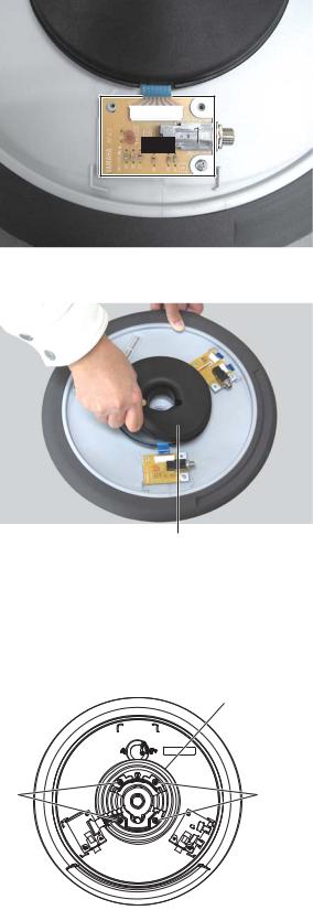
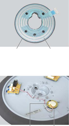
2.RHH Sheet Switch
(Time required: About 2 minutes)
2-1 Remove the rear cover. (See procedure 1-1)
2-2 Disconnect the connector of the JK2 circuit board. (Photo 2)
2.RHH 2
2-1 1-1
2-2 JK2 2
CN5 |
JK2 |
2-3 Remove the RHH actuator. (Photo 3)
2-3 RHH 3
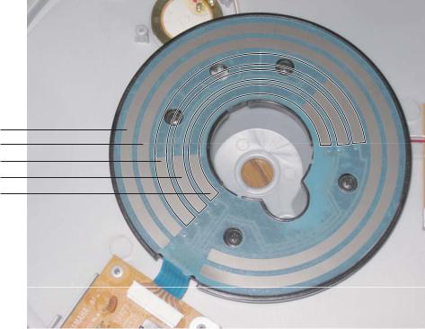
2-4 Remove the following screws and remove the sensor board. (Fig. 3)
[120]: 4 pcs.
2-4
3
[120]: 4
Photo 2 2
RHH actuatorRHH
Photo 3 3
*The appearance of the JK1 circuit board is slightly different from that in the picture.
JK1
<Bottom view >
Sensor board
[120] |
[120] |
[120]: PW Head Tapping Screw-B B PWH
3.0X12 MFZN2B3 (WM788200)
Fig.3 3
4
RHH135
2-5 Remove the RHH sheet switch from the sensor board. (Photo 4)
2-5 RHH4
3.Sensor Unit
(Time required: About 3 minutes)
3-1 Remove the rear cover. (See procedure 1-1) 3-2 Remove the sensor board. (See procedure 2-4) 3-3 Remove the sensor unit. (Photo 5)
*The sensor unit is secured with the sensor tape.
*After installing the sensor unit, press it lightly to make sure that it is secured with the sensor tape firmly.
3.3
3-1 1-1 3-2 2-4 3-3 5
Sensor board |
RHH sheet switch |
|
RHH |
Photo 4 4
Sensor unit |
Sensor tape |
|
|
Photo 5 5
*The appearance of the JK1 circuit board is slightly different from that in the picture.
JK1
5
RHH135
4.RIM Sheet Switch F, RIM Sheet Switch R
(Time required: About 3 minutes)
4-1 |
Remove the rear cover. (See procedure 1-1) |
|
|
4-2 |
Disconnect the connector of the JK1 circuit board. |
|
|
|
(Photo 6) |
JK1 |
|
|
RIM Sheet Switch F: CN2 |
|
|
|
RIM Sheet Switch R: CN4 |
CN4 |
CN2 |
3
4-1 1-1
4-2 JK1 6
: CN2: CN4
Photo 6 6
*The appearance of the JK1 circuit board is slightly different from that in the picture.
JK1
4-3 Remove the rubber pad by stretching edge portion of the rubber pad with fingers. (Photo 7)
*When installing the rubber pad, be sure to replace the pad tape 13F (WK370400) and pad tape 13R (WK370500) with new ones. (Photo 8)
4-3 7
13F (WK370400) 13R (WK370500)
8
Rubber pad
Photo 7 7
* The appearance of the JK1 circuit board is slightly different
|
from that in the picture. |
||
|
JK1 |
||
4-4 Remove the RIM sheet switch F and RIM sheet |
RIM sheet switch R |
||
|
|||
switch R. (Photo 8) |
|||
Pad tape R |
|
||
|
|
||
|
13R |
||
4-4 |
|
|
|
8 |
|
|
|
Pad tape F13F
RIM sheet switch F
Photo 8 8
6
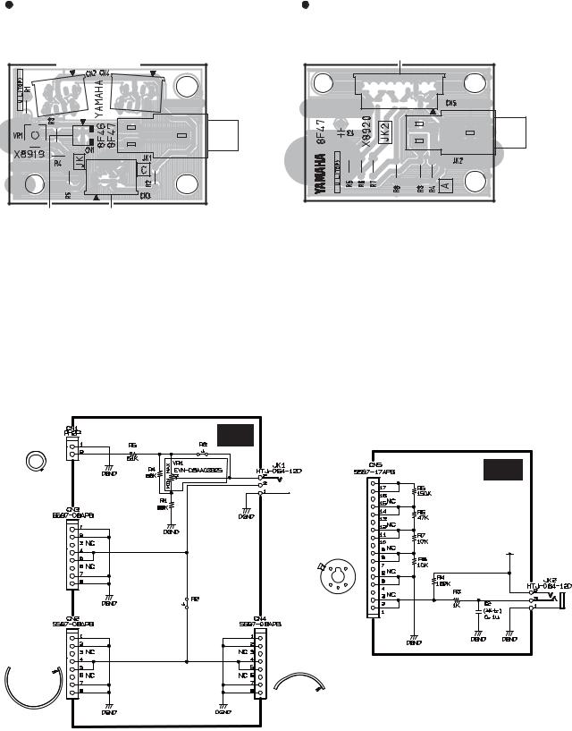
 CIRCUIT BOARDS
JK1 Circuit Board |
|
JK2 Circuit Board |
|||||||||||||||||||||||||||||||||||||||||||||||||||||||||||||||||||||||||||||||
to RIM sheet switch F |
|
|
|
|
|
|
|
|
|
|
|
|
|
|
|
|
|
|
|
|
|
|
|
|
|
|
|
|
|
|
|
|
|
|
|
|
|
||||||||||||||||||||||||||||||||||||||||||||
|
|
|
|
|
|
|
|
|
|
|
|
|
|
|
|
|
to RIM sheet switch R |
|
|
|
|
|
|
|
|
|
to RHH sheet switch |
||||||||||||||||||||||||||||||||||||||||||||||||||||||
|
|
|
|
|
|
|
|
|
|
|
|
|
|
|
|
|
|
|
|
|
|
|
|
|
|
|
|
|
|
|
|
|
|
|
|
|
|
|
|
|
|
|
|
|
|
|
|
|
|
|
|
|
|
|
|
|
|
|
|
|
|
|
|
|
|
|
|
|
|
|
|
|
|
|
|
|
|
|
|
|
|
|
|
|
|
|
|
|
|
|
|
|
|
|
|
|
|
|
|
|
|
|
|
|
|
|
|
|
|
|
|
|
|
|
|
|
|
|
|
|
|
|
|
|
|
|
|
|
|
|
|
|
|
|
|
|
|
|
|
|
|
|
|
|
|
|
|
|
|
|
|
|
|
|
|
|
|
|
|
|
|
|
|
|
|
|
|
|
|
|
|
|
|
|
|
|
|
|
|
|
|
|
|
|
|
|
|
|
|
|
|
|
|
|
|
|
|
|
|
|
|
|
|
|
|
|
|
|
|
|
|
|
|
|
|
|
|
|
|
|
|
|
|
|
|
|
|
|
|
|
|
|
|
|
|
|
|
|
|
|
|
|
|
|
|
|
|
|
|
|
|
|
|
|
|
|
|
|
|
|
|
|
|
|
|
|
|
|
|
|
|
|
|
|
|
|
|
|
|
|
|
|
|
|
|
|
|
|
|
|
|
|
|
|
|
|
|
|
|
|
|
|
|
|
|
|
|
|
|
|
|
|
|
|
|
|
|
|
|
|
|
|
|
|
|
|
|
PAD |
RHH135
HI-HAT CONTROL
to Sensor unit |
not installed |
Component side |
Component side |
 CIRCUIT DIAGRAM
to Sensor unit |
JK1 |
|
not installed
JK2

 PAD
PAD
|
to RHH sheet |
|
not installed |
switch |
1 |
|
|
HI-HAT
CONTROL
to RIM sheet |
to RIM sheet |
|
switch F |
||
switch R |
||
|
1 Voltage value differs depending on models. Refer to page 9.
1 9
7
RHH135
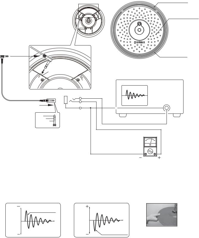
 OUTPUT CHECK
Preparations |
|
• Oscilloscope |
|
• Tester |
|
• Connect cable |
|
• Drum stick |
|
PAD output jack
(PAD )
PAD
[R]
Rim area ( )
Pad area ( )
[F]
Rim area ( )
Cymbal is fitted. ( )
|
|
Oscilloscope ( ) |
|
|
Check the pad. |
Stereo cable |
TIP |
( ) |
|
RING |
ch1 |
|
|
|
|
SLEEVE |
|
TIP |
|
|
RING |
|
|
SLEEVE |
|
|
* Take care to avoid damage while holding the product |
Check the rim switch. |
Tester (ohm meter) |
|
( ( )) |
|||
or by giving it a shock. |
( ) |
||
|
|
||
|
|
1. Checking Pad Area For Output |
1. |
Check for phase (polarity) by tapping the pad area. |
( ) |
(Check for the change in the crest value according to |
|
whether the output is high or low) |
|
2. Checking Rim Area for Output ([F] and [R]) |
2. [F] [R] |
Check that the tester (ohm meter) points to approxi- |
|
mately 10 Ω when the rim area is lightly picked up. |
10 Ω |
A Output V
V
|
OK |
1st wave 1 |
|
|
Time t |
|
t |
Probe 10 : 1 |
0.2 V/DIV, 5 mS |
NG
B Output V
V Time t
t
1st wave 1
0.2 V/DIV, 5 mS
ch1: Signal waveform of pad.
ch1
ch1: Signal waveform of pad.
ch1
Note: Be sure to tap the YAMAHA logo for checking waveform.
YAMAHA
8
RHH135
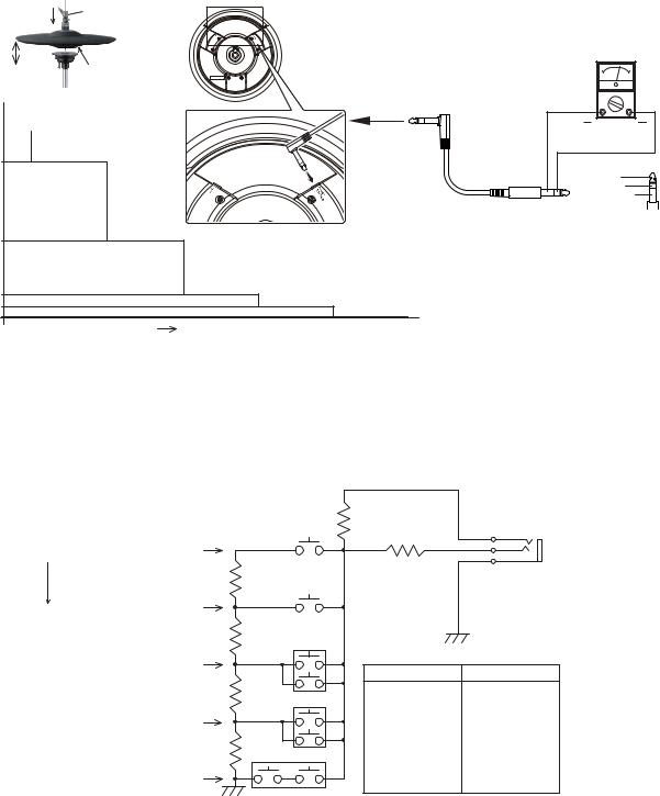
3. Checking HI-HAT Control
Pushing the clutch head downward turns on the switch.
The force (F) used then brings about the change in the ON atatus of the switches (A to E).
[Checking Single RHH135]
Connect the stereo phone cable to the HI-HAT Control terminal. Pusing the clutch head downward brings about a change in the resistance between RINGS and SLEEVE.
3.HI-HAT CONTROL
F ON A E
[RHH135 ]
HI-HAT CONTROLRINGSELEEVE
|
F |
Clutch head |
|
|
|
Switch: OFF |
|
|
|
|
|
Switch: ON |
|
Switch |
|
|
|
|
|
|
|
|
|
|
|
OPEN |
|
|
(Switch: OFF) |
|
|
HI-HAT |
|
|
CONTROL |
|
220 KΩ |
A: ON (207.1 – 228.9 KΩ) |
|
|
|
RESISTANCE |
|
HI-HAT CONTROL |
|
B: ON (64.6 – 71.4 KΩ) |
|
|
70 KΩ |
|
|
|
|
|
20 KΩ |
C: ON (19.95 – 22.05 KΩ) |
|
D: ON (10.45 – 11.55 KΩ) |
|
|
10 KΩ |
|
|
E: ON (0.95 – 1.05 KΩ) |
|
|
1 KΩ |
|
|
|
|
|
|
F |
Tester (ohm meter) |
|
TIP
RING
SLEEVE
(Reference)
[Checking by Connecting with Trigger Module]
Connecting with the trigger module supplies the voltage Vcc from the TIP, causing variations in the RING voltage according to the status of the switches A to E. In case of DTXTREME III, the following voltage value is as follows. (Voltage value differs depending on models.)
F A: ON |
2.32 – 2.86 V |
|
|
R5 |
150 K |
B: ON |
1.52 – 1.98 V |
|
TIP Vcc A E RINGDTXTREME III
Vcc=3.3 V or Vcc=5.0 V
|
R4 150 K |
HI-HAT |
|
A |
CONTROL |
||
|
R3 |
2 |
TIP |
|
|
3 |
RING |
|
|
1 |
SLEEVE |
|
1 K |
|
|
B |
|
|
|
|
|
R6 |
47 K |
C |
|
|
|
|
|
|
|
|
|
C: ON |
0.70 |
– 0.96 V |
|
|
Vcc=3.3 V |
Vcc=5.0 V |
|
|
|
|
|
||
|
|
R7 |
10 K |
D |
• DTXPRESS |
• DTXTREME |
|
|
• DTXPRESS II |
• DTXTREME IIS |
|||
|
|
|
|
|||
|
|
|
|
|
||
D: ON |
0.40 |
– 0.56 V |
|
|
• DTXPRESS III |
etc. |
|
|
|
|
|
• DTXPRESS IV |
|
|
|
R8 |
10 K |
E |
• DTXPLORER |
|
E: ON |
0 |
– 0.04 V |
|
|
• DTXTREME III |
|
|
|
etc. |
|
|||
|
|
|
|
|
|
9
RHH135
A
B
C
D
E
10

REAL HI-HAT PAD
RHH135
PARTS LIST |
|
CONTENTS |
|
OVERALL ASSEMBLY ............................................... |
2 |
ELECTRICAL PARTS ............................................. |
4 |
Notes : DESTINATION ABBREVIATIONS
A : |
Australian model |
M: |
South African model |
B : |
British model |
O : |
Chinese model |
C : |
Canadian model |
Q : |
South-east Asia model |
D : |
German model |
T : |
Taiwan model |
E : |
European model |
U : |
U.S.A. model |
F : |
French model |
V : General export model (110V) |
|
H : |
North European model |
W: General export model (220V) |
|
I : |
Indonesian model |
N,X: General export model |
|
J : |
Japanese model |
Y : |
Export model |
K : |
Korean model |
|
|
 WARNING
Components having special characteristics are marked |
and must be replaced with parts having |
specification equal to those originally installed. |
|

•The numbers “QTY” show quantities for each unit.
•The parts with “--” in “PART NO.” are not available as spare parts.
•This mark “ } ” in the REMARKS column means these parts are interchangeable.
•The second letter of the shaded (  ) part number is O, not zero.
•The second letter of the shaded (  ) part number is I, not one.
•QTY
•PART NO. “--”
•REMARKS }
•PART NO. 2
•PART NO. 2
 Loading...