


FT-857D
OPERATING MANUAL
VERTEX STANDARD CO., LTD.
4-8-8 Nakameguro, Meguro-Ku, Tokyo 153-8644, Japan
VERTEX STANDARD
US Headquarters
10900 Walker Street, Cypress, CA 90630, U.S.A.
International Division
8350 N.W. 52nd Terrace, Suite 201, Miami, FL 33166, U.S.A.
YAESU EUROPE B.V.
P.O. Box 75525, 1118 ZN Schiphol, The Netherlands
YAESU UK LTD.
Unit 12, Sun Valley Business Park, Winnall Close
Winchester, Hampshire, SO23 0LB, U.K.
VERTEX STANDARD HK LTD.
Unit 5, 20/F., Seaview Centre, 139-141 Hoi Bun Road,
Kwun Tong, Kowloon, Hong Kong

Contents
Introduction ..................................................................... 1
Specifications................................................................... 2
Accessories & Options ................................................... 4
Installation ....................................................................... 5
Preliminary Inspection ................................................. 5
Installation Tips ........................................................... 5
Safety Information ....................................................... 6
Installing the Microphone and Front Panel ................ 7
Power connections ....................................................... 8
Grounding .................................................................. 10
Mobile Station Grounding.................................... 10
Base Station Earth Grounding.............................. 11
Antenna Considerations ............................................ 12
Mobile Antenna Installations ............................... 12
Base Station Antenna Installations ...................... 13
RF Field Exposure ..................................................... 14
Electromagnetic Compatibility.................................. 15
Heat and Ventilation .................................................. 15
Linear Amplifier Interfacing...................................... 16
CW Key/Keyer Connections ..................................... 17
Receiver Accessories (Tape Recorder etc.) ............. 18
Adjusting the Front Feet ............................................ 18
Front Panel Control & Switches................................. 20
Multi Function Key Detail......................................... 24
Rear panel Connectors ................................................ 32
Operation ....................................................................... 34
Turning the Transceiver On and Off ......................... 34
Operating Band Selection.......................................... 34
Mode Selection .......................................................... 34
Adjusting the Audio Volume Level .......................... 35
Menu Quick Start ...................................................... 35
Adjusting the RF Gain and Squelch.......................... 36
Setting the Operating Frequency............................... 36
Changing the Dial Speed ........................................... 37
Stacked VFO System ................................................ 37
Receiver Accessories .................................................... 38
Locking Front Panel Controls ................................... 38
Clarifier ...................................................................... 39
IF Shift ....................................................................... 40
AGC ........................................................................... 41
Noise Blanker ............................................................ 41
IPO ............................................................................. 42
ATT (Front End Attenuator) ..................................... 42
DSP Bandpass Filter (DBP) ...................................... 43
DSP CW Peaking Filter (DBF) ................................. 44
DSP Noise Reduction (DNR) ................................... 44
DSP Notch Filter (DNF) ........................................... 45
AM/FM Tuning Dial Operation ................................ 45
Automatic Power-Off Feature ................................... 46
Transmitter Operation ................................................ 48
SSB/AM Transmission .............................................. 48
Basic Setup/Operation.......................................... 48
VOX Operation .................................................... 49
AF Speech Processor Operation .......................... 50
DSP Microphone Equalizer ................................. 51
CW Transmission ...................................................... 52
Operation using Straight Key/External Keying Device
Using the Built-in Electronic Keyer..................... 54
FM Transmission ....................................................... 56
Basic Setup/Operation.......................................... 56
Repeater Operation .............................................. 57
Tone Search Scanning .......................................... 58
.. 52
DCS Operation ..................................................... 59
DCS Search Scanning .......................................... 59
Split Tone Operation ............................................ 60
ARTSTM Operation ............................................... 61
CW Identifier Setup ........................................ 62
Digital Mode Operation (SSB-Based AFSK) .......... 63
RTTY (Radio Tele Type) Operation ................... 63
PSK31 Operation.................................................. 64
“User” Defined Digital Modes ............................ 64
Packet (1200/9600 bps FM) Operation .................... 65
WeatherFax Monitoring ............................................ 66
Time-Out Timer ......................................................... 67
Split Frequency Operation ........................................ 67
ATAS-100/-120 Operation ....................................... 68
Automatic Tuning ................................................. 68
Manual Tuning...................................................... 69
ATAS-100/-120 Operating Tips .......................... 70
FC-30 Automatic Antenna Tuner Operation ............ 71
Antenna Tuner Memory System .......................... 72
Memory Operation....................................................... 73
QMB (Quick Memory Bank) Channels ................... 73
Memory Operation on “Regular” Memory Channel
Normal Memory Storage ..................................... 74
Split-Frequency Memory Storage ........................ 75
Memory Channel Recall ...................................... 76
Masking (“Hiding”) a Memory............................ 77
Memory Operation on “HOME” Channel Memories
Labeling Memories after Programming Channel Data
Spectrum Scope Monitor ............................................. 80
Smart SearchTM............................................................ 81
Scanning Operation ...................................................... 82
Scanning Features ...................................................... 82
Scanning Operation ................................................... 82
Scan-Resume Choices .......................................... 83
Scan Skip Programming (Memory Mode only) .. 83
“Priority Channel” Scanning ..................................... 85
Programmable Memory Scan (PMS) Operation ...... 86
Dual Watch Operation............................................... 87
Miscellaneous Settings ................................................. 88
Operation on Alaska Emergency Frequency: 5167.5 kHz
CW Training Feature ................................................. 89
Programming the Panel Key Functions..................... 89
Beacon Feature .......................................................... 90
Beacon Text Storage ............................................ 90
Beacon Text Sending (On the Air) ...................... 91
Display Customization .............................................. 92
Display Lamp Mode ............................................. 92
Display Contrast ................................................... 92
Display Dimmer ................................................... 92
Display Color ....................................................... 93
Menu Operation ........................................................... 94
CAT (Computer Aided Transceiver) Operation . 113
Power-On Microprocessor Reset Procedures ........ 117
Cloning ......................................................................... 118
Installation Optional Accessories ............................. 119
Optional Digital Signal Processing Unit DSP-2
Optional Filters:YF-122S, YF-122C, and YF-122CN
Optional High Stability Reference Oscillator TCXO-9
Appendix ...................................................................... 122
Setup of Memories
for Low Earth Orbit (LEO) FM Satellite Operation
MH-59A8J Remote Microphone .............................. 125
........ 74
....... 78
..... 79
... 88
............ 119
.... 120
.. 121
....... 122

INTRODUCTION
HOME
CLAR
L
Q
A
S
F
F
R
/
E
C
L
E
T
S
FUNC
The FT-857 is a rugged, innovative multiband, multimode mobile/portable transceiver for
the amateur radio MF/HF/VHF/UHF bands. Providing coverage of the 160-10 meter bands
plus the 6 m, 2 m, and 70 cm bands, the FT-857 includes operation on the SSB, CW, AM,
FM, and Digital modes, yielding the most comprehensive performance package available
for mobile and field operation.
Engineered for high performance, the FT-857 provides 100 watts power output on the 160
through 6 meter bands, 50 watts power output on 2 meters, and 20 watts output on 70 centimeters.
The multi-function Liquid-Crystal Display includes attractive backlighting (32 colors available!). The display includes bar-graph indication of power output, ALC voltage, SWR, modulation level, and/or signal strength. Also included are a number of operating status icons, as
well as the function displays for the three operating function keys ([A], [B], and [C]).
Among the advanced features of the FT-857 are many incorporated only in large basestation transceivers. These include Dual VFOs; Split-Frequency operation; Digital Signal
Processing (Bandpass Filtering, Noise Reduction, Auto-Notch, and Microphone Equalizer);
IF Shift; Clarifier (“R.I.T.”); IF Noise Blanker; AGC Fast/Slow/Auto/Off selection; RF Gain
and Squelch control; IPO (Intercept Point Optimization) and a receiver front-end Attenuator; AM Aircraft reception; AM and FM Broadcast reception; U.S. Weather Band reception;
VOX; Built-in Electronic Keyer with Memories and a Beacon mode; Adjustable CW Pitch;
Automatic FM Repeater Shift (ARS); Built-in CTCSS Encoder/Decoders; ARTS™ (AutoRange Transponder System); Smart Search™ Automatic Memory Loading System; Spectrum Scope; 200 Memories plus Home Channels and Band-limiting Memories; Alpha-Numeric Labeling of Memories; Automatic Power-Off (APO) and Time-Out Timer (TOT) functions; Computer Interface capability; and Cloning capability.
We urge you to read this manual in its entirety, so as to gain a full understanding of the
amazing capability of the exciting new FT-857 Transceiver.
1FT-857 Operating Manual

SPECIFICATIONS
General
Frequency Range: Receive: 0.1-56 MHz, 76-108 MHz, 118-164 MHz,
420-470 MHz
Transmit: 160 - 6 Meters, 2 Meters,
70 Centimeters (Amateur bands only)
Emission Modes: A1 (CW), A3 (AM), A3J (LSB/USB), F3 (FM),
F1 (9600 bps packet), F2 (1200 bps packet)
Synthesizer Steps (Min.): 10 Hz (CW/SSB), 100 Hz (AM/FM/WFM)
Antenna Impedance: 50 Ohms, Unbalanced
Operating Temp. Range: 14 ºF to 140 ºF (–10 °C to +60 °C)
Frequency Stability: ±4 ppm from 1 min. to 60 min after power on.
@25 °C: 1 ppm/hour
±0.5 ppm/1 hour @25 °C, after warmup
(with optional TCXO-9)
Supply Voltage: Normal: 13.8 VDC ±15 %, Negative Ground
Current Consumption: Squelched: 550 mA (Approx.)
Receive: 1 A
Transmit: 22 A
Case Size (W x H x D): 6.1” x 2.0” x 9.2” (155 x 52 x 233 mm)
Weight (Approx.): 4.6 lb. (2.1 kg)
Transmitter
RF Power Output: SSB/CW/FM AM Carrier
(@13.8 V DC) 160- 6 M: 100 W 25 W
2 M: 50 W 12.5 W
70 CM: 20 W 5 W
Modulation Types: SSB: Balanced Modulator,
AM: Early Stage (Low Level),
FM: Variable Reactance
FM Maximum Deviation: ±5 kHz (FM-N: ±2.5 kHz)
Spurious Radiation: –50 dB (1.8-29.7 MHz)
–60 dB (50/144/430 MHz)
Carrier Suppression: >40 dB
Opp. Sideband Suppression: >50 dB
SSB Frequency Response: 400 Hz-2600 Hz (–6 dB)
Microphone Impedance: 200-10k Ohms (Nominal: 600 Ohms)
2 FT-857 Operating Manual

SPECIFICATIONS
Receiver
Circuit Type: Double-Conversion Superheterodyne (SSB/CW/AM/FM)
Superheterodyne (WFM)
Intermediate Frequencies: 1st: 68.33 MHz (SSB/CW/AM/FM); 10.7 MHz (WFM)
2nd: 455 kHz
Sensitivity: SSB/CW AM FM
100 kHz-1.8 MHz – 32 µV –
1.8 MHz-28 MHz 0.2 µV 2 µV –
28 MHz-30 MHz 0.2 µV 2 µV 0.5 µV
50 MHz-54 MHz 0.125 µV 1 µV 0.2 µV
144/430 MHz 0.125 µV – 0.2 µV
(SSB/CW/AM = 10 dB S/N, FM = 12 dB SINAD)
Squelch Sensitivity: SSB/CW/AM FM
100 kHz-1.8 MHz – –
1.8 MHz-28 MHz 2.5 µV –
28 MHz-30 MHz 2.5 µV 0.32 µV
50 MHz-54 MHz 1 µV 0.16 µV
144/430 MHz 0.5 µV 0.16 µV
Image Rejection: HF/50 MHz: 70 dB,
144/430 MHz: 60 dB
IF Rejection: 60 dB
Selectivity (–6/–60 dB): SSB/CW: 2.2 kHz/4.5 kHz
AM: 6 kHz/20 kHz
FM: 15 kHz/30 kHz
FM-N: 9 kHz/25 kHz
SSB (optional YF-122S installed): 2.3 kHz/4.7 kHz (–66 dB)
CW (option YF-122C installed): 500 Hz/2.0 kHz
CW (option YF-122CN installed): 300 Hz/1.0 kHz
AF Output: 2.5 W (@4 Ohms, 10% THD or less)
AF Output Impedance: 4-16 Ohms
Specifications are subject to change without notice, and are guaranteed within the amateur
bands only.
3FT-857 Operating Manual

ACCESSORIES & OPTIONS
SUPPLIED ACCESSORIES
Hand Microphone MH-31A8J ............................................................................................... 1
Mobile Mounting Bracket MMB-82.................................................................................... 1
DC Power Cord..................................................................................................................... 1
Operating Manual ................................................................................................................. 1
Warranty Card ....................................................................................................................... 1
AVAILABLE OPTIONS
FP-1030A External AC Power Supply (25A)
DSP-2 Digital Signal Processing Unit
YF-122S Collins SSB Filter (2.3 kHz/4.7 kHz: –6 dB/–66 dB)
YF-122C Collins CW Filter (500 Hz/2 kHz: –6 dB/–60 dB)
YF-122CN Collins CW Filter (300 Hz/1 kHz: –6 dB/–60 dB)
TCXO-9 TCXO Unit (±0.5 ppm)
MD-200A8X Desktop Microphone
MH-36E8J DTMF Microphone
MH-59A8J Remote Control Microphone
YSK-857 Separation Kit
FC-30 External Automatic Antenna Tuner
ATAS-100 Active-Tuning Antenna System
ATAS-120 Active-Tuning Antenna System
ATBK-100 VHF/UHF Antenna Base/Counterpoise Kit
VL-1000 Solid-State Linear Amplifier
CT-62 CAT Interface Cable
CT-39A Packet Cable
CT-58 BAND DATA Cable
4 FT-857 Operating Manual

INSTALLATION
This chapter describes the installation procedure for integrating the FT-857 into a typical
amateur radio station. It is presumed that you possess technical knowledge and conceptual
understanding consistent with your status as a licensed radio amateur. Please take some
extra time to make certain that the important safety and technical requirements detailed in
this chapter are followed closely.
PRELIMINARY INSPECTION
Inspect the transceiver visually immediately upon opening the packing carton. Confirm that
all controls and switches work freely, and inspect the cabinet for any damage. Gently shake
the transceiver to verify that no internal components have been shaken loose due to rough
handling during shipping.
If any evidence of damage is discovered, document it thoroughly and contact the shipping
company (or your local dealer, if the unit was purchased over-the-counter) so as to get
instructions regarding the prompt resolution of the damage situation. Be certain to save the
shipping carton, especially if there are any punctures or other evidence of damage incurred
during shipping; if it is necessary to return the unit for service or replacement, use the original packing materials but put the entire package inside another packing carton, so as to
preserve the evidence of shipping damage for insurance purposes.
INSTALLATION TIPS
To ensure long life of the components, be certain to provide adequate ventilation around the
cabinet of the FT-857.
Do not install the transceiver on top of another heat-generating device (such as a power
supply or amplifier), and do not place equipment, books, or papers on top of the FT-857.
Avoid heating vents and window locations that could expose the transceiver to excessive
direct sunlight, especially in hot climates. The FT-857 should not be used in an environment
where the ambient temperature exceeds 140º F (+60 °C).
5FT-857 Operating Manual
INSTALLATION
SAFETY INFORMATION
The FT-857 is an electrical apparatus, as well as a generator of RF (Radio Frequency)
energy, and you should exercise all safety precautions as are appropriate for this type of
device. These safety tips apply to any device installed in a well-designed amateur radio
station.
Never allow unsupervised children to play in the vicinity of your transceiver or antenna installation.
Be certain to wrap any wire or cable splices thoroughly with insulating electrical
tape, to prevent short circuits.
Do not route cables or wires through door jambs or other locations where, through
wear and tear, they may become frayed and shorted to ground or to each other.
Do not stand in front of a directional antenna while you are transmitting into that
antenna. Do not install a directional antenna in any location where humans or pets
may be walking in the main directional lobe of the antenna’s radiation pattern.
In mobile installations, it is preferable to mount your antenna on top of the roof of the
vehicle, if feasible, so as to utilize the car body as a counterpoise for the antenna and
raise the radiation pattern as far away from passengers as possible.
During vehicular operation when stopped (in a parking lot, for example), make it a
practice to switch to Low power if there are people walking nearby.
Never wear dual-earmuff headphones while driving a vehicle.
Do not attempt to drive your vehicle while making a telephone call on an autopatch
using the DTMF microphone. Pull over to the side of the road, whether dialing manu-
ally.
6 FT-857 Operating Manual
INSTALLATION
BAND
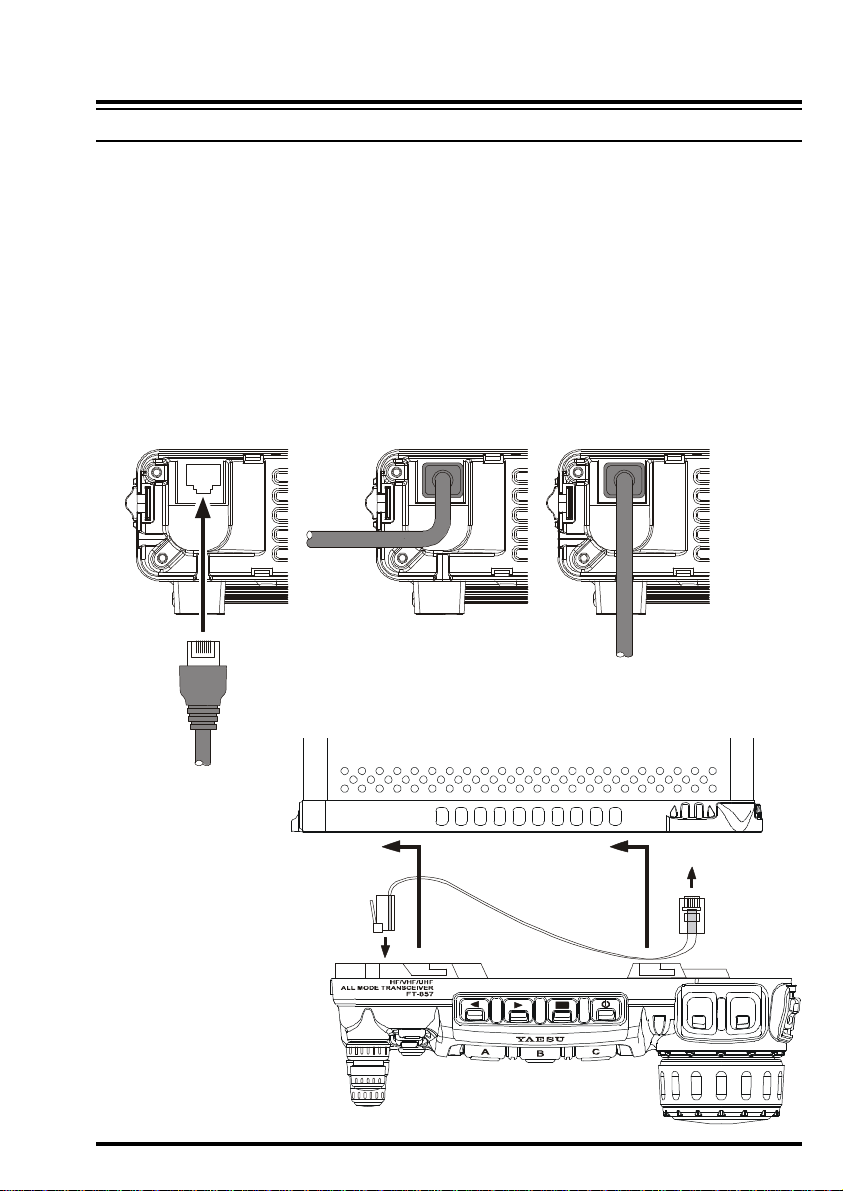
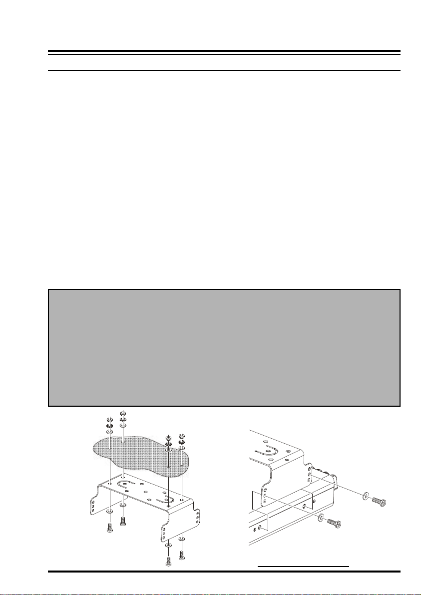
INSTALLING THE MICROPHONE AND FRONT PANEL
1. Insert the microphone’s plug into the recessed jack on the transceiver, as shown in the
illustration.
2. You may position the microphone cable so as to cause it to exit from the side or the
bottom of the transceiver. Just route the cable into the appropriate channel provided, as
shown in the illustration.
3. Connect the Control cable between the Front Panel and Transceiver Body.
4. Install the Front Panel by sliding it into the position shown; you will hear a “click” when
the panel locks into place.
5. To remove the Front Panel, use your left thumb to push rearward (slightly) the latch on
the left-hand of the panel, then slide the Front Panel to the right and away from the
transceiver.
MODE
DSP
TX/BUSY
DWN UP
7FT-857 Operating Manual
INSTALLATION
12V Battery
Cigarette Lighter Plug
FUSE: 25A
T
o
HF
/
5
0
MHz
An
t
e
n
n
aTo
144
MHz
/
430 MHz
Ante
nna
T
o HF/
5
0
MHz
A
nte
n
n
aTo 1
44
MHz
/
430 MHz
Ante
nna
VA005
5102015302040
CONTINUOUS CURRENT 25A
OVERLOAD
FP-1030A
RED
BLACK
FUSE: 25A
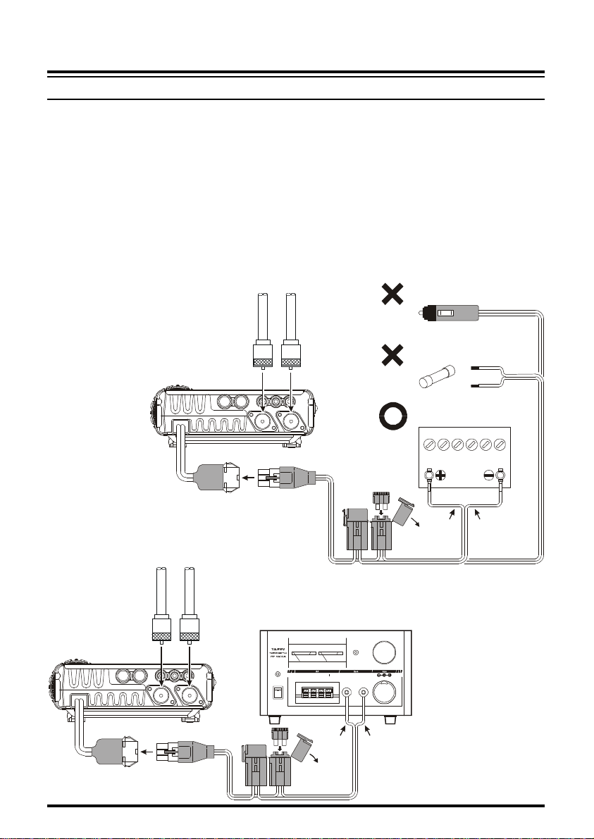
POWER CONNECTIONS
The DC power connector for the FT-857 must only be connected to a DC source providing
13.8 Volts DC (±15%), and capable of at least 22 Amperes of current. Always observe
proper polarity when making DC connections:
The Red DC power lead connects to the Positive (+) DC terminal; and the Black DC power
lead connects to the Negative (–) DC terminal.
In mobile installations, noise pickup may be minimized by connecting the DC cable directly
to your vehicle’s battery, rather than to the ignition switch or “accessory” circuitry. Direct
connection to the battery also provides the best voltage stability.
Fuse Box
8 FT-857 Operating Manual
Supplied DC Cable
Supplied DC Cable
POWER
ON
OFF
RED BLACK
INSTALLATION
POWER CONNECTIONS
Tips for Successful Mobile Installations:
r Before connecting the DC cable to the battery, measure the voltage across the battery
terminals with the engine running fast enough to show a charge. If the voltage is above
15 Volts, the vehicle’s voltage regulator should be adjusted to reduce the charging voltage to 14 Volts or lower.
r Route the DC cable as far away from the ignition cables as possible.
r If the DC cable is not long enough, use #12 AWG (minimum) stranded, insulated wire to
extend it. Be certain to solder the connections at the splice securely, and provide ample
insulation for the soldered splice (heat shrink tubing plus black electrical tape work
well).
r Check the battery terminal connections frequently to be sure they are tight and not cor-
roded.
r When operating with the vehicle turned off, or operating from a stand-alone car battery
(in a camp site, etc.), be mindful of the minimum operating voltage (11.73 Volts) for the
FT-857. If the battery is not charged sufficiently to maintain at least 11¾ Volts at the
radio, erratic operation or shut-down may occur.
Caution
Permanent damage can result if improper supply voltage, or reverse-polarity voltage,
is applied to the FT-857. The Limited Warranty on this transceiver does not cover
damage caused by application of AC voltage, reversed polarity DC, or DC voltage
outside the specified range of 13.8V ±15%. Never attempt to connect the FT-857 to
a 24-Volt battery system.
When replacing fuses, be certain to use a fuse of the proper rating. The FT-857
requires a 25A fast-blow fuse.
MMB-82 Installation
9FT-857 Operating Manual

INSTALLATION
GROUNDING
The provision of an effective ground system is important in any successful communications
station. A good ground system can contribute to station efficiency in a number of ways:
r It can minimize the possibility of electrical shock to the operator.
r It can minimize RF currents flowing on the shield of the coaxial cable and the chassis of
the transceiver which may cause interference to nearby home entertainment devices or
laboratory test equipment.
r It can minimize the possibility of erratic transceiver operation caused by RF feedback or
improper current flow through logic devices.
An effective earth ground system may take several forms; for a more complete discussion,
see an appropriate RF engineering text. The information presented below is intended only as
a guideline.
Inspect the ground system – inside the station as well as outside – on a regular basis so as to
ensure maximum performance and safety.
Mobile Station Grounding
Although satisfactory grounding in most installations will be achieved via the DC cable’s
negative lead and the antenna system’s coaxial cable shield, it is often recommended that
you provide a direct ground connection to the vehicle chassis at the mounting location of the
transceiver (installation using the MMB-82 Mounting Bracket will accomplish this, if the
MMB-82 itself is mounted to the vehicle’s chassis). Due to unexpected resonances which
may naturally occur in any location, improper communication system performance may
result from insufficient grounding. These symptoms may include:
r RF feedback (resulting in distortion on your transmitted signal);
r Unintended frequency change;
r Blinking or blanking of the frequency display;
r Noise pickup; and/or
r Loss of memory.
Note that these conditions may occur in any communications installation. The FT-857 includes extensive filtering designed to minimize the chance of such problems; however, random currents set up by insufficient RF grounding can nullify such filtering. Bonding the rear
panel Ground lug of the FT-857 transceiver to the vehicle or vessel’s ground system should
clear up any such difficulties.
Vertex Standard does not recommend the use of “on glass” mobile antennas unless the shield
of the coaxial cable is securely grounded near the feedpoint of the antenna. Such antennas
frequently are responsible for the ground-related difficulties described above.
10 FT-857 Operating Manual
INSTALLATION
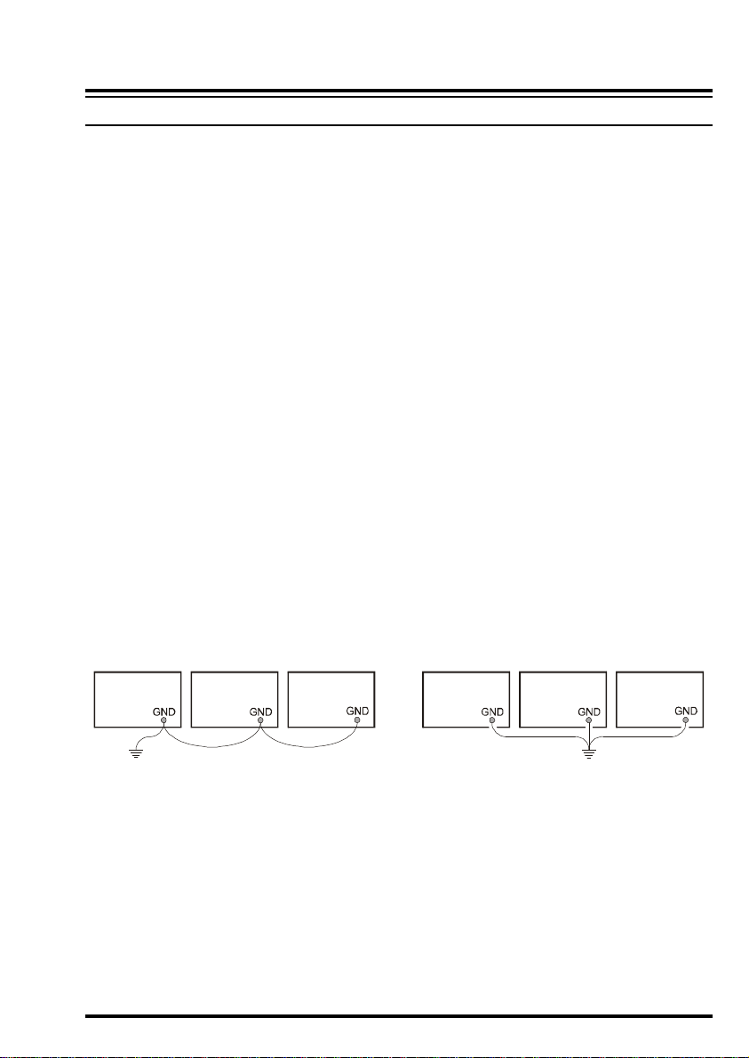
Proper Ground Connection
Amplifier
Power
Supply
Transceiver
Improper Ground Connection
GROUNDING
Base Station Earth Grounding
Typically, the ground connection consists of one or more copper-clad steel rods, driven into
the ground. If multiple ground rods are used, they should be configured in a “V” configuration, and bonded together at the apex of the “V” which is nearest the station location. Use a
heavy, braided cable (such as the discarded shield from type RG-213 coaxial cable) and
strong cable clamps to secure the braided cables to the ground rods. Be sure to weatherproof
the connections to ensure many years of reliable service. Use the same type of heavy, braided
cable for the connections to the station ground bus (described below).
Do not use gas line pipes in an attempt to provide a ground connection! To do so creates a
serious risk of explosion!!
Inside the station, a common ground bus consisting of a copper pipe of at least 1” (25 mm)
diameter should be used. An alternative station ground bus may consist of a wide copper
plate (single-sided circuit board material is ideal) secured to the bottom of the operating
desk. Grounding connections from individual devices such as transceivers, power supplies,
and data communications devices should be made directly to the ground bus using a heavy,
braided cable.
Do not make ground connections from one electrical device to another, and thence to the
ground bus. This so-called “Daisy Chain” grounding technique may nullify any attempt at
effective radio frequency grounding. See the drawings below for examples of proper and
improper ground connections.
Transceiver Linear
Amplifier
"Daisy Chain"
Power
Supply
Linear
11FT-857 Operating Manual

INSTALLATION
ANTENNA CONSIDERATIONS
The antenna systems connected to your FT-857 transceiver are, of course, critically important in ensuring successful communications. The FT-857 is designed for use with any antenna system providing a 50 W resistive impedance at the desired operating frequency. While
minor excursions from the 50 W specification are of no consequence, the power amplifier’s
protection circuitry will begin to reduce the power output of there is more than a 50% divergence from the specified impedance (less than 33 W or greater than 75 W, corresponding to
a Standing Wave Ratio (SWR) of 1.5:1).
Two antenna jacks are provided on the rear panel of the FT-857. The “HF/50 MHz ANT”
jack is used for HF and 50 MHz, while the “144/430 MHz ANT” jack is used for 144 MHz
and 430 MHz.
Guidelines for successful base and mobile station installations are shown below.
Mobile Antenna Installations
Mobile antennas for the HF bands, with the possible exception of those designed for 28
MHz, display very high “Q” due to the fact that they must be physically shortened, then
resonated using a loading coil. Additional system bandwidth may be realized using the Yaesu
FC-30 Automatic Antenna Tuner, which will present a 50 W impedance to your transceiver
on the 1.8 ~ 50 MHz bands so long as the SWR on the coaxial line connected to the FC-30
is below 3:1.
On the VHF and UHF bands, coaxial line losses increase so rapidly in the presence of SWR
that we recommend that all impedance matching to 50 W be performed at the antenna
feedpoint.
Yaesu’s Active-Tuned Antenna System (ATAS-100/-120) is a unique HF/VHF/UHF mobile antenna system, which provides automatic tuning when used with the FT-857. See page
68 for full details on the ATAS-100/-120.
For VHF/UHF weak-signal (CW/SSB) operation, remember that the antenna polarization
standard for these modes is horizontal, not vertical, so you must use a loop or otherwise
horizontally-polarized antenna so as to avoid cross-polarization loss of signal strength (which
can be 20 dB or more!). On HF, signals propagated via the ionosphere develop mixed polarizations, so antenna selection may be made strictly on mechanical considerations; vertical
antennas are almost always utilized on HF for this reason.
In mobile (and portable) installations, when vertical antennas are used, remember that the
grounding of the base area of the antenna is critically important to proper operation. Since
most HF vertical antennas emulate a quarter-wavelength “monopole” antenna, the “missing
half” of the dipole antenna consists of a counterpoise of radial ground system. In a vehicle,
if mounting the antenna to a door or hatch, it is recommended that you bond the door to the
12 FT-857 Operating Manual
INSTALLATION
ANTENNA CONSIDERATIONS
rest of the vehicle’s body, using a heavy braid bonded securely at both ends, to ensure that as
much counterpoise as possible is secured. In portable operation, be sure to lay out radials (or
otherwise construct a n image plane for the vertical monopole); it is not adequate simply to
connect a vertical radiating element to the rear panel Antenna jack of this transceiver, without providing a suitable counterpoise.
Base Station Antenna Installations
When installing a “balanced” antenna such as a Yagi or dipole, remember that the FT-857 is
designed for use with an (unbalanced) coaxial feedline. Always use a balun or other balancing device so as to ensure proper antenna system performance.
Use high-quality 50 W coaxial cable for the lead-in to your FT-857 transceiver. All efforts at
providing an efficient antenna system will be wasted if poor quality, lossy coaxial cable is
used. Losses in coaxial lines increase as the frequency increases, so a coaxial line with 0.5
dB of loss at 7 MHz may have 6 dB of loss at 432 MHz (thereby consuming 75% of your
transceiver’s power output!). As a general rule, smaller-diameter coaxial cables tend to have
higher losses than larger-diameter cables, although the precise differences depend on the
cable construction, materials, and the quality of the connectors used with the cable. See the
cable manufacturer’s specifications for details.
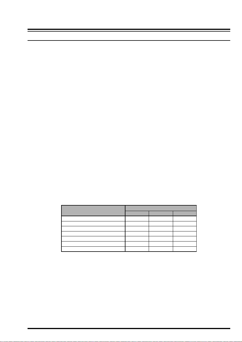
For reference, the chart below shows approximate loss figures for typically- available coaxial cables frequently used in HF installations.
Loss in dB per 30 m (100 feet) for Selected 50-ohm Coaxial Cables
CABLE TYPE
RG-58A
RG-58 Foam
RG-8X
RG-8A, RG-213
RG-8 Foam
Belden 9913
7/8” “Hardline”
Loss figures are approximate; consult cable manufacturer’s catalogs for complete specifications.
1.8 MHZ
0.55
0.54
0.39
0.27
0.22
0.18
< 0.1
LOSS
28 MHZ
2.60
2.00
1.85
1.25
0.88
0.69
0.25
432 MHZ
>10
8.0
7.0
5.9
3.7
2.9
1.3
Always locate antennas such that they can never come in contact with outdoor power lines in
the event of a catastrophic support or power-pole structural failure. Ground your antennas’
support structure(s) adequately, so as to dissipate energy absorbed during a lightning strike.
Install appropriate lightning arrestors in the antenna coaxial cables (and rotator cables, if
rotary antennas are used).
In the event of an approaching electrical storm, disconnect all antenna lead-in, rotator cables,
and power cables completely from your station if the storm is not immediately in your area.
13FT-857 Operating Manual

INSTALLATION
ANTENNA CONSIDERATIONS
Do not allow disconnected cables to touch the case of your FT-857 transceiver or accessories, as lightning can easily jump from the cable to the circuitry of your transceiver via the
case, causing irreparable damage. If a lightning storm is in progress in your immediate area,
do not attempt to disconnect the cables, as you could be killed instantly if lightning should
strike your antenna structure or a nearby power line.
If a vertical antenna is utilized, be certain that humans and/or pets and farm animals are kept
away both from the radiating element (to prevent electrical shock and RF exposure danger)
and the ground system (in the event of an electrical storm). The buried radials of a groundmounted vertical antenna can carry lethal voltages outward from the center of the antenna in
the event of a direct lightning strike.
RF FIELD EXPOSURE
This transceiver is capable of power output in excess of 50 Watts, so customers in the United
States may be required to demonstrate compliance with Federal Communications Commission (FCC) regulations concerning maximum permissible exposure to radio frequency energy. Compliance is based on the actual power output used, feedline loss, antenna type and
height, and other factors which can only be evaluated as a system.
Information regarding these regulations may be available from your Dealer, your local radio
club, from the FCC directly (press releases and other information can be found on the FCC’s
site on the World Wide Web at <http://www.fcc.gov>), or from the American Radio Relay
League, Inc. (225 Main St., Newington CT 06111 or <http://www.arrl.org>).
Although there is negligible radio frequency (RF) leakage from the FT-857 transceiver
itself, its antenna system should be located as far away from humans and animals as practicable, so as to avoid the possibility of shock due to accidental contact with the antenna or
excessive long-term exposure to RF energy. During mobile operation, do not transmit if
someone is standing adjacent to your antenna, and use the lowest power possible.
Never stand in front of an antenna (during testing or operation) when RF power is applied,
especially in the case of 430 MHz directional arrays. The 20 Watt power output supplied by
the FT-857, combined with the directivity of a beam antenna, can cause immediate heating
of human or animal tissues, and may cause other undesirable medical effects.
14 FT-857 Operating Manual
INSTALLATION
ELECTROMAGNETIC COMPATIBILITY
If this transceiver is used with, or in the vicinity of, a computer or computer-driven accessories, you may need to experiment with grounding and/or Radio Frequency Interference (RFI)
suppression devices (such as ferrite cores) to minimize interference to your communications
caused by energy from the computer. Computer-generated RFI is usually a result of inadequate shielding of the computer’s cabinet or I/O and peripheral connections. While computer equipment may “comply” with RF emission standards, this does not ensure that sensitive Amateur Radio receivers like the FT-857 will not experience interference from the
device!
Be certain to use only shielded cables for TNC-to-Transceiver connections. You may need
to install AC line filters on the power cord(s) of the suspected equipment, and decoupling
ferrite toroidal chokes may be required on interconnecting patch/data cables. As a last resort, you can try installing additional shielding within the computer’s case, using appropriate conductive mesh or conductive shielding tape. Especially check “RF holes” where plastic is used for cabinet front panels.
For further information, consult amateur radio reference guides and publications relating to
RFI suppression techniques.
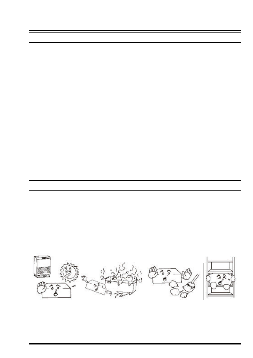
HEAT AND VENTILATION
To ensure long life of the components, be certain to provide adequate ventilation around the
cabinet of the FT-857. The cooling system of the transceiver must be free to draw cool air in
from the side of the transceiver and expel warm air from the rear of the transceiver.
Do not install the transceiver on top of another heat-generating device (such as a linear
amplifier), and do not place equipment, books, or papers on top of the transceiver. Place the
transceiver on a hard, flat, stable surface. Avoid heating vents and window locations that
could expose the transceiver to excessive direct sunlight, especially in hot climates.
Heat Water & Moisture Dust Ventilation
15FT-857 Operating Manual
INSTALLATION
REMOTE
ON
OFF
BAND DATA 1
BAND DATA 2
GND
ALC 2
ALC 1
PTT 2
PTT 1
INPUT 1
INPUT 2
CONTROL
DC48V IN
To HF AntennaTo HF AntennaTo 50 MHz AntennaINPUT 1
VL-1000
BAND-DATA 1CAT/LINEAR
nnaALC
1
CT-58 ALC Cable
GNDDC 48V INCONTROL
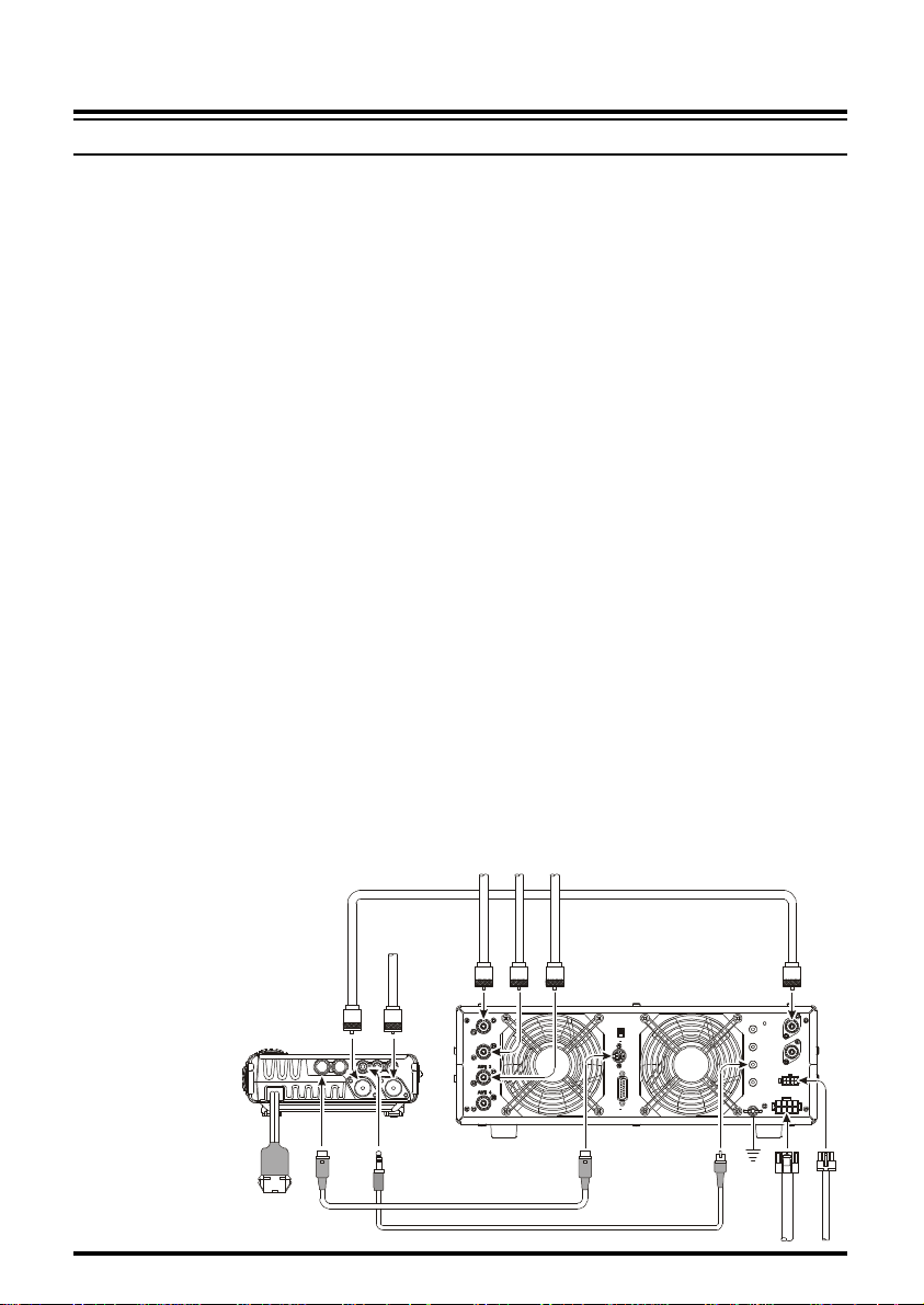
LINEAR AMPLIFIER INTERFACING
The FT-857 provides the switching and drive-control lines required for easy interfacing to
most all commonly-available amplifiers sold today.
These include:
r The Antenna Jacks (“HF/50MHz” and “144/430MHz”);
r A T/R control line (open circuit on RX, closure to ground on TX); and
r A negative-going ALC jack (control voltage range: 0V to –4V DC).
r When interfacing to the VL-1000 Solid State 1 KW Linear Amplifier, the optional CT-
58 Interface Cable provides for easy interconnection (requires that the Menu Mode No020 [CAT/LIN/TUN] setting changes to “LINEAR”).
The rear-panel CAT/LINEAR jack is an 8-pin, miniature DIN type, with the “TX GND” pin
providing a closure to ground on transmit, for T/R control of your linear amplifier. The ACC
jack is a miniature stereo type, with external ALC input capability on the tip connection. The
main shaft is the ground return. The ring connection of the ACC jack, when closed to ground,
places the FT-857 into the transmit mode, and sends a steady CW carrier, for amplifier (or
antenna tuner) adjustment purposes.
Note that some amplifiers, particularly VHF or UHF “brick” amplifiers, offer two methods
of T/R switching: application of +13V or a closure to ground.
Be sure to configure your amplifier so that it switches via a closure to ground, as provided
by your FT-857’s CAT/LINEAR jack (“TX GND” pin). Alternatively, many of these amplifiers use “RF Sensing” to control their relays; if yours is in this category, you may then use
the T/R control line from the “TX GND” pin
of the CAT/LINEAR jack for control of your
HF linear amplifier, and RF sensing for your
VHF or UHF amplifier.
ANT 1
ANT 2
ANT 3
ANT 1
To 144 / 430 MHz Ante
ANT 2
CT-58 BAND DATA Cable
16 FT-857 Operating Manual
INSTALLATION
COMMON
COMMON
DOT
GND
KEY
LINEAR AMPLIFIER INTERFACING
The “TX GND” T/R control line is a transistor “open collector” circuit, capable of handling
positive amplifier relay coil voltages of up to +50V DC and current of up to 400 mA. If you
plan on using multiple linear amplifiers for different bands, you must provide external bandswitching of the “TX GND” relay control line from the CAT/LINEAR jack.
Important Note!
Do not exceed the maximum voltage or current ratings for the “TX GND” line at the
CAT/LINEAR jack. This line is not compatible with negative DC voltages, nor AC
voltages of any magnitude.
Most amplifier control relay systems require only low DC voltage/current switching
capability (typically, +12V DC at 25 ~ 75 mA), and the switching transistor in the
FT-897 will easily accommodate such amplifiers.
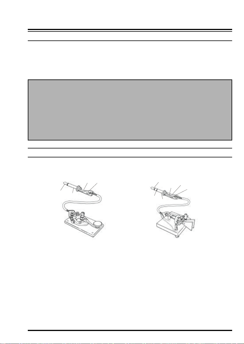
CW KEY/KEYER CONNECTIONS
All commonly-available keyer paddles should work perfectly with the built-in Electronic
Keyer. The wiring configuration for the paddle is shown below.
DASH
DOT
KEY
GND
DASH
For straight-key operation, only the tip and shaft connections are used.
Note: Even when using a straight key, you must use a three-conductor (“stereo”) plug. If a
two-conductor plug is used, the key line will be constantly shorted to ground.
When using an external electronic keyer, be absolutely certain that it is configured for “posi-
tive” keying, not “negative” or “grid block” keying. The “key-up” voltage of the FT-857 is
+5V, and the “key-down” current is only about 1 mA.
For CW automated keying using a personal computer, with an external memory keyer providing for manual sending, it usually is possible to connect the keyed lines together via a
“Y” connector. Check with the documentation accompanying your keyer and your contest/
DX software for any cautions which need to be observed.
17FT-857 Operating Manual
INSTALLATION
DATA
RECEIVER ACCESSORIES (TAPE RECORDER ETC.
Connection of a tape recorder or other such receiver accessory is
easily accomplished by using the DATA jack’s Data Out (1200 bps)
terminal (Pin 5) and Ground (Pin 2). The audio output is fixed at
100 mV, with an impedance of 600 W.
GND
)
DATA OUT
1200bps
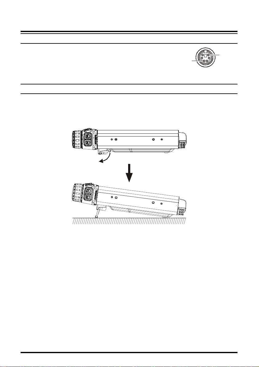
ADJUSTING THE FRONT FEET
The two front feet of the transceiver allow the transceiver to be tilted upward for better
viewing. Simply fold both feet forward to raise the front of the transceiver, and fold them
back against the bottom case to lower the front of the FT-857.
18 FT-857 Operating Manual

NOTE
INSTALLATION
19FT-857 Operating Manual
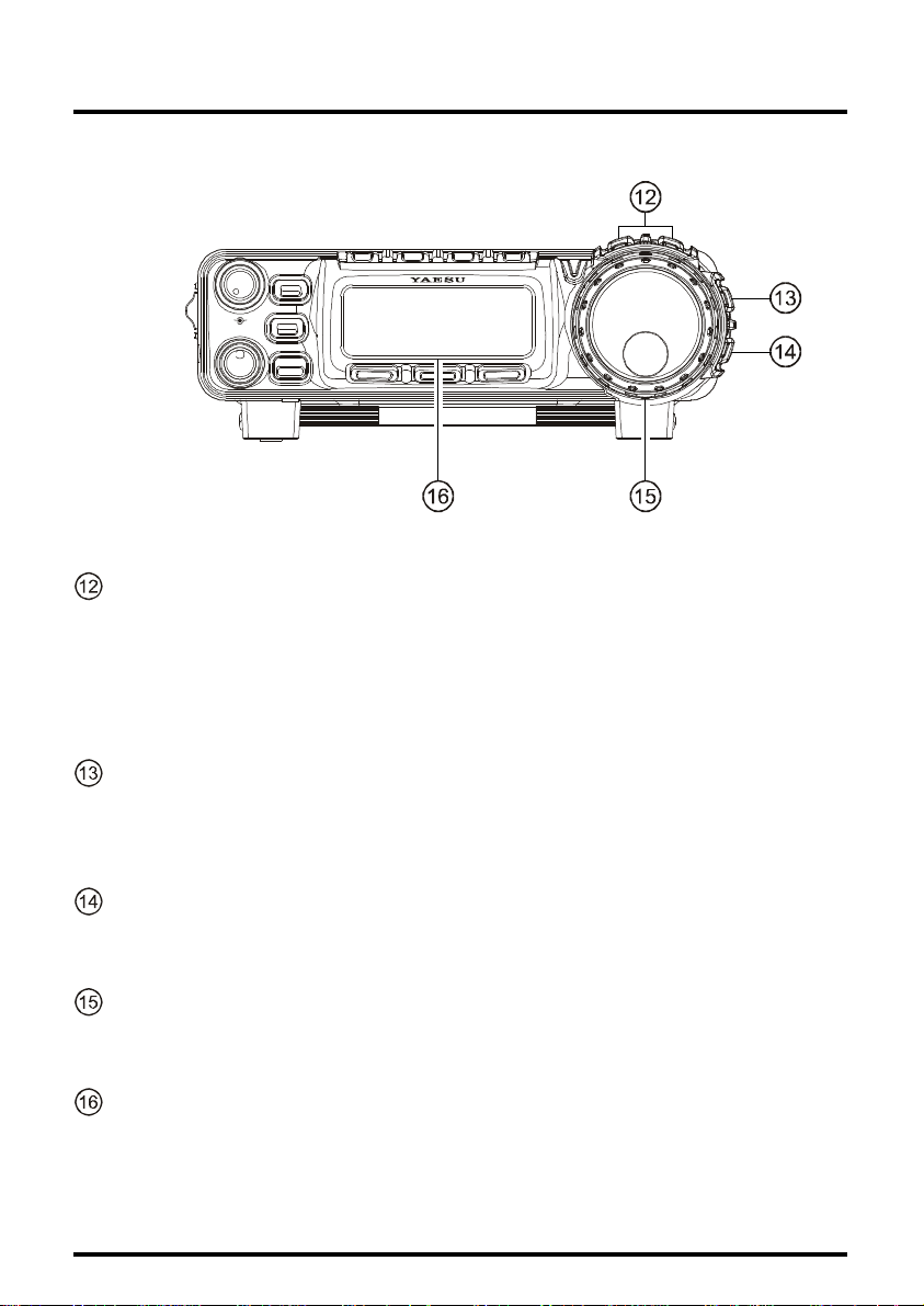
FRONT PANEL CONTROL & SWITCHES
HOME
CLAR
L
Q
A
S
F
F
R
/
E
C
L
E
T
S
FUNC
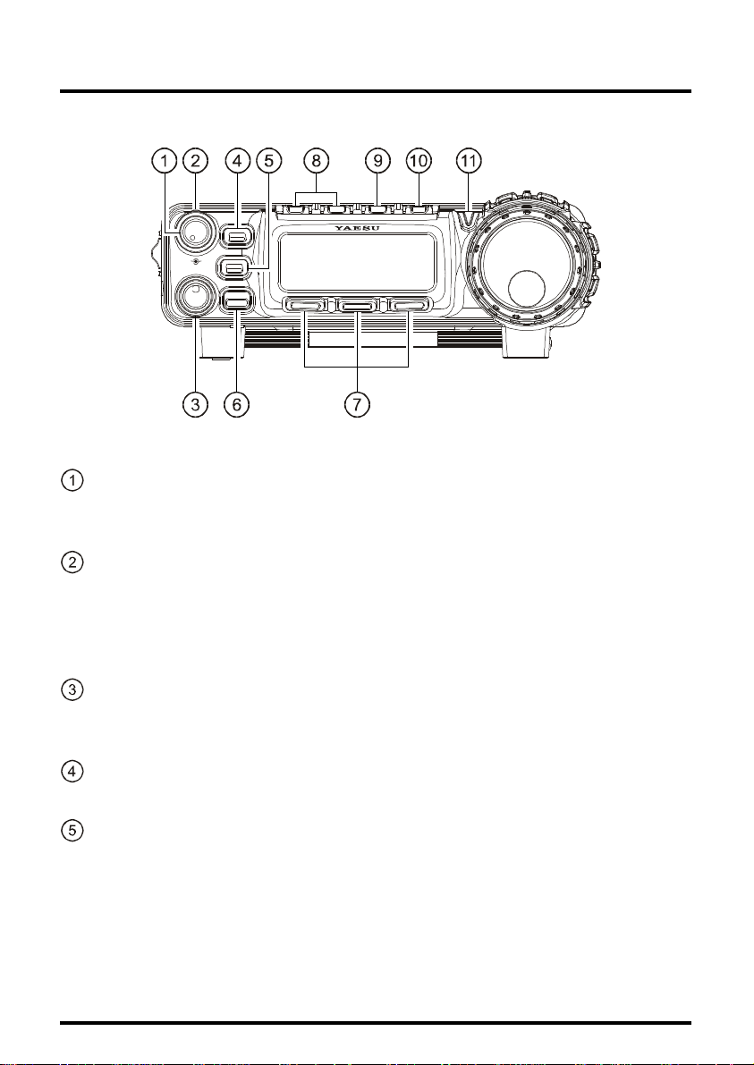
AF Knob
The (inner) VOL knob adjusts the receiver audio volume level presented to the internal
or external speaker. Clockwise rotation increases the volume level.
SQL/RF Knob
In the USA version, this (outer) SQL/RF knob adjusts the gain of the receiver’s RF and
IF stages. Using Menu Mode No-080 [SQL/RF GAIN], this control may be changed to
function as a Squelch control, which may be used to silence background noise when no
signal is present. In the other versions, its default setting is set to “Squelch.”
SELECT knob
This detented rotary switch is used for VFO frequency tuning, memory selection, and
function selection for the [A], [B], [C] keys of the transceiver.
HOME Key
Pressing this key momentarily recalls a favorite “Home” frequency memory.
CLAR Key
Pressing this key activates the Receiver Clarifier feature. When this feature is activated,
the SELECT knob is used to set a tuning offset of up to ±9.99 kHz. The transmitter’s
frequency is not affected by the setting of the Clarifier.
Press and hold in this key for one second to activate the IF Shift feature, which allows
you to use the SELECT knob to adjust the center frequency of the IF filter’s passband
response.
20 FT-857 Operating Manual

FRONT PANEL CONTROL & SWITCHES
FUNC Key
Press this key momentarily to enable the changing of the function of the Multi Function
keys ([A], [B], and [C]) by rotating the SELECT knob.
Press and hold in this key for one second to activate the “Menu” mode.
Multi Function Keys
These three keys select many of the most important operating features of the transceiver. When you press the [FUNC] key, then rotate the SELECT knob, the current
function of that key will appear above each of the [A], [B], and [C] keys (along the
bottom of the LCD). You may scroll the display through 17 rows of functions available
for use via the [A], [B], and [C] keys. The available features are shown in page 24.
MODE(t)/MODE(u) Key
Pressing either of these keys momentarily will change the operating mode. The selections available are:
.....
LSB ó USB ó CW ó CWR ó AM ó FM ó DIG ó PKT ó LSB
DSP Button
Pressing this button momentarily provides instant access to Multi Function Row “p”
(MFp), which contains the command key for the optional receiver’s Digital Signal Processing system. The available functions will appear as the functions displayed above the
[A], [B]
operation to the last-used Multi-Function Row (the one in use before the DSP row was
engaged).
Press and hold in this switch for one second to activate Menu Item No-048, for adjustment of the DSP Microphone Equalizer (see page 51 for details).
, and [C] keys, as described previously. Pressing this key once more will return
.....
POWER Switch
Press and hold in the POWER switch for one second to turn to the transceiver on or off.
While the transceiver is turned on, pressing this switch momentarily will engage the
“Fast Tuning” mode, to allow more rapid frequency navigation (a small “running man”
icon will be observed in the bottom right-hand corner of the LCD).
TX/BUSY Indicator
This indicator glows green when the squelch opens, and turns red during transmit. During CW operation, this indicator will glow blue when an incoming signal is tuned to the
center of the passband (with IF Shift off). And during FM reception, this indicator will
glow blue when a signal is received with a CTCSS/DCS tone matching that to which
your transceiver is set.
21FT-857 Operating Manual
FRONT PANEL CONTROL & SWITCHES
HOME
CLAR
L
Q
A
S
F
F
R
/
E
C
L
E
T
S
FUNC
BAND(DWN)/BAND(UP) Key
Pressing either of these keys momentarily will cause the frequency to be moved up or
down by one frequency band. The selections available are:
.....
1.8 MHz ó 3.5 MHz ó 5.0 MHz ó 7.0 MHz ó 10 MHz ó 14 MHz ó
15 MHz ó 18 MHz ó 21 MHzó 24 MHz ó 28 MHz ó 50 MHz ó
88 MHz ó 108 MHz ó 144 MHz ó 430 MHz ó 1.8 MHz
.....
V/M Key
Pressing this key switches frequency control between the VFO and Memory Systems.
Press and hold in this key to store the contents of the VFO into the QMB (Quick Memory
Bank) register.
LOCK Key
Pressing this key locks the front panel keys so as to prevent accidental frequency change.
The LOCK key itself, though, will never be disabled.
MAIN DIAL
This is the main tuning dial for the transceiver. It is used both for frequency tuning as
well as “Menu” setting in the transceiver.
Liquid Crystal Display
The Liquid Crystal Display (LCD) provides indication of the operating frequency and
other aspects of transceiver status.
22 FT-857 Operating Manual
FRONT PANEL CONTROL & SWITCHES
SIGNAL
GND
SIGNAL
GND
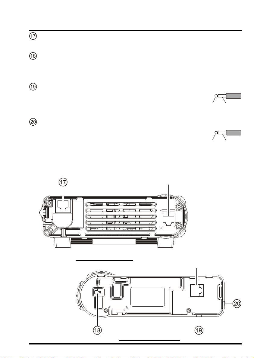
MIC Jack
Connect the supplied MH-31A8J Hand Microphone to this jack.
SP-PH Switch
If you use earphones with this transceiver, move this switch to the “PH” position before
inserting the earphone plug into the SP/PH Jack, to prevent injury your ears.
METER Jack
This 3.5-mm 2-pin jack is used for connection to an analog meter (not
produced by Vertex Standard). Please refer to the MENU, No-060 and
No-061.
SP/PH Jack
This 3.5-mm, 2-pin jack provides variable audio output for an external
speaker (4 W ~ 16 W impedance) or earphones. The audio level varies
according to the setting of the front panel’s AF knob.
Important Note: When you insert an earphone plug into this jack, the SP-PH slide
switch (located on the back side of front panel) MUST BE set to the “PH” position, to
prevent the possibility of injury to your ears.
CONTROL Jack
MAIN BODY (FRONT
PH SP
FRONT PANEL (BACK
)
CONTROL Jack
)
23FT-857 Operating Manual
FRONT PANEL CONTROL & SWITCHES
A
][]
[
FUNC
DIAL
SELECT
B][C
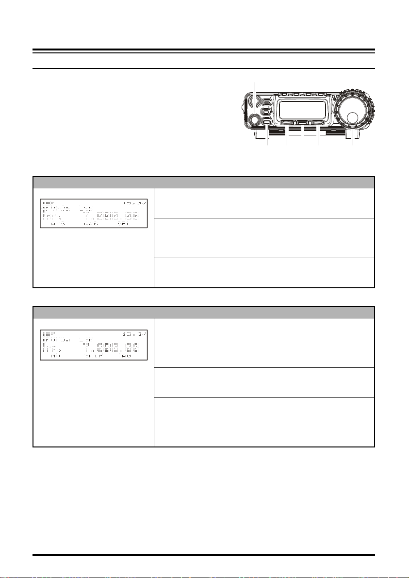
MULTI FUNCTION KEY DETAIL
The [A], [B], and [C] keys select many of the most
important operating features of the transceiver. When
you press the [FUNC] key, then rotate the SELECT
knob, the current function of that key will appear
above each of the [A], [B], and [C] keys (along the
bottom of the LCD). You may scroll the display
through 17 rows of functions available for use via the
[A], [B]
, and [C] keys.
][
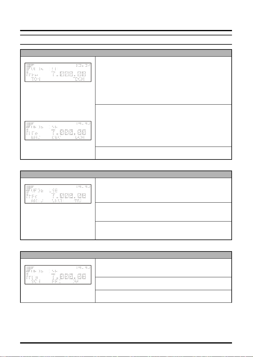
Multi Function Row “a” (MFa
Ó Ó Ó
[A] [B] [C]
Multi Function Row “b” (MFb
Ó Ó Ó
[A] [B] [C]
) [
A/B, A=B, SPL
[A]
Key: A/B
Press the [A](A/B) key to switch between VFO-A and VFO-B on the
display.
[B]
Key: A=B
Press the [B](A=B) key to copy the contents of Main VFO to be copied into the Sub VFO, so that the two VFOs’ contents will be identical.
[C]
Key: SPL
Press the [C](SPL) key to activate Split frequency operation between
VFO-A and VFO-B.
]
ô
) [
MW, SKIP, TAG
[A]
Key: MW
Press this key momentarily to enable the “Memory Check” mode, to
allow selection of an empty memory channel prior to frequency storage. Press and hold in the [A](MW) key for one second to transfer the
contents of the VFO into the selected Memory register.
[B]
Key: SKIP
Press the [B](SKIP) key to designate the current Memory channel to
be “skipped” during scanning.
[C]
Key: TAG
Press the [C](TAG) key to select the display type (Frequency or Alpha-numeric Tag) during Memory operation. Press and hold in this
key for one second, while on a recalled channel, to open Menu No.056, for quick programming of an Alphanumeric Tag.
]
ô
24 FT-857 Operating Manual
FRONT PANEL CONTROL & SWITCHES
MULTI FUNCTION KEY DETAIL
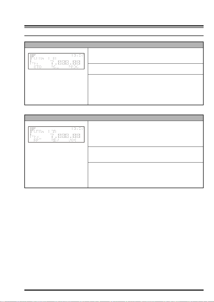
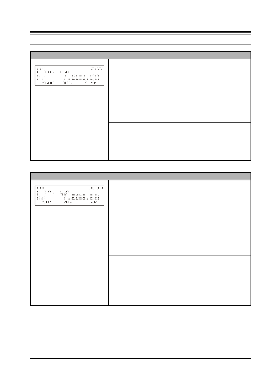
Multi Function Row “c” (MFc
Ó Ó Ó
[A] [B] [C]
Multi Function Row “d” (MFd
Ó Ó Ó
[A] [B] [C]
) [
STO, RCL, PROC
[A]
Key: STO
Press the [A](STO) key to store the contents of the VFO into the QMB
(Quick Memory Bank) register.
[B]
Key: RCL
Press the [B](RCL) key to recall the QMB Memory.
[C]
Key: PROC
Press the [C](PROC) key to activate the speech processor for SSB and
AM transmission.
Press and hold in the [C](PROC) key for one second to recall Menu
Mode No-074 [PROC LEVEL] (for setting the compression level of
the AF Speech Processor).
]
ô
) [
RPT, REV, VOX
[A]
Key: RPT
Press the [A](RPT) key to select the direction of the uplink frequency
shift (+, – or simplex) during FM repeater operation.
Press and hold in the [A](RPT) key for one second to recall Menu
Mode No-076 [RPT SHIFT] (for setting the shift frequency offset).
[B]
Key: REV
Press the [B](REV) key to reverse the transmit and receive frequencies while working through a repeater.
[C]
Key: VOX
Press the [C](VOX) key enable the VOX (voice-operated transmitter
switching system) in the SSB, AM, and FM modes.
Press and hold in the [C](VOX) key for one second to recall Menu
Mode No-088 [VOX GAIN] (for setting the VOX gain level).
]
ô
25FT-857 Operating Manual
FRONT PANEL CONTROL & SWITCHES
MULTI FUNCTION KEY DETAIL
Multi Function Row “e” (MFe
Ó Ó Ó
[A] [B] [C]
Ó Ó Ó
[A] [B] [C]
Multi Function Row “f” (MFf
Ó Ó Ó
[A] [B] [C]
Multi Function Row “g” (MFg
Ó Ó Ó
[A] [B] [C]
) [
TON, –––, TDCH] ([ENC, DEC, TDCH
[A]
Key: TON/ENC
Press the [A](TON) key to activate CTCSS or DCS operation on FM.
When the Split Tone feature is activated via Menu Mode No-079
[
SPLIT TONE], this key function changes to “ENC” for activation of
the CTCSS Encoder or DCS Encoder. Press the [A](ENC) key to activate the encoder.
Press and hold in the [A](TON/ENC) key for one second to recall Menu
Mode No-083 [TONE FREQ] (for selecting the CTCSS tone frequency).
[B]
Key: –––/DEC
Normally, this key does nothing.
When the Split Tone feature is activated via Menu Mode No-079
[
SPLIT TONE], this key function changes to “DEC” to engage the DCS
or CTCSS Decoder. Press the [B](DEC) key to activate the decoder.
Press and hold in the [B](DEC) key for one second to recall Menu
Mode No-033 [DCS CODE] (for selecting the DCS code).
[C]
Key: TDCH
Press the [C](TDCH) key to initiate CTCSS Tone or DCS Search.
])
ô
) [
ARTS, SRCH, PMS
[A]
Key: ARTS
Press the [A](ARTS) key to initiate the Auto-Range Transponder mode.
Press and hold in the [A](ARTS) key for one second to recall Menu
Mode No-008 [ARTS BEEP] (for selecting the ARTS “Beep” option).
[B]
Key: SRCH
Press the [B](SRCH) key to activate the Smart Search feature.
Press the [B](SRCH) key to initiate Smart Search scanning.
[C]
Key: PMS
Press the [C](PMS) key to activate the Programmable Memory Scan
feature (programmable sub-band limits for tuning or scanning).
]
ô
) [
SCN, PRI, DW
[A]
Key: SCN
Press the [A](SCN) key to initiate Scanning (in the direction of higher
frequencies).
[B]
Key: PRI
Press the [B](PRI) key to activate the Priority Scan feature.
[C]
Key: DW
Press the [C](DW) key to activate the Dual Watch feature.
]
ô
26 FT-857 Operating Manual
FRONT PANEL CONTROL & SWITCHES
MULTI FUNCTION KEY DETAIL
Multi Function Row “h” (MFh
Ó Ó Ó
[A] [B] [C]
Multi Function Row “i” (MFi
Ó Ó Ó
[A] [B] [C]
) [
SCOP, WID, STEP
[A]
Key: SCOP
Press the [A](SCOP) key to activate the Spectrum Scope Monitor feature.
Press and hold in the [A](SCOP) key for one second to initiate the
Spectrum Scope.
[B]
Key: WID
Press the [B](WID) key to select the visible bandwidth for the Spectrum Scope Monitor.
Press and hold in the [B](WID) key for one second to select the operating mode for the Spectrum Scope Monitor.
[C]
Key: STEP
Press the [C](STEP) key to select the channel steps for Spectrum Scope
Monitor.
Press and hold in the [C](STEP) key for one second to activate the
MAX HOLD feature, which will display and hold the peak signal
strength level for each channel.
]
ô
) [
MTR, –––, DISP
[A]
Key: MTR
Pressing the [A](MTR) key repeatedly allows selection of the display
function of the meter in the transmit mode.
PWR à ALC à SWR à MOD à PWR
The selected function will appear above the [B] key.
Press and hold in the [A](MTR) key for one second to recall Menu
Mode No-062 [MTR PEAK HOLD] (for setting the “peak-Hold” function of the meter).
[B]
Key
Pressing the [B] key repeatedly allows selection of the display function of the meter in the transmit mode.
PWR à MOD à SWR à ALC à PWR
[C]
Key: DISP
Press the [C](DISP) key to switch the display between the Large Character and Small Character modes. In the “Large Character” mode, the
VFO/Memory label and the Mode indication will disappear, as the
frequency display field is doubled in size.
Press and hold in the [C](DISP) key for one second to recall Menu
Mode No-043 [DISP INTENSITY] (for setting of the display brightness level).
]
......
......
ô
27FT-857 Operating Manual
FRONT PANEL CONTROL & SWITCHES
MULTI FUNCTION KEY DETAIL
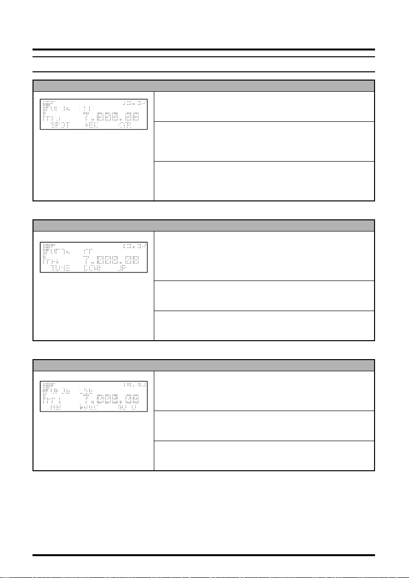
Multi Function Row “j” (MFj
Ó Ó Ó
[A] [B] [C]
Multi Function Row “k” (MFk
Ó Ó Ó
[A] [B] [C]
Multi Function Row “l” (MFl
Ó Ó Ó
[A] [B] [C]
) [
SPOT, BK, KYR
[A]
Key: SPOT
Press the [A](SPOT) key to activate the CW spotting heterodyne oscillator.
[B]
Key: BK
Press the [B](BK) key to enable CW “Semi-break-in” operation.
Press and hold in the [B](BK) key for one second to recall Menu Mode
No-029 [CW SIDE TONE] (for setting the CW side tone volume level).
[C]
Key: KYR
Press the [C](KYR) key to activate the built-in Electronic Keyer.
Press and hold in the [C](KYR) key for one second to recall Menu
Mode No-030 [CW SPEED] (for setting the Keyer speed).
]
ô
) [
TUNE, DOWN, UP
[A]
Key: TUNE
Press the [A](TUNE) key to activate the optional FC-30 Automatic
Antenna Tuner or ATAS-100/-120 Active-Tuning Antenna System.
Press and hold in the [A](TUNE) key for one second to initiate tuner
or antenna retuning.
[B]
Key: DOWN
Press and hold in the [B](DOWN) key to lower the ATAS-100/-120
antenna manually.
[C]
Key: UP
Press and hold in the [C](UP) key to raise the ATAS-100/-120 antenna manually.
]
ô
) [
NB, AGC, –––
[A]
Key: NB
Press the [A](NB) key to activate the receiver’s IF Noise Blanker.
Press and hold in the [A](NB) key for one second to recall Menu Mode
No-063 [NB LEVEL] (for setting of the NB level).
[B]
Key: AGC
Press the [B](AGC) key to disable the receiver’s AGC system. Normally, the AGC should be left On.
[C]
Key
Press the [C] key to select the recovery time (Slow, Fast, or Auto) for
the receiver’s AGC system.
]
ô
28 FT-857 Operating Manual
 Loading...