


VHF/UHF DUAL BAND FM TRANSCEIVER
FTM-10R
OPERATING MANUAL
VERTEX STANDARD CO., LTD.
4-8-8 Nakameguro, Meguro-Ku, Tokyo 153-8644, Japan
VERTEX STANDARD
US Headquarters
10900 Walker Street, Cypress, CA 90630, U.S.A.
YAESU EUROPE B.V.
P.O. Box 75525, 1118 ZN Schiphol, The Netherlands
YAESU UK LTD.
Unit 12, Sun Valley Business Park, Winnall Close
Winchester, Hampshire, SO23 0LB, U.K.
VERTEX STANDARD HK LTD.
Unit 5, 20/F., Seaview Centre, 139-141 Hoi Bun Road,
Kwun Tong, Kowloon, Hong Kong
VERTEX STANDARD (AUSTRALIA) PTY., LTD.
Normanby Business Park, Unit 14/45 Normanby Road Notting Hill 3168, Victoria, Australia

Contents
Features ............................................................. |
1 |
Front Panel & Top Panel ................................. |
4 |
Rear Panel & LCD ........................................... |
6 |
Accessories & Options ...................................... |
8 |
Supplied Accessories ..................................... |
8 |
Optional Accessories ...................................... |
9 |
Installation ...................................................... |
10 |
Preliminary Inspection ................................. |
10 |
Installation Tips ............................................ |
10 |
Safety Information ........................................ |
11 |
Mobile Installation ....................................... |
12 |
Base Station Installation ............................... |
14 |
Antenna Considerations ............................... |
15 |
Separate Installation ..................................... |
16 |
Non-Separate Installation ............................. |
21 |
Basic Operation .............................................. |
22 |
Receive ......................................................... |
22 |
Transmission ................................................ |
23 |
Smart Menu Features ..................................... |
24 |
AF Dual Function ......................................... |
25 |
ARTSTM ........................................................ |
26 |
Dimmer function .......................................... |
27 |
Horn Alert feature ........................................ |
27 |
Intercom Function ........................................ |
28 |
Monitor feature ............................................. |
28 |
Public Address feature ................................. |
29 |
Reverse feature ............................................. |
29 |
Scan feature .................................................. |
30 |
Smart SearchTM Operation ............................ |
30 |
Squelch Level Adjust ................................... |
31 |
TCALL ......................................................... |
32 |
TX Power Select .......................................... |
32 |
Intercom Volume Control ............................ |
32 |
Memory Operation ......................................... |
33 |
Memory Storage ........................................... |
33 |
Memory Recall ............................................. |
34 |
Memory Channel Customization .................. |
35 |
Memory Group Bank ............................... |
36 |
Memory Channel Number Change .......... |
37 |
Memory Channel Sort .............................. |
37 |
Labeling Memory ..................................... |
38 |
Scan Type ................................................. |
39 |
Skip/Preferential Scan Setting ................. |
39 |
Squelch Level ........................................... |
40 |
CTCSS frequency .................................... |
40 |
DCS code ................................................. |
41 |
CTCSS/DCS Operation ........................... |
41 |
Storing Independent Transmit |
|
Frequency (Odd Split) ....... |
42 |
Transmitter Power Level .......................... |
43 |
Deleting Memory ..................................... |
43 |
Club Channel Operation ................................ |
44 |
Recalling the Club Channel ......................... |
44 |
Activating the Club Channel Monitor .......... |
44 |
Message Feature ............................................. |
46 |
Programming a Message .............................. |
46 |
Programming a Member List ........................ |
47 |
Cloning the Message .................................... |
48 |
Set your Personal ID .................................... |
49 |
Sending a Messages ..................................... |
49 |
Cloning ......................................................... |
50 |
Changing the Club Channel frequency ........ |
52 |
Clock/Timer Operation .................................. |
53 |
Set up the Clock ........................................... |
53 |
Displays the Current Time ........................... |
54 |
Using the Stop Watch Timer ........................ |
55 |
Using the Interval Timer .............................. |
55 |
Convenience Features .................................... |
56 |
MUTE feature .............................................. |
56 |
LOCK ........................................................... |
56 |
Automatic Audio Volume Controller ........... |
56 |
AF-VFO feature ........................................... |
57 |
VOX Operation ............................................ |
57 |
VOX Sensitivity ........................................... |
58 |
Listening the AM/FM Broadcast Station ..... |
58 |
Time-Out Timer (TOT) ................................ |
58 |
Listening to external audio input .................. |
59 |
Bluetooth® Operation ..................................... |
60 |
AF Dual Function ........................................... |
62 |
CTCSS Operation ........................................... |
64 |
DCS Operation ............................................... |
65 |
EPCS (Enhanced Paging & |
|
Code Squelch) Operation ............ |
66 |
Internet Connection Feature (WIRESTM) .... |
68 |
DTMF Autodialer ........................................... |
71 |
Repeater Operation ........................................ |
73 |
Band Expansion .............................................. |
74 |
Weather Broadcast Channel Operation ....... |
75 |
Miscellaneous Setting ..................................... |
76 |
Channel Step Selection ................................ |
76 |
Changing the Operating Mode ..................... |
76 |
PTT key function .......................................... |
77 |
Key Beeper ................................................... |
77 |
Smart Key Select .......................................... |
77 |
Repeater Shift Direction ............................... |
78 |
Repeater Shift Offset .................................... |
78 |
Automatic Repeater Shift ............................. |
78 |
Programming the Key Assignments ............. |
79 |
Scanning Band ............................................. |
80 |
Scan-Resume Mode ...................................... |
80 |
Scan Direction .............................................. |
81 |
Scan Start Direction ..................................... |
81 |
Split Tone Operation .................................... |
82 |
CTCSS/DCS/EPCS Bell Operation ............. |
82 |
Battery Voltage Display ............................... |
83 |
Temperature Display .................................... |
83 |
Clock Format ................................................ |
83 |
Time System ................................................. |
84 |
Alarm Set ...................................................... |
84 |
Interval Beep ................................................ |
84 |
Automatic Power-Off (APO) ....................... |
85 |
Audio Pitch Control ..................................... |
85 |
Volume Setting Alert feature ....................... |
86 |
Speaker Selection ......................................... |
86 |
Stereo/Monaural Selection ........................... |
87 |
MIC Gain Setting ......................................... |
87 |
PTT Lock ..................................................... |
87 |
Menu (“Set”) Mode ........................................ |
88 |
Reset Procedure ............................................ |
101 |
Troubleshooting ............................................ |
102 |
Specifications ................................................ |
103 |

FEATURES
New Concept in Ultra compact Mobile transceivers
The ultra small size and design of this radio gives you many choices for mounting and using this radio in your vehicle. The front panel may be separated from the main unit providing many placement and mounting options even for motor cycles or off road vehicles. The microphone and the PTT switch are installed on the front panel so you can transmit without connecting any microphone. You will not need an additional microphone or cable to interfere with your driving on the road.
Simple set-up and no microphone or curl cord needed
The one touch, quick release front panel holder (new type) and the mounting bracket allow you to place the front panel anywhere you want. The newly designed mobile mounting bracket allows you to install or release the radio very easily.
The front panel has magnets and it is possible to install without using screws.
An angled panel adapter is included. The front panel may be adjusted up to 30 degrees inclination to allow an improved, comfortable operating position.
Convenient Operation
The large function dial and key buttons afford simple operation, even while wearing driving gloves. The shape, size and position of the keys have been studied carefully. The design will help avoid miss-operation of the keys while operating the vehicle.
Water proof front panel
The front panel is engineered to IP57 waterproof standards. You can mount the panel on the handle bar of a motorcycle.
Superb visibility with new LCD panel
The bright LED and the Ocean Blue color LCD assure comfortable viewing night or day.
FTM-10R OPERATING MANUAL |
1 |

FEATURES
Great new options to optimize your Motor Sports activities
-- Hands free operation with optional Bluetooth headset--
When the optional Bluetooth® stereo headset is used with the optional Bluetooth® unit and charger sleeve, you can enjoy comfortable hands free operation while you are driving. Using the high audio output external speaker, the magnetic mounting brackets and the Bluetooth® unit can provide hands-free operation and unlimited possibilities when using this radio in any Motor Sports activity.
Reliable and advanced performance
The final transmitter amplifier produces up to 50 watts VHF and 40 watts UHF of reliable and stable high power RF output.
The radio has wide receiving frequency capability, and an independent AM/FM broadcast receiver. The Amateur radio receiver is specially designed for optimal Amateur band operation, with improved adjacent channel selectivity and IMD performance. You will appreciate the superior performance of the receiver when operating in strong electro magnetic signal environments. The rugged chassis construction provides great reliability in any environment you may encounter on the car or the bike.
Loud Audio operation
A 2 inch diameter speaker. is mounted inside of the radio to provide powerful, low distortion AF output. The high volume will give excellent audio recognition, even in very noisy environments.
Also available is a MEK-200-M10 optional external speaker. You can have loud audio output with the 8 Watt AF amplifier built into the radio.
Sturdy rear chassis
A large aluminum die cast chassis forms a very sturdy rear case, and effectively radiates the heat from the RF amplifier without the need of a cooling fan. The sandwich construction of the chassis shields the electrical circuits from alternator and ignition noise. You have worry free operation during long hours of rough handling in harsh environments.
Advanced features to support many Motor Sport activities.
500 memory channels with alpha-numeric labels.
High output audio amplifier and optional external loudspeaker.
The PA (Public Address) function permits communicating with a loud voice.
The Intercom function provides communication through headphones between passengers in the vehicle. Also the Bluetooth® unit can be used for the intercom.
An AM /FM broadcast receiver is included. Audio line input is provided for connection to your iPod® (FM broadcast and external input have stereo audio available)
AF preset function alerts you when the AF audio level is changed by accident. You enjoy the appropriate and optimized setting of volume level.
2 |
FTM-10R OPERATING MANUAL |

FEATURES
The message send/receive function permits sending a programmable 16 character message with the transmitter’s ID. You can send your words by “Message” function even when the noise level at the opposite station is too high for audio communication.
The wireless clone feature permits the settings and data of the radio to be duplicated in other radios without connecting any wires. All the radios in your group traveling together can have the same settings with the easy setting operation.
A convenient stopwatch function and display includes a Lap counter, Interval Timer/ Alert and Time.
VOX is installed for hands free operation.
Many new features include: Tone Control, One-touch band selection, Automatic audio level control, Dimmer, TOT, WiRES, DC supply voltage indication, and APO.
FTM-10R OPERATING MANUAL |
3 |
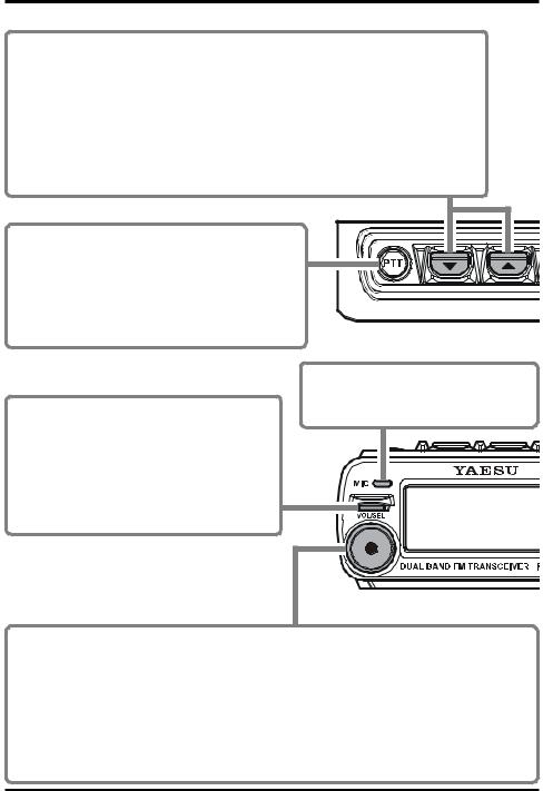
FRONT PANEL & TOP PANEL
 /
/ keys
keys
These keys select the following operations.
•AF Dual Feature (See page 25)
•ARTS Feature (See page 26)
•Reverse (See page 29)
•Scan Operation (See page 30)
•Display Dimmer (See page 27) • Smart Search Operation (See page 30)
•Horn Alert Feature (See page 27) • Squelch Threshold Level (See page 31)
• Intercom Operation (See page 28) |
• TCALL (See page 30) |
• Monitor Feature (See page 28) |
• TX Power Level (See page 32) |
•Public Address (See page 29)
•Volume Level Control while Intercom Operation (See page 32)
PTT keys
Press this key to transmit.
Speak into the microphone while pressing this key.
ΠRelease this key to return to receive.
ΠYou may change this key function to “toggle” mode (toggle the “transmit” and “receive” mode each time the key is pressed). (See page 77)
TX/BUSY Indicator
This indicator glows green when a signal is received.
This indicator glows red during transmission. This indicator blinks blue when a message is received.
This indicator glows white when transmitting a message.
MIC
The internal microphone is located here. Speak into the grill in a normal voice level while pressing the PTT key.
VOL/SEL key
You may adjust the receiver audio level with the DIAL knob after pressing this key.
ΠThe LED to the left of the DIAL knob will glow red when the DIAL knob is set to control the receiver audio level.
ΠPress this key again or wait for three seconds, to cancel control of the audio level by the
Dial knob. Mute Function:
Press and hold this key for one second to temporarily mute the receiver audio. Press this key again to restore the receiver audio.
4 |
FTM-10R OPERATING MANUAL |
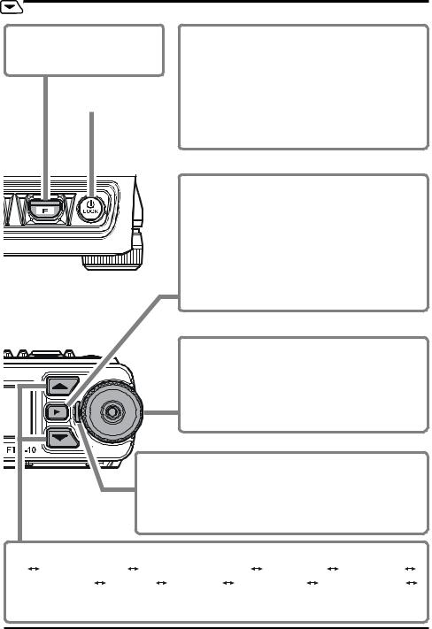
FRONT PANEL & TOP PANEL
|
key |
POWER key |
|
|
|||
Press this key to activate the |
Press and hold this key for two seconds to toggle the |
||
function that is selected by the |
transceiver’s power on or off. |
||
/ |
keys. |
Lock Function: |
|
|
|
|
Press this key momentarily while the transceiver is |
|
|
|
turned on to toggle the key lockout feature on or off. |
|
|
|
Π You may also lock out the PTT key when the |
|
|
|
LOCK mode is activated, by changing Menu Item |
|
|
|
“F22 PTT LOCK”. See page 87. |
 key
key
Π This key switches frequency control between the VFO and Memory System.
Π In the VFO mode, press and hold this key for one second to enter the Memory Write mode and then press this key again to store the frequency into the memory.
Π In the Memory mode, press and hold this key for one second to enter the Memory Channel Customization mode.
DIAL knob
Π Selects the operating frequency and also selects the memory channel.
Π Adjusts the receiver audio level when the LED to the left of the DIAL knob glows red.
Π Select the Smart Menu Item and parameter when the Smart Menu is activated.
LED
Π This LED glows red when adjusting the receiver audio level with the DIAL knob.
Π This LED blinks orange when the Volume Setting Alert feature is active.
Π This LED blinks yellow when the Timer feature is active.

 keys
keys
ΠPress these keys to switch the operating band as follows:
 2 m Amateur Band
  430 MHz Amateur Band
  FM BC Band
  AM BC Band
 WX Band
  Audio Line
  Group Channel
  2 m Amateur Band
ΠPress and hold this key for one second (MHz digits will blink), then rotate the DIAL knob to change the frequency in 1 MHz steps.
FTM-10R OPERATING MANUAL |
5 |

REAR PANEL & LCD
Stereo Audio |
Repeater Shift Direction CTCSS Operation |
||||||
S- & PO Meter |
|
|
|
|
Volume level |
||
|
|
|
|
DTMF Feature Active |
|||
Operating band |
|
|
|
|
|
|
Internet Connection |
|
|
|
|
|
|||
Club Channel Monitor |
|
|
|
|
Feature Active |
||
|
|
|
|
Memory Mode Selected |
|||
Feature Active |
|
|
|
|
|||
|
|
|
|
|
|||
Operating Frequency |
|
Digital Code Squelch (DCS) Operation |
|||||
|
|
|
|
||||
|
|
|
|
|
|
|
|
|
|
|
|
|
|
|
|
|
|
|
|
|
|
|
|
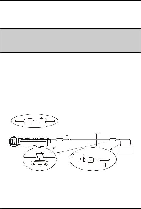
DC 13.8 V Cable Pigtail w/Fuse
Connect this pigtail to the car battery directly with the supplied DC cable. Π Connect the red lead to the positive side (+) of the battery and connect the
black lead to the negative side (-) of the battery. The DC cable is as short as possible, because transmitting requires a high DC electrical current flow.
Π Performance may be significantly reduced when connecting the DC cable to the cigarette lighter plug or fuse box.
Π Install a line filter if your vehicle has objectionable alternator noises.
ANT jack
Connect an efficient 144/430 MHz antenna, which is adjusted to 50-Ohm impedance. Use low-loss 50-Ohm coaxial cable with type-M (PL259) connector.
You may connect an optional CAB-1 Bluetooth® Head Set Charger Sleeve here.
You may connect an optional MEK-M10 Microphone Jack here.
6 |
FTM-10R OPERATING MANUAL |
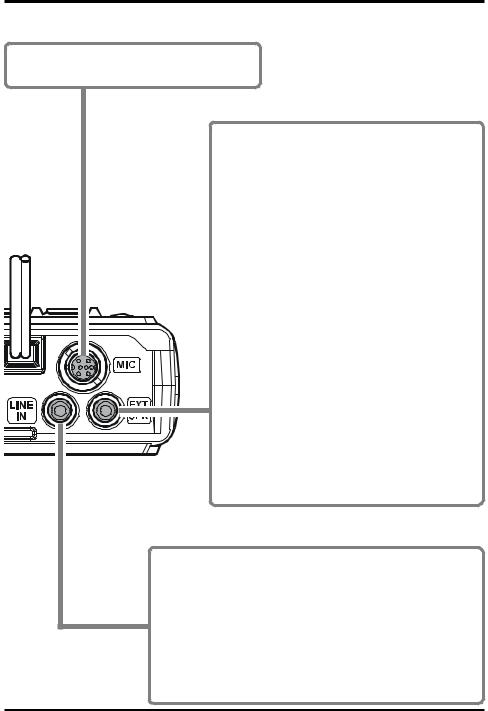
REAR PANEL
MIC jack
You may connect an optional MH-68A6J or MH68B6J Hand Microphone to this jack if you use.
EXT SPK jack
This 3-contact 3.5-mm mini stereo-phone jack provides receiver audio output for an optional external speaker. The audio impedance is 4 Ohms, and the level varies according to the setting of the front panel VOL control.
ΠInserting a plug into this jack disables audio from the transceiver's internal speaker.
ΠWhen stereo speakers are connected to this jack,
and the Menu item “F42 STEREO” is set to “STEREO”, you may enjoy FM Broadcast audio, or the external audio from the LINE IN jack in stereo.
Π If there is no audio output from the external speakers when connected to this jack, confirm that the Menu item “F34 SPEAKER” is set to “REAR” (See page 86).
Π Use of a sound isolating headset while driving on public roads is not lawful. An open type headset must be used for safety.
Hint: Menu Mode
The FTM-10R Smart Menu enables the configuration of 49 transceiver parameters to your favorite settings.
LINE IN jack
Connect an external audio source (such as the iPod® ) to this jack using the after-market audio cable.
When using the audio line input to this jack, you may enable the receiving of amateur signals while listening to your favorite music.
Adjust the input level with the volume control of the external audio equipment connected.
The connection cable depends on the external audio equipment you connect. Please ask your dealer.
FTM-10R OPERATING MANUAL |
7 |
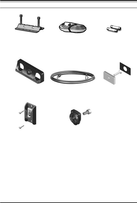
ACCESSORIES & OPTIONS
SUPPLIED ACCESSORIES
Mobile Mounting Bracket |
DC Power Cord W/Fuse |
Spare Fuse (15 A) |
Angle Adapter |
Separation Cable (3 m) |
Magnet |
Front Panel Bracket |
Front Panel Hanger |
Speaker Cable
Hex Wrench (4 mm)
Hex Wrench (3 mm)
Operating Manual
Warranty Card
8 |
FTM-10R OPERATING MANUAL |
ACCESSORIES & OPTIONS
OPTIONAL ACCESSORIES
MH-68A6J |
MH-68B6J |
MEK-M10 |
MLS-200-M10 |
DTMF Microphone |
Normal Microphone |
Microphone Jack |
High-Power External |
|
|
|
Speaker |
MMB-M10 |
MMB-M11 |
CT-M10 |
Multi-Angle Bracket |
Handle Bar Bracket |
Separation Cable (6 m) |
BH-1 |
BU-1 |
CAB-1 |
Bluetooth® Head Set |
Bluetooth® Adapter Unit |
Bluetooth® Head Set |
|
|
Charger Sleeve |
FEP-4 |
|
|
Ear Phone for BH-1 |
|
|
Availability of accessories may vary in some regions. This product is designed to perform optimally when used with genuine Vertex Standard accessories. Vertex Standard shall not be liable for any damage or accidents such as fire, leakage or explosion of batteries, etc., caused by the malfunction of non-Vertex Standard accessories. Consult your Vertex Standard dealer for details on these and any future available options. Connection of any nonVertex Standard-approved accessory, should it cause damage, may void the Limited Warranty on this apparatus.
FTM-10R OPERATING MANUAL |
9 |

INSTALLATION
This chapter describes the installation procedure for integrating the FTM-10R into a typical amateur radio station. It is presumed that you possess technical knowledge and conceptual understanding consistent with your status as a licensed radio amateur. Please take some extra time to make certain that the important safety and technical requirements detailed in this chapter are followed closely.
PRELIMINARY INSPECTION
Inspect the transceiver visually immediately upon opening the packing carton. Confirm that all controls and switches work freely, and inspect the cabinet for any damage. Gently shake the transceiver to verify that no internal components have been shaken loose due to rough handling during shipping.
If any evidence of damage is discovered, document it thoroughly and contact the shipping company (or your local dealer, if the unit was purchased over-the-counter) so as to get instructions regarding the prompt resolution of the damage situation. Be certain to save the shipping carton, especially if there are any punctures or other evidence of damage incurred during shipping. If it is necessary to return the unit for service or replacement, use the original packing materials. Then put the entire package inside another packing carton to preserve the evidence of shipping damage for insurance purposes.
INSTALLATION TIPS
To ensure long life of the components, be certain to provide adequate ventilation around the cabinet of the FTM-10R.
Do not install the transceiver on top of another heat-generating device (such as a power supply or amplifier). Avoid heating vents and window locations that could expose the transceiver to excessive direct sunlight, especially in hot climates. The FTM-10R should not be used in an environment where the ambient temperature exceeds +140 °F (+60 °C).
10 |
FTM-10R OPERATING MANUAL |

INSTALLATION
SAFETY INFORMATION
The FTM-10R is an electrical apparatus, as well as a generator of High RF (Radio Frequency) energy. You should exercise all safety precautions that are appropriate for this type of device. These safety tips apply to any device installed in a well-designed amateur radio station.
Never allow unsupervised children to play in the vicinity of your transceiver or antenna installation.
Be certain to wrap any wire or cable splices thoroughly with insulating electrical tape, to prevent short circuits.
Do not route cables or wires through doorjambs or other locations where they may become frayed and shorted to ground or to each other.
Do not stand in front of a directional antenna while you are transmitting into that antenna. Do not install a directional antenna in any location where humans or pets
may walk in the main directional lobe of the antenna's radiation pattern.
In mobile installations, it is preferable to mount the antenna on top of the vehicle, if feasible, this will utilize the car body as a counterpoise and raise the radiation pat-
tern as far away from passengers as possible.
During mobile operation when stopped (in a parking lot, for example), make it a practice to switch to Low power if there are people walking nearby.
 Never wear dual-earmuff headphones while driving a vehicle.
Do not attempt to drive your vehicle while making a telephone or auto patch call while using the optional DTMF microphone. Pull over to the side of the road, whether
dialing manually or using the auto-dial feature.
Warning!: High RF voltage is present in the TX RF section of the transceiver while transmitting. Do not touch the TX RF section while transmitting.
FTM-10R OPERATING MANUAL |
11 |

INSTALLATION
MOBILE INSTALLATION
The FTM-10R must only be installed in vehicles having a 13.8 Volt negative ground electrical system. Mount the transceiver where the display, controls, and microphone are easily accessible, using the supplied Mobile Mounting Bracket.
The transceiver may be installed in almost any location, but should not be positioned near a heating vent or anywhere where it might interfere with driving (either visually or mechanically). Make sure to provide plenty of space on all sides of the transceiver so that air can flow freely around the radio’s case.
An antenna and an antenna cable are not included in the box. Purchase them separately to accommodate your transceiver installation.
The DC power cable draws a large current when transmitting. The power cable should be wired as short as possible, and connected directly to the battery. (Do not use the cigarette lighter socket for power connections).
Never remove the fuse holders from the DC cables Never connect the transceiver directly to a 24 V battery.
Select a low-loss coaxial cable to connect the transceiver with the antenna. Use the shortest length possible.
Select a quality, high efficiency VHF/UHF antenna, and mount it in a good location on the car to obtain the maximum performance from the transceiver. (NOTE: An antenna designed with a matching device that forms a low DC resistance to ground may have poor reception on the AM broadcast band.)
The antenna depends on good grounding to realize maximum performance. Contact your dealer for information on transceiver and antenna installation.
If alternator noise exists, use a line filter in the DC power cable connection.
IMPORTANT: Select a location which can support the weight of the FTM-10R transceiver and does not interfere with your driving.
12 |
FTM-10R OPERATING MANUAL |
INSTALLATION
Mobile Power Connections
To minimize voltage drop and avoid blowing the vehicle's fuses, connect the supplied DC power cable directly to the battery terminals. Do not attempt to defeat or bypass the DC cable fuse - it is there to protect you, your transceiver, and your vehicle's electrical system.
Warning!
Never apply AC power to the power cable of the FTM-10R, nor DC voltage greater than 15.8 Volts. When replacing the fuse, use only a 15-A fuse. Failure to observe these safety precautions will void the Limited Warranty on this product.
Before connecting the transceiver, check the voltage at the battery terminals while revving the engine. If the voltage exceeds 15 Volts, repair the vehicle’s voltage regulator before proceeding with installation.
Connect the RED power cable lead to the POSITIVE (+) battery terminal, and the BLACK power cable lead to the NEGATIVE (-) terminal. If you need to extend the power cable, use #12 AWG or larger insulated, stranded copper wire. Solder the splice connections carefully, and wrap the connections thoroughly with insulating electrical tape.
Before connecting the cable to the transceiver, verify the voltage and polarity of the voltage at the transceiver end of the DC cable using a DC voltmeter. Now connect the transceiver to the DC cable.
FTM-10R |
Cabin » |
¼ Engine Room |
|
|
|||
|
RED:Positive (+) |
Battery |
|
|
BLACK:Negative (-) |
|
|
Mobile Speakers
The optional MLS-200-M10 High-Power External Speaker includes its own swivel-type mounting bracket, and is available from your Yaesu dealer.
Other external speakers may be used with the FTM-10R, if they present the specified 8- Ohm impedance and are capable of handling the 8 Watts of audio output supplied by the
FTM-10R.
FTM-10R OPERATING MANUAL |
13 |

INSTALLATION
BASE STATION INSTALLATION
The FTM-10R is ideal for base station use as well as in mobile installations. The FTM-10R is specifically designed to integrate into your station easily, using the following information as a reference.
AC Power Supplies
Operation of the FTM-10R from an AC line requires a power supply capable of providing at least 9 Amps continuously at 13.8 Volts DC. The FP-1025A and FP-1030A DC Power Supplies are available from your Yaesu dealer to satisfy these requirements. Other wellregulated power supplies may be used if they meet the above voltage and current specifications.
Use the DC power cable supplied with your transceiver to make power connections to the power supply. Connect the RED power cable lead to the POSITIVE (+) power supply terminal, and connect the BLACK power cable lead to the NEGATIVE (-) power supply terminal.
14 |
FTM-10R OPERATING MANUAL |

INSTALLATION
ANTENNA CONSIDERATIONS
The FTM-10R is designed for use with antennas presenting an impedance of near 50 Ohms at all operating frequencies. To avoid damage that could result if transmission occurs accidentally without an antenna, the antenna (or a 50 Ohm dummy load) should be connected whenever the transceiver is turned on.
Ensure that your antenna is designed to handle 50 Watts of transmitter power. Some mag- netic-mount mobile antennas, designed for use with hand-held transceivers, may not be capable of withstanding this power level. Consult the antenna manufacturer's specification sheet for details.
Use high-quality 50-Ohm coaxial cable for the lead-in to your FTM-10R transceiver. All efforts at providing an efficient antenna system will be wasted if poor quality, “lossy” coaxial cable is used. Losses in coaxial lines increase as the frequency increases, so an 8- meter-long (25’) coaxial line with under 1 dB of loss at 144 MHz may have a loss of 3 dB or more at 446 MHz. Choose your coaxial cable carefully based on the installation location (mobile vs. base) and the overall length of the cable required. (For very short runs of cable in a mobile installation, the smaller, more flexible cable types may be acceptable.)
For reference, the chart below shows approximate loss figures for typically available coaxial cables frequently used in VHF/UHF installations.
Loss in dB per 30 m (100 feet) for Selected 50-Ohm Coaxial Cables
(Assumes 50-Ohm Input/Output Terminations)
CABLE TYPE |
LOSS: 144 MHZ |
LOSS: 430 MHZ |
RG-58A |
6.5 |
> 10 |
RG-58 Foam |
4.7 |
8 |
RG-213 |
3.0 |
5.9 |
RG-8 Foam |
2.0 |
3.7 |
Belden 9913 |
1.5 |
2.9 |
Times Microwave LMR-400 |
1.5 |
2.6 |
7/8” “Hardline” |
0.7 |
1.3 |
Loss figures are approximate; consult cable manufacturers’ catalogs for complete specifications.
In outdoor installations, be certain to weatherproof all connectors thoroughly, as water entering a coaxial cable will cause losses to escalate rapidly, thus diminishing your communications effectiveness. The use of the shortest possible length of the highest quality coaxial cable that fits within your budget will ensure the best performance from your FTM-10R.
Your dealer should be able to assist you with all aspects of your antenna installation requirements.
FTM-10R OPERATING MANUAL |
15 |

INSTALLATION
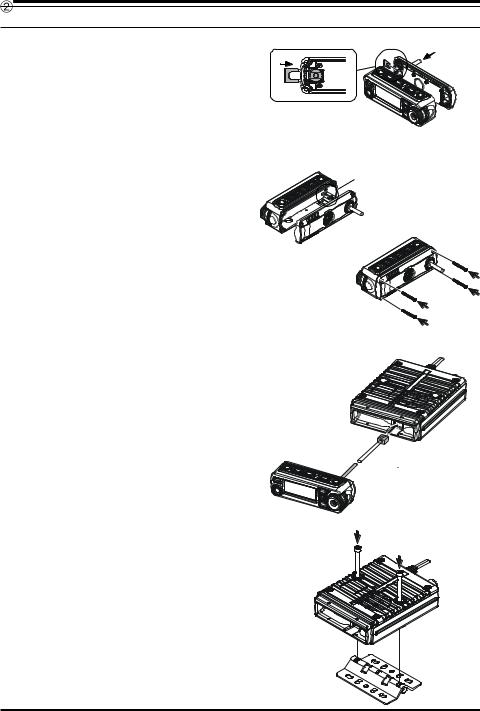
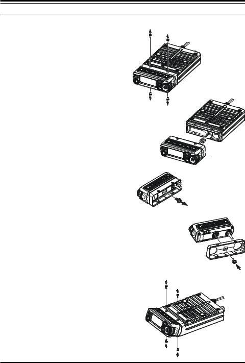
SEPARATE INSTALLATION
1. |
Remove the four screws securing the |
|
|
Front Panel and then remove the Front |
|
|
Panel from the Transceiver Body |
|
|
(Figure 1). |
|
2. |
Disconnect the 8-pin modular plug |
|
|
from the Transceiver (Figure 2). |
|
3. |
Remove the screw affixing the Straight |
|
|
Sub Panel, and then remove the |
|
|
Straight Sub Panel from the Front Panel |
Figure 1 |
|
(Figure 3). |
|
4. |
Remove the four screws securing the |
|
|
Rear Case of the Front Panel and re- |
|
|
move the Rear Case from the Front |
|
|
Panel (Figure 4). Disconnect the Con- |
|
|
nector of the Connection Cable from |
|
|
the Printed Circuit Board in the Front |
|
|
Panel when you remove the Rear Case |
|
|
(Figure 5). |
|
5. |
Remove the Binding Plate from the |
|
|
Rear Case (Figure 6- ), and then pull |
|
|
out the Connection Cable from the Rear |
|
|
Case (Figure 6- ). |
|
Figure 2
Figure 3
Figure 4
connector
Figure 5
Figure 6
16 |
FTM-10R OPERATING MANUAL |
INSTALLATION
SEPARATE INSTALLATION
6.Insert the supplied 3-m Connection Cable from the rear side of Rear Case (Figure 7- ), and then attach the Connection Cable to the Rear Case using the previously removed Binding Plate
(Figure 7- ).
6.Attach the Connection Cable to the Printed Circuit Board (Figure 8), and then replace the Rear Case to the Front Panel using the previously removed four screws (Figure 9).
7.Connect the 8-pin modular plug of the Connection Cable to the Transceiver
(Figure 10).
9.Mount the supplied Mobile Mounting Bracket to the any position using the supplied screws (Figure 11).
Figure 7
connector
Figure 8
Figure 9
 Figure 10
Figure 11
FTM-10R OPERATING MANUAL |
17 |
INSTALLATION
SEPARATE INSTALLATION
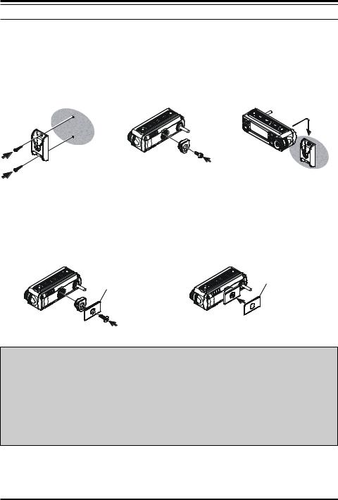
Front Panel Installation
Use the supplied Front Panel Bracket;
1. Mount the supplied |
2. Connect the supplied |
3. Install the Front Panel |
Front Panel Bracket to |
Front Panel Hanger |
into the Front Panel |
the any positions using |
using the supplied |
Bracket. |
the supplied two screws. |
screw. |
|
Use the supplied Magnet;
1.Connect the supplied Magnet and Front Panel Hanger using the supplied screw .
Magnet
2.Affix the supplied Protection Seal to the Magnet.
Protection Seal
CAUTION!
ΠIf the protective film is not affixed to the magnet, it may damage the mounting surface.
ΠDamage is possible even if the protection film is attached.
ΠBe careful handling the hanger. The strong magnet could pinch your fingers.
ΠEven with the strong magnet, it is possible to displace the bracket.
ΠThe magnet may destroy data on banking & identification cards.
18 |
FTM-10R OPERATING MANUAL |
INSTALLATION
SEPARATE INSTALLATION
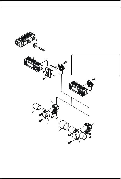
Use the Optional Multi-Angle Bracket “MMB-M10”;
1.If you use the Front Panel as Microphone, Connect the supplied Front Panel Hanger using the supplied screw.
2.Mount the supplied Front Panel Bracket to the “MMB-M10” using the supplied two screws.
3.If you do not use the Front Panel as a Microphone, install the Front Panel directly to the “MMB-M10”.
FTM-10R OPERATING MANUAL |
19 |
INSTALLATION
SEPARATE INSTALLATION
Use the Optional Handle Bar Bracket “MMB-M11”;
1.If you use the Front Panel as Microphone, Connect the supplied Front Panel Hanger using the supplied screw.
2.Bracket and Rubber are selected by the size of installed Bar (Refer to the table below).
If you do not use the Front Panel as a Microphone, install the Front Panel directly to the “MMB-M11”.
Bracket (S)
Rubber (S-a: t=1 mm)
Bracket (L)
Rubber (S-b: t=2 mm)
Rubber (L-a: t=1 mm)
|
|
Rubber (L-b: t=3 mm) |
|
|
|
|
|
Bar |
Bracket |
Rubber |
|
7/8” |
S |
S-a & S-b |
|
1” |
S-a |
|
|
|
|
||
1-1/4” |
L |
L-a & L-b |
|
1-1/2” |
L-a |
|
|
|
|
||
20 |
FTM-10R OPERATING MANUAL |
INSTALLATION
NON-SEPARATE INSTALLATION
The FTM-10R front panel may be tilted using the supplied Angle Sub Panel.
1.Remove the four screws securing the Front Panel and then remove the panel from the transceiver body (Figure 1).
2.Disconnect the 8-pin modular plug from the transceiver (Figure 2).
3.Remove the screw affixing the Straight Sub Panel, and then remove the Straight Sub Panel from the Front Panel (Figure 3).
4.Attach the supplied Angle Sub Panel to the Front Panel, using the previously removed screw.
You may set this up in a “look-up” or “look-down” configuration depending on the mounting position of the Sub Panel.
5.Connect the 8-pin modular plug to the transceiver’s body.
6.Attach the Front Panel (with Angle Sub Panel) to the transceiver’s body, using the previously removed four screws (Figure 5).
Figure 1
Figure 2
Figure 3
Figure 4
Figure 5
FTM-10R OPERATING MANUAL |
21 |
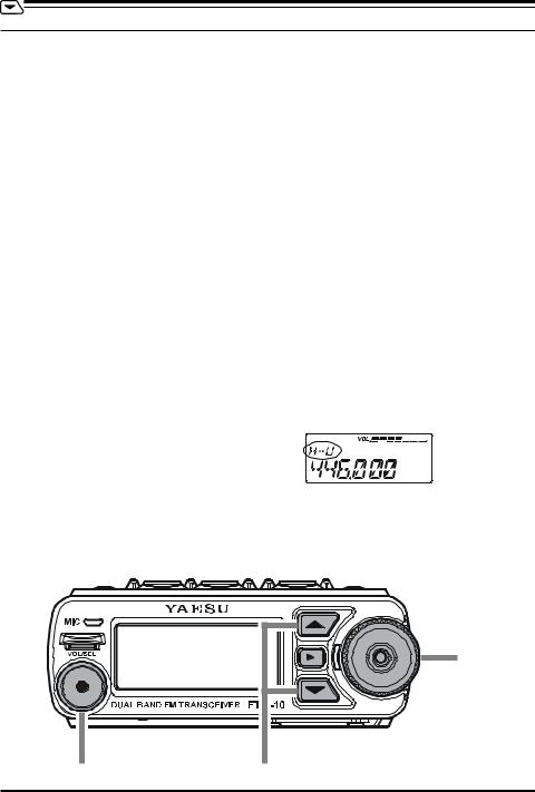
BASIC OPERATION
RECEIVE
1.To turn the transceiver on, press and hold in the top panel [POWER] key for two seconds.
When you turn the transceiver on, the applied DC voltage is displayed on the LCD for
2 seconds. Then the operating frequency will be displayed.
To turn the transceiver off, press and hold in the [POWER] key for two seconds.
2.Press the front panel  /
/ keys to switch the operating band as follows:
 Key
Key
2 m Amateur Band (H-V) 430 MHz Amateur Band (H-U) FM BC Band (FM)
AM BC Band (AM) WX Band (WX) Audio LineÚ Group Memory (GRP) |
2 |
||
m Amateur Band (H-V) |
|
|
|
|
Key |
|
|
|
|
|
|
2 m Amateur Band (H-V) |
Group Memory (GRP) Audio LineÚ WX Band (WX) |
||
AM BC Band (AM) |
FM BC Band (FM) 430 MHz Amateur Band (H-U) |
2 m |
|
Amateur Band (H-V) |
|
|
|
ÚWhen external audio equipment, like an iPod®, is connected, an after-market cable is required.
When external audio equipment is connected, the input audio level must be adjusted on the external audio equipment.
H-U |
430 MHz Amateur Band |
|
|
|
|
|
|
|
|
|
|
|
|
|
|
|
|
||||
H-V |
144 MHz Amateur Band |
|
|
|
|
|
|
|
|
|
|
|
|
|
|
|
|
|
|
|
|
GRP |
Group Memory |
|
|
|
|
|
|
|
|
|
-- |
Audio Line |
|
|
|
|
|
|
|
|
|
WX |
WX Band |
|
|
|
|
|
|
|
|
|
AM |
AM BC Band |
|
[POWER] key |
|||||||
FM |
FM BC Band |
|
|
|
|
|
|
|
|
|
|
|
|
|
|
|
|
||||
|
|
|
|
|
|
|
|
|
|
|
|
|
DIAL knob |
[VOL/SEL] key |
/ |
key |
22 |
FTM-10R OPERATING MANUAL |

BASIC OPERATION
3.Rotating the DIAL knob tunes the frequency in pre-programmed steps. Clockwise rotation of the DIAL knob will increase the frequency; counter-clockwise rotation will lower the operating frequency.
4.Press and hold in one of the front panel  /
/ keys for one second (the 1 MHz digit will blink). Then rotate the DIAL knob to change the frequency at 1 MHz per step. This feature is extremely useful for making rapid frequency excursions over the wide tuning range of the FTM-10R.
5.Press the [VOL/SEL] key until the red LED to the left of the DIAL knob illuminates and the volume level is displayed on the LCD. Now, the DIAL knob becomes the volume knob.
6.Rotate the DIAL knob to adjust the receiver volume. Clockwise rotation increases the audio output level.
TRANSMISSION
1.Press the front panel  /
/  keys to switch the operating band to 144 MHz or 430 MHz band.
2.Press the PTT (Push To Talk) key on the front panel when the frequency is clear. Speak into the microphone on the front panel (upper left corner of the front panel) in a normal voice level.
When talking around 3 feet away from the front panel microphone, the modulation may not be enough and the transmitted audio level may be lower.
3.When your transmission is complete, release the PTT key. The transceiver will revert to the receive mode.
PTT key
MIC
FTM-10R OPERATING MANUAL |
23 |
SMART MENU FEATURES
The FTM-10R top panel  /
/ keys, and the
  key select and enable operation of the following features:
|
|
|
|
|
|
|
|
|
|
|
|
|
|
|
|
|
|
|
|
|
|
|
|
|
|
|
|
|
|
|
|
|
|
|
|
|
|
|
|
|
|
|
|
|
|
|
|
|
|
|
|
|
|
|
|
|
|
|
|
|
|
|
|
|
|
|
|
|
|
|
|
|
|
|
|
|
|
|
|
|
|
|
|
|
|
|
|
|
|
|
|
|
|
|
|
|
|
|
|
|
|
|
|
|
|
|
|
|
|
|
|
|
|
|
|
|
|
|
|
|
|
|
|
|
|
|
|
|
|
|
|
|
|
|
|
|
|
|
|
|
|
|
|
|
|
|
|
|
|
|
|
|
|
|
|
|
|
|
|
|
|
|
|
|
|
|
|
|
|
|
|
|
|
|
|
|
|
|
|
|
|
|
|
|
|
|
|
|
|
|
|
|
|
|
|
|
|
|
|
|
|
|
|
|
|
|
|
|
|
|
|
|
|
|
|
|
|
|
|
|
|
|
|
|
|
|
|
|
|
|
|
|
|
|
|
|
|
|
|
|
|
|
|
|
|
|
|
|
|
|
|
|
|
|
|
|
|
|
|
|
|
|
|
|
|
|
|
|
|
|
|
|
|
|
|
|
|
|
|
|
|
|
|
|
|
|
|
|
|
|
|
|
|
|
|
|
|
|
|
|
|
|
|
|
|
|
|
|
|
|
|
|
|
|
|
|
|
|
|
|
|
|
|
|
|
|
|
|
|
|
|
|
|
|
|
|
|
|
|
|
|
|
|
|
|
|
|
|
|
|
|
|
|
|
|
|
|
|
|
|
|
|
|
|
|
|
|
|
|
|
|
|
|
|
|
|
|
|
|
|
|
|
|
|
|
|
|
|
|
|
|
|
|
|
|
|
|
|
|
|
|
|
|
|
|
|
|
|
|
|
|
|
|
|
|
|
|
|
|
|
|
|
|
|
|
|
|
|
|
|
|
|
|
|
|
|
|
|
|
|
|
|
|
|
|
|
|
|
|
|
|
|
|
|
|
|
|
|
|
|
|
|
|
|
|
|
|
|
|
|
|
|
|
|
|
|
|
Select the function |
[F] key |
||||||||||||||||||||||||||
|
|
|
|
|
|
|
|
|
|
|
|
|
|
|
|
|
|
|
|
|
|
|
|
|
|
|
|
|
|
|
|
|
|
|
|
|
|
|
|
|
|
|
|
|
|
|
|
|
|
|
|
|
|
|
|
|
|
|
|
|
|
|
|
|
|
|
|
|
|
|
|
|
|
|
|
|
|
|
|
|
|
|
|
|
|
|
|
|
|
|
|
|
Display |
|
|
|
|
|
|
|
|
|
|
|
|
|
|
Function |
|
|
|
|
|
|
|
|
|
|
|
|
|
|
|
|
|
|
|
||||||||||
|
AF DUAL |
|
Press the |
|
|
|
|
|
|
|
key to activate the AF Dual function which enables receiv- |
||||||||||||||||||||||||||||||||||
|
|
|
|
|
|
|
|||||||||||||||||||||||||||||||||||||||
|
|
|
|
|
ing an Amateur Band signal while listening to the signal of an FM Broad- |
||||||||||||||||||||||||||||||||||||||||
|
|
|
|
|
cast Station at the same time. |
|
|
|
|
|
|
|
|
|
|
|
|
|
|
|
|
|
|
|
|||||||||||||||||||||
|
ARTS |
|
Press the |
|
|
|
|
|
|
|
key to activate the ARTS feature. |
|
|
|
|
|
|
|
|
|
|
|
|
|
|
|
|
|
|
|
|||||||||||||||
|
|
|
|
|
|
|
|
|
|
|
|
|
|
|
|
|
|
|
|
|
|
|
|
|
|||||||||||||||||||||
|
|
|
|
|
|
|
|
|
|
|
|
|
|
|
|
|
|
|
|
|
|
|
|
|
|
|
|
|
|
|
|
|
|
|
|
|
|
|
|
|
|
|
|
|
|
|
DIMMER |
|
Press the |
|
|
|
|
|
|
|
key to enable adjustment of the display illumination level |
||||||||||||||||||||||||||||||||||
|
|
|
|
|
|
||||||||||||||||||||||||||||||||||||||||
|
|
|
|
|
by the DIAL knob. |
|
|
|
|
|
|
|
|
|
|
|
|
|
|
|
|
|
|
|
|||||||||||||||||||||
|
HORN 1 |
|
Press the PTT switch to activate the sound of a Gong Bell. |
||||||||||||||||||||||||||||||||||||||||||
|
HORN 2 |
|
Press the PTT switch to activate the sound of a UFO in flight. |
||||||||||||||||||||||||||||||||||||||||||
|
HORN 3 |
|
Press the PTT switch to activate the sound of a klaxon. |
||||||||||||||||||||||||||||||||||||||||||
|
HORN 4 |
|
Press the PTT switch to activate the sound of a siren. |
||||||||||||||||||||||||||||||||||||||||||
|
INTERCOM |
|
Press the |
|
|
|
|
|
|
|
key to activate the Intercom mode. |
|
|
|
|
|
|
|
|
|
|
|
|
|
|
|
|
|
|
|
|||||||||||||||
|
|
|
|
|
|
|
|
|
|
|
|
|
|
|
|
|
|
|
|
|
|
|
|
|
|||||||||||||||||||||
|
|
|
|
|
|
|
|
|
|
|
|
|
|
|
|
|
|
|
|
|
|
|
|
|
|
|
|
|
|
|
|
|
|
|
|
|
|
|
|
|
|
|
|
|
|
|
MONI |
|
Press the |
|
|
|
|
|
|
key to disable noise and tone squelch. |
|||||||||||||||||||||||||||||||||||
|
|
|
|
|
|||||||||||||||||||||||||||||||||||||||||
|
|
|
|
|
|
|
|
|
|
|
|
|
|
|
|
|
|
|
|
|
|
|
|
|
|
|
|
|
|
|
|
|
|
|
|
|
|
|
|
|
|
|
|
|
|
|
PA |
|
Press the PTT switch to route your amplified voice through the PA |
||||||||||||||||||||||||||||||||||||||||||
|
|
|
|
|
speaker. |
|
|
|
|
|
|
|
|
|
|
|
|
|
|
|
|
|
|
|
|
|
|
|
|
|
|
|
|
|
|
|
|
||||||||
|
REVERSE |
|
Press the |
|
|
|
|
|
|
key to activate the Reverse feature. |
|
|
|
|
|
|
|
|
|
|
|
|
|
|
|
|
|
|
|
||||||||||||||||
|
|
|
|
|
|
|
|
|
|
|
|
|
|
|
|
|
|
|
|
|
|
|
|
||||||||||||||||||||||
|
|
|
|
|
|
|
|
|
|
|
|
|
|
|
|
|
|
|
|
|
|
|
|
|
|
|
|
|
|
|
|
|
|
|
|
|
|
|
|
|
|
|
|
|
|
|
SCAN |
|
Press the |
|
|
|
|
|
|
key to activate the scanner. |
|
|
|
|
|
|
|
|
|
|
|
|
|
|
|
|
|
|
|
||||||||||||||||
|
|
|
|
|
|
|
|
|
|
|
|
|
|
|
|
|
|
|
|
|
|
|
|
||||||||||||||||||||||
|
|
|
|
|
|
|
|
|
|
|
|
|
|
|
|
|
|
|
|
|
|
|
|
|
|
|
|
|
|
|
|
|
|
|
|
|
|
|
|
|
|
|
|
|
|
|
SQL LEVL |
|
Press the |
|
|
|
|
|
key to enable adjustment of the noise squelch threshold |
||||||||||||||||||||||||||||||||||||
|
|
|
|
|
|||||||||||||||||||||||||||||||||||||||||
|
|
|
|
|
level by the DIAL knob. |
|
|
|
|
|
|
|
|
|
|
|
|
|
|
|
|
|
|
|
|||||||||||||||||||||
|
SSCH |
|
Press the |
|
|
|
|
|
key to activate the Smart Search. |
|
|
|
|
|
|
|
|
|
|
|
|
|
|
|
|
|
|
|
|||||||||||||||||
|
|
|
|
|
|
|
|
|
|
|
|
|
|
|
|
|
|
|
|
|
|
|
|
||||||||||||||||||||||
|
|
|
|
|
|
|
|
|
|
|
|
|
|
|
|
|
|
|
|
|
|
|
|
|
|
|
|
|
|
|
|
|
|
|
|
|
|
|
|
|
|
|
|
|
|
|
TCALL |
|
Press the |
|
|
|
|
|
key to activate the 1750 Hz Tone Burst. |
||||||||||||||||||||||||||||||||||||
|
|
|
|
|
|||||||||||||||||||||||||||||||||||||||||
|
|
|
|
|
|
|
|
|
|
|
|
|
|
|
|
|
|
|
|
|
|
|
|
|
|
|
|
|
|
|
|
|
|
|
|
|
|
|
|
|
|
|
|
|
|
|
TX POWER |
|
Press the |
|
|
|
|
|
key to change the transmit power level. |
||||||||||||||||||||||||||||||||||||
|
|
|
|
|
|||||||||||||||||||||||||||||||||||||||||
|
|
|
|
|
|
|
|
|
|
|
|
|
|
|
|
|
|
|
|
|
|
|
|
|
|
|
|
|
|
|
|
|
|
|
|
|
|
|
|
|
|
|
|
|
|
|
VOL.ITCOM |
|
Press the |
|
|
|
|
key to change the receiver audio level of the intercom |
|||||||||||||||||||||||||||||||||||||
|
|
|
|
|
|||||||||||||||||||||||||||||||||||||||||
|
|
|
|
|
receiver. |
|
|
|
|
|
|
|
|
|
|
|
|
|
|
|
|
|
|
|
|
|
|
|
|
|
|
|
|
|
|
|
|
||||||||
Advice: When one of the above features does not appear in the list, it is because that feature is not assigned to the top panel  /
/  keys. Please insure the Menu “F14 FKEY MOD” is set to “FNC” or “FNC+MSG”.
24 |
FTM-10R OPERATING MANUAL |
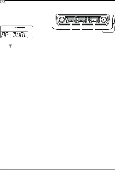
SMART MENU FEATURES
AF DUAL FUNCTION
With the “AF DUAL” function, it is possible to monitor your desired amateur band frequency while receiving AM, FM broadcast or Audio from the external input jack.
You may select: AM broadcast, FM broadcast, Club Channel or external line input, by changing the Menu Item “F2 AF DUAL” (The factory default is AM broadcast receiving).
1. |
Set the FTM-10R to the desired amateur band frequency by the VFO or Memory chan- |
||||||
|
nel selection. |
|
|
|
|
|
|
2. |
Press the top panel / |
key to select “AF DUAL”. |
|
|
|||
|
|||||||
3. |
Press the |
key to activate the AF Dual function. |
|
|
|
|
|
|
|
|
|||||
Π By first setting the desired VFO or memory channel in 


 step #1 above, and then starting “AF DUAL” function, both the amateur signals and the AM broadcast station will be received.
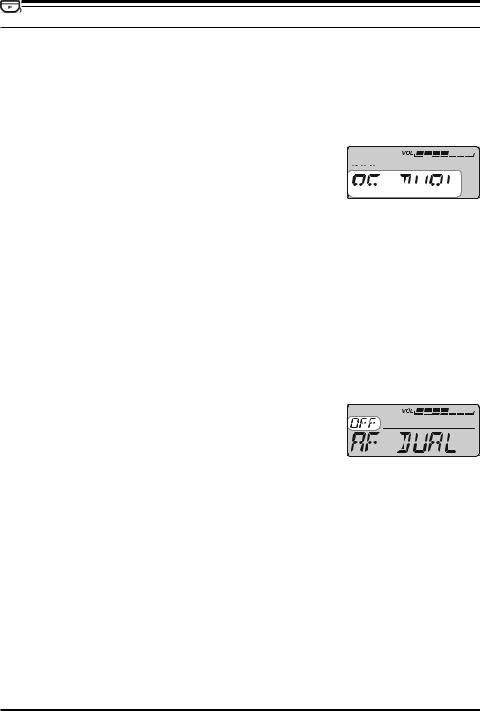
4.Rotate the DIAL knob to select the desired AM Broadcast station.
ΠYou may switch the AM Broadcast Band frequency control between the VFO and Memory channel by pressing the  key.
key.
ΠWhen a signal is received in the amateur band, the AM Broadcast audio is muted. When the amateur band signal drops, the AF Dual function is resumed (monitor the amateur band frequency while receiving the AM broadcast).
ΠYou may transmit on the frequency set in step1 by pressing the PTT key, even if the AF Dual function is activated.
To disable the AF Dual function, press the front panel |
|
/ |
|
keys. |
||||
|
|
|||||||
Π When the |
|
key function is set to “AF DUAL” via the |
|
|||||
|
|
|||||||
top panel / |
key, the |
|
key may be used to toggle |
|
||||
|
|
|||||||
the “AF DUAL” on/off.
FTM-10R OPERATING MANUAL |
25 |

SMART MENU FEATURES
ARTSTM
The ARTS feature uses DCS signaling to inform both parties when you and another ARTS equipped station are within communications range. This may be particularly useful during Search and Rescue situations, where it is important to stay in contact with other members of your group.
Both stations must set up their DCS codes to the same code number, then activate their ARTS feature using the command appropriate for their radio. Alert ringers may be activated, if desired.
Whenever you push the PTT key, or every 25 seconds after ARTS is activated, your radio will transmit a signal which includes a (subaudible) DCS code 


for about 1 second. If the other radio is in range, the beeper will sound (if enabled) and the display will show “IN.RANGE”, otherwise the out of range display “OUT.RANGE” will be dis-
play during ARTS operation.
Whether you talk or not, the polling every 25 seconds will continue until you de-activate ARTS. When ARTS is de-activated,
DCS will also be deactivated (if you were not using it previously in nonARTS operation).
If you move out of range for more than one minute (four pollings), your radio will sense that no signal has been received. Three beeps will sound, and the display will revert to “OUT.RANGE”. If you move back into range, your radio will again beep, and the display will change back to the “IN.RANGE” indication.
During ARTS operation, your operating frequency will continue to be displayed, but no changes may be made to it or other settings. You must terminate ARTS in order to resume normal operation. This is a safety feature designed to prevent accidental loss of contact due to channel change, etc.
1.Set the FTM-10R to the desired amateur band frequency by the VFO or Memory channel selection.
2.Set your radio and the other radio(s) to the same DCS code number per the discussion on page 65.
2.Press the top panel  /
/ key to select “ARTS”.
3.Press the  key. You will observe the “OUT.RANGE” display on the LCD. The ARTS operation has now commenced.
4.Every 25 seconds, your radio will transmit a “polling” call to the other station. When that station responds with its own ARTS polling signal, the display will change to “IN.RANGE” to confirm that the other station’s polling code was received in response to yours.
5.When the  key function is set to “ARTS” via the top panel
  /
/ key, the
  key may be used to toggle the “ARTS” on/off.
26 |
FTM-10R OPERATING MANUAL |
|
|
|
|
SMART MENU FEATURES |
||||||
|
|
|
|
|
|
|
|
|
|
|
|
|
|
|
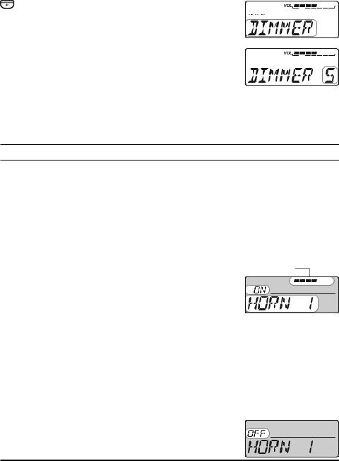
DIMMER FUNCTION |
||||||
You may adjust the display dimmer level. |
||||||||||
1. |
Press the top panel / |
key to select “DIMMER”. |
|
|
|
|
|
|
||
|
|
|
|
|
||||||
2. |
Press the |
|
key. |
|
|
|
|
|
|
|
|
|
|
|
|
|
|
|
|||
|
|
|
|
|
|
|
|
|||
|
|
|
|
|
|
|
|
|
|
|
3. |
Rotate the DIAL knob to select a comfortable brightness |
|
|
|
|
|
|
|||
|
level. |
|
|
|
|
|
|
|
||
|
|
|
|
|
|
|
|
|||
|
|
|
|
|
|
|||||
|
DIMMER 1 ÅÆ DIMMER 2 ÅÆ DIMMER 3 ÅÆ |
|
|
|
|
|
|
|||
|
|
|
|
|
|
|
||||
|
|
|
|
ÅÆ DIMMER 4 ÅÆ DIMMER 5 |
|
|
|
|
|
|
|
Å Bright |
Dim Æ |
|
|
|
|
|
|
||
|
|
|
|
|
|
|||||
4.Within two seconds of selecting the brightness level, save the new setting and return to the VFO or Memory Channel mode.
When the  key function is set to “DIMMER” via the top panel
  /
/ key, the
  key is used as the Dimmer Level control key.
HORN ALERT FEATURE (Default “OFF”)
The Horn Alert feature outputs one of four unique sounds to the transceiver’s speaker. When an optional MLS-200-M10 External Speaker is connected, the FTM-10R transceiver may be used as an 8 watt Horn Alert.
1. Press the top panel  /
/ key to select one of the four functions described below:
HORN 1: Sounds a Gong Bell. |
|
||
HORN 2: Sounds a flight sound of a UFO. |
|
||
HORN 3: Sounds a klaxon. |
|
||
HORN 4: Sounds an ambulance siren. |
Graphic Bar |
||
2. Press the |
key to activate the Horn Alert feature. |
||
|
|||
When the Horn Alert function is activated, the volume level
graphic will be displayed on LCD. 3. Press the PTT key.
You may change the PTT key function via Menu Item “F24 PTT MODE”. MOMENT: While pressing the PTT key, the audio is output from the speaker (fac-
tory default).
TOGGLE: Once the PTT key is pressed the audio is output from the speaker, and when the PTT key is pressed once again, the audio output is off.
The unique sound, which was selected in step 1 above, will be output from the speaker. The “HORN OUT” notation appears in the display while the Horn Alert is activated. Press the [VOL/SEL] key to adjust the volume (AF level) of the Horn Alert output. While the RED LED is on, the volume level can be ad- 


justed with the dial knob.
To disable the HornAlert feature, repeat steps 1 and 2 above.
FTM-10R OPERATING MANUAL |
27 |
SMART MENU FEATURES
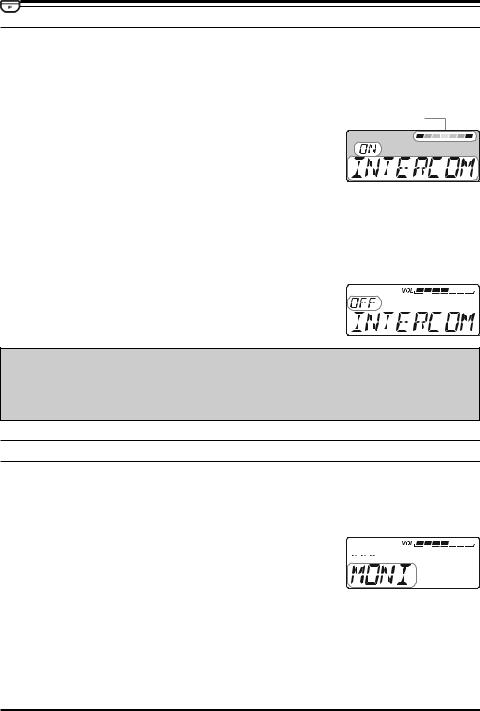
INTERCOM FUNCTION
Intercom operation is possible with the FT-10R, by installing the optional Bluetooth® Adapter unit “BU-1” in the radio and using the optional Bluetooth® Headset “BH-1”. When operating in a very noisy environment, (for example, a loud exhaust or engine noise, or inside an off-road vehicle) communication with a fellow passenger is possible using the Bluetooth® intercom feature.
1. |
Press the top panel |
/ |
key to select “INTERCOM”. |
||
2. |
Press the |
|
key to activate the Intercom function. |
||
|
|||||
When the Intercom function is activated, the volume level graphic will be displayed on LCD.
You may switch the receiver audio volume level between “High” and “Low” via the “VOL.ITCOM” function described below.
When the Intercom function is activated, the internal speakers (front panel and main chassis) are disabled.
To disable the Intercom function, repeat steps 1 and 2 above.
When set the |
|
key function to “INTERCOM” via the |
|
|
|
|
|
||
|
|
|
|
|
|
||||
top panel / |
|
key, the |
|
key to be used as the Inter- |
|
|
|
|
|
|
|
|
|
|
|
|
|||
|
|
|
|
|
|
|
|||
|
|
|
|
|
|
|
|||
com feature on/off key. |
|
|
|
|
|
|
|
||
|
|
|
|
|
|
|
|
|
|
Important Notice!
Use of a sound-isolating headset while driving on public roads is not lawful and hazardous. An open type headset must be used for safety.
MONITOR FEATURE
The Monitor permits disabling the noise and tone squelch systems temporarily.
When the received signal is weak and the sound from the speaker is intermittent, use this function to over-ride the squelch and hear the received signal.
1. |
Press the top panel |
/ |
key to select “MONI”. |
|
|
|
|
|
|
|
|
||||||
|
|
|
|
|
|
|
|
||||||||||
2. |
Press the |
|
|
|
key. |
|
|
|
|
|
|
|
|
|
|
||
|
|
|
|
|
|
|
|
|
|
|
|
||||||
|
|
|
|
|
|
|
|
|
|
|
|
|
|||||
|
|
|
|
|
|
|
|
|
|
|
|
|
|
|
|
||
|
The noise and tone squelch are disabled while pressing the |
|
|
|
|
|
|
|
|
||||||||
|
|
|
key. |
|
|
|
|
|
|
|
|
|
|
|
|
|
|
|
|
|
|
|
|
|
|
|
|
|
|
|
|
|
|
|
|
|
When the |
|
|
|
key function is set to “MONI” via the top panel |
/ |
key, the |
|
key |
||||||||
|
|
|
|
|
|||||||||||||
may be used as the “Monitor” key.
28 |
FTM-10R OPERATING MANUAL |
 Loading...