


C4FM/FM 144/430MHz
DIGITAL/ANALOG TRANSCEIVER
FT-70DR FT-70DE
Operating Manual

Contents |
|
Introduction .............................................................. |
1 |
Quick Guide .............................................................. |
2 |
Controls & Connections .......................................... |
3 |
Transceiver ................................................................ |
3 |
The Keypad Functions .............................................. |
5 |
Display ....................................................................... |
6 |
Safety Precautions (Be Sure to Read) .................... |
8 |
About this manual .................................................. |
11 |
Supplied Accessories and Options ...................... |
11 |
Supplied Accessories .............................................. |
11 |
Available Options .................................................... |
11 |
Preparation ............................................................. |
12 |
Installing the Antenna .............................................. |
12 |
Attaching the Belt Clip ............................................. |
12 |
Installing the Battery Pack ...................................... |
12 |
Removing the Battery Pack .................................... |
12 |
Charging the Battery Pack .................................... |
13 |
Charging the Battery Pack using the Battery Charger .... |
13 |
Charging the Battery Pack using the Rapid Charger (SBH-28) .... |
13 |
External Power Supply .......................................... |
13 |
Connecting an External Power Supply for Use in Vehicle .... |
13 |
Connecting to an External Power Supply Using a Power Cable .... |
13 |
Operation ................................................................ |
14 |
Turning the Transceiver ON .................................... |
14 |
Adjusting the Volume Level ..................................... |
14 |
Adjusting the squelch setting .................................. |
15 |
Selecting a Frequency Band ................................... |
15 |
Tuning to a Frequency ............................................. |
15 |
Changing the Frequency Step ............................. |
15 |
Selecting the Communication Mode ....................... |
16 |
Using AMS (Automatic Mode Select) function ..... |
16 |
Fixing the Communication Mode ......................... |
17 |
Transmission ........................................................... |
17 |
Changing the Transmission Power Level ............... |
18 |
Locking Keys and DIAL knob .................................. |
18 |
Programmable key function .................................... |
18 |
Using the convenient Digital C4FM feature ......... |
19 |
About the Digital Group ID (DG-ID) feature ........... |
19 |
Communicating with the DG-ID feature .................. |
19 |
Setting the transmit and receive DG-ID number to |
|
“00” for communicating with all other stations |
|
using C4FM digital mode ... |
19 |
Communicating only with the specific members |
|
by setting the DG-ID number except for “00” .... |
20 |
About the GM(Group Monitor) feature .................... |
21 |
Displaying the information of the other |
|
station received by GM (Group Monitor) function .... |
22 |
Repeater Operation ................................................ |
23 |
Communicating Via the Repeater ........................... |
23 |
Tone Calling (1750 Hz burst tone) ........................... |
23 |
Using the Memory .................................................. |
24 |
Registering to Memory Channels ........................... |
25 |
Recalling a Memory Channel .................................. |
25 |
Clearing Memories .................................................. |
26 |
Recalling the Home Channels ................................ |
26 |
Changing the Home Channel Frequency ............... |
26 |
Split Memory ........................................................... |
26 |
Using Memory Tag .................................................. |
26 |
Using Memory Bank ................................................ |
26 |
Scanning Function ................................................. |
27 |
VFO Scan ................................................................ |
27 |
Memory Channel Scanning ..................................... |
27 |
Setting the Receive Operation When Scanning Stops .... |
28 |
Weather Alert Scan ................................................. |
28 |
Skip Memory Channel and Specified Memory Channel .... |
29 |
Programmable Memory scan (PMS) ...................... |
29 |
Dual Receive (DW) feature ..................................... |
29 |
Using the WIRES-X Function ................................ |
30 |
WIRES-X feature ..................................................... |
30 |
Connecting to a WIRES-X node |
|
in the C4FM mode (*Recommended) .... |
30 |
Connect and communicate with WIRES-X in analog mode .... |
33 |
Disconnecting from the node or room .................. |
33 |
Convenient Functions ........................................... |
34 |
Tone squelch feature ............................................... |
34 |
Digital Code squelch (DCS) feature ........................ |
34 |
New PAGER (EPCS) feature .................................. |
34 |
Digital Personal ID (DP-ID) feature ........................ |
34 |
Using Set Mode ...................................................... |
35 |
Display and Key Lamp Dimmer ............................... |
35 |
Changing the Beep Volume .................................... |
35 |
Automatic Power OFF (APO) .................................. |
35 |
Time Out Timer (TOT) ............................................. |
35 |
Busy Channel Lock-Out (BCLO) ............................. |
35 |
Receiver Battery Save Function ............................. |
35 |
Password Feature ................................................... |
35 |
Tables of Set Mode Operations .............................. |
36 |
Restoring to Defaults (Reset) ................................ |
38 |
All Reset .............................................................. |
38 |
Set Mode Reset ................................................... |
38 |
Specifications ......................................................... |
39 |

Introduction
Thank you for purchasing this Yaesu product.
ΠP The FT-70DR/FT-70DE is a handheld transceiver for operation in the 144 MHz and 430 MHz Amateur radio bands. It is compatible with the Analog FM and C4FM modes.
ΠP The FT-70DR/FT-70DE is rugged and compact (W60 × H98 × D33 mm (2.36″ × 3.86″ × 1.30″)) providing splash, water, and dust resistant features conforming to IP54 for mobile and field operation.
ΠP The AMS (Automatic Mode Select) feature automatically selects the analog FM and C4FM digital modes, according to the signal of the other station.
ΠP With the GD-ID (Digital Group ID) feature ( 19), the Group Monitor (GM) feature enables automatically locating, and communicating with other stations that have the same DG-ID number within contact range, by utilizing a matching group ID number
from 00 to 99.
ΠP The Digital Personal ID (DP-ID) feature may communicate only by the transceivers registered the individual ID information that is different for each transceiver included
in the transmission radio wave of C4FM digital communication.
ρ Compatible with analog FM mode and C4FM digital modes |
|
|
|
|
16 |
|||
|
|
|
||||||
ρ Equipped with AMS (Automatic Mode Select) Feature |
|
|
|
|
16 |
|||
|
|
|
||||||
ρ The DG-ID function automatically checks to find if there are any stations with |
|
|
|
|
|
|||
the GM function in operation on the same frequency within communication range |
|
|
19 |
|||||
|
||||||||
ρ The DP-ID feature may recall/standby only the other stations that are set with |
|
|
|
|
|
|||
the C4FM Digital transceiver specific number |
|
|
|
|
34 |
|||
|
|
|
||||||
ρ High-brightness LED for easy viewing of the MODE/STATUS indicator |
|
|
4 |
|||||
|
||||||||
ρ Supports Yaesu WIRES-X Internet linking, enabling communication with |
|
|
|
|
|
|||
remote partners via the Internet |
|
|
|
|
30 |
|||
|
|
|
||||||
ρ Dustproof and water-splash-resistant design, equivalent to IPX54, which protects |
|
|
|
|
|
|||
the transceiver from dust and splashes |
|
|
|
|
10 |
|||
|
|
|
||||||
ρ Wide-band reception over the range of 108.000 MHz to 579.995 MHz |
|
|
15 |
|||||
|
||||||||
ρ A wide variety of scan features |
|
|
|
|
27 |
|||
|
|
|
||||||
|
( |
) |
|
|
|
34 |
||
ρ A variety of individual selective calling functions; such as tone squelch CTCSS and DCS functions |
.... |
|
||||||
ρ Large-capacity 999 memory channels |
|
|
|
|
24 |
|||
|
|
|
||||||
ρ 6 home channels and 50 pairs of PMS memory channels |
|
|
26, |
|
29 |
|||
|
|
|
||||||
.......................................ρ Create mnemonic tags for memory channels and Home channel |
|
|
|
|
26 |
|||
.................................................................................ρ Connecting to an external power supply |
|
|
|
|
4 |
|||
( |
) |
|
|
|
|
35 |
||
ρ Automatic power off |
APO feature turns the transceiver OFF after a preset time period....... |
|
|
|||||
ρ Data terminal (Mini USB) for connection to a PC and firmware updates |
|
|
4 |
|||||
|
||||||||
We urge you to read this manual in its entirety, and also the Advance Manual (available for download on the Yaesu website), to gain a full understanding of the amazing capability of the exciting new
FT-70DR/FT-70DE Transceiver.
FT-70DR/FT-70DE Operating Manual |
1 |

Quick Guide
Names and display of Controls
DIAL Knob
Normal operation (VFO Mode)
Operating Frequency
PTT Switch
MONI/T.CALL |
|
|
|
|
|
|
Microphone |
|
|
|
|
|
|
|
|
|
|
|
|
|
|
|
|
|
|
|
|
|
|
|
|
|
|
||
Switch |
|
|
|
|
|
|
[GM] key |
|
|
|
|
|
|
|
|
|
|
VOL Switch |
|
|
|
|
|
|
|
|
|
|
|
|
|
|
|
|
|
Power (Lock) |
|
|
|
|
|
|
[F] key |
|
|
|
|
|
|
|
|
|
|
|
|
|
|
|
|
|
|
|
|
|
|
|
|
|
|
||
Switch |
|
|
|
|
|
|
|
|
|
|
|
|
|
|
|
|
|
[MODE] key |
|
|
|
|
|
|
[BAND] key |
Volume Level |
|
|
|
S Meter / PO Meter |
|||||
|
|
|
|
|
|
|
|
|
|||||||||
|
|
|
|
|
|
|
|
|
|
|
|||||||
|
|
|
|
|
|
|
|
|
|
|
|
|
|
|
|
|
|
Communication Mode
Turning the Power ON
Install the charged battery pack and then press and hold the  switch.
Inputting the Call sign
When turning the power ON for the first time after purchasing, input the call sign of your own station. Input call sign may be changed
from the Set Mode [64 MYCALL]( 37).
37).
1.When turning the power ON for the first time after purchasing, the call sign input screen will be displayed.
2.Press the 
 .
.
Cursol position (digit)
 Cursol
3.Input the call sign.
•Rotate the 


 to select each character.
•Press the 


 key to move the cursor to the right.
4.Repeat step 3 to input the remaining call sign characters.
•Press 


 key to move the cursor to the left.
•Press and hold the 

 key to erase all characters after the cursor.
5.Press the PTT( 
 ) switch to conclude inputting.
Normal operation (VFO Mode) screen will be displayed
Selecting the Operating Band
Press the 


 key.
key.
Tuning the frequency
Rotate the 


 .
.
Adjusting the volume
While pressing and holding the 

 , rotate the


 to adjust the volume to a comfortable level.
Adjusting the squelch setting
The squelch level may be adjusted to mute the background noise when no signal is received.
1.Press the 

 key, and then press the

 key.
key.
2.Rotate the 


 to adjust the squelch to a level at which the background noise is
muted.
* When the squelch level is increased, the noise is more likely to be silenced, but it may become more difficult to receive weak signals.
3. Press the PTT ( 
 ) switch to save the setting.
Selecting the Communication Mode
The communication mode is automatically selected to correspond to the signal being received.
Press the 


 key to manually select the communication mode (
 17).
17).
Transmitting/Receiving Signals
zzTransmitting
While pressing and holding the PTT ( 
 ) switch, speak into the microphone.
zzReceiving
Release the  to return to receive mode.
2 |
FT-70DR/FT-70DE Operating Manual |

|
|
Controls & Connections |
|
Transceiver |
|
|
|
|
|
|
|
|
|
|
|
|
|
|
|
|
|
|
|
|
|
|
|
|
|
|
|
|
|||
|
|
|
|
|
|
|
|
|
|
|
|
|
|
|
|
|
|
|
|
Antenna Jack (SMA)* ( |
12) |
|
|
LCD (Liquid Crystal Display) ( 6)
6)
The display shows the current operating conditions.
PTT Switch ( 17)
17)
•Press and hold the PTT switch to transmit, and release it to receive.
•In the Set mode, press the PTT switch to save the new setting and return to normal operation.
Microphone ( 17)
17)
MONI/T.CALL Switch
USA/Asian version
Press the MONI/T.CALL switch to open the squelch.
European version
Press the MONI/T.CALL switch to activates the T-CALL(1750 Hz). Regarding the current operating mode, both the analog FM and C4FM may monitor the received audio signal.
Press the [F] key → press the MONI/T-CALL switch and then rotate the DIAL knob to adjust the squelch.
VOL Switch ( 14)
14)
While pressing and holding the VOL switch, rotate the DIAL knob to adjust the audio volume level.
Power (Lock) Switch ( 14,
14,  18)
18)
•When the power is OFF, press and hold this switch to turn the Power ON. When the power is ON, press and hold the switch again to turn the Power OFF.
•When the power is ON, press this button briefly to engage, or release the key lock.
Battery pack* ( 12)
12)
FT-70DR/FT-70DE Operating Manual |
3 |

DIAL Knob ( 15)
15)
• Rotate the DIAL Knob to change the frequency or select a memory channel.
• While pressing and holding the VOL Switch, rotate the DIAL knob to adjust the audio volume level.
• Rotate the DIAL Knob to select the desired entry for set mode.
MODE/STATUS Indicator
Indicates the transmit/receive status, and the communication mode with the high brightness LED.
|
Communication status |
Left portion |
Right portion |
|
|
|
Analog FM mode |
|
Green |
Receiving |
|
Digital C4FM mode |
Green |
Blue |
|
Digital Data |
White |
||
|
|
Receiving signals with unmatched DG-ID, |
|
Blink in blue |
|
|
DP-ID, tone frequency or DCS code |
|
|
|
|
|
|
|
Transmitting |
|
Analog FM mode |
Red |
Red |
|
Digital C4FM mode |
Blue |
||
GM function |
|
The other station is within the com- |
|
Light Blue |
|
munication range |
|
||
|
|
|
||
during opera- |
|
Transmitting GM confirmation signal |
|
|
tion |
|
to the other station within the commu- |
|
Blue |
|
|
nication range |
|
|
Speaker
Keypad
The functions of the keypad are described in detail on page 5.
MIC/SP jack*
•Connect a speaker microphone or earpiece microphone to this jack.
•Connect the optional Clone Cable (CT-27), to transfer saved data and function settings to another FT-70DR/DE transceiver.
•Do not connect any microphone which is not specified by Yaesu. A malfunction may can result.
• When an external microphone or cable is connected, the dust and splash protection does not function.
DATA Terminal*
• When updating the firmware, connect to a PC using a USB cable.
* When a new firmware update for the FT-70DR/DE is available, download the data from the YAESU website to update the FT-70DR/DE to the latest version.
* NOTE: the optional camera-equipped microphone (MH-85A11U) is not supported.
EXT DC IN Jack*( 13)
13)
•When charging the battery pack, connect the battery charger to this jack.
•Connect an external power supply adapter with a cigarette lighter plug (SDD-13) or an external power cable (E-DC-6) to this jack.
Strap Hole ( 12)
12)
*: When the included antenna and battery pack are installed and the MIC/SP jack, DATA terminal, and EXT DC IN jack are securely covered with rubber caps, the FT-70DR/DE meets the waterproofing performance conforming to IP54.
4 |
FT-70DR/FT-70DE Operating Manual |

The Keypad Functions
|
|
Primary Function (Press Key) |
Secondary Func- |
Third Function |
|||
Key |
|
|
|
|
tion |
(Press and Hold for |
|
|
VFO or Memory Recall |
Inputting Memory Tag |
(Press F + Key) |
over one second) |
|||
GM |
Turns the GM (Group |
Press and hold this |
|
|
Turns the GM (Group |
||
M onitor) function |
key to erase all char- |
|
M o n i t o r ) f u n c t i o n |
||||
|
ON/OFF |
acters after the cursor |
|
|
ON/OFF |
||
|
Activates the “Sec- |
P r e s s t h i s key t o |
Deactivates the “Sec- |
Enters the Set mode. |
|||
|
ondary” key function |
complete memory tag |
ondary”key function |
||||
|
( |
appears) |
in the Set Mode |
( |
disappears) |
|
|
MODE |
Selects the receive |
Moves the cursor to |
Switches between the |
Sets the DG-ID number |
|||
m o d e b e t w e e n |
frequency display and |
||||||
FM(AM), DN and VW* |
the left. |
the memory tag display |
|
||||
HM/ |
Reverses the transmit |
|
Recalls the “HOME” |
Overwrites the “HOME” |
|||
and receive frequen- |
|
||||||
(favorite frequency) |
(favorite frequency) |
||||||
RV |
cies while working |
|
channel |
channel |
|||
|
through a repeater |
|
|||||
|
|
|
|
|
|||
AMS |
Selects AMS Mode (TX |
|
A c t i v a t e s t h e |
Activates the A MS |
|||
AUT/TX FM/TX DIG) |
WIRES-X feature |
feature |
|||||
BAND |
Moves operation to |
Moves the cursor to |
Moves operation to |
|
|||
the next-highest fre- |
the next-lowest fre- |
||||||
(BND DN) |
quency band |
the right |
quency band |
|
|||
V/M |
Switches between the |
Press and hold this key |
Enables the Dual Re- |
Activates the “Memory |
|||
(DW) |
VFO mode and the |
to complete the memo- |
ceive function |
Write” mode (for mem- |
|||
|
Memory Channel mode |
ry channel registration |
|
|
ory channel storage) |
||
1 |
|
|
|
Selects the desired |
Enters all the zeros at once |
||
Number “1” |
Number “1” |
transmit power output |
after entering the number “1” |
||||
(TX PO) |
|||||||
|
|
|
level. |
on inputting the frequency. |
|||
2 |
Number “2” |
Number “2”, or char- |
|
|
Enters all the zeros at once |
||
Starts the scanning |
after entering the number “2” |
||||||
(SCAN) |
|
|
acters “A”, “B”, or “C” |
|
|
on inputting the frequency. |
|
|
|
|
|
|
|
||
3 |
Number “3” |
Number “3”, or char- |
|
|
Enters all the zeros at once |
||
Selects the DTMF mode. |
after entering the number “3” |
||||||
(DTMF) |
|
|
acters “D”, “E”, or “F” |
|
|
on inputting the frequency. |
|
|
|
|
|
|
|
||
4 |
Number “4” |
Number “4”, charac- |
Selects the frequency |
Enters all the zeros at once |
|||
after entering the number “4” |
|||||||
(STEP) |
|
|
ters “G”, “H”, or “I” |
steps |
on inputting the frequency. |
||
|
|
|
|
|
|
||
5 |
Number “5” |
Number “5”, charac- |
Selects the squelch |
Enters all the zeros at once |
|||
(SQ TYP) |
ters “J”, “K”, or “L” |
types |
after entering the number “5” |
||||
|
|
|
|
|
|
on inputting the frequency. |
|
6 |
Number “6” |
Number “6”, or char- |
Selects the CTCSS |
enters all the zeros at once |
|||
after entering the number “6” |
|||||||
(CODE) |
|
|
acters “M”, “N”,or “O” |
Tone or DCS code |
on inputting the frequency. |
||
|
|
|
|
|
|
||
7 |
Number “7” |
Number “7”, or char- |
P1 |
(programmable |
enters all the zeros at once |
||
acters “P”, “Q”, “R”, or |
|
) |
after entering the number “7” |
||||
(P1) |
|
|
“S” |
key 1 |
on inputting the frequency. |
||
|
|
|
|
|
|||
8 |
Number “8” |
Number “8”, or char- |
P2 |
(programmable |
enters all the zeros at once |
||
acters “T”, “U”, or “V” |
|
) |
after entering the number “8” |
||||
(P2) |
|
|
key 2 |
on inputting the frequency. |
|||
|
|
|
|
|
|
||
9 |
|
|
Number “9”, or char- |
Selects the Memory |
enters all the zeros at once |
||
Number “9” |
acters “W”, “X”, “Y”, |
Scan “Skip” channel |
after entering the number “9” |
||||
(SKIP) |
|
|
or “Z” |
or “Select” channel |
on inputting the frequency. |
||
|
|
|
|||||
0 |
|
|
Number “0”, or sym- |
Selects the direction of |
enters all the zeros at once |
||
Number “0” |
bols“(space)”, “-”, “/”, |
the up link frequency shift |
after entering the number “0” |
||||
( |
) |
||||||
(RPT) |
|
|
“?”, or “!” |
either “–”, “+”, or “simplex” |
on inputting the frequency. |
||
|
|
|
|
during repeater operation. |
|
||
*: VW icon is displayed when Set Mode [16 DIG VW] ( 36) is set to “ON” (the default setting is “OFF”).
FT-70DR/FT-70DE Operating Manual |
5 |
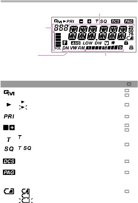
Display
Frequency / Memory Tag /
Set Mode Item
Memory Channel Number / HOME Channel /
Memory Bank Number/
In Range / Out of Range (GM function)
Volume Bar Graph 
Communication Mode DN: Normal digital mode VW: Voice wide mode FM: Analog FM mode
AM: AM mode (Receive only)
S Meter Displays the received signal strength PO Meter Displays the transmit power level
|
Icon |
|
|
|
|
|
|
Description |
|
|
|
|
|
|
|
|
|
||||||||||
|
|
|
|
|
|
|
|
|
|
|
|
|
|
|
|
|
|
Appears when the GM (Group Monitor) function in the digital |
|
|
19 |
||||||
|
|
|
|
||||||||||
|
|
|
|
mode is enabled. |
|
|
22 |
||||||
|
|
|
|
||||||||||
|
|
|
|
|
|
|
|
|
|
|
|
|
|
|
|
|
|
|
|
|
׃ Memory channel registered as a skip memory |
|
|
29 |
|||
|
|
|
|
|
|
|
׃ Memory channel registered as a specified memory (with blink) |
|
|
||||
|
|
|
|
|
|
|
|
||||||
|
|
|
|
|
|
|
|
|
|
|
|||
|
|
|
|
|
|
|
|
|
|
|
|
|
|
|
|
|
|
Priority Memory Channel |
|
|
29 |
||||||
|
|
|
|
||||||||||
|
|
|
|
|
|
|
|
|
|
|
|
|
|
|
|
|
|
Repeater Shift Direction |
|
|
23 |
||||||
|
|
|
|
||||||||||
|
|
|
|
Split Memory (a simultaneously) |
|
|
26 |
||||||
|
|
|
|||||||||||
|
|
|
|
||||||||||
|
|
|
|
|
|
|
|
|
|
|
|
|
|
|
|
|
|
|
|
|
|
|
׃ Appears when the tone encoder function in the ana- |
|
|
|
|
|
|
|
|
|
|
|
|
|
log FM mode is enabled. |
|
|
34 |
|
|
|
|
|
|
|
|
|
|
׃ Appears when the tone squelch function in the ana- |
|
|
||
|
|
|
|
|
|
|
|
|
|
|
|
|
|
|
|
|
|
|
|
|
|
|
log FM mode is enabled. |
|
|
|
|
|
|
|
|
|
|
|
|
|
|
|
|
|
|
|
|
|
|
Appears when the DCS function in the analog FM mode is enabled. |
|
|
34 |
||||||
|
|
|
|
||||||||||
|
|
|
|
|
|
|
|
|
|
|
|
|
|
|
|
|
|
Appears when the PAGER function is enabled. |
|
|
34 |
||||||
|
|
|
|
||||||||||
|
|
|
|
|
|
|
|
|
|
|
|
|
|
|
|
|
|
The battery condition is displayed in 4 steps. |
|
|
|
|
|||||
|
|
|
|
(No display) ׃ Full battery power |
|
|
|
|
|||||
|
|
|
|
|
|
|
|
|
׃ Enough battery power |
|
|
13 |
|
|
|
|
|
|
|
|
|
|
|
||||
|
|
|
|
|
|
|
|
|
׃ Battery is depleted. Charge battery. |
|
|
|
|
|
|
|
|
|
|
|
|
|
׃ (When blinking) Charge battery immediately. |
|
|
|
|
|
|
|
|
|
|
|
|
|
|
|
|
||
|
|
|
|
|
|
|
|
|
|
|
|
|
|
|
|
|
|
|
|
|
|
|
|
|
|
|
|
6 |
FT-70DR/FT-70DE Operating Manual |

Icon |
|
|
|
|
|
|
|
|
|
Description |
|
|
|
|
|
|
||
|
|
|
|
|
|
|
|
|
|
|
|
|
|
|
||||
|
|
|
|
|
|
|
|
|
|
|
|
|
|
|
|
|
|
|
|
|
|
|
|
|
: Appears when a function key is pressed. |
|
|
|
|
5 |
|||||||
|
|
|
|
|
|
|
|
|||||||||||
|
|
|
|
|
|
: On writing the memory channel, etc. |
|
|
|
|
25 |
|||||||
|
|
|
|
|
|
|
|
|||||||||||
|
|
|
|
|
||||||||||||||
|
|
|
|
|
|
|
|
|
|
|
|
|
|
|
|
|
|
|
|
Appears when the AMS (Automatic Mode Select) function is en- |
|
|
|
|
|
|
|||||||||||
|
abled. It is recommended that AMS function be enabled for nor- |
|
|
16 |
||||||||||||||
|
|
|||||||||||||||||
|
mal operations. |
|
|
|
|
|
|
|
|
|
|
|||||||
|
TX Power Level Indicator (LOW/MID TX Power Selected) |
|
|
|
|
|
|
|||||||||||
|
|
|
|
|
|
|
|
|
|
|
|
|
|
|
||||
|
|
|
|
Tx Power |
|
Icon |
|
TX Power Meter during transmission |
|
|
|
|
|
|
|
|||
|
|
( |
) |
|
( |
) |
|
|
|
|
|
18 |
||||||
|
|
|
|
|
|
|
|
|||||||||||
|
|
|
HIGH 5 W |
|
|
No display |
|
|
|
|
||||||||
|
|
|
|
|
|
|
|
|
|
|
|
|
|
|
|
|
|
|
|
|
|
MID (2 W) |
|
|
|
|
|
|
|
|
|
|
|
|
|||
|
|
|
LOW (0.5 W) |
|
|
|
|
|
|
|
|
|
|
|
||||
|
|
|
|
|
|
|
|
|
|
|
|
|
|
|
|
|
|
|
|
Appears when the Dual Receive(DW) function is enabled. |
|
|
29 |
||||||||||||||
|
|
|||||||||||||||||
|
|
|
|
|
|
|
|
|
|
|
|
|
|
|
|
|
|
|
|
Appears when the APO (Automatic Power-Off) function is enabled. |
|
|
35 |
||||||||||||||
|
|
|||||||||||||||||
|
|
|
|
|
|
|
|
|
|
|
|
|
|
|
|
|
|
|
|
Appears when the bell function in the analog FM mode is enabled. |
|
|
36 |
||||||||||||||
|
|
|||||||||||||||||
|
|
|
|
|
|
|
|
|
|
|
|
|
|
|
|
|
|
|
|
Appears when the lock function is enabled. |
|
|
18 |
||||||||||||||
|
|
|||||||||||||||||
|
|
|
|
|
|
|
|
|
|
|
|
|
|
|
|
|
|
|
|
V/D mode (Normal digital mode) |
|
|
17 |
||||||||||||||
|
|
|||||||||||||||||
|
|
|
|
|
|
|
|
|
|
|
|
|
|
|
|
|
|
|
|
Voice FR mode (Voice wide mode) |
|
|
17 |
||||||||||||||
|
|
|||||||||||||||||
|
|
|
|
|
|
|
|
|
|
|
|
|
|
|
|
|
|
|
|
Analog FM mode |
|
|
|
|
|
17 |
|||||||||||
|
|
|
|
|
||||||||||||||
|
|
|
|
|
|
|
|
|
|
|
|
|
|
|
|
|
|
|
|
AM mode (Receive only) |
|
|
|
|
|
17 |
|||||||||||
|
|
|
|
|
||||||||||||||
|
|
|
|
|
|
|
|
|
|
|
|
|
|
|
|
|
|
|
|
DTMF Autodialer Active |
|
|
|
|
|
|
|
– |
|||||||||
|
|
|
|
|
|
|
|
|
|
|
|
|
|
|
|
|
|
|
FT-70DR/FT-70DE Operating Manual |
7 |

Safety Precautions (Be Sure to Read)
Be sure to read these important precautions, and use this product safely.
Yaesu is not liable for any failures or problems caused by the use or misuse of this product by the pur-
chaser or any third party. Also, Yaesu is not liable for damages caused through the use of this product by the purchaser or any third party, except in cases where ordered to pay damages under the laws.
Types and meanings of the marks
DANGER |
This mark indicates an imminently hazardous situation, which, if not |
|
avoided, could result in death or serious injury. |
||
|
||
WARNING |
This mark indicates a potentially hazardous situation, which, if not |
|
|
avoided, could result in death or serious injury. |
|
CAUTION |
This mark indicates a potentially hazardous situation, which, if not avoid- |
|
|
ed, may result in minor or moderate injury or only property damage. |
Types and meanings of symbols
These symbols signify prohibited actions, which must not be done to use this product safely. For example:  indicates that the product should not be disassembled.
These symbols signify required actions, which must be done to use this product safely. For example,:  indicates that the power plug should be disconnected.
 DANGER
Do not use this product in an area where RF transmitters are prohibited, e.g., inside of a hospital, airplane, or train.
This product can affect electronic or medical devices.
Do not use this product or the battery charger anywhere inflammable gas is produced.
A fire or explosion can occur.
Do not transmit with this device while carrying or using a medical appliance such as a cardiac pacemaker. When transmitting, use an external antenna and keep as far as possible away from the external antenna.
The radio wave emitted by the transmitter can cause the medical device to malfunction and result in injury or death.
Do not transmit with this device in a crowded place for the safety of persons using a medical device such as a cardiac pacemaker.
The radio wave emitted from this product can cause the medical device to malfunction and result in injury or death.
If thunder and lightening develop nearby when an external antenna is used, immediately turn this transceiver OFF, and disconnect the external antenna from it.
A fire, electrical shock, or damage may result.
Do not use this product while riding a bicycle or driving a car. Accidents can result.
Be sure to stop the bicycle or car at a safe place before using this product.
Do not touch any material leaking from the LCD display or the battery pack with bare hands.
The chemical may adhere to your skin or enter your eye, and cause chemical burns. In such a case, consult the doctor immediately.
Do not solder or short-circuit the terminals of the battery pack.
A fire, leak, overheating, explosion, or ignition may result.
Do not carry the battery pack together with a necklace, hairpin, or small metal objects. A short circuit can result.
 WARNING
Do not disassemble or make any alteration to this product.
An injury, electric shock, or failure may result.
Do not handle the battery pack or charger with wet hands. Do not insert or remove the power plug with wet hands.
An injury, leak, fire, or failure may result.
Keep the terminals of the battery pack clean.
If terminal contacts are dirty or corroded, a fire, leak, overheating, explosion, or ignition can result.
8 |
FT-70DR/FT-70DE Operating Manual |
If smoke or a strange odor is emitted from the main body, battery pack, or battery charger, immediately turn the transceiver off; remove the battery pack, and remove the power plug from the outlet.
A fire, chemical leak, overheating, component damage, ignition, or failure may result. Contact the dealer from which you purchased this product or Yaesu Amateur Customer Support.
Do not bend, twist, pull, heat and modify the power cord and connection cables in an unreasonable manner.
This may cut or damage the cables and result in fire, electric shock and equipment failure.
Do not pull the cable when plugging and unplugging the power cord and connection cables.
Always hold the plug or connector when unplugging; if not, a fire, electric shock and equipment failure may result.
Do not use the device when the power cord and connection cables are damaged, or when the DC power connector cannot be plugged in tightly.
Contact Yaesu Amateur Customer Support or the retail store where this transceiver was purchased for assistance, as this may result in fire, electric shock and equipment failure.
Never cut the fuse holder off of the DC power cord.
This may cause a short circuit and result in ignition and fire.
Use only the specified type fuses.
Use of an incorrect fuse may result in fire and equipment failure.
Do not install the front panel, the transceiver or the wire cables near the automobile air bags.
In case of an accident, the transceiver may interfere with air bag deployment and result in extreme injury. The wire cables may also cause the air bag to malfunction.
Do not power this transceiver with a voltage other than the specified power supply voltage.
A fire, electric shock, or damage may result.
Do not make very long transmissions.
The main body of the transceiver may overheat, resulting component failure or operator burns.
Do not place the transceiver in wet or damp areas (e.g. near a humidifier).
This may result in fire, electric shock and equipment failure.
Do not use DC power cords other than the one enclosed or specified.
This may result in fire, electric shock and equipment malfunctions.
When connecting a DC power cord, be certain the positive and negative polarities are correct.
Reverse connection will result in equipment damage.
When transmitting, keep the transceiver at least 5.0 mm (3/16 inch) away from your body. Use only the supplied antenna. Do not use modified or damaged antennas.
Disconnect the power cord and connection cables before installing separately sold accessory items, or replacing the fuse.
This may result in fire, electric shock and equipment failure.
Follow the instructions provided when installing items sold separately and replacing the fuse.
This may result in fire, electric shock and equipment failure.
Use only the provided or specified screws.
Using screws of a different size, may result in fire, electric shock and component damage.
Do not place the transceiver in a confined space, such as a bookshelf which is not ventilated well.
This may result in overheating and fire, electric shock and equipment failure.
Do not operate the transceiver on a carpet or a blanket.
This may result in overheating and fire, electric shock and equipment failure.
If a foreign substance is spilled into the transceiver, turn it OFF immediately and remove the power plug from the outlet.
If used as it is, a fire, electrical shock, or damage may result.
 CAUTION
Do not place the transceiver on an unsteady or sloping surface, or in a location with extreme vibration.
The transceiver may fall or drop, resulting in fire, injury and equipment damage.
Do not place this transceiver in a humid or dusty place.
A fire or failure may result.
Do not use the transceiver near the radio relay equipment.
Transmissions may affect radio communication.
Do not wipe the case using thinner and benzene etc.
Use only a soft, dry cloth to wipe stains from the case.
Do not throw the transceiver, or subject it to strong impact forces.
Physical abuse may result in component damage and equipment failure.
If the transceiver will not be used for an extended period, turn it OFF and remove the battery pack for safety.
FT-70DR/FT-70DE Operating Manual |
9 |

Keep magnetic cards and videotapes away from the transceiver.
The data recorded on cash cards or videotapes may be erased.
Do not place this transceiver in direct sunlight or near a heater.
The case may be deformed or discolored.
Be sure to check with the manufacturer of any hybrid or fuel-saving automobile regarding use of the transceiver in that car.
Noise generated by an onboard electrical device (inverter, etc.) can disrupt the normal operation of the transceiver.
Do not operate the transceiver near the TV or radio.
Radio disturbance can occur in the transceiver, the TV, or the radio.
Do not transmit near the television and radio.
Transmissions may cause electromagnetic interference.
While transmitting, keep the antenna as far from you as possible.
Long-time exposure to electromagnetic waves may have a negative impact on your health.
Do not dangle or throw the transceiver by holding its antenna.
This may injure others and may also result in damage and failure of the transceiver.
Do not use the transceiver in a crowded place.
The antenna may strike others and result in an injury.
Keep this product out of the reach of children.
Injury to the child, or damage to the transceiver may result.
Do not use any products other than the specified options and accessories.
Failure or miss operation may result.
Install the hand strap and belt clip securely.
Improper installation may cause the FT70DR/ FT-70DE to fall or drop, resulting in an injury or damage.
This product has a waterproof structure and conforms to “IP54” when the included antenna and battery pack are installed and rubber caps are securely attached to the MIC/SP jack, EXT DC IN jack, and DATA terminal. If this transceiver gets wet, dry it with a soft cloth, do not leave it exposed to the moisture.
Exposure to excessive moisture may degrade the transceiver performance, shorten its life, or cause a failure or electrical shock.
Before discarding a depleted battery pack, affix tape or insulating covering to its terminals.
About Splash, Water, and Dust Resistant Features Conforming to IP54
When the included antenna and battery pack are installed, and the MIC/SP jack, EXT DC IN jack and DATA terminal are securely covered with rubber caps, this product is dust and splash resistant. To ensure continued Splash, Water, and Dust Resistant Features be sure to check the following points before each use.
ρCheck for damages, deterioration, and dirt.
Antenna rubber, key switch rubber, MIC/SP jack, EXT DC IN jack, DATA terminal rubber cap, and battery pack seals.
ρCleaning
Wipe with a dry soft cloth.
When this product is contaminated with seawater, sand or dirt, clean it with a soft damp cloth immediately.
ρRecommended maintenance interval
To insure continued optimal performance, it is recommended that maintenance be performed annually, or when any damage or deterioration is found.
Note that the maintenance service is subject to fees.
ρDo not pour or immerse this product in the following liquids:
Sea, pool, hot spring, water containing soap, detergent, or bath additive, alcohol, or chemicals.
ρDo not leave this product for an extended time in a very humid location:
Bathroom, kitchen, or humid place.
ρOther precautions
Do not remove the rubber cap from the battery pack, the MIC/SP jack, the EXT DC IN jack, or the DATA terminal when water drops have accumulated on the transceiver, or when it is placed in a wet environment. This may result in water penetrating the transceiver, and causing equipment failure.
This product is not totally waterproof, and must never be immersed in water.
10 |
FT-70DR/FT-70DE Operating Manual |

About this manual
Reference icon symbols and conventions are used in this manual. Their meanings are described in the below chart.
Symbols |
Description |
This icon indicates cautions and information that should be read.
This icon indicates notes, tips and information that should be read.
This icon indicates other pages containing relevant information.
This icon indicates FT-70DR/DE Advance Manual on the YAESU Website containing relevant information.
•The settings at the time of purchase are referred to as the “default” or “default settings”.
•The names of Set Mode items displayed in the LCD, and the key names of the transceiver appear in bold characters.
Supplied Accessories and Options
Supplied Accessories
ρ 7.4 V, 1800 mAh Rechargeable Li-Ion Battery Pack |
SBR-24LI |
|
|
ρ Battery Charger |
|
SAD-18B*1 |
|
|
|
SAD-11C/F/U*2 |
|
ρ Antenna |
ρ Operating Manual (this manual) |
ρ Warranty Card |
|
ρ Belt Clip |
ρ USB cable |
|
ρ SBR-24LI Manual |
zz Ensure that the name of the dealer from which the transceiver was purchased, and the date of purchase are indicated on the warranty card.
zz If any item is missing, contact the dealer from which the transceiver was purchased.
Available Options
ρ 7.4 V, 1800 mAh Rechargeable Li-Ion Battery Pack |
SBR-24LI |
|
||
ρ Battery Charger |
|
|
SAD-18B*1 |
|
|
|
|
SAD-11C/F/U*2 |
|
ρ Rapid Charger |
|
|
SBH-28 |
|
ρ DC Cable with and Cigarette-Lighter Plug |
SDD-13 |
|
||
ρ DC Cable |
|
MH-34B4B |
E-DC-6 |
SSM-57A |
ρ Speaker / Microphone |
|
ρ Earpiece Microphone |
||
ρ VOX Headset |
|
SSM-63A |
ρ Microphone Adapter |
CT-44 |
( |
) |
CN-3 |
ρ Soft Case |
SHC-27 |
ρ BNC-to-SMAAdapter BNCJ-SMAP |
||||
ρ Cloning Cable |
|
CT-27 |
|
|
*1 USA Version
*2 “B” suffix is for use with 120 VAC (Type-A plug), “C” suffix is for use with 230-240 VAC (Type-C plug), “F” suffix is for use with 220 VAC, “H” suffix is for use with 220-230 VAC (Australian plug), and “U” suffix is for use with 230 VAC (Type-BF plug).
Availability of accessories may vary. Some accessories are supplied as standard to meet local requirements, while others may be unavailable in some regions. Consult your Yaesu Dealer for details regarding these and any newly-available options. Connection of any accessory not approved by Yaesu, should it cause damage, may void the Limited Warranty on this apparatus.
FT-70DR/FT-70DE Operating Manual |
11 |
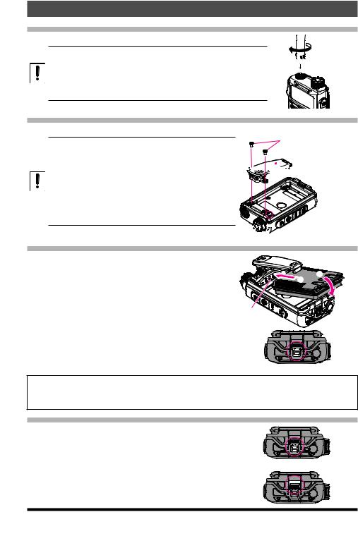
Preparation
Installing the Antenna
1. Turn the antenna clockwise until it is secured.
zz Do not hold or twist the upper part of the antenna when installing or removing it. To do so may break the conductors inside the antenna.
zz Do not key the transmit without installing the antenna. The transmitter components may be damaged.
zz When using an antenna other than the one supplied, or connecting to an external antenna, ensure that the SWR is adjusted to 1.5 or lower.
 Hold the thick base of the antenna
Attaching the Belt Clip
1. Attach the belt clip on the back of transceiver using the supplied screws (two).
zz Be sure to use the supplied screws when attaching the belt clip. If any other screws are used, the belt clip cannot be secured firmly to the battery pack and the transceiver may drop off together with the battery pack; the transceiver and battery pack may fall off, causing injury, breakage and other damage.
zz Use a hand strap which can withstand the weight of the transceiver. If the hand strap is not strong enough, the it may break and the transceiver may fall, causing injury, breakage and other difficulty.
Supplied Screws


 Belt Clip


 Strap Hole for commercially


 available strap
Installing the Battery Pack
1.Lift the belt clip outward ( ) and Insert the battery pack into the seals of the battery compartment on the back of the transceiver.
2.Push the battery pack in until the battery latch clicks securely ().
3.Slide the battery pack lock plate to the “UNLOCK” position beside the battery latch until the entire “LOCK” appears.
|
|
|
Battery pack 


 connect


Lock
Caution
Risk of explosion if battery is replaced by an incorrect typ. Dispose of used batteries according to the instructions.
Removing the Battery Pack
1. Slide the battery pack lock plate to the “UNLOCK” position.
Unlock
2. Push the release button (PUSH) and tilt the Belt Clip outward, and then remove the battery pack.
12 |
FT-70DR/FT-70DE Operating Manual |
 Loading...