


 Loading...
FT-891
Advance Manual
HF/50 MHz TRANSCEIVER

Contents |
|
CW Mode Operation.................................................. |
3 |
Setup for Straight Key |
|
(and Straight Key Emulation) Operation.... |
3 |
Using the Built-in Electronic Keyer........................... |
4 |
Adjusting the keyer speed........................................ |
5 |
Full Break-in (QSK) Operation................................. |
5 |
Setting the Keyer Weight (Dot/Dash) Ratio.............. |
6 |
Reversing the Keyer Polarity.................................... |
6 |
Selecting the Keyer Operating Mode....................... |
7 |
CW Delay Time Setting............................................ |
8 |
CW Pitch Adjustment............................................... |
8 |
CW Spotting (Zero-Beating)..................................... |
9 |
Using the Auto Zeroing System............................. |
9 |
Using the SPOT System....................................... |
9 |
Audio Peak Filter.................................................... |
10 |
Contest Memory Keyer........................................... |
11 |
Message Memory................................................. |
11 |
Text Memory........................................................ |
17 |
Contest Number Programming............................ |
23 |
Decrementing the Contest Number..................... |
23 |
Transmitting in the Beacon Mode........................ |
24 |
FM Mode Operation................................................. |
25 |
Basic Operation...................................................... |
25 |
Repeater Operation................................................ |
26 |
Tone Squelch Operation......................................... |
27 |
DCS Operation....................................................... |
28 |
Interference Rejection............................................ |
29 |
CONTOUR Control Operation................................ |
29 |
WIDTH (IF DSP Bandwidth) Tuning |
|
(SSB/CW/RTTY/DATA Modes)..... |
30 |
Using IF SHIFT and WIDTH Together................. |
31 |
NARROW (NAR) One-Touch IF Filter Selection.... |
31 |
IF NOTCH Filter Operation |
|
(SSB/CW/RTTY/DATA/AM Modes)..... |
32 |
Digital Noise Reduction (DNR) Operation.............. |
33 |
Digital NOTCH Filter (DNF) Operation................... |
34 |
Tools for Comfortable and Effective Reception... |
35 |
RF Gain (SSB/CW/AM Modes).............................. |
35 |
ATT (Attenuator)..................................................... |
35 |
IPO (Intercept Point Optimization)......................... |
36 |
AGC (Automatic Gain Control)............................... |
36 |
Adjustable Receiver Audio Filter............................ |
37 |
Enhancing Transmit Signal Quality....................... |
38 |
Mic Gain................................................................. |
38 |
Speech Processor (SSB Mode)............................. |
38 |
Parametric Microphone Equalizer |
|
(SSB/AM mode).... |
39 |
Setup of the Parametric Microphone Equalizer.... |
39 |
Activating the Parametric Microphone Equalizer.... |
40 |
Adjusting the SSB Transmitted Bandwidth |
|
(SSB Mode)..... |
41 |
Transmitter Convenience Features....................... |
42 |
Voice Memory (SSB/AM modes)............................ |
42 |
Voice Memory Operation..................................... |
42 |
VOX (SSB/AM/FM Modes: Automatic |
|
TX/RX Switching using Voice Control)..... |
46 |
MONITOR (SSB/CW/AM modes)........................... |
47 |
Split Operation Using the TX Clarifier.................... |
48 |
Split-Frequency Operation..................................... |
49 |
Quick Split Operation.......................................... |
50 |
Memory Operation.................................................. |
51 |
Checking a Memory Channel Status...................... |
51 |
Memory Tune (MT) operation................................. |
51 |
Labeling Memories................................................. |
52 |
Displaying the memory tag ................................. |
52 |
Memory Groups..................................................... |
53 |
Memory Group Assignment................................. |
53 |
Choosing the Desired Memory Group................. |
54 |
Operation on Alaska Emergency Frequency: |
|
5167.5 kHz (U.S. Version Only).... |
55 |
Scanning Operation................................................ |
56 |
Scan Resume Options........................................... |
56 |
PMS (Programmable Memory Scanning).............. |
57 |
Miscellaneous Setting............................................ |
58 |
Beep Level............................................................. |
58 |
TOT (Time-Out Timer)............................................ |
58 |
APO (Automatic Power Off)................................... |
59 |
FAN Control............................................................ |
59 |
Meter Peak Hold.................................................... |
60 |
POP-UP Menu....................................................... |
60 |
Key Lamp Dimmer................................................. |
61 |
TX/BUSY Indicator Dimmer................................... |
61 |
RTTY (Radio Teletype) Operation.......................... |
62 |
Example of Connecting RTTY |
|
Communications device..... |
62 |
Connecting to the TU (Terminal Unit).................. |
62 |
Connecting to your Computer............................. |
63 |
DATA (PSK) Operation............................................ |
64 |
Example of DATA Communications device............ |
64 |
DATA-AFSK (PSK, OLIVIA, |
|
CONTESTIA, RTTY etc.).... |
65 |
DATA MODE (PSK, OLIVIA, |
|
CONTESTIA, RTTY etc.).... |
67 |
Menu Mode.............................................................. |
69 |
Optional FH-2 Remote Control Switches............ |
102 |
Optional MH-36E8J Microphone Switches......... |
103 |
FC-50 External Automatic Antenna Tuner.......... |
104 |
Interconnections to FT-891.................................. |
104 |
Setup the FT-891................................................. |
104 |
Operation............................................................. |
105 |
FC-40 External Automatic Antenna Tuner |
|
(for Wire Antenna)..... |
106 |
Interconnections to FT-891.................................. |
106 |
Setup the FT-891................................................. |
107 |
Operation............................................................. |
107 |
Auto Active-Tuning Antenna System |
|
(ATAS-120A) Operation..... 108 |
|
Interconnections to FT-891.................................. |
108 |
Setup the FT-891................................................. |
109 |
Tuning Operation.................................................. |
109 |
Manual Tuning....................................................... |
110 |
VL-1000 Linear Amplifier Interconnections......... |
111 |
Index....................................................................... |
112 |
2 |
FT-891 Advance Manual |
CW Mode Operation
The powerful CW operating capabilities of the FT-891 permit operation using an electronic keyer paddle, a “straight key”, or a computer-based keying device.
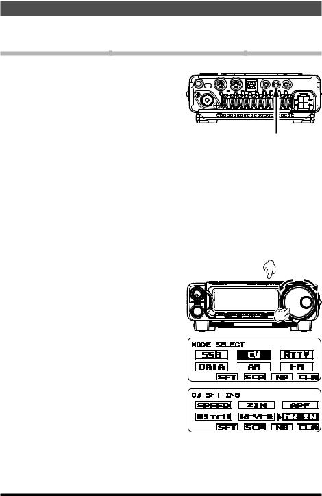
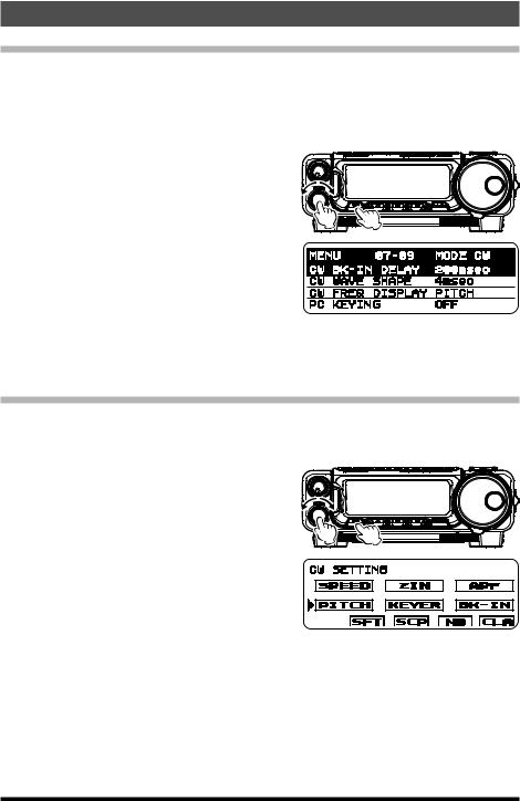
Setup for Straight Key (and Straight Key Emulation) Operation
Before starting, connect a key line to the rear panel KEY jack.
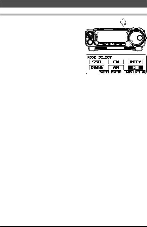
1.Press and hold the [BAND(MODE)] key for one second.
The “MODE SELECT” screen will appear in the display.
2.Rotate the DIAL knob to select the “CW” mode.
3.Press the [F] key repeatedly to find the “CW SETTING” list screen.
4.Rotate the MULTI function knob to select “BK-IN”.
5.Press the MULTI function knob to engage the “break-in” system.
6.Press and hold the [F] key for one second to exit the “CW SETTING” list screen and resume normal operation.
7.When the key is pressed, the transmitter will automatically be engaged.
8.When the key is released, the receiver audio will return, after a brief delay.
ρThe CW sidetone audio level may be adjusted by setting “MONITOR” (see page 47).
ρTo enable the keying operation in LSB/ USB mode and send the CW signal without
switching to CW mode, change Menu item “07-06 [CW AUTO MODE]”.
ρThe same frequency may be displayed when switching between SSB mode and CW mode by setting Menu item “07-01
[CW FREQ DISPLAY]”.
ρBy connecting the FT-891 to a computer, CW can be operated using free or commercially
available software and setting Menu item “07-12 [PC KEYING]”.
KEY Jack
KEY GND
KEY NC GND
3 |
FT-891 Advance Manual |

CW Mode Operation
Using the Built-in Electronic Keyer
Before starting, connect the cable from your keyer paddle to the rear panel KEY jack.
1.Press and hold the [BAND(MODE)] key for one second.
The “MODE SELECT” screen will appear in the display.
2.Rotate the DIAL knob to select the “CW” mode.
3.Press the [F] key repeatedly to find the “CW SETTING” list screen.
4.Rotate the MULTI function knob to select “BK-IN”.
5.Press the MULTI function knob to engage the “break-in” system.
6.Rotate the MULTI function knob to select “KEYER”.
7.Press the MULTI function knob to engage the built-in Electronic Keyer.
8.Press and hold the [F] key for one second to exit the “CW SETTING” list screen and resume normal operation.
9.When the keyer paddle is pressed, the transmitter will automatically be engaged.
10.When the paddle is released, the receiver audio will return, after a brief delay.
ρThe CW sidetone audio level may be adjusted by setting “MONITOR” (see page 47).
ρTo enable the keying operation in LSB/ USB mode and send the CW signal without
switching to CW mode, change Menu item “07-06 [CW AUTO MODE]”.
ρThe same frequency may be displayed when switching between SSB mode and CW mode by setting Menu item “07-01
[CW FREQ DISPLAY]”.
ρBy connecting the FT-891 to a computer, CW can be operated using free or commercially
available software and setting Menu item “07-12 [PC KEYING]”.
KEY Jack
DOT DASH COMMON
DOT DASH COMMON
4 |
FT-891 Advance Manual |
CW Mode Operation
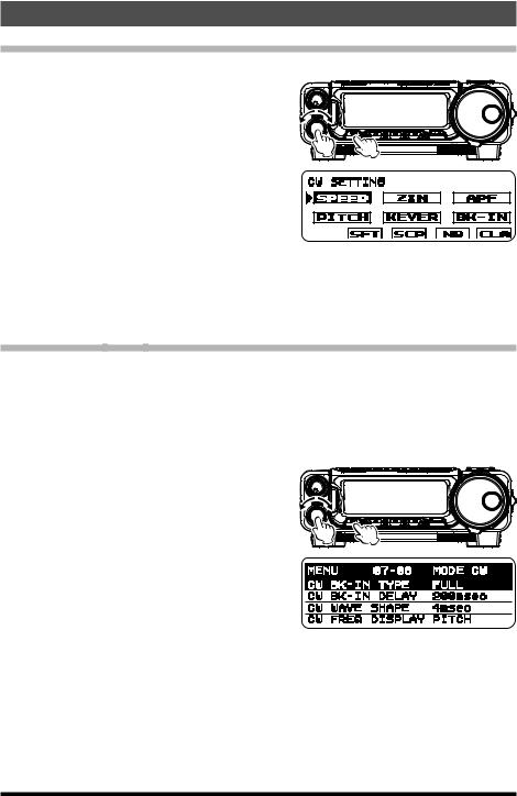
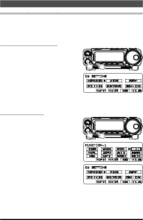
Adjusting the keyer speed
The keyer speed can be adjusted via the “CW SETTING” list screen.
1. Press the [F] key repeatedly to find the “CW SETTING” list screen. 2. Rotate the MULTI function knob to select
“SPEED”. 3. Press the MULTI function knob, the keying
speed pop-up screen will appear.
4. Rotate the MULTI function knob to set the desired sending speed (4 - 60 WPM).
Default: 20 WPM
5.Press the MULTI function knob, then press and hold the [F] key for one second to exit the “CW SETTING” list screen and resume normal operation.
ρKeyer speed function may be assigned to the [A], [B] or [C] key. Refer to “Changing the function assigned to the [A]/[B]/[C] keys” in the FT-891 Operating Manual.
Full Break-in (QSK) Operation
As shipped from the factory, the FT-891 TX/RX system for CW is configured for “Semi- break-in” operation.
However, this setup may be changed to full break-in (QSK) operation by setting Menu item “07-08 [CW BK-IN TYPE]”. With full break-in QSK, the TX/RX switching is quick enough to hear incoming signals in the spaces between the dots and dashes of your transmission.
1. Press and hold in the [F] key for one second to activate the Menu mode. 2. Rotate the MULTI function knob to select Menu Mode “07-08 [CW BK-IN TYPE]”.
3. Press the MULTI function knob, and then rotate it to set this menu item to “FULL”.
4. When the adjustment is satisfactory, press the MULTI function knob.
5. Press the [F] key to save the new setting and exit the Menu mode to normal operation.
5 |
FT-891 Advance Manual |
CW Mode Operation
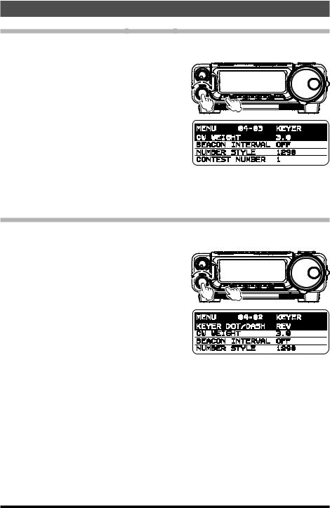
Setting the Keyer Weight (Dot/Dash) Ratio
This Menu item may be used to adjust the dot/dash ratio for the built-in Electronic Keyer. The default weighting is 3:1 (a dash is three times longer than a dot).
1. Press and hold in the [F] key for one second to activate the Menu mode. 2. Rotate the MULTI function knob to select
Menu Mode “04-03 [CW WEIGHT]”. 3. Press the MULTI function knob, and then
rotate it to set the weight to the desired val-
ue. The available adjustment range is a Dot/ Dash ratio of 2.5 - 4.5.
Default: 3.0
4.When the adjustment is satisfactory, press the MULTI function knob.
5.Press the [F] key to save the new setting and exit the Menu mode to normal operation.
Reversing the Keyer Polarity
For left-handed operators in a contest, for example, the polarity can be reversed easily in the Menu mode without changing the keyer connection (the default setting is “NOR”).
1. Press and hold in the [F] key for one second to activate the Menu mode. 2. Rotate the MULTI function knob to select Menu Mode “04-02 [KEYER DOT/DASH]”.
3. Press the MULTI function knob, and then rotate it to select “REV”.
4. When the adjustment is satisfactory, press the MULTI function knob.
5. Press the [F] key to save the new setting and exit the Menu mode to normal operation.
6 |
FT-891 Advance Manual |
CW Mode Operation
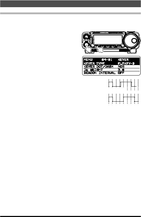
Selecting the Keyer Operating Mode
The configuration of the Electronic Keyer may be customized independently for the rear panel KEY jack of the FT-891. This permits utilization of Automatic Character Spacing (ACS), if desired.
1.Press and hold in the [F] key for one second to activate the Menu mode.
2.Rotate the MULTI function knob to select Menu Mode “04-01 [KEYER TYPE]”.
3.Press the MULTI function knob, and then rotate it to set the keyer to the desired mode. The available selections are:
OFF: |
The built-in Electronic Key- |
|
|
||
|
||
|
er is turned off (“straight key” |
|
|
mode). |
|
BUG: |
Dots will be generated au- |
|
|
tomatically by the keyer, but |
|
|
dashes must be sent manually. |
|
ELEKEY-A: A code elements (“Dot” or “Dash”) are automatically transmitted upon pressing either side of the paddle.
ACS
OFF Morse “E” & “T”
Inter-character Spacing too short
ACS
ON Morse “E” & “T”
ELEKEY-B: Pressing both sides of the paddle transmits the currently generated “Dash” followed by the “Dot” (or reverse order).
ELEKEY-Y: Pressing both sides of the paddle transmits the currently generated “Dash” followed by the “Dot” (or reverse order). While transmitting the “Dash”, the first transmitted “Dot” will not be stored.
ACS: |
Same as “ELEKEY” except that the spacing between characters is pre- |
|
cisely set by the keyer to be the same length as a dash (three dots in |
|
length). |
Default: ELEKEY-B
4.When the Menu selection is satisfactory, press the MULTI function knob.
5.Press the [F] key to save the new setting and exit the Menu mode to normal operation.
7 |
FT-891 Advance Manual |
CW Mode Operation
CW Delay Time Setting
During semi-break-in (not QSK) operation, the hang time of the transmitter, after you have finished sending, may be adjusted to a comfortable value consistent with your sending speed. This is the functional equivalent of the “VOX Delay” adjustment used on voice modes, and the delay may be varied anywhere between 30 msec and 3 seconds via Menu item “07-09 [CW BK-IN DELAY]”.
1. Press and hold in the [F] key for one second to activate the Menu mode. 2. Rotate the MULTI function knob to select
Menu Mode “07-09 [CW BK-IN DELAY]”. 3. Press the MULTI function knob, and then
rotate it to adjust the hang time (30 - 3000
msec).
Default: 200 msec 4. When the adjustment is satisfactory, press
the MULTI function knob.
5.Press the [F] key to save the new setting and exit the Menu mode to normal operation.
CW Pitch Adjustment
The center frequency of the receiver passband may be adjusted to the preferred CW tone. The pitch of the CW carrier offset may be varied between 300 Hz and 1050 Hz, in 10 Hz steps.
1. Press the [F] key repeatedly to find the “CW SETTING” list screen. 2. Rotate the MULTI function knob to select “PITCH”.
3. Press the MULTI function knob, the PITCH frequency pop-up screen will appear.
4. Rotate the MULTI function knob to adjust the PITCH (300 - 1050 Hz).
Default: 700 Hz
5.Press the MULTI function knob, then press and hold the [F] key for one second to exit the “CW SETTING” list screen and resume normal operation.
ρ CW Pitch function may be assigned to the [A], [B] or [C] key. Refer to “Changing the function assigned to the [A]/[B]/[C] keys” in the FT-891 Operating Manual.
CW Pitch: If the receiver is tuned to an exact “zero beat” on an incoming CW signal, you could not copy it (“Zero beat” implies a 0 Hz tone). Therefore, the receiver is offset several hundred Hz (typically), to produce a beat tone that can be heard. The BFO offset associated with this tuning (that produces the comfortable audio tone) is called the CW Pitch.
8 |
FT-891 Advance Manual |
CW Mode Operation
CW Spotting (Zero-Beating)
“Spotting” (zeroing in on a received CW station) is a handy technique to ensure you and the other station are precisely on the same frequency.
The Tuning Offset Indicator in the LCD display may also be observed, so that the receiver frequency can be adjusted to center the incoming station on the pitch corresponding to that of the transmitted signal.
Using the Auto Zeroing System
1. Press the [F] key repeatedly to find the “CW SETTING” list screen.
2. Rotate the MULTI function knob to select “ZIN”.
3. Press the MULTI function knob to cause the receiving frequency to zero-in automatically while receiving a CW signal.
4. Press and hold the [F] key for one second to exit the “CW SETTING” list screen and resume normal operation.
ρAuto Zeroing function may be assigned to the [A], [B] or [C] key. Refer to “Changing the function assigned to the [A]/[B]/[C] keys” in the FT-891 Operating Manual.
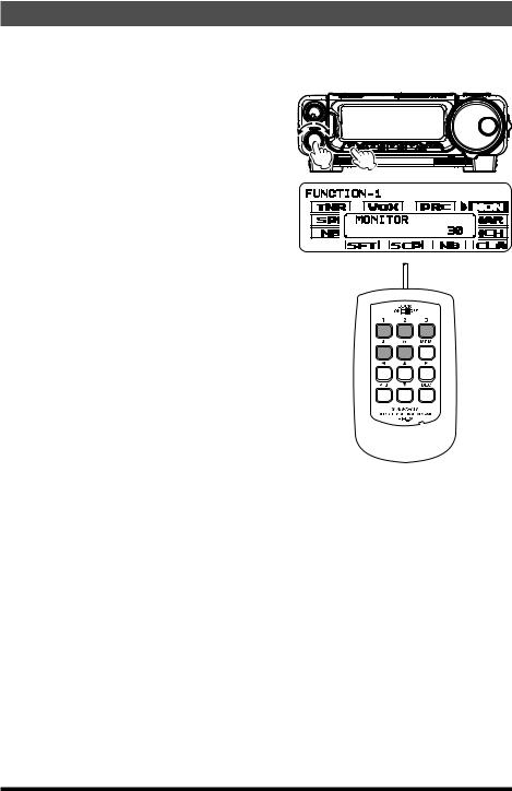
Using the SPOT System
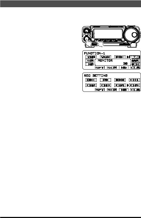
1. Press the [F] key repeatedly to find the “FUNCTION-1” list screen.
2. Rotate the MULTI function knob to select “MON”.
3. Press the MULTI function knob to activate the Monitor function, the Monitor level popup screen will appear.
4. Rotate the MULTI function knob to adjust the Monitor audio volume.
5. Press the MULTI function knob.
6. Press the [F] key repeatedly to find the “CW SETTING” list screen.
7. Rotate the MULTI function knob to select “ZIN”.
8.While you are pressing and holding the MULTI function knob, the tone is output from the speaker.
9.Press and hold the [F] key for one second to exit the “CW SETTING” list screen and resume normal operation.
ρSpot function may be assigned to the [A], [B] or [C] key. Refer to “Changing the function assigned to the [A]/[B]/[C] keys” in the FT-891 Operating Manual.
9 |
FT-891 Advance Manual |
CW Mode Operation
ρThe displayed frequency on the CW mode normally reflects the “zero beat” frequency of the offset carrier. That is, when receiving a signal at 14.100.00 MHz with a 700 Hz offset, the “zero beat” frequency of that CW carrier would be 14.100.70 MHz; which is what the FT-891 displays, by default. However, the display may be changed to be
identical to what would be seen when listening on the USB mode, by using Menu item “07-11 [CW FREQ DISPLAY]” and setting it to “FREQ” instead of the default “PITCH” setting.
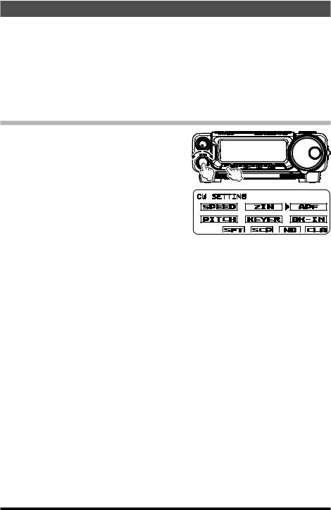
Audio Peak Filter
1.Press the [F] key repeatedly to find the “CW SETTING” list screen.
2.Rotate the MULTI function knob to select “APF”.
3.Press the MULTI function knob, then rotate
it to set the “APF” action to a comfortable level (-250 - +250 Hz).
Default: +250 Hz
ρThe APF bandwidth can be selected
from NARROW/MEDIUM/WIDE via the Menu item “12-01 [APF WIDTH]”.
4.To cancel the APF action, press the MULTI function knob, then press and hold the [F] key for one second to exit the “CW SETTING” list screen and resume normal operation.
ρThe APF may only be activated while the transceiver is in CW mode.
ρAudio Peak Filter function may be assigned to the [A], [B] or [C] key. Refer to “Changing the function assigned to the [A]/[B]/[C] keys” in the FT-891 Operating Manual.
10 |
FT-891 Advance Manual |
CW Mode Operation
Contest Memory Keyer
The CW message capability of the FT-891 may be utilized from the Front Control Panel, or the optional FH-2 Remote Control Keypad, which plugs into the rear panel REM/ALC jack.
Message Memory
Five CW memory channels, capable of retaining 50 characters each, are provided (the CW memory uses the PARIS standard for characters and word length).
Example: CQ CQ CQ DE W6DXC K (19 characters)
─ •─ • ── •─ ─ •─ • ── •─ ─ •─ • ── •─ ─ • • • |
•── ─ • • • • ─ • • ─ • •─ ─ •─ • ─ •─ |
||
(C) (Q) |
(C) (Q) |
(C) (Q) (D) (E) |
(W) (6) (D) (X) (C) (K) |
Storing a CW Message into Memory using a Keyer Paddle
1. First, set the message entry method to keyer entry. To activate the Menu mode, press and hold the [F] key in for one second. 2. Rotate the MULTI function knob to select
the CW Memory Register into which you wish to store the message; for now, we are
just setting the message entry technique to (Keyer entry).
“04-07 [CW MEMORY 1]” “04-08 [CW MEMORY 2]”
“04-09 [CW MEMORY 3]” “04-10 [CW MEMORY 4]” “04-11 [CW MEMORY 5]”
3.Press the MULTI function knob briefly, and then rotate it to set the selected CW Memory Register to “MESSAGE”. If you want to use a keyer paddle for message entry on all five memories, set Menu items #04-07 to #04-11 to “MESSAGE”.
4.Press the MULTI function knob to save the new setting.
5.Press the [F] key to exit to normal operation.
ρPARIS Word Length: By convention among CW and Amateur operators (utilized by ARRL and others), the length of one “word” of CW is defined as the length of the Morse Code characters spelling the word “PARIS”. This character (dot/dash/space) length is used for the specific definition of code speed in “words” per minute.
11 |
FT-891 Advance Manual |

CW Mode Operation
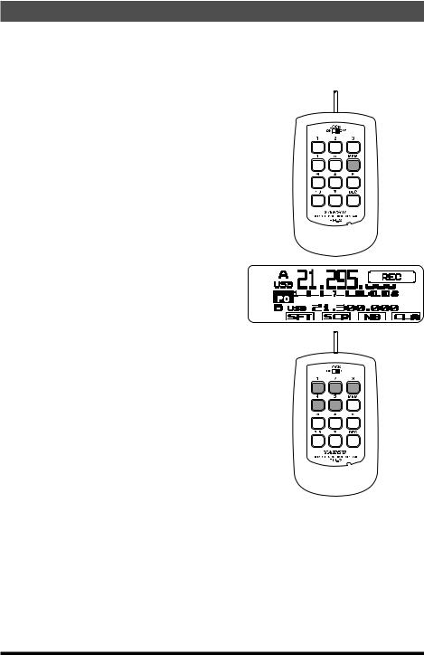
Message Memory Programming from the FT-891 Control Panel (Using a Keyer Paddle)
1.Set the operating mode to CW.
2.Set the “BK-IN” feature to “OFF”.
3.Turn the internal Electronic Keyer “ON”.
4. Press the [F] key repeatedly to find the “REC SETTING” list screen.
NOTE: This screen may be enabled/ disabled via Menu Mode “05-11
[REC SETTING]”.
5. Rotate the MULTI function knob to select “MEM”.
6. Press the MULTI function knob. A blinking “REC” icon will appear in the display.
7. Rotate the MULTI function knob to select any numbered [CH1] through [CH5].
8. Press the MULTI function knob to begin the memory storage process, and the “REC” icon will glow steadily.
9.Send the desired message using the keyer paddle.
NOTE: If you do not start keying within ten seconds, the memory storage process will be canceled.
10.Press the MULTI function knob once more at the end of the message. Up to 50 characters may be stored in each of the five memories.
11.Press and hold the [F] key for one second to exit the “REC SETTING” list screen and resume normal operation.
NOTE: Care must be exercised when sending to ensure that the spaces between letters and words are accurately done; if the timing is off, the spacing may not
come out right in the stored message. For ease in setting up the keyer memories, we recommend setting Menu item “04-01 [KEYER TYPE]” to “ACS” (Automatic Character Spacing) while programming the keyer memories.
12 |
FT-891 Advance Manual |
CW Mode Operation
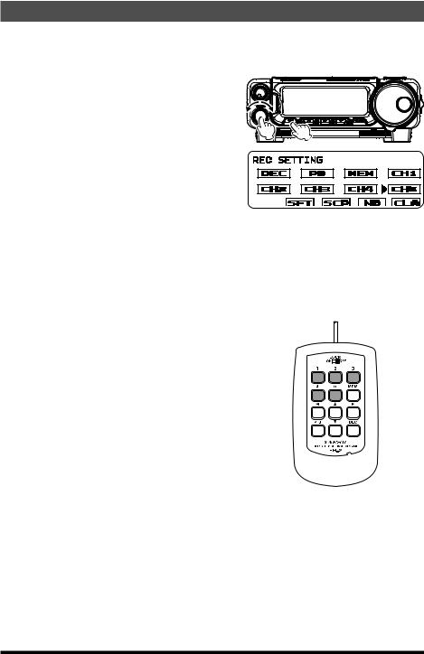
Message Memory Programming with the Optional FH-2 (Using the Keyer Paddle)
1.Set the operating mode to CW.
2.Set the “BK-IN” feature to “OFF”.
3.Turn the internal Electronic Keyer “ON”.
4. Press the [MEM] key on the FH-2. A blinking “REC” icon will appear in the display.
5. Press any of the FH-2 keys numbered [1] through [5] to begin the memory storage process, and the “REC” icon will glow steadily.
6. Send the desired message using the keyer paddle.
NOTE: If you do not start keying within ten seconds, the memory storage process will be canceled.
7. Press the [MEM] key on the FH-2 once more at the end of your message. Up to 50 characters may be stored in each of the five memories.
NOTE: Care must be exercised when sending to ensure that the spaces between letters and words are accurately done; if the timing is off, the spacing may not come out right in the stored message. For ease in setting up the keyer memories, we recommend setting Menu item “0401 [KEYER TYPE]” to “ACS” (Automatic Character Spacing) while programming the keyer memories.
13 |
FT-891 Advance Manual |

CW Mode Operation
Checking the CW Memory Contents from the FT-891 Front Control Panel
1.Set the operating mode to CW.
2.Set the “BK-IN” feature to “OFF”.
3. Press the [F] key to find the “FUNCTION-1” list screen.
4. Rotate the MULTI function knob to select “MON”.
5. Press the MULTI function knob, the Monitor level pop-up screen will appear.
6. Rotate the MULTI function knob to set the Monitor volume level (0 - 100).
7. Press the MULTI function knob or the [F] key.
8. Press the [F] key to find the “REC SETTING” list screen.
NOTE: This screen may be enabled/ disabled via Menu Mode “05-11
[REC SETTING]”.
9.Rotate the MULTI function knob to select a memory [CH1] - [CH5] that was previously recorded.
10.Press the MULTI function knob to hear the CW message played in the sidetone monitor. No RF energy will be transmitted.
11.Press and hold the [F] key for one second to exit the “REC SETTING” list screen and resume normal operation.
14 |
FT-891 Advance Manual |
CW Mode Operation
Checking the CW Memory Contents with the Optional FH-2
1.Set the operating mode to CW.
2.Set the “BK-IN” feature to “OFF”.
3. Press the [F] key to find the “FUNCTION-1” list screen.
4. Rotate the MULTI function knob to select “MON”.
5. Press the MULTI function knob, the Monitor level pop-up screen will appear.
6. Rotate the MULTI function knob to set the Monitor volume level (0 - 100).
7. Press the MULTI function knob or the [F] key.
8.Press and hold the [F] key for one second to exit the “FUNCTION-1” list screen and re-
sume normal operation.
9. Press the FH-2 [CH1] - [CH5] key to select a previously recorded memory. The CW message will be played in the sidetone monitor. No RF energy will be transmitted.
15 |
FT-891 Advance Manual |
CW Mode Operation
Playback the CW Message On-The-Air using the FT-891 Display Control Panel
1.Set the operating mode to CW.
2.Set the “BK-IN” feature to “ON”.
3. Press the [F] key to find the “REC SETTING” list screen.
NOTE: This screen may be enabled/ disabled via Menu Mode “05-11
[REC SETTING]”.
4. Rotate the MULTI function knob to select a previously recorded CW memory [CH1] - [CH5].
5. Press the MULTI function knob, the CW message programmed in the selected Memory Register will be transmitted on the air.
6.Press and hold the [F] key for one second to exit the “REC SETTING” list screen and resume normal operation.
Playback the CW Message On-The-Air using the Optional FH-2
1.Set the operating mode to CW.
2.Set the “BK-IN” feature to “ON”.
3. Press the FH-2 [CH1] - [CH5] key, depending on which CW Memory Register message you wish to transmit. The programmed message will be transmitted on the air.
16 |
FT-891 Advance Manual |
CW Mode Operation
Text Memory
The five channels of CW message memory (up to 50 characters each) may also be programmed using a text-entry technique. This method is somewhat slower than sending the message directly from the keyer paddle, but accuracy of character spacing is ensured. Be sure to enter the character “}” at the end of the text message.
Example 1: CQ CQ CQ DE W6DXC K} (20 characters)
The sequential Contest Number (“Count up”) feature is another powerful feature that may be utilized within the CW Memory Keyer by entering the # symbol.
Example 2: 599 10 200 # K} (15 characters)
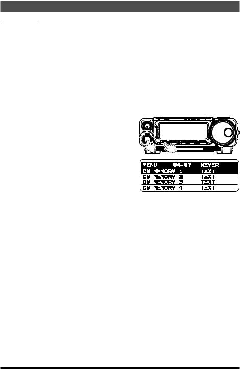
Text Memory Storage
1. Press and hold in the [F] key for one second to activate the Menu mode. 2. First, set the message entry method to Text Entry. Rotate the MULTI function knob to
select the CW Memory Register into which you wish to store the message using the Text Entry method. “04-07 [CW MEMORY 1]” “04-08 [CW MEMORY 2]” “04-09 [CW MEMORY 3]”
“04-10 [CW MEMORY 4]”
“04-11 [CW MEMORY 5]”
3.Press the MULTI function knob, and then rotate it to set the selected CW Memory Register to “TEXT”. If you want to use text message entry on all memories, set all five Menu items (#04-07 to #04-11) to “TEXT”.
4.Press the MULTI function knob to save the new setting.
5.Press the [F] key to exit to normal operation.
ρThe following texts are programmed to MEMORY 4 and MEMORY 5 as the factory
default:
MEMORY 4: DE FT-891 K} MEMORY 5: R 5NN K}
17 |
FT-891 Advance Manual |
CW Mode Operation
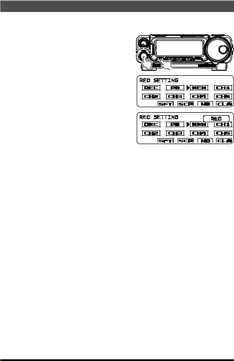
Text Message Programming from the FT-891 Control Panel
1. Set the operating mode to CW.
2. Press the [F] key repeatedly, to find the “REC SETTING” list screen. NOTE: This screen may be enabled/ disabled via Menu Mode “05-11
[REC SETTING]”. 3. Rotate the MULTI function knob to select
“MEM”. 4. Press the MULTI function knob. A blinking “REC” icon will appear in the display.
5. Rotate the MULTI function knob to select
any channel [CH1] through [CH5]. 6. Press the MULTI function knob. The “CW TEXT” screen will appear.
7. Press the [B](EDT) key. The text input screen will appear.
8.Rotate the MULTI function knob to select the letters, numbers, or symbols of the desired label, then press the MULTI function knob.
9.Press the MULTI function knob.
10.Repeat step 8 and 9 to program the remaining letters, numbers, or symbols of the desired text. Up to 50 characters may be stored in each of the five memories.
ρRotate the MULTI function knob to set the cursor position and press the [B](CE) key to erase and input characters.
11.When text entry is complete, press the [C](ENT) key.
12.Press the [A](BCK) key to exit the text input screen.
13.Press and hold the [F] key for one second to exit the “REC SETTING” list screen and resume normal operation.
18 |
FT-891 Advance Manual |

CW Mode Operation
Text Message Programming with the Optional FH-2
1. Set the operating mode to CW.
2. Press the [MEM] key on the FH-2. A blinking “REC” icon will appear in the display. 3. Press any of the FH-2 keys numbered [1]
through [5], to select the desired CW Memory Register that you wish to program with text.
4. Press the [MEM] key on the FH-2. The text input screen will appear.
5. Rotate the MULTI function knob to select the letters, numbers, or symbols of the desired label, then press the MULTI function knob.
6.Press the MULTI function knob.
7.Repeat step 5 and 6 to program the remaining letters, numbers, or symbols of the desired text. Up to 50 characters may be stored in each of the five memories.
ρRotate the MULTI function knob to set the cursor position and press the [B](CE) key to erase and input characters.
8.When the message is complete, add the “}” character at the end to signify the termination of the message.
9.When the text entry is complete, press the [B](ENT) key.
10.Press and hold the FH-2 [MEM] key for one second to exit the text input screen and resume normal operation.
19 |
FT-891 Advance Manual |
CW Mode Operation
Checking the CW Memory Contents from the FT-891 Front Control Panel
1.Set the operating mode to CW.
2.Set the “BK-IN” feature to “OFF”.
3. Press the [F] key repeatedly, to find the “FUNCTION-1” list screen.
4. Rotate the MULTI function knob to select “MON”.
5. Press the MULTI function knob, the Monitor level pop-up screen will appear.
6. Rotate the MULTI function knob to set the Monitor volume level (0 - 100).
7. Press the MULTI function knob or the [F] key.
8. Press the [F] key repeatedly, to find the “REC SETTING” list screen.
NOTE: This screen may be enabled/ disabled via Menu Mode “05-11
[REC SETTING]”.
9.Rotate the MULTI function knob to select a memory [CH1] - [CH5] that was previously recorded.
10.Press the MULTI function knob to hear the CW message played in the sidetone monitor. No RF energy will be transmitted.
11.Press and hold the [F] key for one second to exit the “REC SETTING” list screen and resume normal operation.
20 |
FT-891 Advance Manual |
CW Mode Operation
Checking the CW Memory Contents with the Optional FH-2
1.Set the operating mode to CW.
2.Set the “BK-IN” feature to “OFF”.
3. Press the [F] key repeatedly, to find the “FUNCTION-1” list screen.
4. Rotate the MULTI function knob to select “MON”.
5. Press the MULTI function knob, the Monitor level pop-up screen will appear.
6. Rotate the MULTI function knob to set the Monitor volume level (0 - 100).
7. Press the MULTI function knob or the [F] key.
8.Press and hold the [F] key for one second to exit the “FUNCTION-1” list screen and re-
sume normal operation.
9. Press the FH-2 [CH1] - [CH5] key to select a previously recorded memory. The CW message will be played in the sidetone monitor. No RF energy will be transmitted.
21 |
FT-891 Advance Manual |

CW Mode Operation
Playback the CW Message On-The-Air using the FT-891 Display Control Panel
1.Set the operating mode to CW.
2.Set the “BK-IN” feature to “ON”.
3. Press the [F] key repeatedly, to find the “REC SETTING” list screen.
NOTE: This screen may be enabled/ disabled via Menu Mode “05-11
[REC SETTING]”.
4. Rotate the MULTI function knob to select a previously recorded CW memory [CH1] - [CH5].
5. Press the MULTI function knob, the CW message programmed in the selected Memory Register will be transmitted on the air.
6.Press and hold the [F] key for one second to exit the “REC SETTING” list screen and resume normal operation.
Playback the CW Message On-The-Air using the Optional FH-2
1.Set the operating mode to CW.
2.Set the “BK-IN” feature to “ON”.
3. Press the FH-2 [CH1] - [CH5] key, depending on which CW Memory Register message you wish to transmit. The programmed message will be transmitted on the air.
22 |
FT-891 Advance Manual |
CW Mode Operation
Contest Number Programming
Use this process when beginning a contest, or if the count becomes out of sync with the contact number in the middle of a contest.
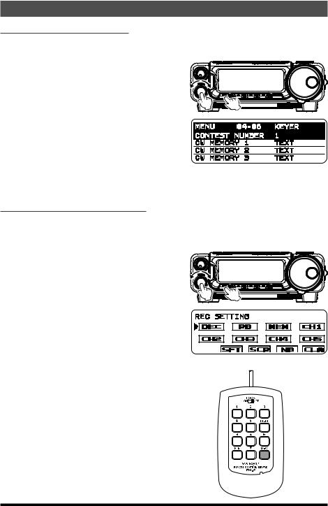
1. Press and hold in the [F] key for one second to activate the Menu mode. 2. Rotate the MULTI function knob to select Menu Mode “04-06 [CONTEST NUMBER]”.
The current contest number will appear on the LCD display.
3. Press the MULTI function knob, and then rotate it to set the Contest Number to the desired value.
4.Press the MULTI function knob to save the new setting.
5.Press the [F] key to exit the Menu mode and resume normal operation.
Decrementing the Contest Number
Use this process if the current contest number gets slightly ahead of the actual contact number (in case of a duplicate QSO, for example).
Using the FT-891 Display Control Panel
1. Press the [F] key repeatedly, to find the “REC SETTING” list screen. NOTE: This screen may be enabled/ disabled via Menu Mode “05-11
[REC SETTING]”. 2. Rotate the MULTI function knob to select
“DEC”. 3. Press the MULTI function knob. The current Contest Number will be reduced by one.
Using the Optional FH-2
Press the FH-2 [DEC] key momentarily. The current Contest Number will be reduced by one. Press the FH-2 [DEC] key as many times as necessary to reach the desired number. If it is reduced too far, use the “Contest Number Programming” technique described previously.
23 |
FT-891 Advance Manual |
CW Mode Operation
Transmitting in the Beacon Mode
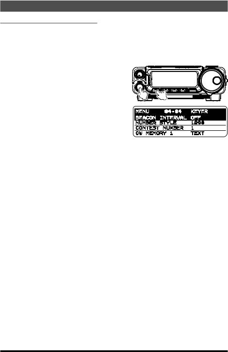
In “Beacon” mode, it is possible to repeatedly transmit any message programmed, either via paddle input, or via the “Text” input method. The time delay between message repeats may be set anywhere between 1 and 690 seconds (1 - 240 sec (1 sec/step) or 270 - 690 sec (30 sec/step)) via Menu Mode “04-04 [BEACON INTERVAL]”. To stop the message from repeating in “Beacon” mode, set this Menu Mode to “OFF”.
1. Press and hold in the [F] key for one second to activate the Menu mode. 2. Rotate the MULTI function knob to select Menu Mode “04-04 [BEACON INTERVAL]”.
The current interval time will appear on the LCD display.
3. Press the MULTI function knob, and then rotate it to set the interval time to the desired value.
4.Press the MULTI function knob to save the new setting.
5.Press the [F] key to exit the Menu mode and resume normal operation.
To transmit the message using the FT-891 Display Control Panel:
1.Set the “BK-IN” feature to “ON”
2.Either Full-break-in or Semi-break-in will be engaged, depending on the setting of Menu Mode “07-08 [CW BK-IN TYPE]”.
3.Press the [F] key repeatedly, to find the “REC SETTING” list screen.
NOTE: This screen may be enabled/disabled via Menu Mode “05-11 [REC SETTING]”.
4.Rotate the MULTI function knob to select a [CH1] - [CH5].
5.Press the MULTI function knob. Repetitive transmission of the Beacon message will begin.
To transmit the message using the Optional FH-2:
1.Set the “BK-IN” feature to “ON”
2.Either Full-break-in or Semi-break-in will be engaged, depending on the setting of Menu Mode “07-08 [CW BK-IN TYPE]”.
3.Press an FH-2 [1] - [5] key. Repetitive transmission of the Beacon message will begin.
24 |
FT-891 Advance Manual |
FM Mode Operation
Basic Operation
1.Press and hold the [BAND(MODE)] key for one second.
The “MODE SELECT” screen will appear in the display.
2. Rotate the DIAL knob to select the “FM” mode.
3. Set the transceiver to the desired frequency.
4. Press the microphone PTT switch to transmit. Speak into the microphone in a normal voice level. Release the PTT switch to return to receive.
ρChange the MULTI function knob frequency step, follow the below procedure:
1.Press and hold in the [F] key for one second.
2.Rotate the MULTI function knob to select Menu Mode “14-07 [FM CH STEP]”.
3.Press the MULTI function knob, and then rotate it to select one of the frequency steps in the following order.
5 kHz, 6.25 kHz, 10 kHz, 12.5 kHz, 15 kHz, 20 kHz, 25 kHz
4.Press the MULTI function knob to save the new setting.
5.Press the [F] key to exit the Menu mode and resume normal operation.
ρMicrophone gain may be adjusted via Menu Mode “16-09 [FM MIC GAIN]”. At the factory, a default level has been programmed that should be satisfactory for most situations. To change the microphone gain, follow the below procedure:
1.Press and hold in the [F] key for one second.
2.Rotate the MULTI function knob to select Menu Mode “16-09 [FM MIC GAIN]”.
3.Press the MULTI function knob, and then rotate it to adjust the microphone gain.
4.Press the MULTI function knob to save the new setting.
5.Press the [F] key to exit the Menu mode and resume normal operation.
ρFM is only used in the 28 MHz and 50 MHz Amateur bands covered by the FT-891. Please do not use FM on any other bands.
25 |
FT-891 Advance Manual |

FM Mode Operation
Repeater Operation
The FT-891 may be utilized on 29 MHz and 50 MHz repeaters.
1. Rotate the DIAL to set the FT-891 to the desired repeater output frequency (downlink from the repeater).
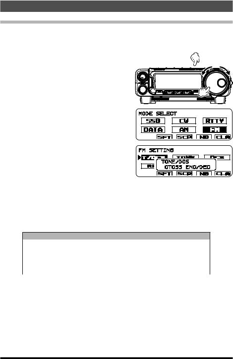
2. Press the [F] key repeatedly, to find the “FM SETTING” list screen. NOTE: This screen may be enabled/
disabled via Menu Mode “05-10
[FM SETTING]”.
3. Rotate the MULTI function knob to select [T/DCS], then press the MULTI function knob.
4. Rotate the MULTI function knob to select the desired CTCSS mode. If the repeater requires an uplink encoding tone, select “CTCSS ENC”. To enable both uplink and downlink encode/decode operation, choose “CTCSS ENC/DEC”.
5. Press the MULTI function knob to save the new setting.
6. Rotate the MULTI function knob to select [TONE], and then press the MULTI function knob.
7. |
Rotate the MULTI function knob to select the desired CTCSS Tone to be used. A total |
|||||||||||
|
of 50 standard CTCSS tones are provided (see the CTCSS Tone Chart). |
|||||||||||
|
|
|
|
|
|
|
|
|
|
|
|
|
|
|
|
|
|
CTCSS Tone Frequency (Hz) |
|
|
|
|
|||
|
|
67.0 |
69.3 |
71.9 |
74.4 |
77.0 |
79.7 |
82.5 |
85.4 |
88.5 |
91.5 |
|
|
|
94.8 |
97.4 |
100.0 |
103.5 |
107.2 |
110.9 |
114.8 |
118.8 |
123.0 |
127.3 |
|
|
|
131.8 |
136.5 |
141.3 |
146.2 |
151.4 |
156.7 |
159.8 |
162.2 |
165.5 |
167.9 |
|
|
|
171.3 |
173.8 |
177.3 |
179.9 |
183.5 |
186.2 |
189.9 |
192.8 |
196.6 |
199.5 |
|
|
|
203.5 |
206.5 |
210.7 |
218.1 |
225.7 |
229.1 |
233.6 |
241.8 |
250.3 |
254.1 |
|
8. |
Press the MULTI function knob to save the new setting |
|
|
|
|
|||||||
9. |
Rotate the MULTI function knob to select [RPT], then press the MULTI function knob. |
|||||||||||
10. Rotate the MULTI function knob to select the desired repeater shift direction. The selections are:
“SIMP” (simplex) / “[+]” (plus shift) / “[-]” (minus shift) Where “SIMP” represents “Simplex” operation (not used on a repeater).
11.Press the MULTI function knob to save the new setting.
12.Press and hold the [F] key for one second to exit the “FM SETTING” list screen and resume normal operation.
13.Press and hold the microphone PTT switch to begin transmitting. You will observe that the transmit frequency is shifted corresponding to the programming set up in the previous steps. Speak into the microphone in a normal voice level. Release the PTT
switch to return to the receive mode.
ρThe conventional repeater shift used on 29 MHz is 100 kHz, while on the 50 MHz band
the shift may vary between 500 kHz and 1.7 MHz (or more). To program the proper repeater shift, use Menu Mode “09-04 [RPT SHIFT 28MHz]” (28 MHz), and “09-05 [RPT SHIFT 50MHz]” (50 MHz) as appropriate.
26 |
FT-891 Advance Manual |
FM Mode Operation
Tone Squelch Operation
The “Tone Squelch” may be activated to silence the receiver until an incoming signal modulated with a matching CTCSS tone is received. The receiver squelch will then open only when a signal with the selected CTCSS tone is received.
1. Press and hold the [BAND(MODE)] key for one second.
The “MODE SELECT” screen will appear in the display. 2. Rotate the DIAL knob to select the “FM”
mode. 3. Press the [F] key repeatedly, to find the “FM
SETTING” list screen.
NOTE: This screen may be enabled/ disabled via Menu Mode “05-10
[FM SETTING]”. 4. Rotate the MULTI function knob to select
[T/DCS], then press the MULTI function
knob. 5. If CTCSS Tone operation is desired, rotate
the MULTI function knob to select “CTCSS ENC/DEC”, then press the MULTI function
knob.
6. Press the MULTI function knob to save the new setting.
7. Rotate the MULTI function knob to select [TONE], and then press the MULTI function knob. 8. Rotate the MULTI function knob to select the desired CTCSS Tone to be used. A total
of 50 standard CTCSS tones are provided (see the CTCSS Tone Chart).
CTCSS Tone Frequency (Hz)
67.0 |
69.3 |
71.9 |
74.4 |
77.0 |
79.7 |
82.5 |
85.4 |
88.5 |
91.5 |
94.8 |
97.4 |
100.0 |
103.5 |
107.2 |
110.9 |
114.8 |
118.8 |
123.0 |
127.3 |
131.8 |
136.5 |
141.3 |
146.2 |
151.4 |
156.7 |
159.8 |
162.2 |
165.5 |
167.9 |
171.3 |
173.8 |
177.3 |
179.9 |
183.5 |
186.2 |
189.9 |
192.8 |
196.6 |
199.5 |
203.5 |
206.5 |
210.7 |
218.1 |
225.7 |
229.1 |
233.6 |
241.8 |
250.3 |
254.1 |
9. Press the MULTI function knob to save the new setting.
10. Press and hold the [F] key for one second to exit the “FM SETTING” list screen and resume normal operation.
ρTo set the Tone Squelch Operation to “OFF”:
1.Press the [F] key repeatedly, to find the “FM SETTING” list screen.
2.Rotate the MULTI function knob to select [T/DCS], then press the MULTI function knob.
3.Press and hold the [F] key for one second to exit the “FM SETTING” list screen and resume normal operation.
27 |
FT-891 Advance Manual |
FM Mode Operation
DCS Operation
The “DCS” may be activated to silence the receiver until an incoming signal modulated with a matching DCS code is received. The receiver squelch will then open only when a signal with the selected DCS code is received.
1. Press and hold the [BAND(MODE)] key for one second.
The “MODE SELECT” screen will appear in the display. 2. Rotate the DIAL knob to select the “FM” mode.
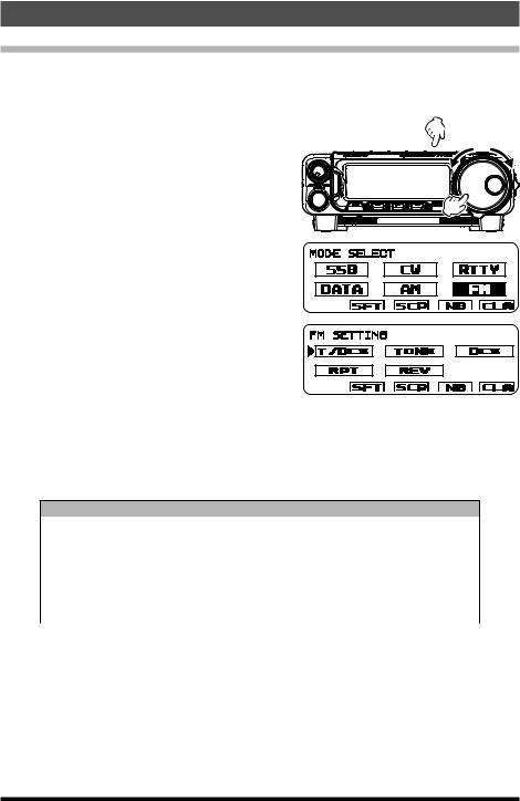
3. Press the [F] key repeatedly, to find the “FM SETTING” list screen.
NOTE: This screen may be enabled/ disabled via Menu Mode “05-10
[FM SETTING]”. 4. Rotate the MULTI function knob to select
[T/DCS], then press the MULTI function
knob. 5. If DCS operation is desired, rotate the
MULTI function knob to select “DCS”, then press the MULTI function knob.
6.Press the MULTI function knob to save the new setting.
7.Rotate the MULTI function knob to select [DCS], and then press the MULTI function knob.
8.Rotate the MULTI function knob to select the desired DCS Code to be used. A total of 104 DCS codes are provided (see the DCS Code Chart).
DCS Code
023 |
025 |
026 |
031 |
032 |
036 |
043 |
047 |
051 |
053 |
054 |
065 |
071 |
072 |
073 |
074 |
114 |
115 |
116 |
122 |
125 |
131 |
132 |
134 |
143 |
145 |
152 |
155 |
156 |
162 |
165 |
172 |
174 |
205 |
212 |
223 |
225 |
226 |
243 |
244 |
245 |
246 |
251 |
252 |
255 |
261 |
263 |
265 |
266 |
271 |
274 |
306 |
311 |
315 |
325 |
331 |
332 |
343 |
346 |
351 |
356 |
364 |
365 |
371 |
411 |
412 |
413 |
423 |
431 |
432 |
445 |
446 |
452 |
454 |
455 |
462 |
464 |
465 |
466 |
503 |
506 |
516 |
523 |
526 |
532 |
546 |
565 |
606 |
612 |
624 |
627 |
631 |
632 |
654 |
662 |
664 |
703 |
712 |
723 |
731 |
732 |
734 |
743 |
754 |
- |
9.Press the MULTI function knob to save the new setting.
10.Press and hold the [F] key for one second to exit the “FM SETTING” list screen and resume normal operation.
ρTo set the DCS Operation to “OFF”:
1.Press the [F] key repeatedly, to find the “FM SETTING” list screen.
2.Rotate the MULTI function knob to select [T/DCS], and then press the MULTI function knob.
3.Press and hold the [F] key for one second to exit the “FM SETTING” list screen and resume normal operation.
28 |
FT-891 Advance Manual |
Interference Rejection
CONTOUR Control Operation
The Contour filter system provides a gentle perturbation of the IF filter passband. The Contour is set to either suppress, or boost specific frequency components, and thus enhance the sound and readability of a received signal.
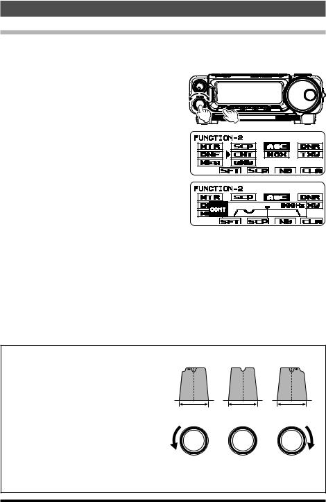
1. Press the [F] key repeatedly, to find the “FUNCTION-2” list screen. 2. Rotate the MULTI function knob to select
“CNT”. 3. Press the MULTI function knob, and then ro-
tate it to achieve the most natural sounding
audio reproduction of the incoming signal. 4. When the adjustment is completed, press
and hold the [F] key for one second to exit the “FUNCTION-2” list screen and resume normal operation.
ρTo set the CONTOUR Operation will be set to “OFF”:
1.Press the [F] key repeatedly, to find the “FUNCTION-2” list screen.
2.Rotate the MULTI function knob to select [CNT], then press the MULTI function knob.
3.Press and hold the [F] key for one second to exit the “FUNCTION-2” list screen and resume normal operation.
ρCONTOUR function may be assigned to the [A], [B] or [C] key. Refer to “Changing the function assigned to the [A]/[B]/[C] keys” in the FT-891 Operating Manual.
ρThe Contour function attenuation and bandwidth can be set in Menu Mode “12-02 [CONTOUR LEVEL]” and “12-03 [CONTOUR WIDTH]” (refer to the instructions on the below).
Refer to Figure (B), this illustrates a “dip” in |
(A) |
(B) |
(C) |
|
the center of the Contour filter passband. |
|
|
|
|
The Contour filter places a low-Q “notch” in |
|
|
|
|
the passband, corresponding to the settings |
|
|
|
|
of Menu Mode “12-02 [CONTOUR LEVEL]” |
|
|
|
|
and “12-03 [CONTOUR WIDTH]”. Counter- |
IF BANDWIDTH |
IF BANDWIDTH |
IF BANDWIDTH |
|
clockwise rotation of the MULTI function knob |
||||
MULTI |
MULTI |
MULTI |
||
causes the notch to move toward a lower fre- |
||||
quency within the passband, while clockwise |
|
|
|
|
rotation causes the notch to move toward a |
|
|
|
|
higher frequency within the passband. |
|
|
|
By removing interference or unwanted frequency components of the incoming signal, it is possible to make the desired signal rise out of the background noise/interference, and significantly enhance intelligibility.
29 |
FT-891 Advance Manual |
Interference Rejection
WIDTH (IF DSP Bandwidth) Tuning (SSB/CW/RTTY/DATA Modes)
The IF WIDTH tuning system allows the width of the DSP IF passband to be varied, this may reduce or eliminate interference.
Moreover, the bandwidth may actually be expanded from the default setting, this may enhance incoming signal fidelity when interference on the band is low.
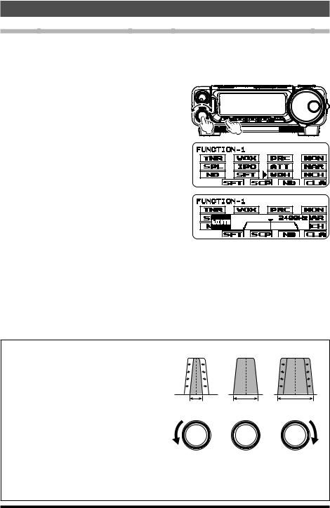
1. Press the [F] key repeatedly, to find the “FUNCTION-1” list screen. 2. Rotate the MULTI function knob to select
“WDH”. 3. Press the MULTI function knob, and then
rotate it counter-clockwise to narrow the
bandwidth and reduce interference. ρ To increase the bandwidth, rotate the knob clockwise.
4. When the adjustment is completed, press
the MULTI function knob. 5. Press and hold the [F] key for one second
to exit the “FUNCTION-1” list screen and resume normal operation.
ρTo set the IF WIDTH Operation to “OFF”:
1.Press the [F] key repeatedly, to find the “FUNCTION-1” list screen.
2.Rotate the MULTI function knob to select “WDH”, and then press the MULTI function knob.
3.Press and hold the [F] key for one second to exit the “FUNCTION-1” list screen and resume normal operation.
ρWIDTH function may be assigned to the [A], [B] or [C] key. Refer to “Changing the function assigned to the [A]/[B]/[C] keys” in the FT-891 Operating Manual.
Referring to Figure (B), the default bandwidth of the SSB mode is illustrated.
By rotating the MULTI function knob to the left, the bandwidth will narrow (see Figure (A)), while rotation of the MULTI function knob to the right, will increase the bandwidth as depicted in Figure (C).
The default bandwidths, and total bandwidth adjustment range, will vary according to the operating mode:
(A) |
(B) |
(C) |
IF BANDWIDTH IF BANDWIDTH IF BANDWIDTH
MULTI |
MULTI |
MULTI |
SSB Mode: 1.8 kHz - 3.2 kHz (default: 2.4 kHz). CW Mode: 500 Hz - 3 kHz (default: 2.4 kHz)
RTTY/DATA (LSB, USB) Modes: 500 Hz - 3 kHz (default: 500 Hz) AM Mode: Fixed at 9 kHz
FM/DATA-FM Modes: Fixed at 16 kHz
30 |
FT-891 Advance Manual |
Loading...