


 Loading...
FT-710
Operation Manual

About this Manual
The FT-710 is a leading-edge transceiver with a number of new and exciting features, some of which may be unfamiliar to you. In order to gain the most enjoyment and operating efficiency from the FT-710, we recommend that you read this manual in its entirety, and keep it handy for reference as you explore the many capabilities of this new transceiver.
Before using the FT-710, be sure to read this manual.
How to read this operation manual
Two methods are used to select an item displayed on the FT-710 Function Screen: “Operate by touching the item directly on the display”; and “Turn the [FUNC] knob to select the item and then press the [FUNC] knob”.
Subsequently, in this manual, the operations that can be performed either by touching the Function Screen, or by turning and pressing the [FUNC] knob are abbreviated to “Select [DISPLAY SETTING] → [DISPLAY] → [LED DIMMER]”; as described in the following:
Example: How to adjust the brightness of the LED
1.Press the [FUNC] knob to display the function screen.
2.Touch [DISPLAY SETTING] on the function screen, or rotate the [FUNC] knob to select [DISPLAY SETTING] and then press the [FUNC] knob.
3.Touch [DISPLAY] on the display or rotate the [FUNC] knob to select [DISPLAY] and then press the [FUNC] knob.
4.Touch the setting section of [LED DIMMER] on the display, or rotate the [FUNC] knob to select [LED DIMMER] and then press the [FUNC] knob.
5.Rotate the [FUNC] knob, or touch “<” or “>” on either side of the value to adjust the brightness.
The following notations are also used in this manual:
This icon indicates cautions and alerts the user should be aware of.
This icon indicates helpful notes, tips and information.
1
Table of Contents
General Description........................................ |
4 |
Safety Precautions.......................................... |
6 |
Accessories & Options.................................... |
8 |
Installation and Interconnections..................... |
9 |
Antenna Considerations...................................... |
9 |
Antenna Connections.......................................... |
9 |
Power Cable Connections.................................. |
9 |
Microphone, Headphone, Key, Keyer and |
|
FH-2 Connections............................................. |
10 |
Linear Amplifier Interconnections...................... |
11 |
VL-1000 Linear Amplifier Interconnections.... |
11 |
Display connections.......................................... |
12 |
Remote operation (LAN unit “SCU-LAN10”) |
|
connection......................................................... |
12 |
AESS (Acoustic Enhanced |
|
Speaker System)........................................... |
13 |
SP-40 connections............................................ |
13 |
Rear Panel.................................................... |
14 |
TUNER/LINEAR........................................ |
14 |
ANT........................................................... |
14 |
GND.......................................................... |
14 |
EXT SPKR................................................. |
14 |
REM/ALC.................................................. |
14 |
KEY........................................................... |
14 |
RTTY/DATA............................................... |
14 |
USB........................................................... |
14 |
USB Jack.................................................. |
14 |
EXT-DISPLAY........................................... |
14 |
DC IN........................................................ |
14 |
SSM-75E Microphone Switches.................... |
15 |
Display Indications........................................ |
16 |
Meter Display............................................ |
17 |
Operation MODE Display.......................... |
17 |
Operation status Display........................... |
17 |
HI-SWR Display........................................ |
17 |
Frequency Display (VFO-A)...................... |
18 |
Keyboard Frequency Entry....................... |
18 |
Tuning in 1 MHz or 1 kHz Steps............... |
18 |
Frequency Display (VFO-B)...................... |
18 |
When the clarifier function is active.......... |
18 |
Operation of the display [FUNC] knob...... |
19 |
Filter Function Display............................... |
20 |
Turn the spectrum display OFF................ |
20 |
Information displayed on the |
|
scope screen............................................. |
20 |
Important Receiver Settings...................... |
21 |
ATT (Attenuator)....................................... |
21 |
IPO............................................................ |
21 |
DNF (Digital NOTCH Filter)...................... |
21 |
AGC (Automatic Gain Control).................. |
21 |
Information displayed on |
|
the scope screen....................................... |
22 |
Scope Display Setting............................... |
22 |
CENTER/CURSOR/FIX............................ |
22 |
CENTER................................................... |
22 |
CURSOR.................................................. |
22 |
FIX............................................................ |
23 |
3DSS......................................................... |
23 |
MULTI....................................................... |
23 |
EXPAND................................................... |
24 |
SPAN........................................................ |
24 |
SPEED...................................................... |
24 |
Set with the FUNC knob........................... |
25 |
LEVEL....................................................... |
25 |
PEAK........................................................ |
25 |
MARKER................................................... |
26 |
COLOR..................................................... |
26 |
Adjust contrast.......................................... |
26 |
Adjusting the brightness (DIMMER).......... |
26 |
Other display settings........................................ |
27 |
Screen Saver................................................. |
27 |
Inputting the Call Sign.................................... |
27 |
Front Panel Controls & Switches.................. |
30 |
ON/OFF (LOCK) Switch............................ |
30 |
SD memory card slot................................. |
30 |
TUNE......................................................... |
30 |
VOX/MOX................................................. |
30 |
Adjusts the VOX GAIN.............................. |
30 |
Adjusts the VOX Delay Time..................... |
30 |
Adjusts the VOX anti-trip sensitivity.......... |
31 |
PHONES Jack........................................... |
31 |
MIC............................................................ |
31 |
MAIN dial................................................... |
31 |
WIRE STAND............................................ |
31 |
STEP • MCH/ ............................... |
32 |
DSP interference removal functions......... |
32 |
1. SHIFT.................................................... |
33 |
2. WIDTH.................................................. |
33 |
3. NOTCH................................................. |
33 |
4. CONTOUR............................................ |
34 |
Adjusting the GAIN of the |
|
CONTOUR Circuit................................. |
34 |
Sets the Bandwidth (“Q”) of the |
|
CONTOUR Circuit................................. |
34 |
5. APF....................................................... |
34 |
DSP RESET.............................................. |
34 |
DNR (Digital Noise Reduction).................. |
35 |
Adjusting the DNR Level............................ |
35 |
A/B............................................................. |
35 |
BAND (Operating Band Selection)................. |
35 |
QMB (Quick Memory Bank)...................... |
35 |
QMB Channel Storage.............................. |
35 |
QMB Channel Recall................................ |
35 |
Changing the number of QMB channels... |
35 |
VMI (VFO mode indicator)........................ |
36 |
BUSY/TX indicator.................................... |
36 |
NAR (Narrow)............................................ |
36 |
FINE/FAST................................................ |
36 |
RF GAIN/SQL............................................ |
37 |
Switching the operation of the |
|
[RF GAIN/SQL] knob................................ |
37 |
2

AF GAIN.................................................... |
37 |
MODE (Operating Mode Selection).......... |
37 |
ZIN/SPOT.................................................. |
38 |
SPLIT........................................................ |
38 |
CLAR (Clarifier)......................................... |
38 |
RX Clarifier................................................ |
38 |
Adjust transmit frequency to the |
|
offset frequency........................................ |
38 |
TX Clarifier................................................ |
39 |
To offset the frequency with the |
|
TX Clarifier Adjust receive frequency........ |
39 |
NB............................................................. |
39 |
Adjusting the Noise Blanker Level............ |
39 |
Adjusting the Noise Attenuation................ |
39 |
Reduces longer duration pulse noise....... |
39 |
Voice Communications (SSB and AM).......... |
40 |
When transmitting in SSB or AM mode............. |
40 |
Set with the FUNC knob................................... |
40 |
Speech Processor............................................. |
41 |
RF Power output control................................... |
41 |
MONI (Monitor)................................................. |
41 |
Parametric Microphone Equalizer..................... |
42 |
Setup the ....................................................... |
42 |
Parametric Microphone Equalizer.................. |
42 |
Activate the ................................................... |
42 |
Parametric Microphone Equalizer.................. |
42 |
Voice Memory................................................... |
44 |
Record the received audio................................ |
45 |
Play the recorded content.............................. |
45 |
Erase the recorded content............................ |
45 |
Adjustable Receiver Audio Filter....................... |
46 |
Change the sound quality of the |
|
received audio................................................... |
47 |
Using the Automatic Antenna Tuner.................. |
48 |
CW Mode Operation..................................... |
49 |
Adjusting the Sidetone Audio level................. |
49 |
CW Delay Time Setting.................................. |
49 |
CW Spotting (Zero-Beating).............................. |
49 |
Setting of the Electronic Keyer.......................... |
50 |
Adjusting the Keyer Speed............................ |
50 |
Setting the Keyer Weight (Dot/Dash) Ratio... |
50 |
Reversing the Keyer Polarity......................... |
50 |
Selecting the Keyer Operating Mode............. |
50 |
Contest Memory Keyer..................................... |
51 |
Message Memory.......................................... |
51 |
Storing a Message into Memory.................... |
51 |
Message Memory Programming.................... |
51 |
(Using your Paddle)....................................... |
51 |
Checking the CW Memory Contents.............. |
52 |
On-The-Air CW Message Playback............... |
52 |
TEXT Memory................................................ |
53 |
Text Memory Storage..................................... |
53 |
Text Message Programming.......................... |
53 |
Checking the CW Memory Contents.............. |
54 |
On-The-Air CW Message Playback............... |
54 |
FM Mode Operation...................................... |
55 |
Repeater Operation.......................................... |
55 |
Tone Squelch Operation................................... |
55 |
DATA (FT8 / RTTY / PSK) Operation............ |
56 |
Connecting to a Personal Computer................. |
56 |
FT8 operation.................................................... |
57 |
RTTY Operation................................................ |
58 |
PSK Operation.................................................. |
58 |
Memory Operation........................................ |
60 |
M►V......................................................... |
60 |
Moving Memory Data to the |
|
VFO register.............................................. |
60 |
Transfer last used memory to VFO........... |
60 |
V/M ....................................................... |
60 |
Memory Storage....................................... |
60 |
Recall a Memory Channel other than |
|
the last used VFO frequency.................... |
61 |
Memory Tune Operation........................... |
61 |
Memory Groups........................................ |
61 |
Choosing the Desired Memory Group...... |
61 |
Erasing Memory Channel Data................. |
62 |
Check Memory Channel Status................ |
62 |
Labeling Memories.................................... |
62 |
Displaying the Memory Tag....................... |
62 |
Scan Skip Setting...................................... |
63 |
60-Meter (5 MHz) Band |
|
(U.S. and U.K. Version only)..................... |
63 |
VFO and Memory Scanning.......................... |
64 |
VFO/Memory Scan........................................... |
64 |
Programmable Memory Scan (PMS)................ |
65 |
Other Functions............................................. |
66 |
Band Stack Operation....................................... |
66 |
TOT (Time Out Timer)....................................... |
66 |
Operation on Alaska Emergency Frequency: |
|
5167.5kHz (U.S. Version Only)......................... |
66 |
Screen capture.................................................. |
67 |
Using the SD Card............................................ |
68 |
Formatting a SD card..................................... |
68 |
Saving Memory data and Setting Menu data.. 69 |
|
Reading Memory and Set Menu data............ |
70 |
Display the SD Card Information................... |
70 |
Setting Menu................................................. |
71 |
Optional Accessories................................... |
100 |
FC-40 External Automatic Antenna Tuner |
|
(for Wire Antenna)........................................... |
100 |
Active-Tuning Antenna System (ATAS-120A)... |
102 |
FH-2 Remote Control Switches...................... |
103 |
Carrying Handle MHG-1................................. |
104 |
Mounting Bracket SMB-209............................ |
104 |
Resetting the Microprocessor..................... |
105 |
Specifications.............................................. |
106 |
Index........................................................... |
108 |
YAESU LIMITED WARRANTY.................... |
110 |
Display the Certifications of |
|
FCC and CANADA...................................... |
112 |
3

General Description
SDR receiver circuit designed with emphasis on fundamental performance
The high-resolution A/D converter and the FPGA element developed for the high-end SDR Yaesu Transceivers are utilized. The twin A/D converter circuit configuration performs digital conversion processing using two A/D converters and FPGA digital synthesis. A/D converter overflow due to overload is reduced to improve blocking characteristics. In addition, random noise is added to the analog signal before digital conversion, and by minimizing the quantization error during digital conversion by the A/D converter, distortion is suppressed. Then Dithering technology is implemented to improve IM (intermodulation) characteristics, etc., and enhance the overall performance of the SDR receiver circuit.
3DSS method adopted
In addition to the conventional waterfall display, a 3DSS (3 Dimensions Spectrum Stream) image method has been adopted. The 3DSS image uses the horizontal axis (X axis) for frequency, the vertical axis (Y axis) for signal intensity, and the Z axis for time. Compared to the conventional waterfall method, the signal strength is displayed in three dimensions as well as in color, recognition of changes in the band conditions is instant, convenient and intuitive.
AESS (Acoustic Enhancement Speaker System) produces high-fidelityAudio
Using DSP signal processing, the speaker in the top of the Transceiver, and an external side speaker are combined to reproduce high-quality received audio with a wide frequency range and a three-dimension- al effect that would not be expected from a compact HF transceiver. set the optimum sound quality by adjusting the output balance and frequency characteristics of the two speakers according to your preference.
High-brightness TFT full-color display with touch-panel functionality
The FT-710 is equipped with a 4.3-inch full-color TFT display. Operating functions, including the receiving band noise and signal interference reduction tools, are graphically displayed. Even while involved in rigorous operations, such as DXpeditions and contests, the operator may instantly grasp the status of each function.
Filter Function Display monitors the status of the passband
In the upper part of the display, a filter function display presents the state of the pass-band. In addition to the operating state of the interference removal functions, the filter function information is displayed. Not only can you grasp the operating status of WIDTH, SHIFT, NOTCH and CONTOUR at a glance, you can also view the status of the RF spectrum in the passband.
Two selectable RF Stages amplify the desired signals from low band to high band
RF amplifier AMP1, and AMP2 are low noise negative feedback RF amplifiers that may be selected or combined in series as is needed for various low-band, high-band, frequency and noise conditions.
In addition, the IPO (Intercept Point Optimization) function maximizes the dynamic range and enhances the close multi-signal and inter-modulation characteristics of the receiver. The influence of strong broadcasting stations, especially in the low bands, can be minimized.
WIDTH and the continuously variable Bandwidth SHIFT features permit elimination of interfering signals
The WIDTH feature allows the bandwidth to be narrowed by rotating the WIDTH knob. The SHIFT feature, can eliminate interference in one side of the passband. Often, weak signals disappear due to interfering signals (including pile-ups). The interfering signals may be extracted, leaving only the desired signal, because of the unique DSP sharp filtering characteristics.
CONTOUR feature is renowned for effective noise reduction
Rather than using the DSP extremely sharp attenuation characteristics, the CONTOUR circuit provides gentle shaping of the DSP passband filter, and can thus attenuate or peak bandwidth components in segments. The interfering signal can be naturally shaped without having part of the signal suddenly disrupted.
The contour function is very effective in making the desired signal rise out of the interference.
4

DNR (Digital Noise Reduction) by DSP digital processing
The incorporated digital noise reduction circuit may be set to the optimal working algorithm by varying the 15 step parameters according to the noise type.
NOTCH feature can eliminate an unwanted heterodyne, and the DNF feature can instantly attenuate multiple heterodyne signals
When interfering beat signals are present in the receiver passband, the IF NOTCH feature can significantly eliminate a narrow portion of the passband and remove the interfering signal. Moreover, when there are multiple interfering signals, the DSP DNF (Digital Notch Filter) Automatic Tracking System can be effective, even when an interfering frequency is changing.
[FUNC] (function) knob
Simply press the function [FUNC] knob to easily select the setting menu, and then change the setting value. Quick response is possible even while operating. Assign a frequently used function or setting menu and then you can easily change the setting just by turning the knob.
VMI (VFO mode indicator)
The VMI is placed on the left and right sides of the MAIN dial to show the current operating status of
VFO-A, VFO-B, Memory mode and clarifier/split operation.
The color of the VMI indicator may be selected from 4 colors (blue/green/red/white) for each operation status.
SD memory card
An SD card slot on the left side of the front panel permits using a commercially available SD memory card for recording/playback of received audio, for voice recording for transmission, to save the various operating settings, saving memory contents, and screen capture (saving the display screen). The SD card is also used to update the firmware.
5
Safety Precautions
Note beforehand that the company shall not be liable for any damages suffered by the customer or third parties in using this product, or for any failures and faults that occur during the use or misuse of this product, unless otherwise provided for under the law.
Type and meaning of the marks
DANGER |
This mark indicates an imminently hazardous situation, which, if not avoided, could result in |
|
death or serious injury. |
|
|
WARNING |
This mark indicates a potentially hazardous situation, which, if not avoided, could result in |
|
death or serious injury. |
|
|
CAUTION |
This mark indicates a potentially hazardous situation, which, if not avoided, may result in minor |
|
or moderate injury or only property damage. |
|
|
Type and meaning of symbols |
|
|
Prohibited actions that must not be attempted, in order to use this radio safely. |
|
|
For example, |
signifies that disassembly is prohibited. |
|
Precautions that must be adhered to in order to use this radio safely. For example, |
signifies that the power |
|
supply is to be disconnected. |
|
|
 DANGER
Do not use the device in “regions or aircrafts and vehicles where its use is prohibited” such as in hospitals and airplanes.
This may exert an impact on electronic and medical devices.
Do not use this product while driving or riding a motorbike. This may result in accidents.
Make sure to stop the car in a safe location first before use if the device is going to be used by the driver.
Do not transmit in crowded places in consideration of people who are fitted with medical devices such as heart pacemakers.
Electromagnetic waves from the device may affect the medical device, resulting in accidents caused by malfunctions.
Never touch the antenna during transmission.
This may result in injury, electric shock and equipment failure.
Do not operate the device when flammable gas is generated.
Doing so may result in fire and explosion.
When an alarm goes off with the external antenna connected, cut off the power supply to this radio immediately and disconnect the external antenna from this radio.
If not, this may result in fire, electric shock and equipment failure due to thunder.
Do not touch any liquid leaking from the liquid display with your bare hands.
There is a risk of chemical burns occurring when the liquid comes into contact with the skin or gets into the eyes. In this case, seek medical treatment immediately.
 WARNING
Do not use voltages other than the specified power supply voltage.
Doing so may result in fire and electric shock.
Do not transmit continuously for long periods of time.
This may cause the temperature of the main body to rise and result in burns and failures due to overheating.
Do not dismantle or modify the device.
This may result in injury, electric shock and equipment failure.
Do not handle the power plug and connector etc. with wet hands. Also do not plug and unplug the power plug with wet hands.
This may result in injury, liquid leak, electric shock and equipment failure.
Do not use fuses other than those specified.
Doing so may result in fire and equipment failure.
When smoke or strange odors are emitted from the radio, turn off the power and disconnect the power cord from the socket.
This may result in fire, liquid leak, overheating, damage, ignition and equipment failure. Please contact our company customer support or the retail store where you purchased the device.
Keep the power plug pins and the surrounding areas clean at all times.
This may result in fire, liquid leak, overheating, breakage, ignition etc.
Disconnect the power cord and connection cables before incorporating items sold separately and replacing the fuse.
This may result in fire, electric shock and equipment failure.
Never cut off the fuse holder of the DC power cord.
This may cause short-circuiting and result in ignition and fire.
6
Do not allow metallic objects such as wires and water to get inside the product.
This may result in fire, electric shock and equipment failure.
Do not place the device in areas that may get wet easily (e.g. near a humidifier).
This may result in fire, electric shock and equipment failure.
When connecting a DC power cord, pay due care not to mix up the positive and negative polarities.
This may result in fire, electric shock and equipment failure.
Do not use DC power cords other than the one enclosed or specified.
This may result in fire, electric shock and equipment failure.
Do not bend, twist, pull, heat and modify the power cord and connection cables in an unreasonable manner.
This may cut or damage the cables and result in fire, electric shock and equipment failure.
Do not pull the cable when plugging and unplugging the power cord and connection cables.
Please hold the plug or connector when unplugging. If not, this may result in fire, electric shock and equipment failure.
Refrain from using headphones and earphones at a loud volume.
Continuous exposure to loud volumes may result in hearing impairment.
Do not use the device when the power cord and connection cables are damaged, and when the DC power connector cannot be plugged in tightly.
Please contact our company customer support or the retail store where you purchased the device as this may result in fire, electric shock and equipment failure.
Follow the instructions given when installing items sold separately and replacing the fuse.
This may result in fire, electric shock and equipment failure.
Do not use the device when the alarm goes off.
For safety reasons, please pull the power plug of the DC power equipment connected to the product out of the AC socket.
Never touch the antenna as well. This may result in fire, electric shock and equipment failure due to thunder.
 CAUTION
Do not place this device near a heating instrument or in a location exposed to direct sunlight.
This may result in deformation and discoloration.
Do not place this device in a location where there is a lot of dust and humidity.
Doing so may result in fire and equipment failure.
Stay as far away from the antenna as possible during transmission.
Long-term exposure to electromagnetic radiation may have a negative effect on the human body.
Do not wipe the case using thinner and benzene etc.
Please use a soft and dry piece of cloth to wipe away the stains on the case.
Keep out of the reach of small children.
If not, this may result in injuries to children.
Do not put heavy objects on top of the power cord and connection cables.
This may damage the power cord and connection cables, resulting in fire and electric shock.
Do not transmit near the television and radio.
This may result in electromagnetic interference.
Do not use optional products other than those specified by our company.
If not, this may result in equipment failure.
When using the device in a hybrid car or fu- el-saving car, make sure to check with the car manufacturer before using.
The device may not be able to receive transmissions normally due to the influence of noises from the electrical devices (inverters etc.) fitted in the car.
Do not turn on the volume too high when using a headphone or earphone.
This may result in hearing impairment.
For safety reasons, switch off the power and pull out the DC power cord connected to the
DC power connector when the device is not going to be used for a long period of time.
If not, this may result in fire and overheating.
Do not throw or subject the device to strong impact forces.
This may result in equipment failure.
Donottheputthisdevicenearmagneticcards and video tapes.
The data in the cash card and video tape etc. may be erased.
Do not place the device on an unsteady or sloping surface, or in a location where there is a lot of vibration.
The device may fall over or drop, resulting in fire, injury and equipment failure.
Do not stand on top of the product, and do not place heavy objects on top or insert objects inside it.
If not, this may result in equipment failure.
Do not use a microphone other than those specified when connecting a microphone to the device.
If not, this may result in equipment failure.
7
Accessories & Options
Supplied Accessories
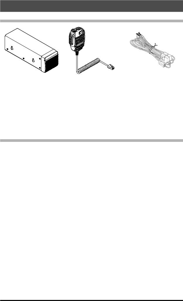
External Speaker SP-40 |
Hand Microphone SSM-75E |
DC Power Cord |
|
Spare Fuse (25A) |
|
|
|
• |
Operation Manual |
• World Map |
• Sticker |
|
Available options |
|
|
||
• |
Hand Microphone (equivalent to the supplied microphone) |
SSM-75E |
||
• |
Reference Microphone |
|
|
M-1 |
• |
Dual Element Microphone |
|
M-100 |
|
• |
Desktop Microphone |
|
|
M-90D |
• |
Microphone Stand Kit |
|
|
M-90MS |
• |
Desktop Microphone |
|
|
M-70D |
• |
Lightweight Stereo Headphone |
|
YH-77STA |
|
• |
External Automatic Antenna Tuner |
|
FC-40 |
|
• |
Active Tuning Antenna (Automatic Type) |
|
ATAS-120A |
|
• |
Antenna Base Kit (for ATAS-120A) |
|
ATBK-100 |
|
• |
Active Tuning Antenna (Manual Type) |
|
ATAS-25 |
|
• |
Remote Control Keypad |
|
|
FH-2 |
• |
LAN Unit |
|
|
SCU-LAN10 |
• |
Mounting Bracket |
|
|
SMB-209 |
• |
Carrying Handle |
|
|
MHG-1 |
• |
Packet Cable |
|
|
CT-39A |
• |
VL-1000 Linear Amplifier Connection Cable |
|
CT-58 |
|
8
Installation and Interconnections
Antenna Considerations
The FT-710 is designed to connect to a 50 Ohm resistive impedance antenna at the Amateur operating frequencies. Select an appropriate antenna (dipole antenna, YAGI antenna, cubical quad antenna, etc.) that is suitable for the chosen operation and bands.
Construct the antenna and coaxial cable, or use a suitable antenna tuner, to maintain the impedance presented to the FT-710 antenna connector for an SWR of 1.5 or less. Careful preparation of the antenna and/or tuner will permit maximum performance, and protect the transceiver from damage.
High transmitter RF voltages may be present on the antenna; install it so it will not be easily touched when in operation.
Antenna Connections
Carefully follow the illustration regarding the proper connection of antennas and coaxial cables.
To prevent damage from lightning, atmospheric electrical discharges, electric shock etc., provide a good earth ground.
Use a short, thick, braided cable to connect the station equipment to the buried ground rod (or alternative earth ground system).
Power Cable Connections
Carefully follow the illustrations regarding the proper connection of the DC power cable.
Use the DC power cable supplied with the FT-710 to make the power connections to the power supply.
Check the DC voltage and current rating
(+13.8 V, 25 A) of the power supply before connecting to the transceiver.
FUSE: 25A
RED |
BLACK |
DC power cord (supplied)
Installation guidelines
•Ensure adequate ventilation around the transceiver, to prevent heat build-up and possible reduction of performance due over heating.
•Do not install the transceiver in a mechanically unstable location, or where objects may fall onto it from above.
•To minimize the possibility of interference to home entertainment devices, take all precautionary steps including separation of TV/FM anten-
nas from Amateur transmitting antennas to the greatest extent possible. Keep the transmitting coaxial cables separated from cables connected to home entertainment devices.
•The AC Power Cord connected to a socket-out- let with earthing connection. A socket-outlet with earthing connection shall connect to protective earthing conductor.
9
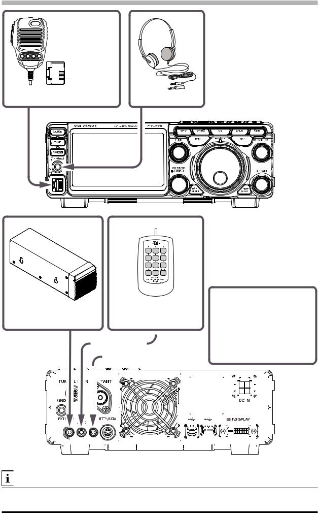
Microphone, Headphone, Key, Keyer and FH-2 Connections
DOWNUP
+5V
MIC GND
MIC


 PTT
PTT
GND
FAST
(as viewed from front panel) |
φ3.5mm |
External Speaker |
|
|
|
|
|
|
|
|
|
|
|
|
|
|
|
|
Remote Control Keypad |
|
|
|
|
|
|
|||||||||||||||||||||||||||||||||||||||||||||||||||||||||
SP-40 |
|
|
|
|
|
|
|
|
|
|
|
|
|
|
|
|
|
|
|
|
|
|
FH-2 (option) |
|
|
|
|
|
|
|||||||||||||||||||||||||||||||||||||||||||||||||||
|
|
|
|
|
|
|
|
|
|
|
|
|
|
|
|
|
|
|
|
|
|
|
|
|
|
|
|
|
|
|
|
|
|
|
|
|
|
|
|
|
|
|
|
|
|
|
|
|
|
|
|
|
|
|
|
|
|
|
|
|
|
|
|
|
|
|
|
|
|
|
|
|
|
|
|
|
|
|
|
|
|
|
|
|
|
|
|
|
|
|
|
|
|
|
|
|
|
|
|
|
|
|
|
|
|
|
|
|
|
|
|
|
|
|
|
|
|
|
|
|
|
|
|
|
|
|
|
|
|
|
|
|
|
|
|
|
|
|
|
|
|
|
|
|
|
|
|
|
|
|
|
|
|
|
|
|
|
|
|
|
|
|
|
|
|
|
|
|
|
|
|
|
|
|
|
|
|
|
|
|
|
|
|
|
|
|
|
|
|
|
|
|
|
|
|
|
|
|
|
|
|
|
|
|
|
|
|
|
|
|
|
|
|
|
|
|
|
|
|
|
|
|
|
|
|
|
|
|
|
|
|
|
|
|
|
|
|
|
|
|
|
|
|
|
|
|
|
|
|
|
|
|
|
|
|
|
|
|
|
|
|
|
|
|
|
|
|
|
|
|
|
|
|
|
|
|
|
|
|
|
|
|
|
|
|
|
|
|
|
|
|
|
|
|
|
|
|
|
|
|
|
|
|
|
|
|
|
|
|
|
|
|
|
|
|
|
|
|
|
|
|
|
|
|
|
|
|
|
|
|
|
|
|
|
|
|
|
|
|
|
|
|
|
|
|
|
|
|
|
|
|
|
|
|
|
|
|
|
|
|
|
|
|
|
|
|
|
|
|
|
|
|
|
|
|
|
|
|
|
|
|
|
|
|
|
|
|
|
|
|
|
|
|
|
|
|
|
|
|
|
|
|
|
|
|
|
|
|
|
|
|
|
|
|
|
|
|
|
|
|
|
|
|
|
|
|
|
|
|
|
|
|
|
|
|
|
|
|
|
|
|
|
|
|
|
|
|
|
|
|
|
|
|
|
|
|
|
|
|
|
|
|
|
|
|
|
|
|
|
|
|
|
|
|
|
|
|
|
|
|
|
|
|
|
|
|
|
|
|
|
|
|
|
|
|
|
|
|
|
|
|
|
|
|
|
|
|
|
|
|
|
|
|
|
|
|
|
|
|
|
|
|
|
|
|
|
|
|
|
|
|
|
|
|
|
|
|
|
|
|
|
|
|
|
|
|
|
|
|
|
|
|
|
|
|
|
|
|
|
|
|
|
|
|
|
|
|
|
|
|
|
|
|
|
|
|
|
|
|
|
|
|
|
|
|
|
|
|
|
|
|
|
|
|
|
|
|
|
|
|
|
|
|
|
|
|
|
|
|
|
|
|
|
|
|
|
|
|
|
|
|
|
|
|
|
|
|
|
|
|
|
|
|
|
|
|
|
|
|
|
|
|
|
|
|
|
|
|
|
|
|
|
|
|
|
|
|
|
|
|
|
|
|
|
|
|
|
|
|
|
|
|
|
|
|
|
|
|
|
|
|
|
|
|
|
|
|
|
|
|
|
|
|
|
|
|
|
|
|
|
|
|
|
|
|
|
|
|
|
|
|
|
|
|
|
|
|
|
|
|
|
|
|
|
|
|
|
|
|
|
|
|
|
|
|
|
|
|
|
|
|
|
|
|
|
|
|
|
|
|
|
|
|
|
|
|
|
|
|
|
|
|
|
|
|
|
|
|
|
|
|
|
|
|
|
|
|
|
|
|
|
|
|
|
|
|
|
|
|
|
|
|
|
|
|
|
|
|
|
|
|
|
|
|
|
|
|
|
|
|
|
|
|
|
|
|
|
|
|
|
|
|
|
|
|
|
|
|
|
|
|
|
|
|
|
|
|
|
|
|
|
|
|
|
|
|
|
|
|
|
|
|
|
|
|
|
|
|
|
|
|
|
|
|
|
|
|
|
|
|
|
|
|
|
|
|
|
|
|
|
|
|
|
|
|
|
|
|
|
|
|
|
|
|
|
|
|
|
|
|
|
|
|
|
|
|
|
|
|
|
|
|
|
|
|
|
|
|
|
|
|
|
|
|
|
|
|
|
|
|
|
|
|
|
|
|
|
|
|
|
|
|
|
|
|
|
|
|
|
|
|
|
|
|
|
|
|
|
|
|
|
|
|
|
|
|
|
|
|
|
|
|
|
|
|
|
|
|
|
|
|
|
|
|
|
|
|
|
|
|
|
|
|
|
|
|
|
|
|
|
|
|
|
|
|
|
|
|
|
|
|
|
|
|
|
|
|
|
|
|
|
|
|
|
|
|
|
|
|
|
|
|
|
|
|
|
|
|
|
|
|
|
|
|
|
|
|
|
|
|
|
|
|
|
|
|
|
|
|
|
|
|
|
|
|
|
|
|
|
|
|
|
|
|
|
|
|
|
|
|
|
|
|
|
|
|
|
|
|
|
|
|
|
|
|
|
|
|
|
|
|
|
|
|
|
|
|
|
|
|
|
|
|
|
|
|
|
|
|
|
|
|
|
|
|
|
|
|
|
|
|
|
|
|
|
|
|
|
|
|
|
|
|
|
|
|
|
|
|
|
|
|
|
|
|
|
|
|
|
|
|
|
|
|
|
|
|
|
|
|
|
|
|
|
|
|
|
|
|
|
|
|
|
|
|
|
|
|
|
|
|
|
|
|
|
|
|
|
|
|
|
|
|
|
|
|
|
|
|
|
|
|
|
|
|
|
|
|
|
|
|
|
|
|
|
|
|
|
|
|
|
|
|
|
|
|
|
|
|
|
|
|
|
|
|
|
|
|
|
|
|
|
|
|
|
|
|
|
|
|
|
|
|
|
|
|
|
|
|
|
|
|
|
|
|
|
|
|
|
|
|
|
|
|
|
|
|
|
|
|
|
|
|
|
|
|
|
|
|
|
|
|
|
|
|
|
|
|
|
|
|
|
|
|
|
|
|
|
|
|
|
|
|
|
|
|
|
|
|
|
|
|
|
|
|
|
|
|
|
|
|
|
|
|
|
|
|
|
|
|
|
|
|
|
|
|
|
|
|
|
|
|
|
|
|
|
|
|
|
|
|
|
|
|
|
|
|
|
|
|
|
|
|
|
|
|
|
|
|
|
|
|
|
|
|
|
|
|
|
|
|
|
|
|
|
|
|
|
|
|
|
|
|
|
|
|
|
|
|
|
|
|
|
|
|
|
|
|
|
|
|
|
|
|
|
|
|
|
|
|
|
|
|
|
|
|
|
|
|
|
|
|
|
|
|
|
|
|
|
|
|
|
|
|
|
|
|
|
|
|
|
|
|
|
|
|
|
|
|
|
|
|
|
|
|
|
|
|
|
|
|
|
|
|
|
|
|
|
|
|
|
|
|
|
|
|
|
|
|
|
|
|
|
|
|
|
|
|
|
|
|
|
|
|
|
|
|
|
|
|
|
|
|
|
|
|
|
|
|
|
|
|
|
|
|
|
|
|
|
|
|
|
|
|
|
|
|
|
|
|
|
|
|
|
|
|
|
|
|
|
|
|
|
|
|
|
|
|
|
|
|
|
|
|
|
|
|
|
|
|
|
|
|
|
|
|
|
|
|
|
|
|
|
|
|
|
|
|
|
|
|
|
|
|
|
|
|
|
|
|
|
|
|
|
|
|
|
|
|
|
|
|
|
|
|
|
|
|
|
|
|
|
|
|
|
|
|
|
|
|
|
|
|
|
|
|
|
|
|
|
|
|
|
|
|
|
|
|
|
|
|
|
|
|
|
|
|
|
|
|
|
|
|
|
|
|
|
|
|
|
|
|
|
|
|
|
|
|
|
|
|
|
|
|
|
|
|
|
|
|
|
|
|
|
|
|
|
|
|
|
|
|
|
|
|
|
|
|
|
|
|
|
|
|
|
|
|
|
|
|
|
|
|
|
|
|
|
|
|
|
|
|
|
|
|
|
|
|
|
|
|
|
|
|
|
|
|
|
|
|
|
|
|
|
|
|
|
|
|
|
|
|
|
|
|
|
|
|
|
|
|
|
|
|
|
|
|
|
|
|
|
|
|
|
|
|
|
|
|
|
|
|
|
|
|
|
|
|
|
|
|
|
|
|
|
|
|
|
|
|
|
|
|
|
|
|
|
|
|
|
|
|
|
|
|
|
|
|
|
|
|
|
|
|
|
|
|
|
|
|
|
|
|
|
|
|
|
|
|
|
|
|
|
|
|
|
|
|
|
|
|
|
|
|
|
|
|
|
|
|
|
|
|
|
|
|
|
|
|
|
|
|
|
|
|
|
|
|
|
|
|
|
|
|
|
|
|
|
|
|
|
|
|
|
|
|
|
|
|
|
|
|
|
|
|
|
|
|
|
|
|
|
|
|
|
|
|
|
|
|
|
|
|
|
|
|
|
|
|
|
|
|
|
|
|
|
|
|
|
|
|
|
|
|
|
|
|
|
|
|
|
|
|
|
|
|
|
|
|
|
|
|
|
|
|
|
|
|
|
|
|
|
|
|
|
|
|
|
|
|
|
|
|
|
|
|
|
|
|
|
|
|
|
|
|
|
|
|
|
|
|
|
|
|
|
|
|
|
|
|
|
|
|
|
|
|
|
|
|
|
|
|
|
|
|
|
|
|
|
|
|
|
|
|
|
|
|
|
|
|
|
|
|
|
|
|
|
|
|
|
|
|
|
|
|
|
|
|
|
|
|
|
|
|
|
|
|
|
|
|
|
|
|
|
|
|
|
|
|
|
|
|
|
|
|
|
|
|
|
|
|
|
|
|
|
|
|
|
|
|
|
|
|
|
|
|
|
|
|
|
|
|
|
|
|
|
|
|
|
|
|
|
|
|
|
|
|
|
|
|
|
|
|
|
|
|
|
|
|
|
|
|
|
|
|
|
|
|
|
|
|
|
|
|
|
|
|
|
|
|
|
|
|
|
|
|
|
|
|
|
|
|
|
|
|
|
|
|
|
|
|
|
|
|
|
|
|
|
|
|
|
|
|
|
|
|
|
|
|
|
|
|
|
|
|
|
|
|
|
|
|
|
|
|
|
|
|
|
|
|
|
|
|
|
|
|
|
|
|
|
|
|
|
|
|
|
|
|
|
|
|
|
|
|
|
|
|
|
|
|
|
|
|
|
|
|
|
|
|
|
|
|
|
|
|
|
|
|
|
|
|
|
|
|
|
|
|
|
|
|
|
|
|
|
|
|
|
|
|
|
|
|
|
|
|
|
|
|
|
|
|
|
|
|
|
|
|
|
|
|
|
|
|
|
|
|
|
|
|
|
|
|
|
|
|
|
|
|
|
|
|
|
|
|
|
|
|
|
|
|
|
|
|
|
|
|
|
|
|
|
|
|
|
|
|
|
|
|
|
|
|
|
|
|
|
|
|
|
|
|
|
|
|
|
|
|
|
|
|
|
|
|
|
|
|
|
|
|
|
|
|
|
|
|
|
|
|
|
|
Key-up voltage is approximately +5.0V DC, and key-down current is approximately 3mA.
10

Linear Amplifier Interconnections
Be sure that both the FT-710 and VL-1000 are turned OFF, and then follow the installation recommendations contained in the bellow illustration.
• VL-1000 Linear Amplifier Interconnections
• Refer to the VL-1000 Operating Manual for details regarding amplifier operation.
• Do not attempt to connect or disconnect coaxial cables when your hands are wet.
•Set the Setting Menu item “TUN/LIN PORT SELECT” to “LINEAR” (page 89).
•Since the ALC cable is connected to the REM/ALC jack, the optional FH-2 cannot be connected.
Coaxial Cable (50 ohm)
Connect to “INPUT 1” of the VL-1000
HF/50MHz Antenna
|
ANT |
<![if ! IE]> <![endif]>ANT 1 |
<![if ! IE]> <![endif]>ANT 2 |
<![if ! IE]> <![endif]>ANT 3 |
|
|
DC IN |
|
|
GND |
REM/ALC |
|
BAND-DATA 1 |
|
|
|
|
|
|
TUNER/LINEAR |
“CT-58” Band Data Cable (option) |
|
||
“CT-58” ALC Cable (option)
INPUT 1
ALC 1 |
GND |
|
|
|
DC 48V IN |
CONTROL
11
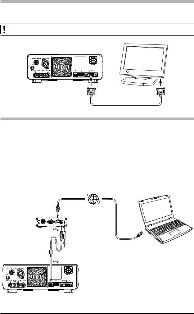
Display connections
The video digital output of the FT-710 transceiver can be shown on a large monitor. Use a commercially available DVI-D cable to connect a display monitor directly to the “EXT-DISPLAY” terminal (DVI-D) on the back of the FT-710.
The DVI-D cable can be used with either single link or dual link.
EXT-DISPLAY |
DVI-D |
DVI-D Cable |
|
Remote operation (LAN unit “SCU-LAN10”) connection
Operate the transceiver from a remote location. Use the optional LAN unit “SCU-LAN10” to connect the FT-710 to a LAN or the Internet, then use the PC control software that can be downloaded from the Yaesu website. In addition to the basic remote operation of the transceiver, the LAN unit supports monitoring the various scope displays, so you can operate comfortably. In addition to remote operation from a remote location, you can connect to your home LAN and monitor the band status on a large display from a convenient location away from the ham shack.
In addition to transmitted and received audio, the RF scope and AF scope can be remoted, so comfortable remote communication can be performed while easily setting and tuning the band status display, making various filter settings, interference removal function, etc. are possible using the scope function from a personal computer.
|
Internet |
|
|
or |
|
|
LAN Network |
Remote control PC |
Remote control |
|
|
SCU-LAN10 |
|
|
(option) |
LAN |
|
|
DC-IN |
LAN |
12
AESS (Acoustic Enhanced Speaker System)
The combination of the internal speaker on top of the transceiver with the external speaker “SP-40”, reproduces high-quality received audio with a wide frequency range and a three-dimensional acoustic effect. Set the optimum sound quality by adjusting the output balance and frequency characteristics of the two speakers according to your preference.
• The AESS is designed to function optimally with the included speaker “SP-40”. It will not perform properly with other speakers.
• When moving or transporting the FT-710, remove the SP-40 to prevent it from falling off.
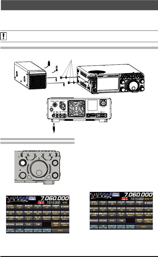
SP-40 connections
The SP-40 can be mounted on either the left or right side of the transceiver.
Supplied washers and screws
remove 
Connect the speaker cable to the
“EXT SPKR” terminal on the rear panel.
• Change the output balance of the |
• Change the frequency characteristics |
|||||||||||||||||||||||||
two speakers |
1. Press the [FUNC] knob. |
|||||||||||||||||||||||||
1. Press the [FUNC] knob. |
||||||||||||||||||||||||||
|
||||||||||||||||||||||||||
|
|
|
|
|
|
|
|
|
|
|
|
|
|
|
|
|
|
|
|
|
|
|
|
|
|
|
|
|
|
|
|
|
|
|
|
|
|
|
|
|
|
|
|
|
|
|
|
|
|
|
|
|
|
|
|
|
|
|
|
|
|
|
|
|
|
|
|
|
|
|
|
|
|
|
|
|
|
|
|
|
|
|
|
|
|
|
|
|
|
|
|
|
|
|
|
|
|
|
|
|
|
|
|
|
|
|
|
|
|
|
|
|
|
|
|
|
|
|
|
|
|
|
|
|
|
|
|
|
|
|
|
|
|
|
|
|
|
|
|
|
|
|
|
|
|
|
|
|
|
|
|
|
|
|
|
|
|
|
|
|
|
|
|
|
|
|
|
|
|
|
|
|
|
|
|
|
|
|
|
|
|
|
|
|
|
|
|
|
|
|
|
|
|
|
|
|
|
|
|
|
|
|
|
|
|
|
|
|
|
|
|
|
|
|
|
FUNC knob
2. Touch [AESS].
3.Rotate the [FUNC] knob to adjust the output balance of the two speakers, according to your liking. It is recommended to use it at around 50%.
FUNC knob
2. Touch [AESS-CF].
3.Rotate the [FUNC] knob to select the cutoff frequency from “700Hz” and “1000Hz”. Normally, 700Hz is a balanced sound quality, but when listening at a loud volume, set it to 1000Hz.
13
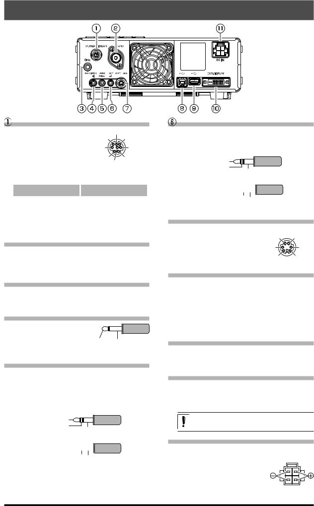
Rear Panel
TUNER/LINEAR
This 8-pin output |
RESET BAND D |
|
jack is used to con- |
TX INH |
BAND C |
nect to the FC-40 |
RX D(BAND B) |
GND |
External Automatic |
TX GND |
+13V OUT |
Antenna Tuner or a |
||
Linear Amplifier. |
TX D(BAND A) |
|
|
|
|
Refer to the table below for the BAND DATA terminal levels when using a linear amplifier.
BAND |
|
BAND DATA |
|
|
BAND |
|
BAND DATA |
|
||||
A |
B |
C |
|
D |
|
A |
B |
C |
|
D |
||
|
|
|
|
|
||||||||
400k |
H |
L |
H |
|
H |
|
18 |
L |
H |
H |
|
L |
1 |
L |
H |
H |
|
H |
|
21 |
H |
H |
H |
|
L |
1.8 |
H |
L |
L |
|
L |
|
24.5 |
L |
L |
L |
|
H |
3.5 |
L |
H |
L |
|
L |
|
28 |
H |
L |
L |
|
H |
5 / 7 |
H |
H |
L |
|
L |
|
50 |
L |
H |
L |
|
H |
10 |
L |
L |
H |
|
H |
|
70 |
H |
H |
H |
|
H |
14 |
H |
L |
H |
|
L |
|
|
|
|
|
|
|
 ANT
ANT
Connect the main antenna here, using type-M (PL259) connectors and coaxial feed lines. The internal antenna tuner affects only the antenna connected here, and only during transmission.
 GND
GND
Use this terminal to connect the transceiver to a good earth ground, for safety and optimal performance.
 EXT SPKR
This 3.5-mm, 2-contact, jack provides audio output for a
external loudspeaker “SP- SIGNAL GND 40”. The impedance at the
jack is 4-8 Ohms.
 REM/ALC
By plugging the FH-2 Remote Control Keypad into this jack, direct access to the FT-710 CPU is provided for control functions of the contest memory keying, and also frequency and function control. When a device such as a linear amplifier is connected, this is an external ALC current input jack.
EXT ALC |
|
TX REQ |
GND |
|
KEY
This 3.5-mm, 3-contact jack accepts a CW key or keyer paddle. A two-contact plug cannot be used in this jack. Key-up voltage is +5.0V DC, and keydown current is 3mA.
KEY |
|
NC |
GND |
|
|
When connecting a single straight key |
|
DOT


DASH
 COMMON
When connecting an electronic keyer paddle
 RTTY/DATA
This 6-pin input/output jack accepts AFSK input
from a Terminal Node |
DATA IN |
GND |
Controller (TNC); it also |
PTT |
SHIFT |
provides fixed level receiv- |
||
er audio output, and FSK |
DATA OUT |
SQL |
keying line. |
|
|
 USB
USB
Connecting to a computer from this jack with a commercially available USB cable allows remote control by CAT commands from a computer. The jack can also be used for input and output of audio signals and transmitter control. A USB driver is required for remote control from a computer. Download the driver from the Yaesu website (http://www. yaesu.com).
 USB Jack
Connect a USB A type keyboard or mouse. They can be used to select items on the screen or to enter characters.
 EXT-DISPLAY
DVI-D connector for connecting an external monitor.
When using an external monitor, set the setting menu item “EXT DISPLAY” to “ON”.
Connect a monitor that supports 800 x 480 resolution or 800 x 600 resolution.
Set menu item “TUN/LIN PORT SELECT” to “LINEAR”.
REMOTE


NC
 GND
GND
Set menu item “TUN/LIN PORT SELECT” to other than “LINEAR”.
 DC IN
DC IN
This is the DC power supply connection for the transceiver.
Use the supplied DC cable to connect directly to a DC power supply, which must be capable of supplying at least 25 A @13.8 VDC.
14
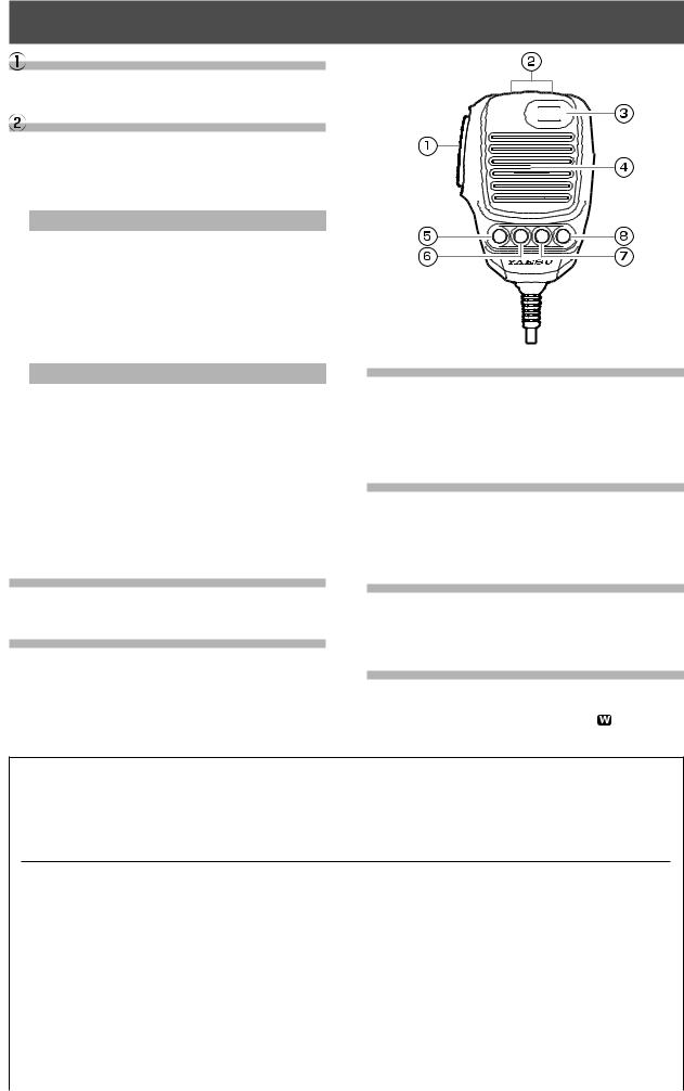
SSM-75E Microphone Switches
PTT Switch
Switches Transmit/Receive.
Press to transmit and release to receive.
DWN / UP Key
The [UP]/[DWN] keys may also be used to manually scan the frequency upward or downward.
●The amount of frequency change depends on the operation mode (default setting: see table below).
Operating Mode |
UP |
DWN |
|
LSB / USB / CW-L / CW-U |
+20Hz |
-20Hz |
|
|
|
|
|
DATA-L / DATA-U |
+10Hz |
-10Hz |
|
RTTY-L / RTTY-U / PSK |
|||
|
|
||
AM / AM-N / FM / FM-N |
+5kHz |
-5kHz |
|
DATA-FM / D-FM-N |
|||
|
|
 MUTE
MUTE

P1 |
P2 |
P3 |
P4 |
●The frequency change can be changed in the setting menu.
Operating Mode |
Menu Item |
Step |
LSB / USB |
SSB/CW DIAL STEP |
|
CW-L / CW-U |
|
|
|
|
|
DATA-L / DATA-U |
|
5/10/20 (Hz) |
RTTY-L / RTTY-U |
RTTY/PSK DIAL STEP |
|
PSK |
|
|
|
|
2.5/5/9/10/ |
AM / AM-N |
AM CH STEP |
12.5/25 |
|
|
(kHz) |
FM / FM-N |
|
5/6.25/10/ |
DATA-FM |
FM CH STEP |
12.5/20/25 |
D-FM-N |
|
(kHz) |
 MUTE Key
While pressing the MUTE key, the receiver audio from the speaker will be muted.
 Microphone
Speak into the microphone in a normal tone of voice with the microphone 5cm away from the mouth.
 P1 key
This key toggles the ON/OFF lock for the MAIN Dial knob. When “Lock” is ON, the MAIN Dial knob can still be turned, but the frequency will not change, and “LOCK” appears in the display.
It is the same function as the [LOCK] key on the front panel of the transceiver.
 P2 key
The current operation status can be stored in a dedicated memory channel (QMB: Quick Memory Bank) with one touch.
It is the same function as the [QMB] key on the front panel of the transceiver.
 P3 key
Pressing this key momentarily, exchanges the VFO-A and VFO-B frequency data.
It is the same function as the [A/B] key on the front panel of the transceiver.
 P4 key
This key toggles frequency control between VFO and the memory system.
It is the same function as the [V/M ] key on the front panel of the transceiver.
The functions of the [P1] / [P2] / [P3] / [P4] / [UP] / [DWN] keys can be assigned by the following operations:
1.Press the [FUNC] knob.
2.Select [OPERATION SETTING] → [GENERAL].
3.Select a key to assign a function [MIC P1]/[MIC P2]/[MIC P3]/[MIC P4]/[MIC UP]/[MIC DOWN].
4.Rotate the [FUNC] knob, or touch “<” or “>” on either side of the value to select a function (see the table below).
5.Touch [BACK] several times to return to normal operation.
LOCK |
: Toggles the ON/OFF lock for the MAIN |
|
FINE |
: Sets the fine tuning ON/OFF. |
|
||||
|
Dial knob. |
|
NAR |
: Sets the Narrow ON/OFF. |
QMB |
: QMB (Quick Memory Bank) function. |
|
NB |
: Activates the NB (Noise blanker) func- |
A/B |
: Swaps the VFO-A and VFO-B frequency |
|
|
tion. |
|
data. |
|
DNR |
: Activates the DNR (Digital Noise Reduc- |
V/M |
: Toggles frequency control between VFO |
|
|
tion) function. |
|
and the memory system. |
|
FREQ UP |
: Change to a higher frequency. |
TUNER |
: Turns the built-in antenna tuner ON/OFF. |
|
FREQ DOWN : Change to a Lower frequency. |
|
|
: Press to turn the VOX function ON/OFF. |
|
BAND UP |
: Change to a higher Operation Band. |
VOX/MOX |
Press and hold to activate the MOX |
|
BAND DOWN : Change to a Lower Operation Band. |
|
|
function. |
|
ATT |
: Turns the ATT (Attenuator) ON/OFF. |
|
: Change the operation mode. |
|
IPO |
: Activates the IPO. |
MODE |
: Press to activate the auto-zero function. |
|
DNF |
: Turns the DNF (Digital Notch Filter) ON/ |
ZIN SPOT |
Press and hold to activate the sidetone. |
|
|
OFF. |
SPLIT |
: SPLIT function. |
|
AGC |
: Adjust the AGC receiver-recovery time. |
|
|
|
|
|
|
|
|
|
|
15
Display Indications
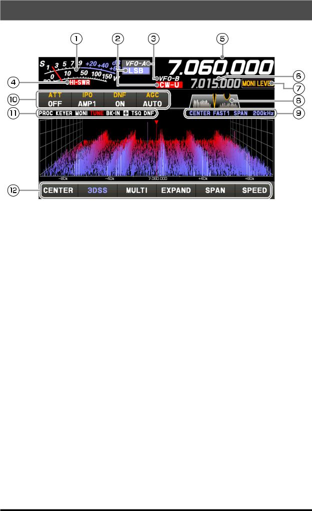
 It operates as an S meter in receive. In transmit, select the desired meter from: PO, COMP, ALC, VDD, ID, and SWR.
 Displays the current operation mode.
 In VFO mode, “VFO-A” or “VFO-B” is displayed. In memory mode, the type and channel number of the recalled memory are displayed.
 This display warns of an abnormality in the antenna system. If it lights up, check the antenna system immediately.
 Displays the transmit/receive frequency of Main-band.
 Displays the transmit/receive frequency of Sub-band. While the clarifier function is operating, the offset (difference between the receive frequency and the transmit frequency) is displayed.
 The functions that operate when the [FUNC] knob is turned are displayed.
 Displays the passband status of the Digital filter.
 Displays the mode, the sweep speed, and span width (display range) of the scope screen.
 Displays the setting status of assorted important receiver operations. The setting can be changed by touching it.
 The icon of the operating function lights up.
 Touch the scope screen keys to switch the display mode of the screen between the 3DSS display and waterfall display, to display the oscilloscope and AF-FFT, to switch the display area of the scope screen, to set the frequency span (display range), or to switch the sweep speed.
16
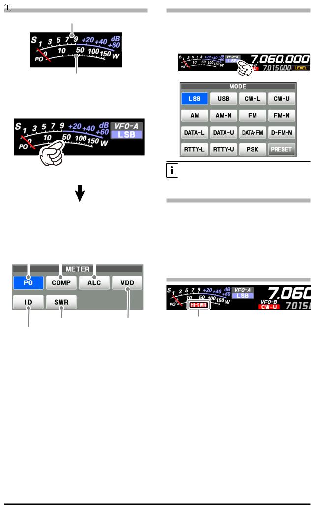
Meter Display
S-Meter
RF power Output
When the meter display screen is touched, the transmit meter selection screen is shown (the default setting is “PO”).
 Operation MODE Display
Displays the current operating mode. When touched the operation mode selection screen is displayed. Touch the desired operation mode to select it.
Touch the meter area |
Touch [PRESET] to display the settings that ap- |
ply to the FT8 operation. |
|
|
|
AMC gain control display (Displays compression level during speech processor operation)
Make adjustments by pressing the [FUNC] knob → → touch [COMP] → rotate the [FUNC] knob.
RF power Output |
Relative ALC voltage |
||
|
|
|
|
 Operation status Display
VFO-A: Lights in VFO-A mode. VFO-B: Lights in VFO-B mode.
M-xx: Displays the selected channel number in memory mode.
MT: Lights up during memory tuning operation. QMBxx: Lights up during operation with quick memory. M-Pxx: Lights up during programmable memory scan
operation.
EMG: Emergency call set frequency call lights up.
 HI-SWR Display
Standing Wave Ratio |
Final amplifier |
Final amplifier drain current |
drain voltage |
This is a warning notification of an abnormality in the antenna system.
If “HI-SWR” lights up, immediately check if for any abnormality in the antenna system.
17
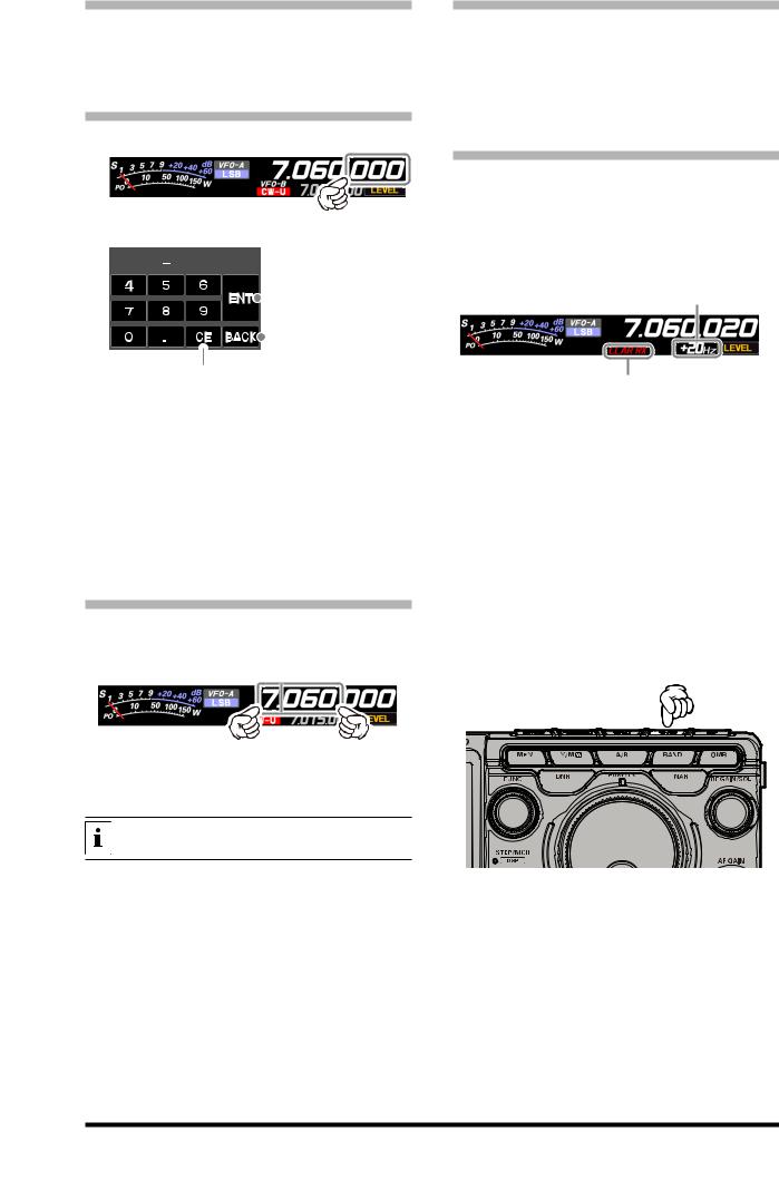
 Frequency Display (VFO-A)
Displays the transmit and receive frequencies of VFO-A. Press the [A/B] key to switch between VFO-A and VFO-B, the frequency of VFO-B is displayed.
• Keyboard Frequency Entry
1.Touch the “Hz” area of the frequency display.
2.Enter the frequency using the numeric keys.


 Erases the rightmost digit.
The entered frequency is
 confirmed.
The display returns to the  previous screen when
 back is touched. Clear all entered numbers.
●If there is no operation within 10 seconds, the input will be canceled.
3.Touch [ENT] to confirm.
●A short-cut for frequencies ending in zero - touch [ENT] after the last non-zero digit.
Example:
To enter 7.00.000MHz
[0]→[7]→[ENT] or [7]→[.]→[ENT]
To enter 7.03.000MHz
[7]→[.]→[0]→[3]→[ENT]
• Tuning in 1 MHz or 1 kHz Steps
To temporarily set the dial knob to 1MHz or 1kHz steps, touch the “MHz” or “kHz” area of the frequency display.
Touch “MHz” or “kHz” area of the frequency display to confirm. If there is no operation within 3 seconds, the frequency will be fixed.
Touch the Scope Screen, to easily move to the touched frequency.
 Frequency Display (VFO-B)
Displays the transmit and receive frequencies of VFO-B. Press the [A/B] key to switch between VFO-B and VFO-A, the frequency of VFO-A is displayed.
When the clarifier function is active, the offset frequency is displayed.
• When the clarifier function is active
The clarifier is used to adjust the transceiver receive frequency to match the other station transmit frequency and improve the audio; or to shift the transmit frequency of this station when the transmit frequency of the contact station is shifted.
When the receive frequency is offset by +20 Hz.
CLAR RX Changes only the receive frequency while leaving the transmit frequency as it is.
CLAR TX Changes only the transmit frequency while leaving the receive frequency as it is.
CLAR RXTX • After changing the receive frequency with the clarifier, pressing the [CLAR] key twice will set the transmit frequency to match the receive frequency.
•After changing the transmit frequency with the clarifier, pressing the [CLAR] key will set the receive frequency to match the transmit frequency.
Press the [CLAR] key, the display will show “CLAR
RX” in red and the clarifier will be active.
Rotate the DIAL knob to change the offset frequency of the clarifier.
To cancel Clarifier operation, press the [CLAR] key several times.
18
 Operation of the display [FUNC] knob
Displays the multiple functions that may be operated when the [FUNC] knob is pressed. Normally, it is recommended to adjust the level of the spectrum scope with the [LEVEL] knob.
The last used function is recalled when the [FUNC] knob is pressed. Therefor you can easily call up and then set a function by turning the [FUNC] knob.
To change the function of the [FUNC] knob, touch the desired item that appears on the function screen when the [FUNC] knob is pressed, or turn the [FUNC] knob to select an item and then press the [FUNC] knob.
Operation of the FUNC knob
FUNC knob |
The following settings and operations can be performed with the [FUNC] control.
LEVEL |
: Adjust the reference level to make it easier to distinguish the scope display target signal |
PEAK |
from the noise. |
: Adjust the Peak Signal Color Density. |
|
MARKER |
: ON/OFF Marker indicates the transmit and receive frequency position within the Scope |
COLOR |
Display image. |
: Changes the scope display color. |
|
CONTRAST |
: Adjust the contrast of the TFT display. |
DIMMER |
: Adjust the brightness of the TFT display. |
M-GROUP |
: Memory group selection. |
MIC GAIN |
: Adjusts the microphone gain. |
MIC EQ |
: Three-Band Parametric Microphone Equalizer is turned ON/OFF. |
PROC LEVEL |
: Adjusts the Speech Processor Gain. |
AMC LEVEL |
: Adjusts the AMC (Automatic Microphone Gain Control) Gain. |
VOX GAIN |
: VOX gain setting. |
VOX DELAY |
: VOX delay setting. |
ANTI VOX |
: Anti-VOX Settings. |
RF POWER |
: Transmit power setting. |
MONI LEVEL |
: Monitor level adjustment. |
KEYER |
: Built-in electronic keyer is turned ON/OFF. |
BK-IN |
: CW Break-in function is turned ON/OFF. |
CW SPEED |
: Adjusts the desired sending speed. |
CW PITCH |
: Adjusts the CW tone when receiving the CW signal and the side tone monitor. |
BK-DELAY |
: Adjust the hang time after the CW transmitting ends. |
AESS |
: Change the output balance of the two speakers. |
AESS-CF |
: Change the frequency characteristics. |
19
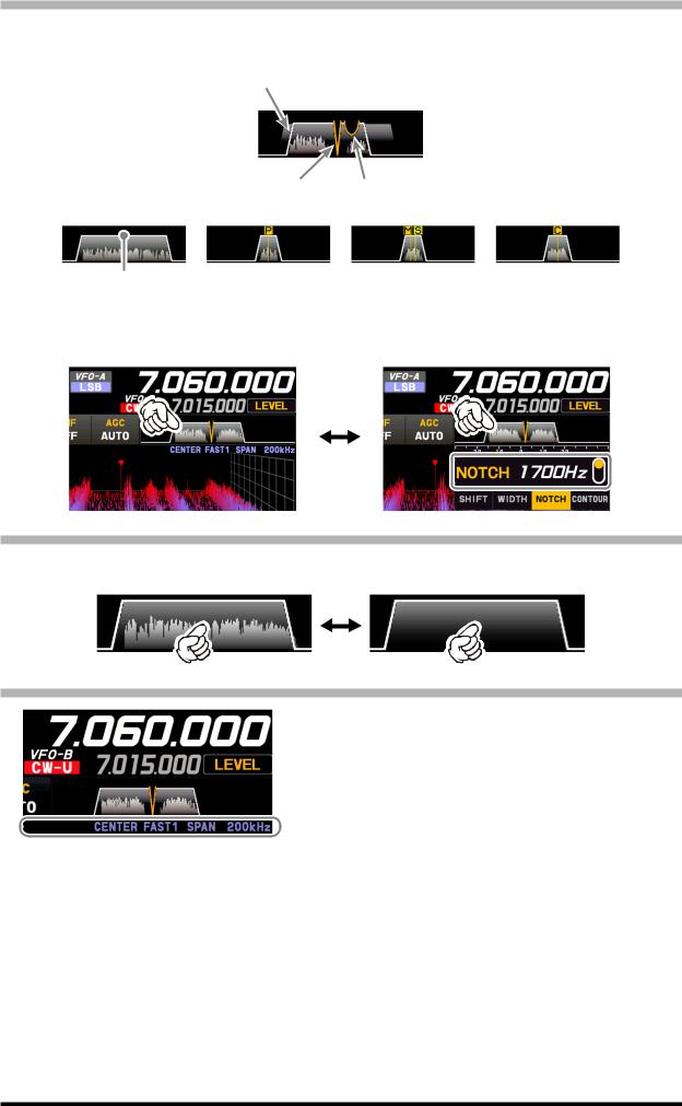
 Filter Function Display
Displays the passband status of the Digital filter. The operation of WIDTH, SHIFT, NOTCH, CONTOUR etc. can be observed.
Passband status of DSP filter (SHIFT, WIDTH)
State of NOTCH State of CONTOUR
SSB Mode |
CW Mode |
RTTY Mode |
PSK/DATA Mode |
DSP filter bandwidth
Touch the filter display to reveal and check the setting value of the last used function from SHIFT, WIDTH, NOTCH,
CONTOUR, and APF. The setting may be changed by turning the [FUNC] knob of the active function.
Example: When the last function used is the NOTCH function
Touch the filter display to display the NOTCH function setting value.
• Turn the spectrum display OFF
To display only the Digital filter bandwidth information, press and hold the spectrum area of the filter function display to clear the spectrum view. To display it, press and hold again.
 Information displayed on the scope screen
CENTER : The receive frequency is always shown at the
|
|
center of the screen and spectrum display. |
||
|
|
The band spectrum is shown within the range |
||
|
|
set by “SPAN”. The CENTER mode is conve- |
||
|
|
nient for monitoring the signal activity around |
||
|
|
the operating frequency. |
||
|
CURSOR: Monitors the spectrum within the range set |
|||
|
|
with “SPAN”. When the frequency (marker) |
||
|
|
|||
|
|
exceeds the upper limit or the lower limit of |
||
Scope screen information |
||||
the range, the screen is automatically scrolled |
||||
|
|
|||
|
|
and the status beyond the setting range can |
||
|
FIX |
be observed. |
|
|
|
: Enter the start frequency of the scope. |
|||
|
SLOW1 |
: sweep speed |
Slow |
|
|
SLOW2 |
: sweep speed |
↑ |
|
|
FAST1 |
: sweep speed |
Normal |
|
|
FAST2 |
: sweep speed |
↓ |
|
|
FAST3 |
: sweep speed |
Fast |
|
|
STOP |
: Temporarily hold the operation of DSS dis- |
||
play and waterfall display.
SPAN nnnkHz : Scope Screen frequency span (display range).
20
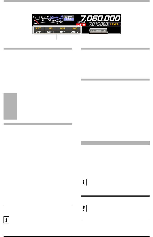
 Important Receiver Settings
The status of various operations that are important during receive, are shown at the bottom of the display. To change a setting, touch the appropriate location on the display.
Important setting items when receiving
• ATT (Attenuator)
Displays the current ATT (Amount of receive input signal attenuation).
When the desired signal is extremely strong or the noise level is high on a low frequency band, activate the attenuator to reduce the incoming signal or noise from the antenna.
After touching [ATT], touch the desired attenuation amount.
The attenuator is set independently for each operation band.
OFF |
Attenuator is Off |
|
6dB |
The incoming signal power is reduced by 6dB |
|
(Signal voltage reduced to 1/2) |
||
|
||
12dB |
The incoming signal power is reduced by 12dB |
|
(Signal voltage reduced to 1/4) |
||
|
||
18dB |
The incoming signal power is reduced by 18dB |
|
(Signal voltage reduced to 1/8) |
||
|
• IPO
The IPO (Intercept Point Optimization) function can establish the gain of the RF amplifier section to accommodate the connected antenna and the received signal conditions. IPO can be selected from three operating conditions.
AMP1: One stage RF amplifier is connected. This is a well-balanced operation of receiver sensitivity and characteristics (Approximately 10 dB gain).
AMP2: Two RF amplifiers are connected in series to give top priority to sensitivity (Approximately 20 dB gain).
IPO: The received signal is input to the IF mixer without passing through the RF amplifier. This can greatly improve receiving, especially in the harsh low band signal environment.
After touching [IPO], touch the desired operating condition.
•IPO is set independently for each operation band.
•Normally, select “AMP1”.
•The IPO can not only attenuate the input signal but also improve the intermodulation characteristics. It is most effective to operate the IPO first, and then use the ATT if the signal is still too strong. The noise level can be attenuated and S/N greatly improved.
• DNF (Digital NOTCH Filter)
The Digital NOTCH Filter (DNF) is an effective beat-canceling filter that can null out a number of interfering beat notes inside the receiver passband.
Because this is an Auto-Notch feature, there is no djustment knob associated with this filter.
• AGC (Automatic Gain Control)
Displays the currently selected AGC setting.
The AGC system is designed to help compensate for fading and other propagation effects. The
AGC characteristics can be individually set for each operating mode. The basic objective of AGC is to maintain a constant audio output level once a certain minimum threshold of signal strength is achieved.
After touching [AGC], touch the desired time constant.
●AGC can be set for each operation band.
●The “AUTO” selection mode selects the optimum receiver-recovery time for the reception mode.
Operating Mode |
AUTO AGC Selection |
|
LSB / USB / AM / AM-N |
SLOW |
|
|
|
|
CW-L / CW-U / FM / FM-N |
FAST |
|
DATA-FM / D-FM-N |
||
|
||
|
|
|
RTTY-L / RTTY-U |
MID |
|
DATA-L / DATA-U / PSK |
||
|
||
|
|
|
|
|
Normally, AGC is set to “AUTO”, which automatically selects the time constant according to the received signal type, but when receiving a weak signal or when there is noise and fading, the AGC action may be changed according to the reception condition at that time. Change the time constant to make received signals most audible
Several aspects of AGC performance may be configured via the Menu. However, because AGC can have such a profound impact on overall receiver performance, we generally do not recommend any changes to the AGC Menu selections until you are thoroughly familiar with the performance of the FT-710.
21
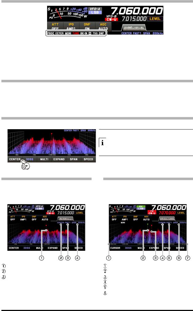
 Information displayed on the scope screen
PROC |
: Lights when the Speech function is activated. |
+/ : Lights in plus (+) or negative (-) shift (repeater |
KEYER : Lights when the Built-in electronic keyer is |
operation). |
|
|
activated. |
ENC : Lights when the tone encoder is operating. |
MONI |
: Lights when the MONITOR function is activated. |
TSQ : Lights during tone squelch operation. |
TUNE |
: Lights when the internal Automatic Antenna |
DNF : Lights when the DNF (Digital Notch Filter) is |
BK-IN |
Tuner is activated. Blinks during tuning. |
activated. |
: Lights when the CW Break-in function is activated. |
|
|
 Scope Display Setting
In addition to the conventional two-dimensional waterfall spectrum display, Yaesu has added the 3-Dimen- sion Spectrum Stream (3DSS) color display. The constantly changing band conditions and signals are depicted in real time and color. The frequency span is shown on the horizontal X axis, the vertical Y axis depicts the signals and their strengths, and the time is represented on the receding Z axis. The FT-710 operator can intuitively grasp the band and signal conditions at any instant.
• CENTER/CURSOR/FIX
Switches the Spectrum Scope operation each time the key is touched.
• When the display area is touched, the receive frequency is moved to that point.
• In CENTER mode, the frequency touched becomes the center.
• In CURSOR and FIX mode, the marker and the receive frequency move to the touched position.
• CENTER
The receive frequency is always shown at the center of the screen and spectrum display. The band spectrum is shown within the range set by “SPAN”. The CENTER mode is convenient for monitoring the signal activity around the operating frequency.
Marker*
Current display mode (CENTER) Sweep Speed
 Scope Screen frequency span (display range).
*At factory shipment, marker display is ON.
• CURSOR
Monitors the spectrum within the range set with “SPAN”. When the frequency (marker) exceeds the upper limit or the lower limit of the range, the screen is automatically scrolled and the status beyond the setting range can be observed.
The lower limit frequency of the display area. Marker* (Receive Frequency)
Marker* (Transmit Frequency) Current display mode (CURSOR) Sweep Speed
Scope Screen frequency span (display range).  The upper limit frequency of the display area.
*At factory shipment, marker display is ON.
22
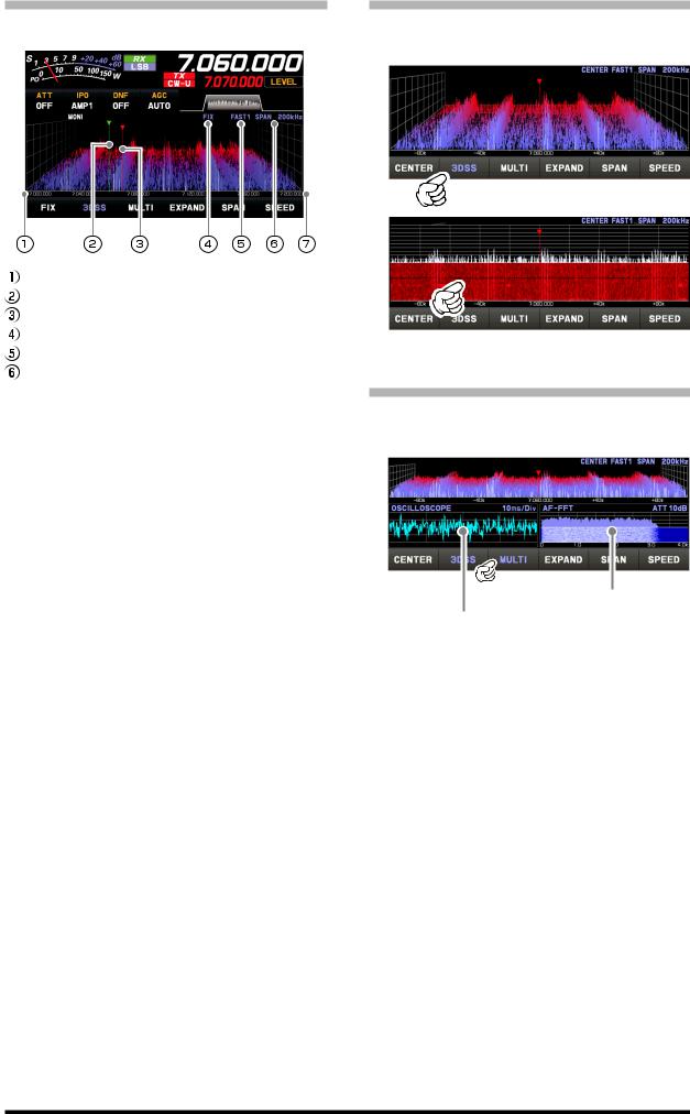
• FIX
To use Fixed Mode, enter the start frequency of the scope.
Display area start frequency Marker* (Reception Frequency) Marker* (Transmit Frequency) Current display mode (FIX) Sweep Speed
Scope Screen frequency span (display range).  The upper limit frequency of the display area.
*At factory shipment, marker display is ON.
FIX is displayed at the top of the scope screen. Press and hold [FIX] while FIX is displayed, the frequency input screen will be displayed, and the start frequency can be entered:
Example:
To enter 7.000.000 MHz
[0]→[7]→[ENT] or [7]→[.]→[ENT]
To enter 7.030.000 MHz
[7]→[.]→[0]→[3]→[ENT]
• 3DSS
Switch between the 3DSS display and the waterfall display.
The display will change each time it is touched:
3DSS type
Waterfall type
• MULTI
In addition to the scope display, the oscilloscope and AF-FFT are also presented.
Touch again to return to the original screen.
this area to set the attenuator. Touch this area to set the level and sweep speed.
23
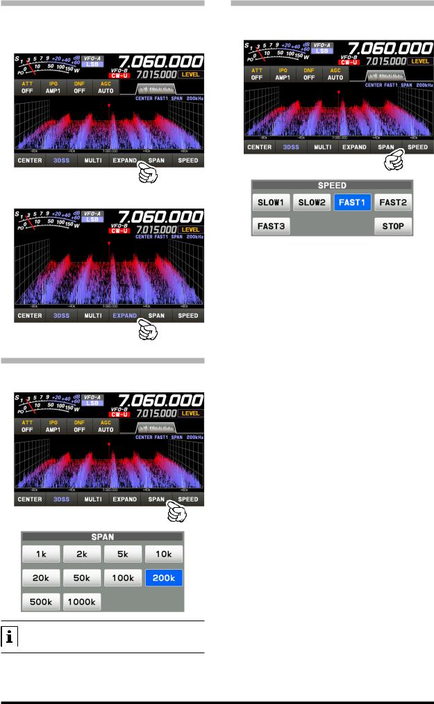
• EXPAND
The display area of the scope screen may be expanded vertically.
Touch to expand the display. Touch again to return to the original.
Normal Display
Larger View
• SPAN
Set the frequency span (display range) of the scope screen. After touching, select the desired span.
The display level changes when SPAN is changed, so reset the optimum display level with [LEVEL] each time.
• SPEED
Sets the Scope Display sweep speed. After touching, select the desired speed.
SLOW1 |
: sweep speed |
Slow |
SLOW2 |
: sweep speed |
↑ |
FAST1 |
: sweep speed |
Normal |
FAST2 |
: sweep speed |
↓ |
FAST3 |
: sweep speed |
Fast |
STOP |
: Touch [STOP] to temporarily hold the |
|
|
3DSS display and waterfall display op- |
|
|
erations. Touch [STOP] again or another |
|
|
speed, to release the hold. |
|
24
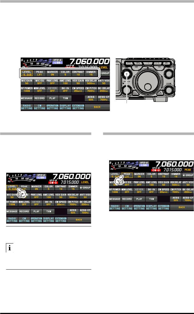
Set with the FUNC knob
Operate the [FUNC] knob to make the following settings related to the display.
LEVEL : Adjust the LEVEL of the scope for the best image on the screen.
PEAK : Adjust the color density with respect to the signal level on the scope screen in 5 steps (LV1 to LV5).
MARKER : ON/OFF Marker indicates the transmit and receive frequency position within the Scope Display image.
COLOR : Changes the scope screen display color from 11 types.
CONTRAST : Adjust the TFT display contrast (difference between light and dark) in 21 steps.
DIMMER : Adjust the TFT display brightness in 21 steps.
FUNC knob |
The last function used is retained in the [FUNC] knob so it can be easily set by operating the [FUNC] knob. Normally, it is suggested to utilize the [FUNC] knob as the [LEVEL] knob for the spectrum scope.
• LEVEL |
• PEAK |
Adjust the level to make it easier to distinguish between the desired signal and noise. The display level changes depending on antenna gain, condition, frequency band, SPAN and so on.
Always adjust the LEVEL for the best image on the screen.
Press the [FUNC] knob then touch [LEVEL], and then turn the [FUNC] knob to select the desired level.
The color density may be adjusted to the level of the signal. Touch PEAK and then select the desired color concentration.
Press the [FUNC] knob then touch [PEAK], and then turn the [FUNC] knob to select the desired level.
•On the 3DSS screen, weak signals may be more easily observed by adjusting the LEVEL so that the noise level can be seen only a little, so always adjust the LEVEL and use it at the optimum position.
•Be sure to make adjustments when changing bands or changing SPAN.
•If the level is changed, the signal strength also appears to change, but it does not affect the actual signal input level.
LV1 : |
Thin |
LV2 : |
↑ |
LV3 : |
Normal |
LV4 : |
↓ |
LV5 : |
Dark |
25

• MARKER
Displays markers that indicates the position of the current receive and the transmit frequencies in the spectrum.
Press the [FUNC] knob then touch [MARKER] to turn the MARKER ON or OFF. Normally leave it ON.
Receive Frequency Transmit Frequency
• COLOR
The display color of the scope screen can be changed.
Press the [FUNC] knob then touch [COLOR], then touch the desired color from the color selection screen.
The Display Color selection screen will disappear automatically after about 5 seconds.
• Adjust contrast
Adjust the contrast of the TFT display.
Press the [FUNC] knob then touch [CONTRAST], and then turn the [FUNC] knob to adjust the contrast.
• Adjusting the brightness (DIMMER)
Adjust the brightness of the TFT display.
Press the [FUNC] knob then touch [DIMMER], and then turn the [FUNC] knob to adjust the brightness.
26

Other display settings
• Screen Saver
A Screen saver, to prevent burning of the TFT screen will operate after a set time, if no transceiver function is operated.
1.Press the [FUNC] knob.
2.Touch [DISPLAY SETTING] or rotate the [FUNC] knob to select [DISPLAY SETTING] and then press the [FUNC] knob.
3 . To u c h [DISPLAY] → [SCREEN SAVER] or rotate the [FUNC] knob to select an item and press the [FUNC] knob.
4.Rotate the [FUNC] knob, or touch “<” or “>” on either side of the value to select the time until the screen saver is employed (default setting is 60 min).
• Inputting the Call Sign
Registered call signs names, and characters can be displayed on the opening screen when the power is turned ON.
1.Press the [FUNC] knob.
2.Touch [DISPLAY SETTING] or rotate the [FUNC] knob to select [DISPLAY SETTING] and then press the [FUNC] knob.
3.Touch [DISPLAY]→ [MY CALL] or rotate the [FUNC] knob to select the item and press the [FUNC] knob.
4.Touch a character key. The touched character will be displayed at the top of the screen. Enter each character of your call sign.
Up to 12 characters (letters, numbers, and symbols) can be entered.
OFF Screen saver is not employed.
15min Screen saver activates after 15 minutes.
30min Screen saver activates after 30 minutes.
60min Screen saver activates after 60 minutes.
5.Press the [FUNC] knob to save the new setting.
6.Touch [BACK] several times to return to normal operation.
Caps |
The input switches between lower and up- |
per-case letters each time this symbol is |
|
|
touched. |
|
One character to the left of the cursor is |
|
erased when this symbol is touched. |
BACK |
The display returns to the previous screen |
when this symbol is touched. |
27

/ |
The cursor in the input field moves left or |
|
right when these symbols are touched. |
||
|
Space Insert space
The entered characters are confirmed and ENT the display returns to the previous screen
when this symbol is touched.
5. Touch [ENT] to save the new setting and exit to normal operation.
About TFT Displays
FT-710 utilizes a TFT liquid-crystal display.
Although TFT liquid-crystal displays are made using very precise technology, they are prone to develop dead pixels (dark dot) or pixels that are always on (bright dot). Please understand that such phenomena do not constitute product defects or malfunctions. Rather, this phenomenon occurs due to limitations in the manufacturing technology with respect to TFT liquid-crystal displays.
•Depending on the viewing angle, unevenness in color or brightness may occur. Please note that any unevenness observed is inherent to the construction of TFT liquid crystal displays and therefore does not constitute a product defect or malfunction.
•If your TFT liquid-crystal display becomes dirty, please use a dry soft cloth or tissue to wipe the display clean. If it is extremely dirty, moisten it with water or lukewarm water and wipe it off with a soft cloth that has been wrung out tightly. Use of glass cleaner, household cleaners, organic solvents, alcohol, abrasives, and/or like substance may damage the TFT liquid-crystal display.
28
Loading...