


FT-991A
Table of contents
 Loading...
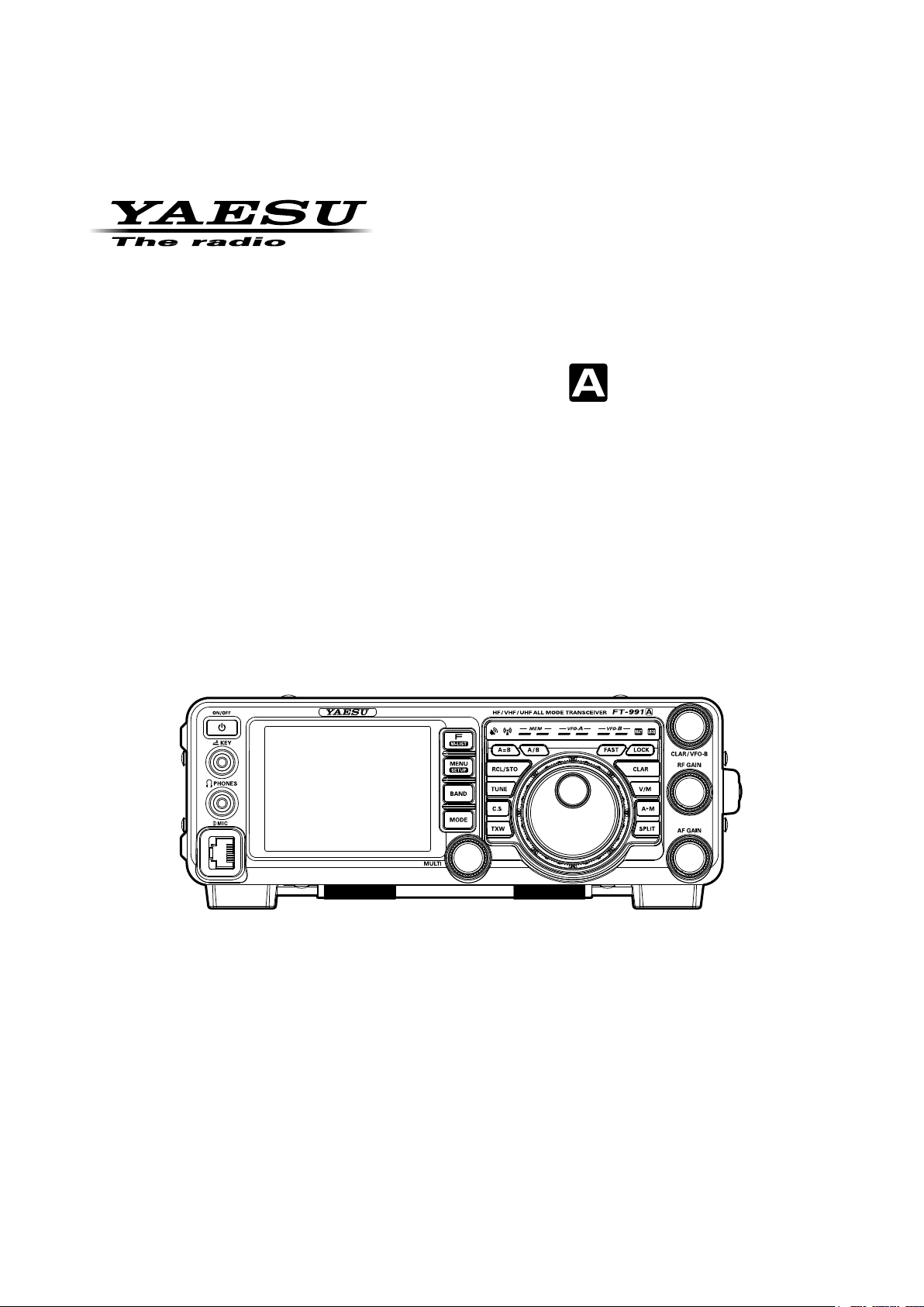
HF/VHF/UHF All Mode TrAnsceiVer
FT-991
operATing MAnUAl
YAESU MUSEN CO., LTD.
Tennozu Parkside Building
2-5-8 Higashi-Shinagawa, Shinagawa-ku, Tokyo 140-0002 Japan
YAESU USA
6125 Phyllis Drive, Cypress, CA 90630, U.S.A.
YAESU UK
Unit 12, Sun Valley Business Park, Winnall Close
Winchester, Hampshire, SO23 0LB, U.K.

About this MAnuAl . . .
The
FT-991A
iar to you. In order to gain the most enjoyment and operating efciency from your
read this manual in its entirety, and keep it handy for reference as you explore the many capabilities of your new transceiver.
Before using your
al.
FT-991A utilizes a TFT liquid-crystal display.
• Although TFT liquid-crystal displays are made using very precise technology, they are prone to develop
• Depending on the viewing angle, unevenness in color or brightness may occur. Please note that any uneven-
• If your TFT liquid-crystal display becomes dirty, please use a dry soft cloth or tissue to wipe the display
is a leading-edge transceiver with a number of new and exciting features, some of which may be unfamil-
FT-991A
FT-991A
dead pixels (dark dot) or pixels that are always on (bright dot). Please understand that such phenomena
do not constitute product defects or malfunctions. Rather, this phenomena occurs due to limitations in the
manufacturing technology with respect to TFT liquid-crystal displays.
ness observed is inherent to the construction of TFT liquid crystal displays and therefore does not constitute
a product defect or malfunction.
clean. Use of glass cleaner, household cleaners, organic solvents, alcohol, abrasives, and/or like substance
may damage the TFT liquid-crystal display.
, be sure to read and follow the instructions in the “Before You Begin” section of this manu-
About TFT Displays
, we recommend that you

general DescripTiOn
Built-in high-brightness TFT full-color
display with touch-panel functionality
The FT-991A is equipped with a 3.5 inch full-color TFT
display. Functions, including the receiving band, the noise
and signal interference reduction tools are graphically
displayed. Even while performing rigorous operations,
during DX pditions or contests, the operator may instantly
grasp the status of each function.
Equipped with C4FM digital mode
This transceiver C4FM mode provides good error correction performance, and supports the V/D mode (voice/
data simultaneous transmission mode) which makes the
transceiver suitable for mobile communication, and the
Voice FR mode (voice full rate mode) which allows the
transceiver to transmit high quality digital audio. The AMS
function recognizes the contacting stations transmission
method and automatically switches the transceiver to the
same C4FM digital or analog (FM) communications mode
as the received signal.
GM (Group Monitor) function allows
registering frequently communicating
stations to a memory group. The group
members may then automatically
exchange (send/receive) station location
information.
The transceiver automatically checks the channel frequency for registered member stations that are within communicating range. The distance and direction information
of the call sign members of the group may be shown on
the TFT display.
Comes equipped with two types of
roong lters
This transceiver is equipped with two types of roong lters for 3 kHz and 15 kHz bandwidths. These narrow band
lters are especially useful on a very crowded band during
contests, because they can dramatically attenuate powerful
out-of-band signals in the rst IF stage and reduce their
impact in the second stage to further optimizing the excel-
lent dynamic range and IP3 characteristics for processing
signals ranging from faint to powerful.
Two selectable RF ampliers provide the
optimal receiver gain for each low-to high
HF band (see page 48.
Congure the front end RF circuitry for the precise gain and
performance to suit the conditions of each HF band.Select
the IPO (Intercept Point Optimization) feature to optimize
the proximal multi-signal and mutual modulation characteristics in order to minimize the effects of powerful broadcast
stations, especially in the low-band so that even the faintest
signals can be received. When higher gain is advantageous,
select the single low noise RF amplier AMP1. In the high
bands, adding AMP2 provides maximum useful gain.
)
High stability built-in TCXO
The 30.225 MHz standard oscillator provides exceptional
frequency stability. It is temperature compensated and
boasts an enhanced ±0.5 ppm stability from −10°C to
+50°C.
WIDTH feature and continuously variable
bandwidth SHIFT feature. Optimal wide to
narrow bandwidth switching (see pages
51, 52.
The SHIFT feature, can eliminate interference in one side
of the passband. The WIDTH feature allows the bandwidth
to be narrowed by rotating the WIDTH knob. The moment
weak signals disappear due to interfering signals (including pile-ups), you can eliminate the interfering signals and
extract only the desired signal, thanks to the unique DSP
sharp ltering characteristic.
)
CONTOUR feature is renowned for
effective noise control (see page 50.
Rather than using the DSP extremely sharp attenuation
characteristics, the CONTOUR circuit provides gentle
shaping of the DSP passband lter and can thus attenuate
or peak bandwidth components in segments. The interfering signal can be naturally shaped without having part of
the signal suddenly interrupted. The contour function is
very effective in making the desired signal rise out of the
interference.
)
DNR (Digital Noise Reduction) by DSP
digital processing (see page 56.
The incorporated digital noise reduction circuit may be
set to the optimal working point by varying the 15 step
parameters according to the noise type.
)
NOTCH feature that significantly
eliminates unwanted beat signals; and
DNF feature that instantly attenuates
multiple beat signals (see page 56.
When interfering beat signals are present in the receiver
passband, the IF NOTCH feature can signicantly eliminate a part of the passband and remove the beat signal.
Moreover, the function is equipped with an Automatic
Tracking System DNF (Digital Notch Filter) that can
be engaged by DSP when there are multiple interfering
signals, even when the frequency is changing.
)
Reliable High-output Final Amplifier
Stage
In the HF/50MHz frequency range, a pair of RD100HHF1
transistors in a push-pull RF amplier arrangement deliv-
ers 100 watts of low-distortion, high-quality transmitter
power. The nal amplier for the 144 MHz/430 MHz
bands uses the high-output RDH70HUF2 device, provid-
ing ample output power of 50 watts.
T-991
OperaTing Manual
Page 1F

general DescripTiOn
Microphone Amplifier that includes
Parametric Equalizer (see page 65.
The microphone amplier equalizer feature is equipped
with a three-stage parametric equalizer that can alter the
Low, Mid, and High frequencies of the audio separately;
this feature permits the bandwidth and gain for each part of
the audio spectrum to be precisely adjusted independently.
Real-Time Spectrum Scope and Multi-Color
Waterfall Display (see page 42.
The spectrum scope function provides a visual display of
the strength and distribution of signals across the band in
real time. The Waterfall Display Mode portrays color differentiation between strong and weak signals.
)
)
High speed antenna tuner (see page 63.
The transceiver is equipped with the relay switching high
speed digital tuner which supports 1.8 MHz to 50 MHz.
The large 100-channel tuning data memory allows immediate recall of the optimum matching conditions for
previously tuned frequencies.
)
Optional Five Channel Message Memory
(
voice memory) (see page 70.
You can use the 5 channel voice memory function which
is useful for operating in contests, etc. This voice memory
enables recording of up to 20 seconds of audio for each
message you want to send.
Custom selection (C.S) button (see page 39.
This feature lets you select any Menu item for one-touch
access via the C.S button.
)
)
Page 2 F
T-991
OperaTing Manual

Table OF cOnTenTs
General Description ..................................................... 1
Table of Contents ......................................................... 3
Safety Precautions ........................................................ 5
Accessories & Options ................................................. 7
Supplied Accessories ................................................ 7
Available Options ..................................................... 8
Before You Begin .......................................................... 9
Base Station Wire Stand ........................................... 9
Adjusting the Main Tuning Dial Torque .................. 9
Adjusting the Clock ................................................ 10
Inputting the Call Sign ........................................... 11
Resetting the Microprocessor ................................. 12
Antenna Considerations ......................................... 13
About Coaxial Cable .............................................. 13
Grounding ............................................................... 14
Connection of Antenna and Power Cables ............. 15
Installation and Interconnections ............................. 16
Connection of Microphone, Headphone and
Remote Control Keypad ......................................... 16
Key, Keyer, and Computer-Driven Keying
Interconnections ..................................................... 17
VL-1000 Linear Amplier Interconnections .......... 18
Plug/Connector Pinout Diagrams ........................... 19
Front Panel Controls & Switches ............................. 20
About the Display ....................................................... 24
TFT Liquid Crystal Display ................................... 24
LED Indicators ....................................................... 26
Rear Panel ................................................................... 27
MH-31A8J Microphone Switches ............................. 29
Optional FH-2 Remote Control Switches ................ 30
Optional MH-36E8J Microphone Switches ............. 31
Basic Operation: Receiving on Amateur Bands ...... 32
Operation on 60-Meter (5 MHz) Band
(U.S. and U.K. version only) .................................. 35
CLAR (Clarier) Operation ................................... 36
LOCK ..................................................................... 37
DIMMER ............................................................... 37
VFO COLOR ......................................................... 38
Convenience Features ................................................ 39
Band Stack Operation ............................................. 39
C.S (Custom Switch
AMS (Automatic Mode Select) Operation ............. 40
SCOPE ................................................................... 42
More Frequency Navigation Techniques ............... 44
Receiver Operation (Front End Block Diagram
) .............................................. 39
) ... 46
Interference Rejection ............................................... 47
ATT (AttenuAtor
IPO (Intercept Point Optimization
IF Noise Blanker (NB) Operation .......................... 49
CONTOUR Control Operation .............................. 50
IF SHIFT Operation (SSB/CW/RTTY/DATA
) .................................................................... 51
Modes
WIDTH (IF DSP Bandwidth) Tuning (SSB/CW/
RTTY/DATA Modes
NARROW (NAR) One-Touch IF Filter Selection . 54
IF NOTCH Filter Operation (SSB/CW/RTTY/
DATA/AM Modes
Digital NOTCH Filter (DNF) Operation ................ 56
Digital Noise Reduction (DNR) Operation ............ 56
Tools for Comfortable and Effective Reception ...... 57
RF Gain .................................................................. 57
Audio Peak Filter ................................................... 58
AGC (Automatic Gain Control
Adjustable Receiver Audio Filter ........................... 60
SSB/AM Mode Transmission .................................... 61
Using the Automatic Antenna Tuner ........................ 63
ATU Operation ....................................................... 63
About ATU Operation ............................................ 64
Enhancing Transmit Signal Quality ......................... 65
Parametric Microphone Equalizer
(SSB/AM mode) ..................................................... 65
Using the Speech Processor (SSB Mode
Adjusting the SSB Transmitted Bandwidth
(
SSB Mode
Transmitter Convenience Features .......................... 70
Voice Memory (SSB/AM modes
VOX (SSB/AM/FM Modes: Automatic TX/RX
Switching using Voice Control) ............................. 72
MONITOR (SSB/AM modes
Split Operation Using the TX Clarier .................. 75
Split-Frequency Operation ..................................... 76
CW Mode Operation ................................................. 78
Setup for Straight Key (and Straight Key
emulation) Operation .............................................. 78
Using the Built-in Electronic Keyer ....................... 80
CW Convenience Features ........................................ 84
CW Spotting (Zero-Beating
CW Delay Time Setting ......................................... 85
CW Pitch Adjustment ............................................. 85
Contest Memory Keyer .......................................... 86
FM Mode Operation .................................................. 93
Basic Operation ...................................................... 93
Repeater Operation ................................................. 94
DCS Operation ....................................................... 96
Tone Squelch Operation ......................................... 96
C4FM Mode (Digital Mode) Operation ................... 97
Memory Operation .................................................... 99
Convenient Memory functions ............................... 99
QMB (Quick Memory Bank
Standard Memory Operation ................................ 100
Memory Groups ................................................... 106
) .................................................. 47
) ........................ 48
) ............................................. 52
) ................................................. 55
) ............................. 59
) .............. 68
) ............................................................ 69
) .......................... 70
)................................ 74
) .................................. 84
) ................................. 99
T-991
OperaTing Manual
Page 3F

Table OF cOnTenTs
Operation on Alaska Emergency Frequency:
5167.5 kHz (U.S. Version Only) .............................. 108
VFO and Memory Scanning ................................... 109
VFO Scanning ...................................................... 109
Memory Scan ....................................................... 110
PMS (Programmable Memory Scanning) ..............111
Using the GPS Function .......................................... 112
What is GPS? ....................................................... 112
Positioning Using GPS ......................................... 112
Displaying the Position Information .................... 114
Using the GM Function ........................................... 11 5
What is the GM Function? ................................... 115
Basic Methods to Use the GM Function .............. 115
RTTY (Radio Teletype) Operation ......................... 118
Example of Connecting RTTY
Communications Device ...................................... 118
DATA (PSK) Operation ........................................... 120
Example of Data Communications Device .......... 120
Menu Mode ............................................................... 122
Installation of Optional Accessories ....................... 141
FC-40 External Automatic Antenna Tuner
(
for Wire Antenna
Active-Tuning Antenna System
(
ATAS-120A) Operation ...................................... 143
Mounting Bracket MMB-90 Installation .............. 145
Specications ............................................................ 146
Index .......................................................................... 148
) ............................................... 141
Page 4 F
T-991
OperaTing Manual
saFeTy precauTiOns
Safety Precautions
Note beforehand that the company shall not be liable for any damages suffered by the customer or third parties in using
this product, or for any failures and faults that occur during the use or misuse of this product, unless otherwise provided
for under the law.
Type and meaning of the marks
DANGER
WARNING
CAUTION
Type and meaning of symbols
Prohibited actions that must not be attempted, in order to use this radio safely.
For example,
Precautions that must be adhered to in order to use this radio safely. For example, signifies that the power supply
is to be disconnected.
This symbol indicates an imminently hazardous situation, which, if not avoided, could result indeath or serious injury.
This symbol indicates a potentially hazardous situation, which, if not avoided, could result in death
or serious injury.
This symbol indicates the possibility of physical impediments occurring or impediments being inflicted on the user and the surrounding people when these instructions are ignored and the product
is mishandled.
signifies that disassembly is prohibited.
DANGER
Do not use the device in “regions or aircrafts
and vehicles where its use is prohibited” such
as in hospitals and airplanes.
This may exert an impact on electronic and medical devices.
Do not use this product while driving or riding
a motorbike. This may result in accidents.
Make sure to stop the car in a safe location first
before use if the device is going to be used by
the driver.
Do not transmit in crowded places in consideration of people who are fitted with medical
devices such as heart pacemakers.
Electromagnetic waves from the device may affect the medical device, resulting in accidents
caused by malfunctions.
Never touch the antenna during transmission.
This may result in injury, electric shock and equipment failure.
WARNING
Do not use voltages other than the specified
power supply voltage.
Doing so may result in fire and electric shock.
Do not transmit continuously for long periods
of time.
This may cause the temperature of the main body
to rise and result in burns and failures due to
overheating.
Do not dismantle or modify the device.
This may result in injury, electric shock and equipment failure.
Do not handle the power plug and connector
etc. with wet hands. Also do not plug and unplug the power plug with wet hands.
This may result in injury, liquid leak, electric shock
and equipment failure.
Do not use fuses other than those specified.
Doing so may result in fire and equipment failure.
Do not operate the device when flammable
gas is generated.
Doing so may result in fire and explosion.
When an alarm goes off with the external antenna connected, cut off the power supply to
this radio immediately and disconnect the external antenna from this radio.
If not, this may result in fire, electric shock and
equipment failure.
Do not touch any liquid leaking from the liquid
display with your bare hands.
There is a risk of chemical burns occurring when
the liquid comes into contact with the skin or gets
into the eyes. In this case, seek medical treatment immediately.
When smoke or strange odors are emitted
from the radio, turn off the power and disconnect the power cord from the socket.
This may result in fire, liquid leak, overheating,
damage, ignition and equipment failure. Please
contact our company customer support or the retail store where you purchased the device.
Keep the power plug pins and the surrounding areas clean at all times.
This may result in fire, liquid leak, overheating,
breakage, ignition etc.
Disconnect the power cord and connection
cables before incorporating items sold separately and replacing the fuse.
This may result in fire, electric shock and equipment failure.
Never cut off the fuse holder of the DC power
cord.
This may cause short-circuiting and result in ignition and fire.
T-991
OperaTing Manual
Page 5F

saFeTy precauTiOns
Do not allow metallic objects such as wires
and water to get inside the product.
This may result in fire, electric shock and equipment failure.
Do not place the device in areas that may get
wet easily (e.g. near a humidifier).
This may result in fire, electric shock and equipment failure.
When connecting a DC power cord, pay due
care not to mix up the positive and negative
polarities.
This may result in fire, electric shock and equipment failure.
Do not use DC power cords other than the one
enclosed or specified.
This may result in fire, electric shock and equipment failure.
Do not bend, twist, pull, heat and modify the
power cord and connection cables in an unreasonable manner.
This may cut or damage the cables and result in
fire, electric shock and equipment failure.
Do not pull the cable when plugging and unplugging the power cord and connection cables.
Please hold the plug or connector when unplugging. If not, this may result in fire, electric shock
and equipment failure.
Refrain from using headphones and earphones at a loud volume.
Continuous exposure to loud volumes may result
in hearing impairment.
Do not use the device when the power cord
and connection cables are damaged, and
when the DC power connector cannot be
plugged in tightly.
Please contact our company customer support or
the retail store where you purchased the device
as this may result in fire, electric shock and equipment failure.
Follow the instructions given when installing
items sold separately and replacing the fuse.
This may result in fire, electric shock and equipment failure.
Do not use the device when the alarm goes
off.
For safety reasons, please pull the power plug of
the DC power equipment connected to the product out of the AC socket.
Never touch the antenna as well. This may result
in fire, electric shock and equipment failure due
to thunder.
CAUTION
Do not place this device near a heating instrument or in a location exposed to direct sunlight.
This may result in deformation and discoloration.
Do not place this device in a location where
there is a lot of dust and humidity.
Doing so may result in fire and equipment failure.
Stay as far away from the antenna as possible
during transmission.
Long-term exposure to electromagnetic radiation
may have a negative effect on the human body.
Do not wipe the case using thinner and benzene etc.
Please use a soft and dry piece of cloth to wipe
away the stains on the case.
Keep out of the reach of small children.
If not, this may result in injuries to children.
Do not put heavy objects on top of the power
cord and connection cables.
This may damage the power cord and connection
cables, resulting in fire and electric shock.
Do not transmit near the television and radio.
This may result in electromagnetic interference.
Do not use optional products other than those
specified by our company.
If not, this may result in equipment failure.
When using the device in a hybrid car or fuelsaving car, make sure to check with the car
manufacturer before using.
The device may not be able to receive transmissions normally due to the influence of noises from
the electrical devices (inverters etc.) fitted in the
car.
Do not turn on the volume too high when using a headphone or earphone.
This may result in hearing impairment.
For safety reasons, switch off the power and
pull out the DC power cord connected to the
DC power connector when the device is not
going to be used for a long period of time.
If not, this may result in fire and overheating.
Do not throw or subject the device to strong
impact forces.
This may result in equipment failure.
Do not the put this device near magnetic cards
and video tapes.
The data in the cash card and video tape etc. may
be erased.
Do not place the device on an unsteady or
sloping surface, or in a location where there
is a lot of vibration.
The device may fall over or drop, resulting in fire,
injury and equipment failure.
Do not stand on top of the product, and do not
place heavy objects on top or insert objects
inside it.
If not, this may result in equipment failure.
Do not use a microphone other than those
specified when connecting a microphone to
the device.
If not, this may result in equipment failure.
Do not touch the heat radiating parts.
When used for a long period of time, the temperature of the heat radiating parts will get higher, resulting in burns when touched.
Do not open the case of the product except
when replacing the fuse and when installing
items sold separately.
This may result in injury, electric shock and equipment failure.
Page 6 F
T-991
OperaTing Manual
accessOries & OpTiOns
Supplied AcceSSorieS
DC Power Cord Hand Microphone
Operating Manual
Warranty Card
World Map
Sticker
The illustrations above may vary slightly from the actual accessories.
(
MH-31
A8J
)
Spare Fuse (25A
)
T-991
OperaTing Manual
Page 7F
accessOries & OpTiOns
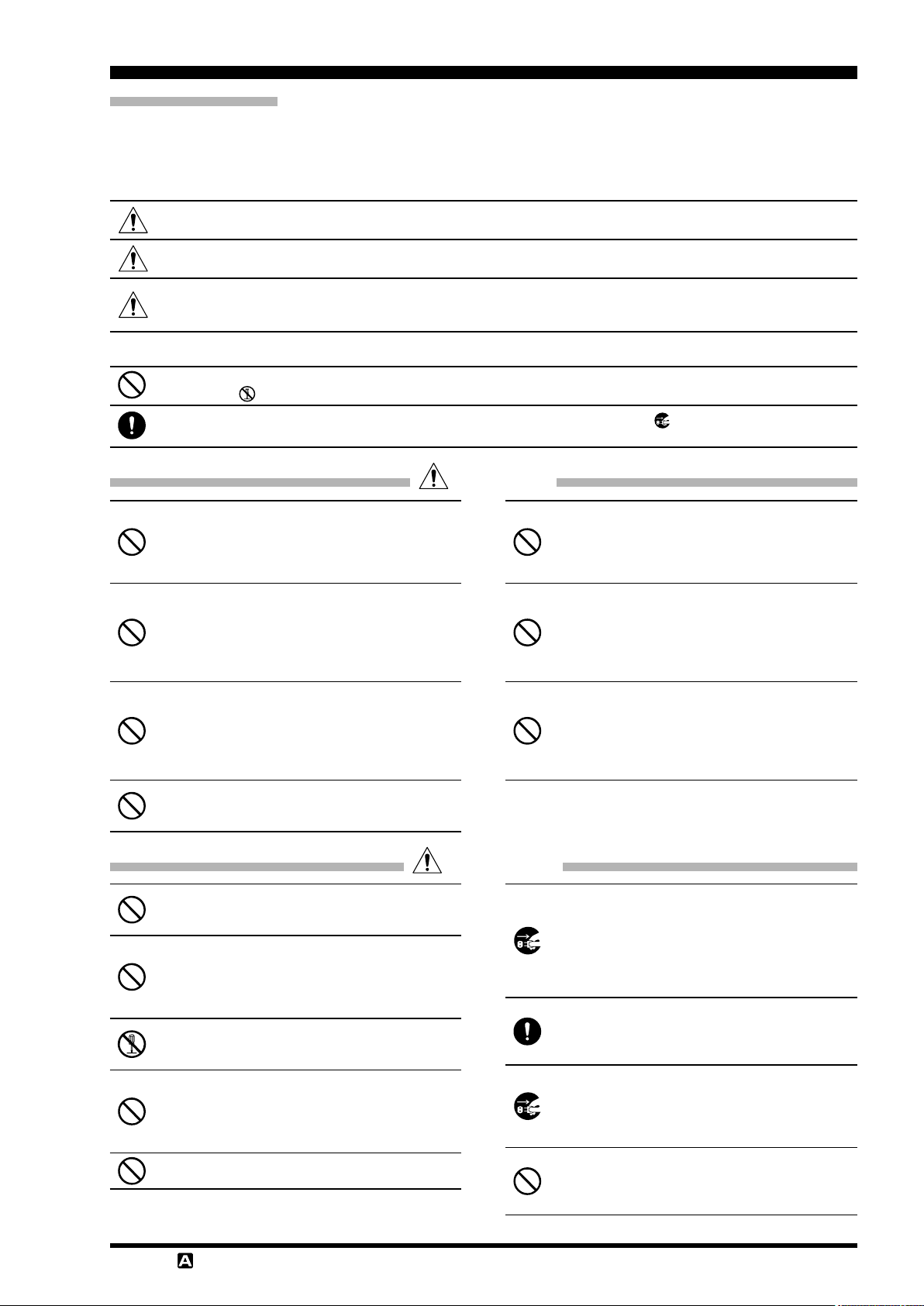
AvAilAble optionS
For details, see “Installation of Optional Accessories” on page 141 or the catalog.
Reference Microphone
M-1
Linear Amplier/AC Power Supply
VL-1000/VP-1000
Others
Hand Microphone
DTMF Hand Microphone
Dual Element Microphone
Ultra-High-Fidelity Desktop Microphone
Desktop Microphone
Active Tuning Antenna (Automatic Type)
Antenna Base Kit
Active Tuning Antenna (Manual Type)
Mobile Bracket
External Power Supply (13.8 VDC 23 A)
External Power Supply (13.8 VDC 25 A)
VL-1000
Packet Interface Cable
Linear Amplier Connection Cable
Lightweight Stereo Headphone
YH-77STA
A8J
MH-31
MH-36
M-100
MD-200
MD-100
ATAS-120A
ATBK-100
ATAS-25
MMB-90
FP-1023A
FP-1030A
CT-58
CT-39A
(equivalent to the supplied microphone
E8J
A8X
A8X
(U.S.A. only
Remote Control Keypad
FH-2
External Automatic Antenna Tuner
FC-40
)
)
Page 8 F
T-991
OperaTing Manual
beFOre yOu begin
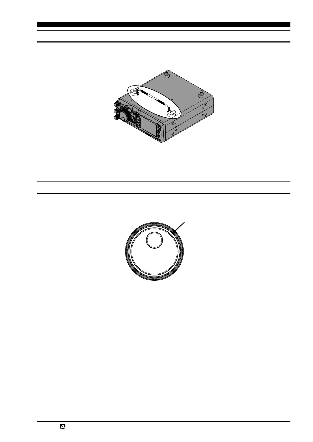
bASe StAtion Wire StAnd
The heavy wire stand on the bottom of the transceiver allows the transceiver to be tilted upward for better viewing. Simply fold the stand forward to raise the front of the transceiver, and fold it back against the bottom case to lower the front
of the
FT-991A
.
AdjuSting the MAin tuning diAl torque
The torque (drag) of the Main Tuning Dial knob may be adjusted according to your preferences. Rotate the skirt at the
base of the knob clockwise to reduce the drag, or counter-clockwise to increase the drag.
Skirt
T-991
OperaTing Manual
Page 9F
beFOre yOu begin
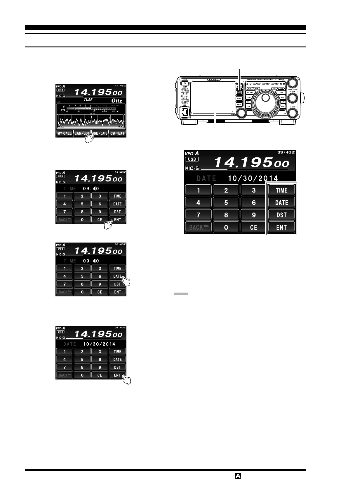
AdjuSting the clock
Use the following procedure to adjust the clock shown at the top right of the LCD display.
1. Press and hold the
2. Touch
3. Enter the present time with the number keys on the
[
TIME/DATE
LCD, then touch
MENU(SETUP
]
on the LCD.
[
]
.
ENT
)
button.
MENU(SETUP)
LCD
button
[
4. Touch
5. Enter month, day, and year with the number keys on
the LCD, then touch
6. Touch
mode display.
7. Press the
radio operation display.
]
DATE
[
on the LCD to switch the screen.
]
BACK
on the LCD to return to the setup
MENU(SETUP
[
]
.
ENT
)
button to return to the
[
Sets the time display. Touching this button toggles be-
tween UTC (Coordinated Universal Time) and the local
time. When UTC is displayed, “Z” appears on the right
side of the time.
note:
The user may decide the time preference.
The Local or UTC time must be set manually; the
time does not adjust automatically when the setting is
switched between Local and UTC time.
Only the “Z” indicator for UTC is changed.
[
Sets the date display. Touching this button toggles between MM/DD/YYYY and YYYY/MM/DD.
[
Touching this button switches daylight saving time be-
tween ON and OFF. When daylight saving time is set to
on, “D” appears on the right side of the time.
TIME
DATE
DST
]
]
]
Page 10 F
T-991
OperaTing Manual
beFOre yOu begin
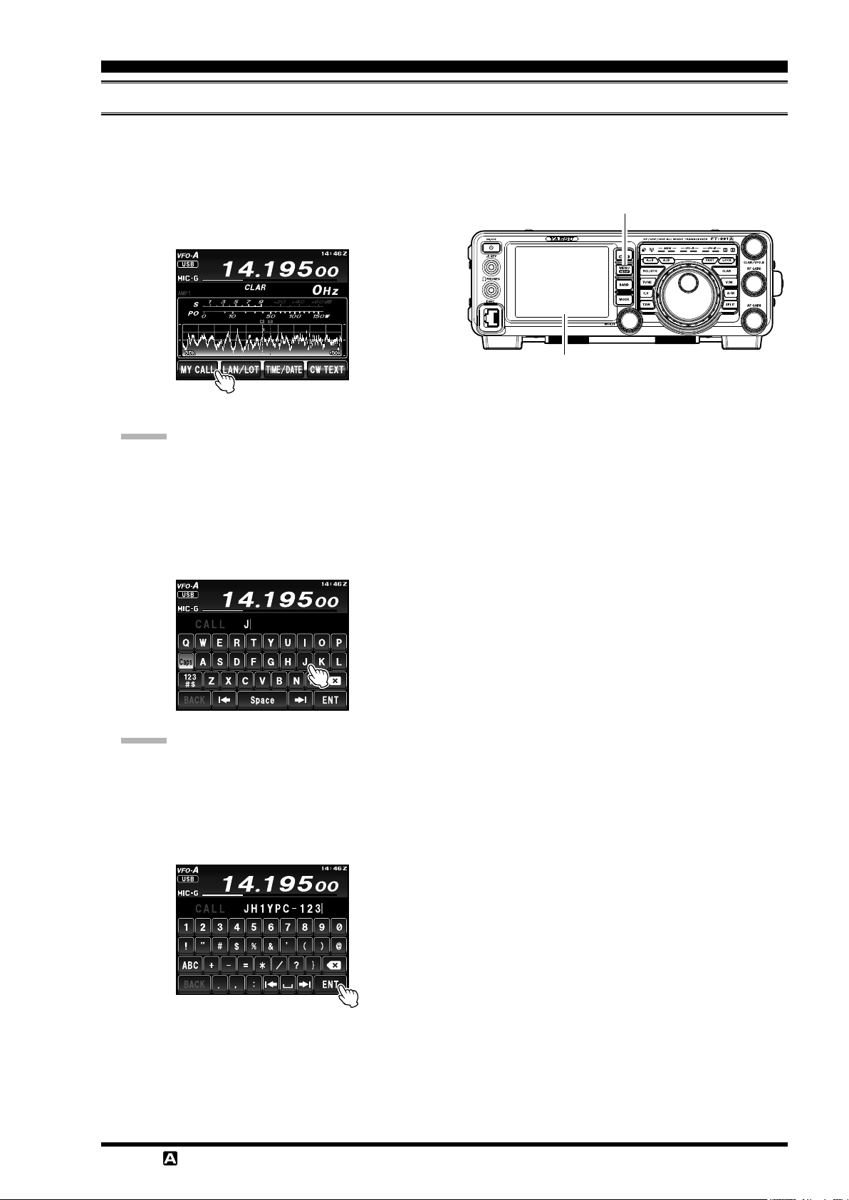
inputting the cAll Sign
When turning on the power for the rst time after purchase, or after resetting the transceiver, enter your own call sign.
The call sign will be displayed on the start screen when turning on the power and will be used to identify the station
when sending messages during digital communication.
1. Press and hold the
2. Touch
The time duration of the initial call sign start up
3. Touch a character key. The touched character will be
[
MY CALL
Advice:
screen display may be changed from the Menu item
“
005 MY CALL INDICATION
displayed at the top of the screen. Enter each character of your call sign.
MENU(SETUP
]
on the LCD.
)
button.
”.
MENU(SETUP)
LCD
button
Advice:
Up to 10 characters (letters, numbers, and sym-
bols) can be entered.
[
4. Touch
completed and the display will switch to the frequency display screen.
]
on the LCD. The call sign setting is
ENT
T-991
OperaTing Manual
Page 11F
beFOre yOu begin
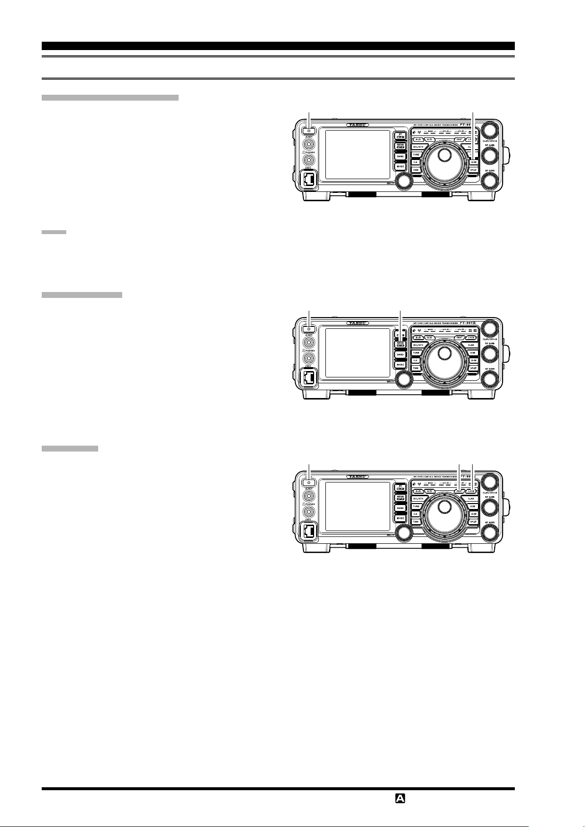
reSetting the MicroproceSSor
reSetting MeMorieS (only
Use this procedure to reset (clear) the previously stored
Memory channels, without affecting any conguration
changes you may have made to the Menu settings.
1. Press the front panel
transceiver off.
2. While holding the
in the front panel
ceiver on. Once the transceiver comes on, you may
release the buttons.
note:
The
(
and “
FT-991A
5-01
cannot erase the memory channels “01”
” through “
A
ON/OFF
5-10
)
ON/OFF
M
”: U.S. version).
switch to turn the
button in, press and hold
switch to turn the trans-
Menu reSetting
Use this procedure to restore the Menu settings to their
factory defaults, without affecting the programmed
memories.
1. Press the front panel
transceiver off.
2. While holding the
and hold in the front panel
the transceiver on. Once the transceiver comes on,
release the buttons.
ON/OFF
MENU(SETUP
switch to turn the
)
button in, press
ON/OFF
switch to turn
AM buttonON/OFF Switch
MENU(SETUP) ButtonON/OFF Switch
Full reSet
Use this procedure to restore all Menu and Memory settings to their original factory defaults. All Memories will
be cleared by this procedure.
1. Press the front panel
transceiver off.
2. While holding the
press and hold in the front panel
turn the transceiver on. Once the transceiver comes
on, release the buttons.
ON/OFF
FAST
switch to turn the
and
LOCK
ON/OFF
buttons in,
switch to
FAST Button LOCK ButtonON/OFF Switch
Page 12 F
T-991
OperaTing Manual
beFOre yOu begin
AntennA conSiderAtionS
The
FT-991A
erating frequency. While minor excursions from the 50-Ohm specication are of no consequence, if the Standing Wave
Ratio (SWR) present at the Antenna jack is greater than 3:1, the transceiver’s Automatic Antenna Tuner may not be able
to reduce the impedance mismatch to an acceptable value.
Every effort should be made to ensure that the impedance of the antenna system be as close as possible to the specied
50-Ohm value. Note that the “G5RV” type antenna does not provide a 50-Ohm impedance on all HF Amateur bands. An
external wide-range antenna coupler must be used with this antenna type.
Any antenna to be used with the
when using a “balanced” antenna such as a dipole, remember that a balun or other matching/balancing device must be
used to ensure proper antenna performance.
The same precautions apply to any additional (receive-only) antennas connected to the antenna jacks. If the receive only
antennas do not have impedance near 50 Ohms at the operating frequency, It may be necessary to install an external antenna tuner to obtain optimum performance.
is designed for use with any antenna system providing a 50 Ohm resistive impedance at the desired op-
FT-991A
must be fed from the transceiver with 50 Ohm coaxial cable. Therefore,
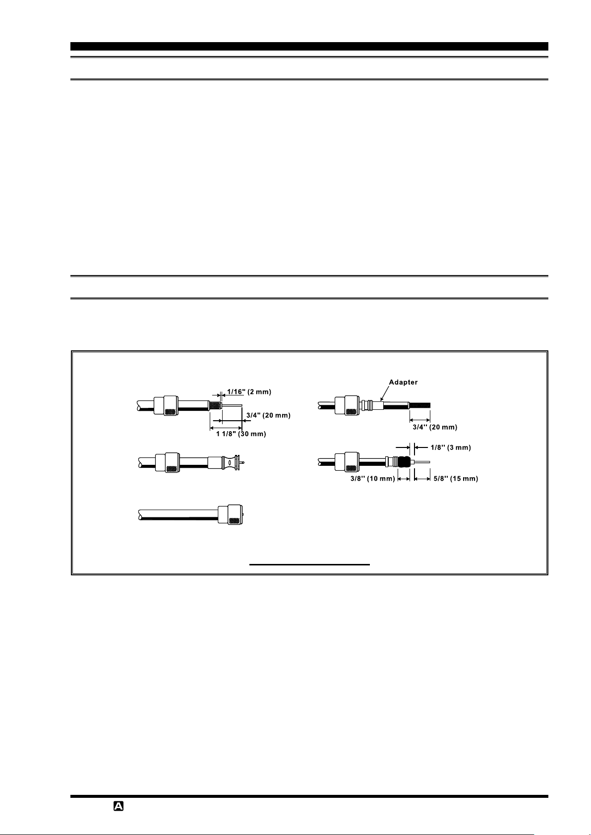
About coAxiAl cAble
Use high-quality 50-Ohm coaxial cable for the lead-in to your
antenna system will be wasted if poor quality, lossy coaxial cable is used. This transceiver utilizes standard “M” (“PL259”) type connectors.
FT-991A
transceiver. All efforts at providing an efcient
T-991
OperaTing Manual
typicAl pl-259 inStAllAtion
Page 13F
beFOre yOu begin
GND
Transceiver
GND
Linear
Amplifier
GND
TNC
"Daisy Chain"
GND
Linear
Amplifier
GND
TNC
GND
Transceiver
GND
Transceiver
GND
Linear
Amplifier
GND
TNC
"Daisy Chain"
grounding
The
FT-991A
transceiver, like any other HF communications apparatus, requires an effective ground system for maxi-
mum electrical safety and best communications effectiveness. A good ground system can contribute to station efciency
in a number of ways:
It can minimize the possibility of electrical shock to the operator.
It can minimize RF currents owing on the shield of the coaxial cable and the chassis of the transceiver. Such cur-
rents may lead to radiation, which can cause interference to home entertainment devices or laboratory test equipment.
It can minimize the possibility of erratic transceiver/accessory operation caused by RF feedback and/or improper
current ow through logic devices.
An effective earth ground system may take several forms. For a more complete discussion, see an appropriate RF engineering text. The information below is intended only as a guideline.
Typically, the ground connection consists of one or more copper-clad steel rods, driven into the ground. If multiple
ground rods are used, they should be positioned in a “V” conguration and bonded together at the base of the “V” which
is nearest the station location. Use a heavy, braided cable (such as the discarded shield from type RG-213 coaxial cable)
and strong cable clamps to secure the braided cable(s) to the ground rods. Be sure to weatherproof the connections
to ensure many years of reliable service. Use the same type of heavy, braided cable for the connections to the station
ground bus (described below).
Inside the station, a common ground bus consisting of a copper pipe of at least 25 mm diameter should be used. An alternative station ground bus may consist of a wide copper plate (single-sided circuit board material is ideal) secured to
the bottom of the operating desk. Grounding connections from individual transceivers, power supplies, and data communications devices (TNCs, etc.) should be made directly to the ground bus using a heavy, braided cable.
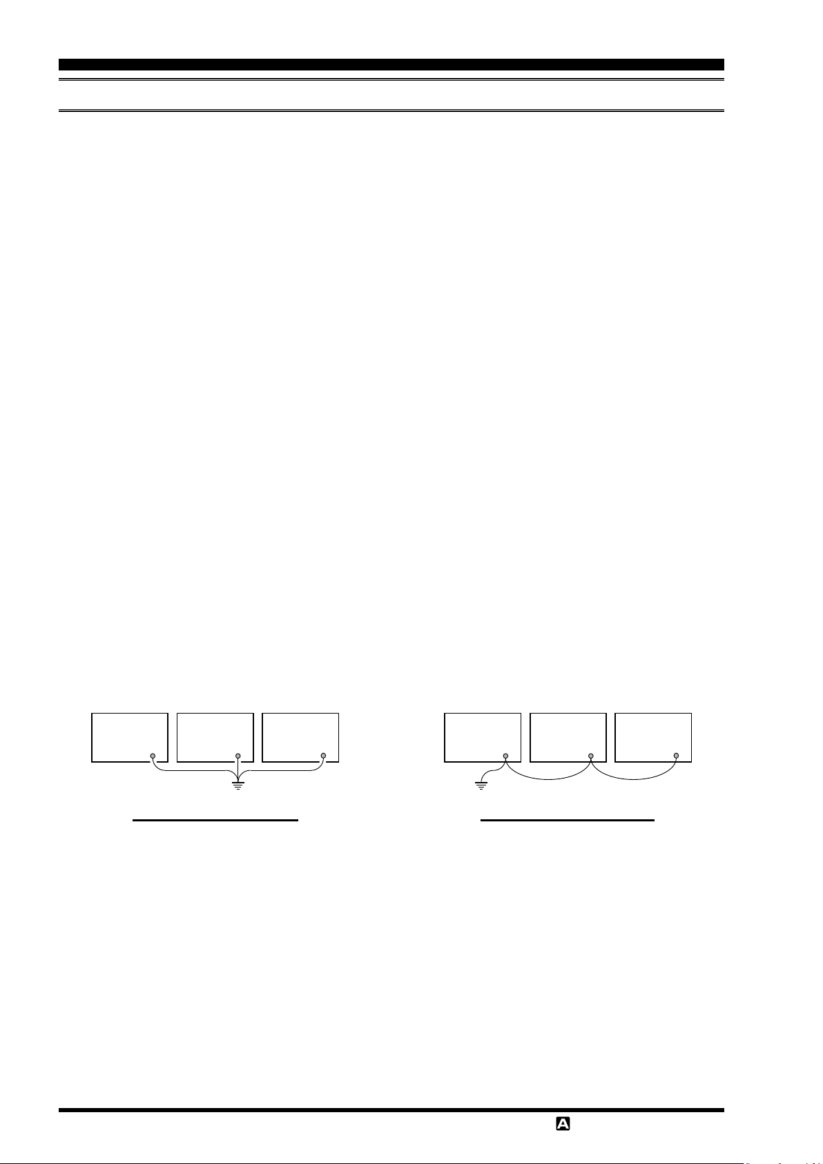
Do not “Daisy-Chain” ground connections from one electrical device to another and thence to the ground bus. This
method may nullify any attempt at effective radio frequency grounding. See the drawing below for examples of proper
grounding techniques.
Inspect the ground system - inside the station as well as outside - on a regular basis to ensure continued performance
and safety.
Besides following the above guidelines carefully, note that household or industrial gas lines must never be used in an
attempt to establish an electrical ground. Cold water pipes may, in some instances, help in the grounding effort, but gas
lines represent a signicant explosion hazard, and must never be used.
proper ground connection
iMproper ground connection
Page 14 F
T-991
OperaTing Manual
beFOre yOu begin
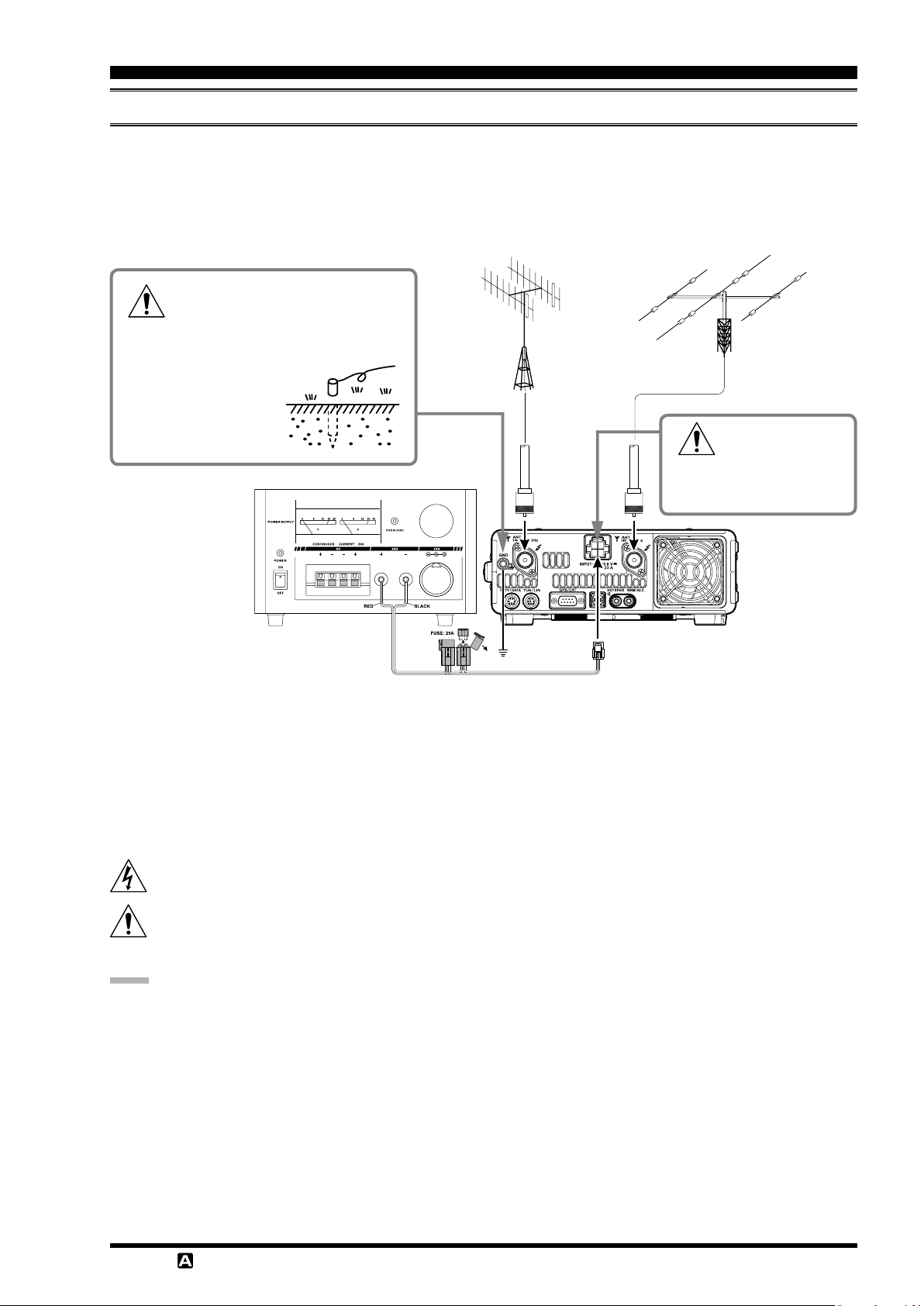
connection oF AntennA And poWer cAbleS
Please follow the outline in the illustration regarding the proper connection of antenna coaxial cables, as well as the DC
power cable. The DC power connector for the
(
±15 %), and capable of at least 23 Amperes of current. Always observe proper polarity when making DC connection:
The RED DC power lead connects to the Positive (+) DC terminal.
The BLACK DC power lead connects to the Negative (–) DC terminal.
To prevent damage from lightning, atmospheric electricity, electrical shock
etc., please provide a good earth ground.
Use a short, thick, braided cable to connect your
station equipment to the
buried ground rod (or
alternative earth ground
system).
FT-991A
must only be connected to a DC source providing 13.8 Volts DC
Check the DC volt-
age and current
rating (+13.8 V, 23 A) of the
power supply before connecting to the transceiver.
We recommend the use of the
be used with the
lines described above must be strictly followed.
Note that other manufacturers may use the same type of DC power connections as the
the wiring configuration may be different from that specified for the
caused if improper DC connections are made; consult with a qualied service technician when in doubt.
High RF voltage is present in the TX RF section of the transceiver while transmitting.
Absolutely! Do not touch the TX RF section while transmitting.
Permanent damage can result when improper supply voltage, or reverse-polarity voltage, is applied to the
991A
verse polarity DC, or DC voltage outside the specied range of 13.8 V ±15 %. When replacing fuses, be certain
to use a fuse of the proper rating. The
note:
Do not place the
Do not place the
Ensure adequate ventilation around the
due to high heat.
Do not install the
from above.
To minimize the possibility of interference to home entertainment devices, take all precautionary steps including
separation of TV/FM antennas from Amateur transmitting antennas to the greatest extent possible, and keep transmitting coaxial cables separated from cables connected to home entertainment devices.
Ensure that the DC power cord is not subject to undue stress or bending, which could damage the cable or cause it to
be accidentally unplugged from the rear panel
Be certain to install your transmitting antenna(s) so they cannot possibly come in contact with TV/FM radio or other
antennas, or with power or telephone lines.
FT-991A
. The Limited Warranty on this transceiver does not cover damage caused by application of AC voltage, re-
FT-991A
FT-991A
FT-991A
FP-1030A
, but the 13.8 VDC input voltage, 23 Ampere current capability, and DC cable polarity guide-
in a location with direct exposure to sunshine.
in a location exposed to dust and/or high humidity.
on an unstable desk or table. Do not place it in a location where objects may fall onto it
(USA market only) AC Power Supply. Other models of power supplies may
transceiver; however,
FT-991A
FT-991A
FT-991A
FT-991A
requires a 25 Amp blade fuse.
, to prevent heat build-up and possible reduction of performance
jack.
DC IN
transceiver. Serious damage can be
FT-
T-991
OperaTing Manual
Page 15F
insTallaTiOn anD inTercOnnecTiOns
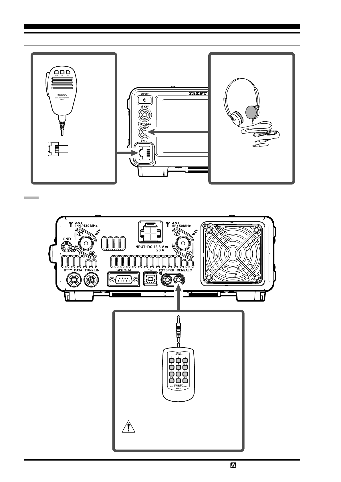
connection oF Microphone, heAdphone And reMote control keypAd
DOWN
UP
+5V
MIC GND
MIC
PTT
GND
FAST
Lightweight Stereo
Headphone
YH-77STA
note:
Make sure to turn off the power of the transceiver before connecting or disconnecting the microphone.
Remote Control Keypad
FH-2
If the
while the
991A
Turn off the power of the
or disconnecting the
plug is removed from the jack
FH-2
FT-991A
may be switched to the transmit mode.
FH-2
is in operation, the
FT-991A
.
before connecting
Page 16 F
T-991
FT-
OperaTing Manual
insTallaTiOn anD inTercOnnecTiOns
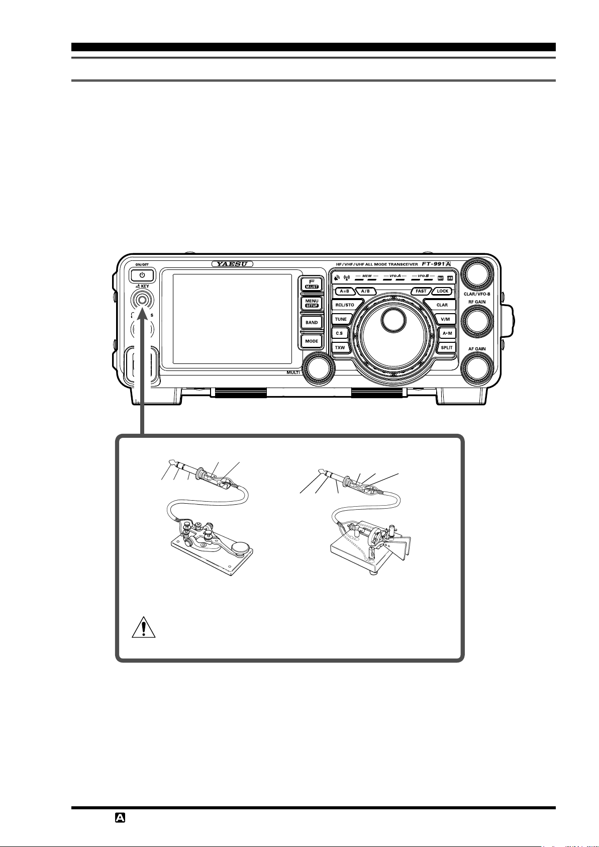
key, keyer, And coMputer-driven keying interconnectionS
The
FT-991A
later. Besides the built-in Electronic Keyer, two key jacks are provided, one on the front and one on the rear panel, for
convenient connection to keying devices.
The Menu selections permit conguring the front panel
keyer paddle may be connected to the front panel
input.
The
KEY
down current is approximately 4 mA. When connecting a key or other device to the
(
“stereo”) 3.5 mm phone plug; a 2-contact plug will place a short between the ring and shaft (ground) of the plug, result-
ing in a constant “key-down” condition in some circumstances.
includes many features for the CW operator. These functions will be detailed in the “Operation” section
jack according to the device connected. For example, a
KEY
jack on the
FT-991A
jack, and Menu item “
KEY
utilize “Positive” keying voltage. Key-up voltage is approximately +3.3V DC, and key-
012 KEYER TYPE
KEY
” used to select paddle
jack, use only a 3-contact
KEY
GND
KEY
NC GND
DOT DASH COMMON
Single key/Double-speed key Manipulator
If the Keyer plug is removed from the jack while the
the
FT-991A
Turn off the power of the
may be switched to the transmit mode.
FT-991A
before connecting or disconnecting the Keyer.
DOT DASH COMMON
FT-991A
is in operation,
T-991
OperaTing Manual
Page 17F
insTallaTiOn anD inTercOnnecTiOns
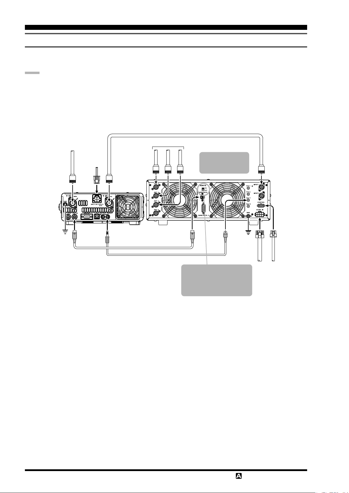
vl-1000 lineAr AMpliFier interconnectionS
Be sure that both the
FT-991A
and
VL-1000
are turned off, and then follow the installation recommendations contained
in the illustration.
note:
Refer to the
Do not attempt to connect or disconnect coaxial cables when your hands are wet.
Set the Menu item “
Since the ALC cable is connected to the
VL-1000
144/430MHz Antenna
ANT
Operating Manual for details regarding amplier operation.
143 TUNER SELECT
DC 13.8 V
144/430MHz
INPUT
REM/ALC
ANT
HF/50MHz
” to “
”.
LAMP
jack, the optional
Coaxial Cable (50Ω)
Connect to “INPUT 1” of the VL-1000
HF/50MHz Antenna
ANT 1
ANT 2
ANT 3
FH-2
Set the front panel’s
INPUT switch to the
“INPUT1”.
cannot be connected.
INPUT 1
GND
TUN/LIN
REM/ALC
CT-58 Band Data Cable (Option)
CT-58 ALC Cable (Option)
To link the FT-991A and VL-
1000 Power switches, set the
VL-1000 REMOTE switch to
the “ON” position.
ALC 1
BAND-DATA 1
GND
VP-1000
CONTROL
DC 48V IN
VP-1000
Page 18 F
T-991
OperaTing Manual

insTallaTiOn anD inTercOnnecTiOns
RESET (BAND D)
plug/connector pinout diAgrAMS
MIC GPS/CAT
(
as viewed from front panel
RTTY/DATA TUN/LIN
① ②
③ ④
⑤
⑥
(
as viewed from rear panel
DOWN
UP
+5V
MIC GND
MIC
PTT
GND
FAST
) (
① DATA IN
② GND
③ PTT
④ SHIFT
⑤ DATA OUT
⑥ SQL
) (
⑧⑨ ⑦ ⑥
① DCD
② SERIAL OUT/RXD
(GPS DATA IN)
③ SERIAL IN
④ DTR
⑤ GND
⑥ DSR
⑦ RTS
①②③④⑤
⑧ CTS
⑨ RI
as viewed from rear panel
as viewed from rear panel
+13V OUT
TX GND
GND
TX D (BAND A)
RX D (BAND B)
BAND C
TX INH
)
)
DC IN KEY
(
as viewed from rear panel
EXT SPKR PHONE
SIGNAL GND
TX REQ
Manipulator Single key/Double-speed key
DOT KEY GNDDASH COMMON
)
SIGNAL (RIGHT)
SIGNAL (LEFT)
Do not use
2-conductor type plug
GND
REM/ALC
NC
EXT ALC
T-991
OperaTing Manual
GND
REMOTE
GND
Page 19F
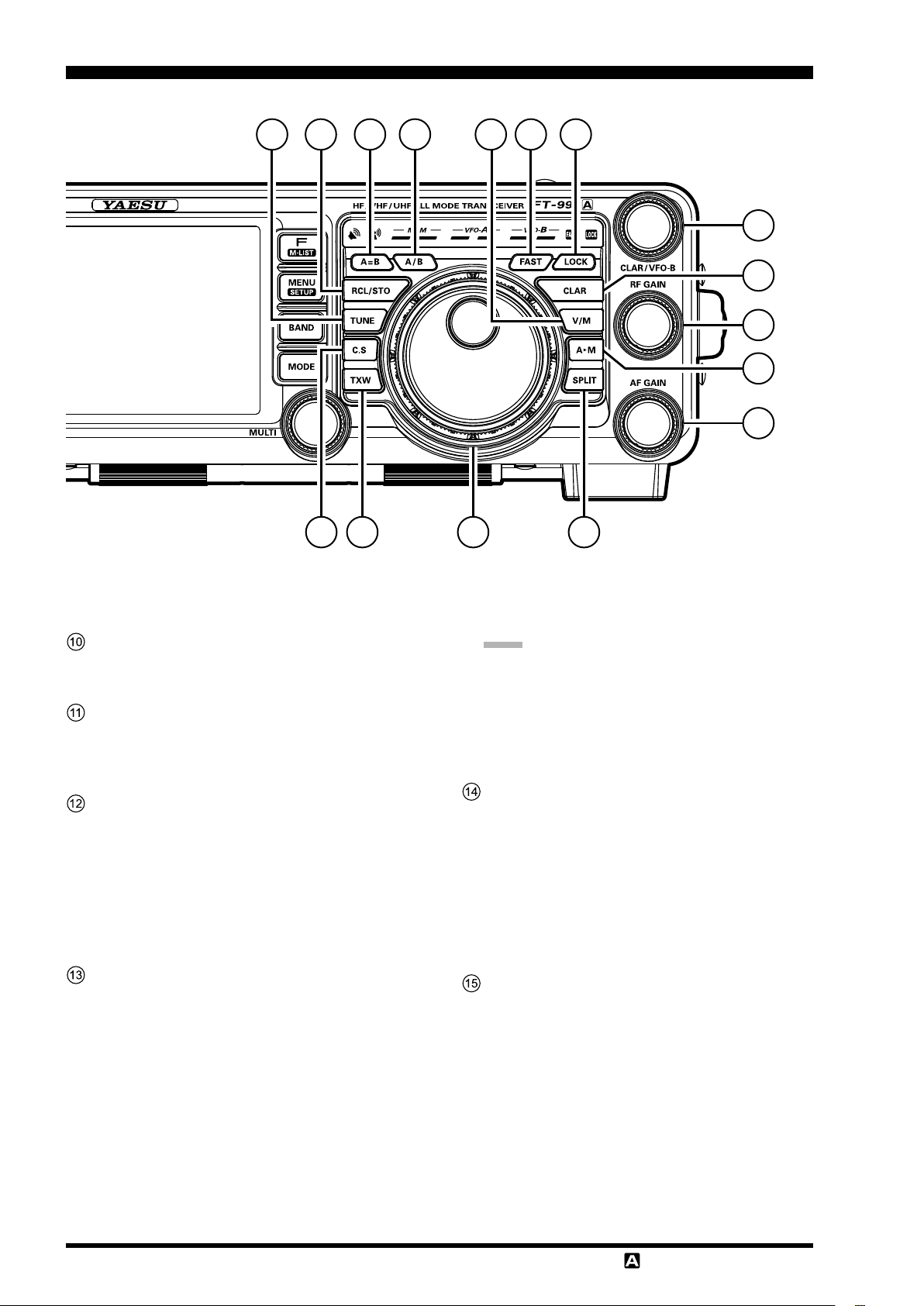
FrOnT panel cOnTrOls & swiTches
5
6
1
2
3
4
789
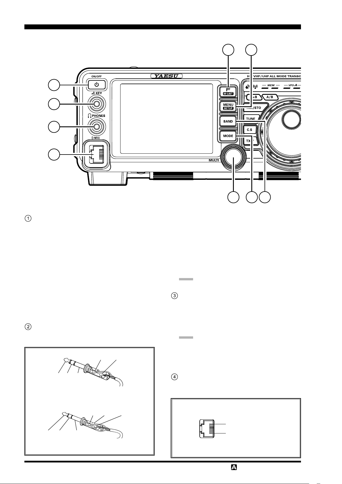
ON/OFF Switch
Press and hold in this switch for one second to turn
the transceiver on. Similarly, press and hold in this
switch for one second to turn the transceiver off.
Connect the
m
mercially available DC power supply. Turn the
DC supply on to place the transceiver in standby
mode. The transceiver must be in standby mode
to turn it on using the
tails on how to connect a commercially available
DC power supply, see page 15.
Press the
m
er is on, the receiver audio from the speaker will
be muted for about 3 seconds (Mute function).
FT-991A
ON/OFF
transceiver to a com-
ON/OFF
switch briey while the pow-
switch. For de-
KEY Jack
Connect a telegraph key or electronic keyer paddle
to use for CW mode operation.
KEY
GND
KEY
NC GND
When connecting a single straight key
When connecting a key or other device to the
m
jack, use only a 3-contact (“stereo”) 3.5
KEY
mm phone plug; a 2-contact plug will place a
short between the ring and the (grounded) shaft
of the plug, resulting in a constant “key-down”
condition.
Key-up voltage is +3.3 V, and key-down current
m
is about 4 mA.
note:
A 2-contact plug cannot be used in this jack.
PHONES Jack
Connect headphones to this ϕ3.5 standard stereo
jack.
Inserting a headphone plug into this jack will de-
m
activate the internal and external speakers.
note:
When wearing headphones, we recommend that you
turn the AF Gain levels down to their lowest settings
before turning power on, to minimize the impact on
your hearing caused by audio “
” during switch-on
pops
MIC Jack
This 8-pin jack accepts input from a microphone uti-
lizing a traditional YAESU HF transceiver pinout.
.
DOT DASH COMMON
DOT DASH COMMON
When connecting an electronic keyer paddle
Page 20 F
T-991
DOWN
UP
+5V
MIC GND
MIC
PTT
GND
FAST
OperaTing Manual
FrOnT panel cOnTrOls & swiTches
F(M-LIST
Press the button briey to display the function menu
screen where the operation settings for a variety of
functions may be congured.
Press this button again to close the function menu
screen.
Press and hold this button for more than one second
to display the menu list screen where the memory
channel data may be reviewed.
While displaying the memory data, rotate the
m
[
MULTI
channels.
Press this button again to close the memory list
screen.
MENU(SETUP
Press this button briey to display the menu mode
screen (see page 122) where you can set a variety
of functions.
Press this button again (or touch
touch panel) to close the menu mode screen.
Press and hold this button for more than 1 second to
display the setup screen where you can congure the
following settings.
•
MY CALL
•
LAT/LON
114
•
TIME/DATE
10
•
CW TEXT
Press this button again to close the setup screen.
)
Button
]
knob to review all data in memory
)
Button
[
BACK
: Setting the call sign (see page 11
: Setting longitude/latitude (see page
)
: Setting date and time (see page
)
: Entering CW TEXT (see page 89
]
on the
)
)
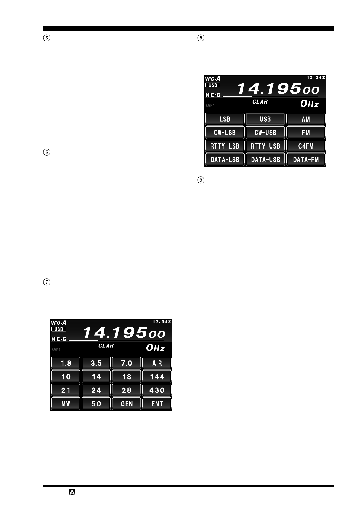
MODE Button
Switch the radio modulation form (operating mode).
Press this button to display the radio modulation
form selection screen, then touch and select your desired modulation form.
MULTI Knob
Adjust transmit output, microphone gain and opera-
tions of other functions (see page 24).
BAND Button
Switch the operation band (operation frequency
band). Press this button to display the operation band
selection screen, then touch and select the desired
band.
T-991
OperaTing Manual
Page 21F
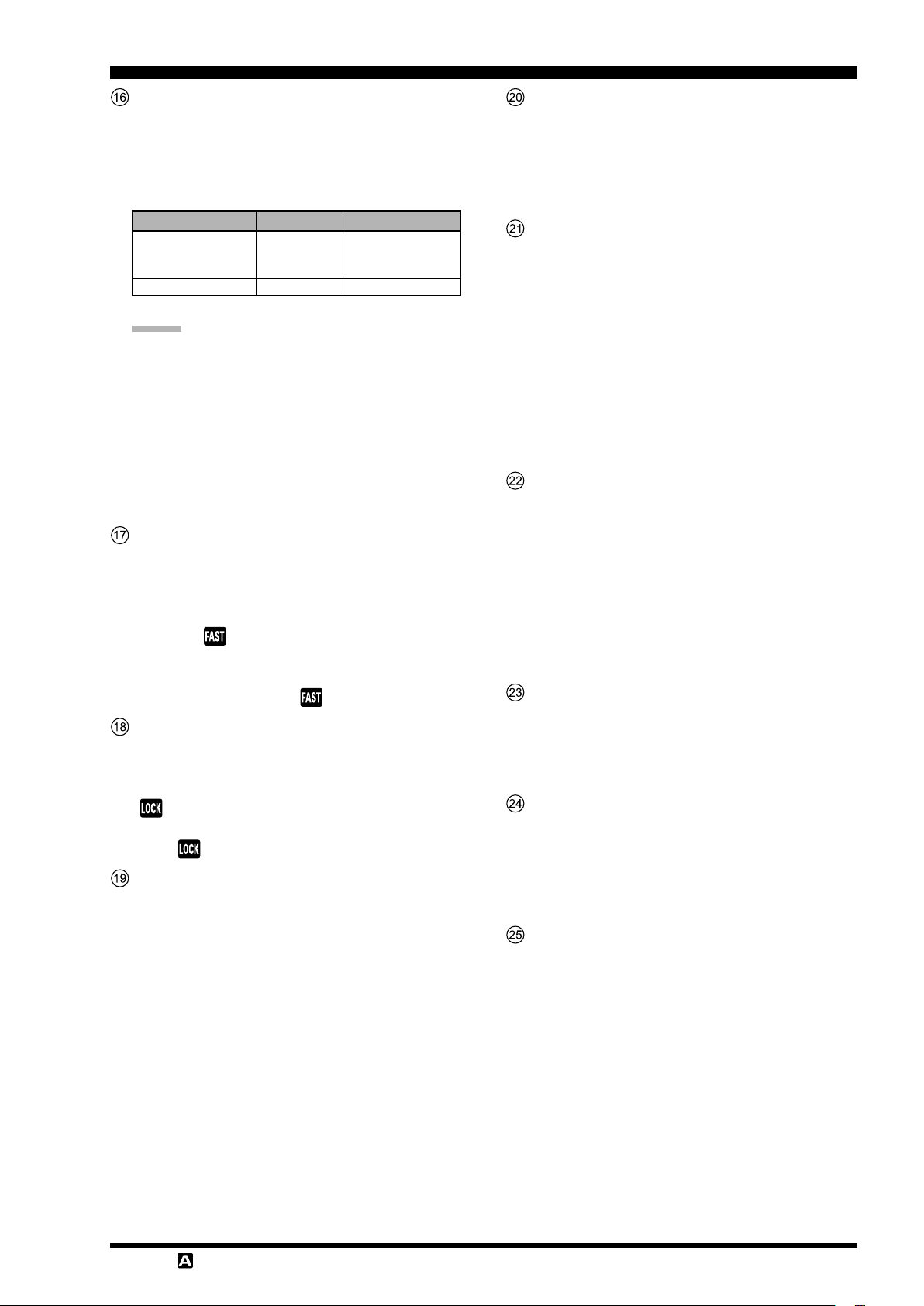
FrOnT panel cOnTrOls & swiTches
1213
201110 1817
23
19
24
21
25
1514
16
22
A=B Button
Pressing this button momentarily, sets the same fre-
quency and data values of VFO-A to VFO-B.
A/B Button
Pressing this button momentarily, exchanges the
frequency and memory channel data, of VFO-A and
VFO-B.
RCL/STO Button
Press and hold this button for more than one second
to write the frequency and data currently set for
VFO-A onto the quick memory bank (QMB) (see
page 99).
5 channels are available for QMB memories.
m
Press the button briey to recall the data written onto
the quick memory banks (QMB) one by one.
TUNE Button
This is the on/off switch for the
Antenna Tuner.
Press the
m
“
TUNER
vate the antenna tuner.
Press the
“
TUNER
tuner.
Press the
m
start “automatic tuning”. The “
tor will ash.
[
” indicator on the touch panel and acti-
[
TUNE
” indicator off and disable the antenna
[
]
TUNE
TUNE
button briefly to display the
]
button briey again to turn the
]
button for about 1 second to
FT-991A
Automatic
TUNER
” indica-
note:
Since the transceiver transmits automatically dur-
ing automatic tuning, make sure to connect an
antenna or dummy load before tuning up.
When the antenna or dummy load does not match
the impedance, “
touch panel.
HI-SWR
” will appear on the
C.S Button
Press this button momentarily to directly recall a fa-
vorite Menu Selection.
To program a Menu selection to the
m
press the
Menu. Select the Menu item you want to set as
the short cut. Press the
MENU(SETUP
lected Menu item as the short cut.
MENU(SETUP
)
button; this will lock in the se-
)
button to enter the
button, then press the
C.S
C.S
button,
TXW Button
During a split operation, press and hold the
button to listen on the transmitter frequency while
holding the button.
TWX
Page 22 F
T-991
OperaTing Manual
FrOnT panel cOnTrOls & swiTches
Main Tuning Dial Knob
This large knob adjusts the operating frequency of
VFO-A.
Rotate clockwise to increase the operating frequency
and rotate counter-clockwise to decrease the operating frequency.
operAting Mode 1 Step 1 diAl rotAtion
LSB/USB/CW/RTTY/
DATA-LSB/DATA-
USB/AM
FM/DATA-FM/C4FM
Numbers in parentheses indicate steps when the FAST button is On.
Advice:
The tuning steps for the Main Dial knob are set
at the factory to: 10Hz (SSB/AM), 5 Hz (CW/
RTTY/DATA-LSB/DATA-USB) and 100 Hz (FM/
DATA-FM/C4FM) per step.
In LSB, USB, CW, RTTY, DATA-LSB or DATA-
USB mode, the frequency change amount (step
width) may be toggled between “
by pressing the
ing [
5/10Hz
] on the LCD.
5 Hz (100 Hz
10 Hz (100 Hz
100 Hz (1 kHz)20 kHz (200 kHz
F(M-LIST
)
1 kHz (20 kHz
)
2 kHz (20 kHz
” and “
5Hz
)
button, and then touch-
10Hz
)
)
)
”
FAST Button
Pressing this button will change the tuning of the
Main Tuning Dial knob (VFO-A) to a higher step
rate.
Press this button to double the main dial frequency
variation. “
up.
Press this button again to restore the frequency varia-
tion to the original value. “
” in the LED indicator area will light
” will disappear.
LOCK Button
This button toggles on/off locking of the Main Tun-
ing Dial knob.
Press this button to lock the main dial operations.
“ ” will light up in the LED indicator area.
Press this button again to unlock the main dial opera-
tions. “ ” will disappear.
CLAR Button
During reception, press this button, then rotate the
CLAR/VFO-B
RX clarier offset value (see page 36).
The clarier offset value (frequency) can be re-
m
stored to “0 (zero)” by pressing the
for more than 1 second.
Depending on the menu mode “
m
MODE SELECT
the TX clarifier for changing only the transmit
frequency (see page 75) or RX/TX clarifier for
both receiving and transmitting (see page 36,
75).
knob to adjust the VFO-A
CLAR
040 CLAR
” setting, this button can work as
button
V/M Button
This button toggles frequency control between VFO-
A and the memory system.
Pressing this button alternately recalls the VFO
m
frequency data and the frequency data saved in a
memory channel by turns.
AM Button
Pressing and holding this key for one second (until
the double beep) copies the current operating data
into the currently selected memory channel, overwriting any previous data stored there.
Press this button briey to display the memory check
function screen, where the data saved in a memory
channel may be reviewed.
While displaying memory data, rotate the
m
knob to review the data in each memory channel.
Press this button again, to close the memory list
screen.
MULTI
SPLIT Button
Press this button to operate split frequency between
VFO-A (used for reception) and VFO-B (used for
transmission) (see page 76).
Press and hold in the
m
ond to engage the “Quick Split” (see page 76)
feature. VFO-B transmit will automatically be
set to a frequency 5 kHz higher than the VFO-A
receive frequency, with the same operating mode.
The transceiver will operate in the Split mode.
button for one sec-
SPLIT
CLAR/VFO-B Knob
During the VFO-A operation, rotate this knob to ad-
just the clarier.
During Split operation, this knob adjusts the operat-
ing frequency of VFO-B.
RF GAIN Knob
Adjust the receiver gain of the high frequency and
mid-range frequency amplier stages.
Rotate the knob clockwise to increase the gain.
m
Rotate the knob fully clockwise to set the gain to
the highest level for normal operations.
AF GAIN Knob
The
AF GAIN
level.
Rotate the knob clockwise to increase the receiv-
m
er audio volume level.
knob sets the receiver audio volume
T-991
OperaTing Manual
Page 23F
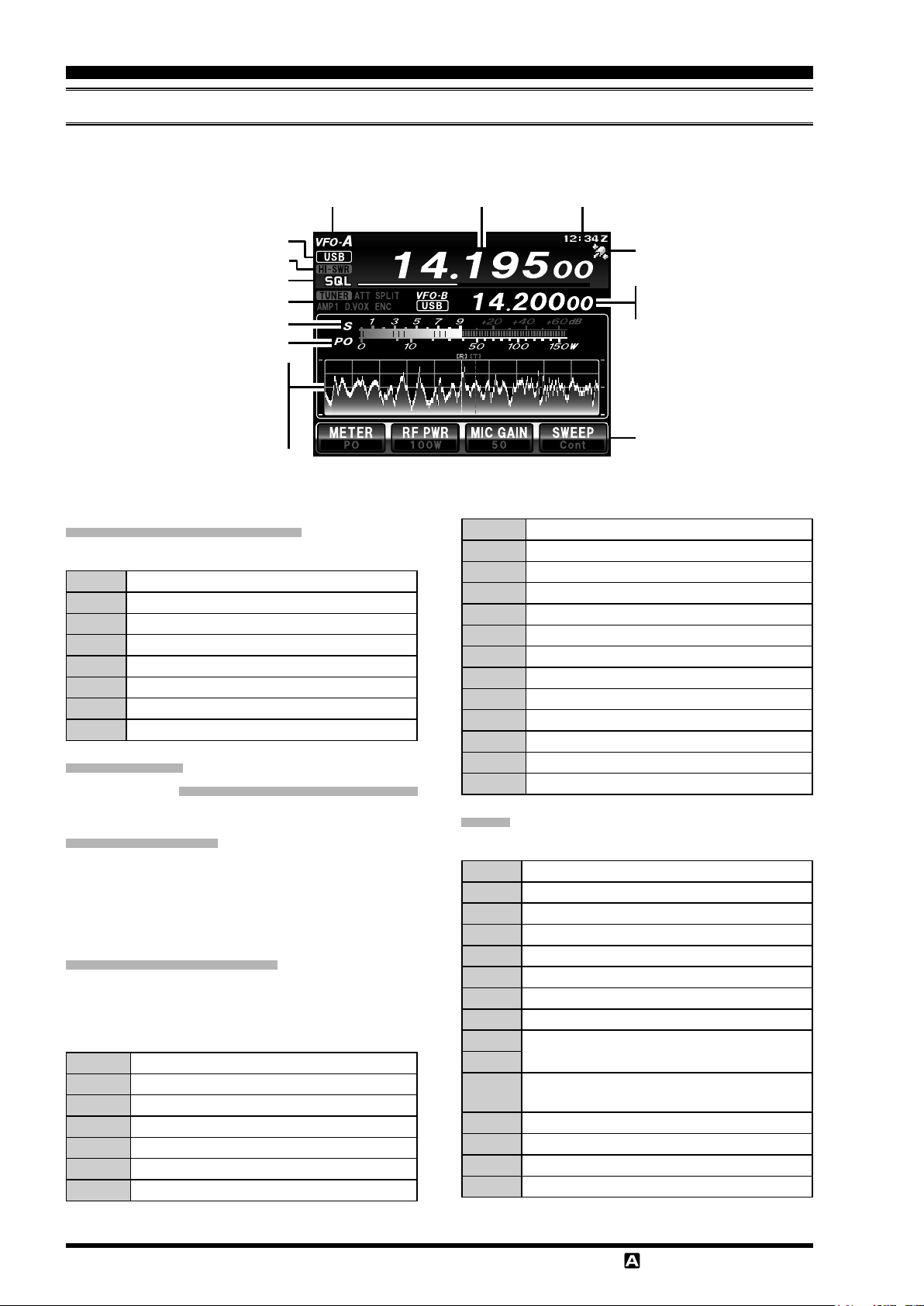
abOuT The Display
tFt liquid cryStAl diSplAy
A variety of information such as VFO-A/VFO-B frequencies, mode, S-meter will appear on the LCD.
Operating mode
Mode (radio modulation form)
HI-SWR
MULTI knob operation
Icons
S-meter
Meters
Scope
Waterfall
Menu list
Memory list
Function menu
Operating Mode Indicators
Displays the current operating mode.
VFO-A Operating in VFO-A mode
MEM Operating in memory mode
MT The memory tuning feature is in use
QMB Operating with the quick memory feature
PMS Programmable memory scanning
MCK The memory check function is in use
HOME Recalling the home channel
EMG Recalling the frequency for emergency contact
Current Mode
(
Modulation Form) Indicator
Displays the current modulation form.
HI-SWR Indicator
Indicates antenna matching errors.
When this warning appears, stop transmitting immediately, check and repair the antenna, connectors, cables,
etc.
MULTI Knob Operations
Displays the functions operated with the
(
see page 21).
The progress bar shows the operation status.
RF-P Adjusts transmission output
MIC-G Adjusts the microphone gain
NB-L Adjusts the noise blanker level
SHIFT Shift function
WIDTH Width function
NOTCH Notch function
CONT Contour function
MULTI
knob
ClockOperation frequency
GPS signal capturing
VFO-B data
Clarifier operation
Main control buttons
DNR Digital Noise Reduction function
PROC Adjusts Speech Processor Gain
MONI Adjusts the monitor level
DT-G Adjusts the input level during data communication
CH-D Frequency tuning in the pre-programmed steps
SPEED Adjusts keying speed
APF Audio Peak Filter function
PITCH Adjusts the CW pitch
SQL Adjusts the squelch level
TONE Selects the tone frequency
DCS Selects the DCS code
MCH Selects the memory channel
GRP Selects the memory group
Icons
Displays currently used functions.
TUNER Antenna tuner
ATAS Active Tuning Antenna System
ATT The attenuator is in use
SPLIT Running split operation
DUP Recalling duplex memories
[+] Plus shift
[-] Minus shift
IPO The receiver amplier is OFF
AMP1
AMP2
D.VOX
VOX The VOX function is in use
ENC The tone encoder is in use
DEC The tone decoder is in use
DCS The digital code squelch is in use
The receiver amplier is ON
The VOX function activates during data communication
Page 24 F
T-991
OperaTing Manual
abOuT The Display
tFt liquid cryStAl diSplAy
PLAY
REC
The voice memory/contest memory keyer functions are in use.
PLAY: Playing, REC: Recording
S-Meter
Displays the reception signal strength.
To change the meter peak hold time
1. Press the
2. Rotate the
MTR PEAK HOLD
3. Touch
MULTI
(
OFF/0.5/1.0/2.0 seconds).
4. Touch
MENU(SETUP
MENU(SETUP
MULTI
[
SELECT
knob to select the time to hold
[
ENTER
knob to select “
”.
]
, then rotate the
]
, then
)
button.
)
button.
[
BACK
009 BAR
]
or press the
Meters
The following information can be displayed below the
S-meter.
The displayed information is switched each time [
] is touched on the panel.
TER
PO Displays transmitter output power.
ALC Displays ALC voltage
SWR Displays antenna matching state
COMP Displays the speech processor compression level
ID
VDD
Displays the drain current of the nal stage FET
transistors
Displays the drain voltage of the nal stage ampli-
er.
The proper voltage is 13.8 V.
ME-
Clock
Indicates the current time.
When receiving a GPS signal, the time is set automati-
cally.
GPS Signal Capturing Indicator
Appears when an external GPS device is connected to
the
GPS/CAT
are being acquired.
jack on the rear panel and GPS signals
VFO-B Data/Clarier Operation
Displays operation status of the radio modulation form
and VFO-B frequency, etc.
Displays the offset operation status and the clarier off-
set value, etc.
”.
” to “
)
SWAP
Main Control Buttons (SWAP
Frequently used functions can be assigned to these buttons.
To change the function assigned
to the main control button
1. Press the
2. Touch
“
SWAP F1
3. Touch one of the “
F4
want to change ashes.
4. Touch
tion you want to assign, then select and
touch the function.
5. Press the
F(M-LIST
[
BACK
” to “
” screens and conrm the function you
[
BACK
F(M-LIST
)
]/[
FWD
SWAP F4
SWAP F1
]/[
FWD
)
button.
]
to display screens
]
to display the func-
button.
Scope/Waterfall
Displays a spectrum or waterfall when the scope function (see page 42) is in use.
Menu List
Displays the menu item list when making settings in the
menu mode.
Memory List
Displays the data saved in the memory channels.
Function Menu
Displays the function menu from which you can set a
variety of functions.
Touch
[
BACK
]/[
]
to switch the menu screen.
FWD
Operation Frequency
Displays the current operation frequency.
T-991
OperaTing Manual
Page 25F
abOuT The Display
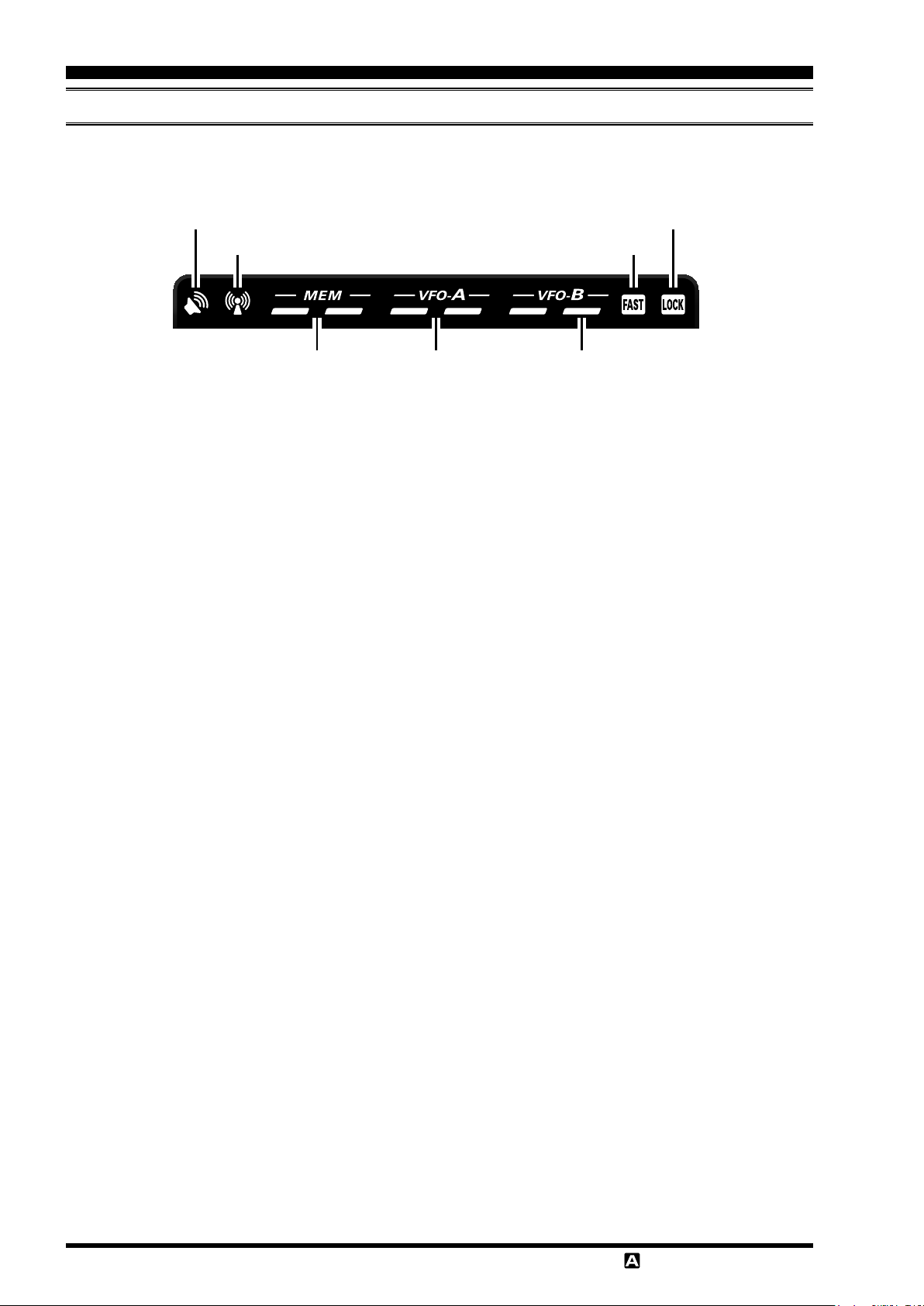
led indicAtorS
Displays the transmit/receive status of the transceiver, and the main dial “
RX Indicator
TX Indicator
Memory Mode
RX/TX
Indicators
RX Indicator (Green
This indicator illuminates when the squelch opens.
TX Indicator (Red
This indicator illuminates during transmission.
)
)
Main Band
RX/TX
Indicators
Sub Band TX Indicator
Red (Right):
This indicator illuminates when the transmitter is active
on the main band (VFO-B).
FAST Indicators
Memory Mode RX/TX Indicators
Green (Left):
This indicator illuminates when the receiver is active on
the memory channel.
Red (Right):
This indicator illuminates when the transmitter is active
on the memory channel.
This indicator appears when the Main Tuning Dial knob
tuning rate is set to “fast” (see page 23).
LOCK Indicators
This indicator appears when the Main Tuning Dial knob
is locked (see page 23).
” and “
FAST
LOCK Indicators
FAST Indicators
Sub Band
TX
Indicator
LOCK
”.
Main Band RX/TX Indicators
Green (Left):
This indicator illuminates when the receiver is active on
the main band (VFO-A).
Red (Right):
This indicator illuminates when the transmitter is active
on the main band (VFO-A).
Page 26 F
T-991
OperaTing Manual
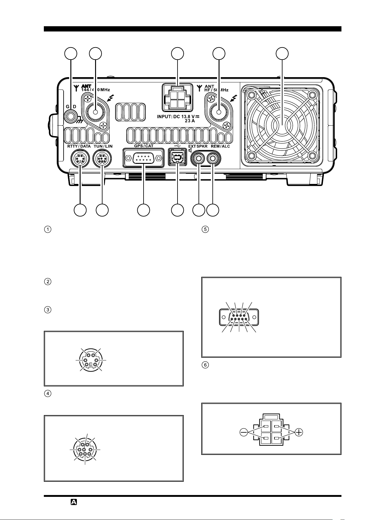
rear panel
1
2
43
5
7 869
GND
Use this terminal to connect the transceiver to a good
earth ground, for safety and optimum performance.
Use a large diameter, short braided cable to make
the ground connections. For details on grounding the
transceiver, see “Grounding” on page 14.
10
11
GPS/CAT Jack
This is the
or a commercially available external GPS device.
Connecting a computer to this jack, using a com-
mercially available
CAT control of the transceiver.
RS-232C
jack for connecting a computer
RS-232C
straight cable, enables
ANT Jack (144/430MHz
This is the M-type coaxial connector for the 144
MHz band and 430 MHz band antennas (50 ohms).
)
RTTY/DATA Jack
This is the input/output jack to connect a terminal
unit for RTTY and TNC for packet communications.
① ②
③ ④
⑤
⑥
① DATA IN
② GND
③ PTT
④ SHIFT
⑤ DATA OUT
⑥ SQL
TUN/LIN Jack
Connect the optional external antenna tuner “
or the linear amplier “
VL-1000
+13V OUT
TX GND
GND
TX D (BAND A)
RX D (BAND B)
BAND C
RESET (BAND D)
TX INH
”.
FC-40
”
① DCD
⑧⑨ ⑦ ⑥
② SERIAL OUT/RXD
(GPS DATA IN)
③ SERIAL IN
④ DTR
⑤ GND
⑥ DSR
⑦ RTS
①②③④⑤
⑧ CTS
⑨ RI
DC IN Jack
This is the DC power supply connection for the
transceiver. Use the supplied DC cable to connect directly to a DC power supply, which must be capable
of supplying at least 23 A @13.8 VDC.
T-991
OperaTing Manual
Page 27F
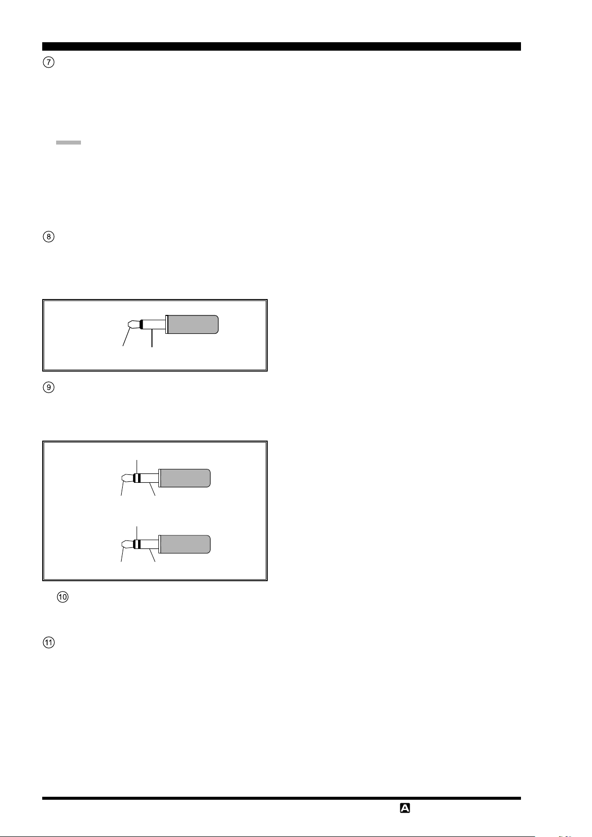
rear panel
USB Jack
Connect a computer with a commercially available
USB cable to control the transceiver remotely from
the computer using the CAT command.
Inputting/Outputting audio signals and transmission
control can also be done from the computer.
note:
To control the transceiver remotely from the
computer, a USB driver is required. For details
on the USB driver, visit the Yaesu website.
When using a USB cable connected to a com-
puter, the transceiver may change to the transmit
mode when the computer is started.
EXT SPKR Jack
This is the monaural jack to connect an external
speaker (4 Ω to 8 Ω).
Connecting an external speaker to this jack will de-
activate the internal speaker.
SIGNAL GND
REM/ALC Jack
Connect the optional remote control keypad “
When a device such as a linear amplier is connect-
ed, this is an external ALC current input jack.
TX REQ
EXT ALC
REMOTENCGND
ANT Jack (HF/50MHz
This is the M-type coaxial connector to connect HF
band and 50 MHz band antennas (50 ohms).
GND
)
FH-2
”.
Cooling fan
Page 28 F
T-991
OperaTing Manual
Loading...