


FTM-100DR/DE
Operating Manual
144/430 MHz
DUAL BAND TRANSCEIVER
C4FM/FM
Before Use 
Installation and Connection 
Basic Operations 
DG-ID and DP-ID Function 
Using the Memory 
Scanning 
Using the GPS Function 
Using the APRS Function 
Using the GM Function 
Using the WIRES-X Function 
Convenient Functions 
Customizing Menu Settings and
User Preferences
Appendix 

Introduction
Features of this transceiver
|
144/430 MHz dual-band transceiver equipped with standard C4FM digital |
|
|
communication modulation |
|
|
Clear audio and data communication are achieved using the digital modulation |
|
|
functions |
|
|
With the DG-ID (Digital Group ID), the Group Monitor (GM) feature enables automati- |
|
|
cally locating, and communicating with other stations that have the same DG-ID num- |
|
|
ber within contact range, by utilizing a matching group ID number from 00 to 99 |
|
|
The Digital Personal ID (DP-ID) feature may communicate only by the transceivers |
|
|
registered the individual ID information that is different for each transceiver included in |
|
|
the transmission radio wave of C4FM digital communication |
|
|
Wide-band receives in the 108 MHz to 999 MHz range (air band, information wireless band) |
|
|
Transmit power 50 watts with cooling fan |
|
|
The dot matrix LCD is mounted on the front panel |
|
|
500 memory channels in the A-band and 500 channels in the B-band |
|
| <![if ! IE]> <![endif]>Before |
Your frequency memory channels and transceiver configuration settings can be backed |
|
up using a micro-SD memory card. The data on the micro-SD memory card can easily |
||
|
||
| <![if ! IE]> <![endif]>Use |
be copied to other transceivers |
|
A choice of scanning functions (including VFO scan, memory scan) |
||
|
Built-in GPS receiver unit displays your station location and movement information. |
|
|
Connection to external GPS devices is enabled. |
|
|
*Refer to the separate “Advance Manual” |
|
|
Incorporated APRS® function enables data communication of location information and |
|
|
messages |
|
|
*Refer to the separate “APRS Instruction Manual” |
|
|
GM (Group Monitor) function in which frequently communicating members can be |
|
|
registered as a group, thereby allowing location information and messages to be |
|
|
exchanged |
|
|
*Refer to the separate “GM Instruction Manual” |
|
|
Supports Yaesu WIRES-X Internet linking, enabling communication with remote |
|
|
partners via the Internet |
|
|
*Refer to the separate “WIRES-X Instruction Manual” |
|
|
Bluetooth adaptor unit BU-2 (sold separately) permits hands-free operation |
|
|
*Refer to the separate “Advance Manual” |
|
|
Voice guide unit FVS-2 (sold separately) provides voice announcements and |
|
|
recording of received audio |
|
|
*Refer to the separate “Advance Manual” |
|
|
* The Advance Manual, WIRES-X, APRS, and GM Instruction Manuals are not |
|
|
included with this product. Please download them directly from the Yaesu website. |
2
Introduction
About registered trademarks and copyrights
APRS is a registered trademark of Mr. Bob Bruninga WB4APR. SmartBeaconing is supplied by HamHUD Nichetronix.
Microsoft, Windows and Windows Vista are registered trademarks of Microsoft Corporation in the United States and other countries.
Bluetooth® is a registered trademark of the Bluetooth SIG.
Other company and product names listed in this manual are trademarks and registered trademarks of their respective companies.
Unauthorized reproduction or copying of a part or all of the copyrights owned by Yaesu Musen Co., Ltd. in any form whatsoever is strictly prohibited.
How to read this manual
In this manual, front panel operations are described as follows.
Press |
..................................... Indicates that the key or switch is to be pressed |
|
briefly. |
Press .... |
for over one second Indicates that the key or switch is to be pressed for |
|
over one second. |
The following symbols are also used in this manual:
Caution
...Explains caution to observe during operation.
Tip
...Explains operating suggestions or useful tips.
Also note: the actual product may differ from the drawings shown in this manual.
<![endif]>Use Before
3

<![endif]>Use Before
Contents |
|
Introduction................................................................. |
2 |
Features of this transceiver.................................... |
2 |
About registered trademarks and copyrights ......... |
3 |
How to read this manual ........................................ |
3 |
Before Use................................................................. |
5 |
Safety Precautions (make sure to read these) ........... |
5 |
Checking the supplied items....................................... |
9 |
Name and function of each component.................... |
10 |
Front panel........................................................... |
10 |
Front................................................................ |
10 |
Rear ................................................................ |
12 |
Main body ............................................................ |
12 |
Front................................................................ |
12 |
Rear ................................................................ |
13 |
Microphone (MH-48A6JA) ................................... |
14 |
Screen display ..................................................... |
15 |
Input characters ................................................... |
16 |
Switching the character type ........................... |
16 |
Deleting the input characters .......................... |
16 |
Moving the cursor to the left............................ |
16 |
Moving the cursor to the right.......................... |
16 |
Deleting the most recently input character...... |
16 |
Completing input ............................................. |
16 |
Installation and Connection .................................. |
17 |
Installing the transceiver........................................... |
17 |
Precautions on installation................................... |
17 |
Installation location when used in a mobile unit... |
18 |
About the antenna................................................ |
19 |
Installing the antenna ...................................... |
19 |
Installing the main body ....................................... |
20 |
Installing the front panel....................................... |
21 |
Connecting the transceiver....................................... |
22 |
Connecting the front panel to the main body ....... |
22 |
Connecting the microphone................................. |
22 |
Connecting the antenna....................................... |
22 |
Connecting the power supply ................................... |
23 |
Connecting the car battery .............................. |
23 |
Connecting the external power supply |
|
equipment ....................................................... |
23 |
Basic Operations.................................................... |
24 |
Receiving.................................................................. |
24 |
Turning the power on ........................................... |
24 |
Switching the power off........................................ |
24 |
Inputting the call sign ........................................... |
24 |
Toggling the operating band ................................ |
25 |
Adjusting the volume level ................................... |
25 |
Adjusting the squelch level .................................. |
26 |
Tuning in to the frequency ................................... |
27 |
Changing the frequency steps ............................. |
27 |
Switching the operation mode.............................. |
28 |
Selecting communication mode........................... |
29 |
Switching the modulation mode........................... |
30 |
Communicating......................................................... |
31 |
Transmitting ......................................................... |
31 |
Adjusting the transmit power........................... |
32 |
Communicating in FM mode................................ |
32 |
Communicating using the repeater...................... |
32 |
Tone Calling (1750 Hz).................................... |
33 |
Changing the 100.0 Hz CTCSS tone squelch. 33 |
|
Other settings ........................................................... |
34 |
Locking the DIAL and keys .................................. |
34 |
Adjusting the date and time ................................. |
34 |
Restoring defaults (All Reset) .............................. |
36 |
DG-ID and DP-ID Function..................................... |
37 |
Digital Group ID (DG-ID) function............................. |
37 |
Communicating only with the specific members |
|
by setting the DG-ID number except for “00”....... |
37 |
Digital Personal ID (DP-ID) function......................... |
39 |
Registering the DP-ID to a DR-2X |
|
digital repeater ..................................................... |
39 |
Register the transceivers ..................................... |
39 |
Deleting the registered DP-ID.............................. |
40 |
Using the Memory .................................................. |
41 |
Registering to the memory channel ..................... |
41 |
Recalling memories ............................................. |
42 |
Recalling the home channel................................. |
43 |
Changing the frequency of the home channel... |
44 |
Clearing memories............................................... |
45 |
Naming a memory channel.................................. |
46 |
Displaying the memory tag.............................. |
48 |
Split memory........................................................ |
48 |
Receiving Weather Broadcast Channels |
|
(USA version only) ............................................... |
49 |
Assigning the “WX” function to a |
|
programmable key on the microphone............ |
49 |
Recalling the weather channels ...................... |
49 |
Listening the weather alert .............................. |
50 |
Scanning ................................................................. |
51 |
Searching for signals................................................ |
51 |
VFO scan............................................................. |
51 |
Selecting the receiver operation performed |
|
after scanning stops ........................................ |
52 |
Memory scan ....................................................... |
53 |
Selecting the scanning method ....................... |
54 |
Using the GPS Function ........................................ |
55 |
Using the APRS Function ...................................... |
56 |
What is the APRS (Automatic Packet Reporting |
|
System) function?..................................................... |
56 |
Using the GM Function .......................................... |
57 |
What is the GM (Group Monitor) Function?.............. |
57 |
How to use the GM function ..................................... |
57 |
Using the WIRES-X Function................................. |
59 |
What is the WIRES-X Function? .............................. |
59 |
Convenient Functions............................................ |
60 |
Communicating with specific stations....................... |
60 |
Using the tone squelch function........................... |
60 |
Using the digital code squelch function ............... |
60 |
Using the new pager function .............................. |
60 |
Notification of incoming calls from |
|
partner stations using the bell function ................ |
60 |
Exchanging messages or images............................. |
60 |
Setup menu basic operations................................... |
61 |
Setup-menu listing.................................................... |
62 |
Appendix ................................................................. |
68 |
Optional components................................................ |
68 |
Specifications ........................................................... |
69 |
4
Before Use
Safety Precautions (make sure to read these)
Make sure to read this manual in order to use this radio safely and correctly.
Before using this product, note that the company shall not be liable for any damages suffered by the customer or third parties, or for any failures and faults that occur during the use or misuse of this product, unless otherwise provided for under the law.
Type and meaning of the marks
This symbol indicates the possibility of death or serious injury being inflicted on the user and the surrounding
DANGER people when these instructions are ignored and the product is mishandled.
This symbol indicates the possibility of death or serious
injury being inflicted on the user and the surrounding WARNING people when these instructions are ignored and the product
is mishandled.
This symbol indicates the possibility of physical
impediments occurring or impediments being inflicted CAUTION on the user and the surrounding people when these
instructions are ignored and the product is mishandled.
Type and meaning of symbols
Prohibited actions that must not be attempted, in order to use this radio safely.
For example,  signifies that disassembly is prohibited.
Precautions that must be adhered to in order to use this radio safely. For example,  signifies that the power supply is to be disconnected.


 DANGER


Do not use the device in “regions or aircrafts and vehicles where its use is prohibited” such as in hospitals and airplanes.
This may exert an impact on electronic and medical devices.
Do not use this product while driving or riding a motorbike. This may result in accidents.
Make sure to stop the car in a safe location first before use if the device is going to be used by the driver.
Never touch the antenna during transmission.
This may result in injury, electric shock and equipment failure.
When an alarm goes off with the external antenna connected, cut off the power supply to this radio immediately and disconnect the external antenna from this radio.
If not, this may result in fire, electric shock and equipment failure.
<![endif]>Use Before
5
<![endif]>Use Before
Safety Precautions (make sure to read these)
Do not operate the device when flammable gas is generated.
Doing so may result in fire and explosion.
Do not transmit in crowded places in consideration of people who are fitted with medical devices such as heart pacemakers.
Electromagnetic waves from the device may affect the medical device, resulting in accidents caused by malfunctions.
Do not touch any liquid leaking from the liquid display with your bare hands.
There is a risk of chemical burns occurring when the liquid comes into contact with the skin or gets into the eyes. In this case, seek medical treatment immediately.


 WARNING


Do not use voltages other than the specified power supply voltage.
Doing so may result in fire and electric shock.
Do not transmit continuously for long periods of time.
This may cause the temperature of the main body to rise and result in burns and failures due to overheating.
Do not dismantle or modify the device.
This may result in injury, electric shock and equipment failure.
Do not handle the power plug and connector etc. with wet hands. Also do not plug and unplug the power plug with wet hands.
This may result in injury, liquid leak, electric shock and equipment failure.
When smoke or strange odors are emitted from the radio, turn off the power and disconnect the power cord from the socket.
This may result in fire, liquid leak, overheating, damage, ignition and equipment failure. Please contact our company amateur customer support or the retail store where you purchased the device.
Keep the power plug pins and the surrounding areas clean at all times.
This may result in fire, liquid leak, overheating, breakage, ignition etc.
Do not place the device in areas that may get wet easily (e.g. near a humidifier).
This may result in fire, electric shock and equipment failure.
When connecting a DC power cord, pay due care not to mix up the positive and negative polarities.
This may result in fire, electric shock and equipment failure.
Do not use DC power cords other than the one enclosed or specified.
This may result in fire, electric shock and equipment failure.
Do not bend, twist, pull, heat and modify the power cord and connection cables in an unreasonable manner.
This may cut or damage the cables and result in fire, electric shock and equipment failure.
Do not pull the cable when plugging and unplugging the power cord and connection cables.
Please hold the plug or connector when unplugging. If not, this may result in fire, electric shock and equipment failure.
KWhen transmitting, keep the antenna at least 1.8 m (VHF) or 2.2 m (UHF) away from your body.
Do not use modified or damaged antennas.
6
Safety Precautions (make sure to read these)
Do not use the device when the power cord and connection cables are damaged, and when the DC power connector cannot be plugged in tightly.
Please contact our company amateur customer support or the retail store where you purchased the device as this may result in fire, electric shock and equipment failure.
Never cut off the fuse holder of the DC power cord.
This may cause short-circuiting and result in ignition and fire.
Do not use fuses other than those specified.
Doing so may result in fire and equipment failure.
Do not allow metallic objects such as wires and water to get inside the product.
This may result in fire, electric shock and equipment failure.
Refrain from using headphones and earphones at a loud volume.
Continuous exposure to loud volumes may result in hearing impairment.
Disconnect the power cord and connection cables before
incorporating items sold separately and replacing the fuse.
This may result in fire, electric shock and equipment failure.
Follow the instructions given when installing items sold separately and replacing the fuse.
This may result in fire, electric shock and equipment failure.
Do not use the device when the alarm goes off.
For safety reasons, please pull the power plug of the DC power equipment connected to the product out of the AC socket.
Never touch the antenna as well. This may result in fire, electric shock and equipment failure due to thunder.


 CAUTION


Do not place this device near a heating instrument or in a location exposed to direct sunlight.
This may result in deformation and discoloration.
Do not place this device in a location where there is a lot of dust and humidity.
Doing so may result in fire and equipment failure.
Stay as far away from the antenna as possible during transmission.
Long-term exposure to electromagnetic radiation may have a negative effect on the human body.
Do not wipe the case using thinner and benzene etc.
Please use a soft and dry piece of cloth to wipe away the stains on the case.
For safety reasons, switch off the power and pull out the DC power cord connected to the DC power connector when the device is not going to be used for a long period of time.
If not, this may result in fire and overheating.
Do not throw or subject the device to strong impact forces.
This may result in equipment failure.
Do not the put this device near magnetic cards and video tapes.
The data in the cash card and video tape etc. may be erased.
Do not turn on the volume too high when using a headphone or earphone.
This may result in hearing impairment.
<![endif]>Use Before
7
<![endif]>Use Before
Safety Precautions (make sure to read these)
Keep out of the reach of small children.
If not, this may result in injuries to children.
Do not put heavy objects on top of the power cord and connection cables.
This may damage the power cord and connection cables, resulting in fire and electric shock.
Do not transmit near the television and radio.
This may result in electromagnetic interference.
Do not use optional products other than those specified by our company.
If not, this may result in equipment failure.
When using the device in a hybrid car or fuel-saving car, make sure to check with the car manufacturer before using.
The device may not be able to receive transmissions normally due to the influence of noises from the electrical devices (inverters etc.) fitted in the car.
Do not place the device on an unsteady or sloping surface, or in a location where there is a lot of vibration.
The device may fall over or drop, resulting in fire, injury and equipment failure.
Do not stand on top of the product, and do not place heavy objects on top or insert objects inside it.
If not, this may result in equipment failure.
Do not use a microphone other than those specified when connecting a microphone to the device.
If not, this may result in equipment failure.
Do not touch the heat radiating parts.
When used for a long period of time, the temperature of the heat radiating parts will get higher, resulting in burns when touched.
Do not open the case of the product except when replacing the fuse and when installing items sold separately.
This may result in injury, electric shock and equipment failure.
8
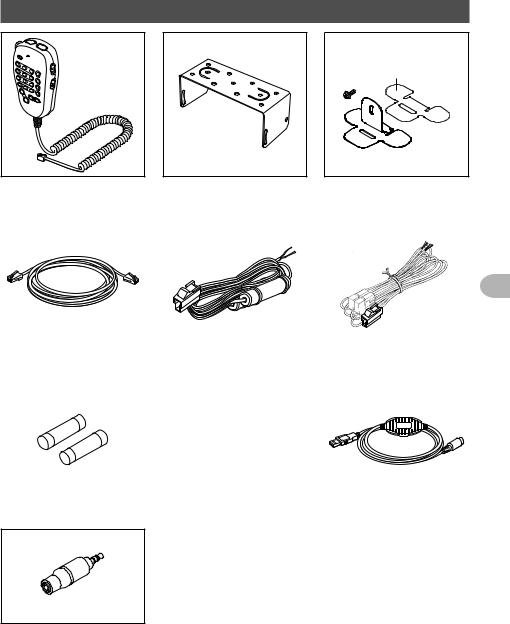
Checking the supplied items
DOUBLE-SIDED
ADHESIVE SHEET
DTMF microphone |
|
Bracket for main body |
|
Bracket for the |
MH-48A6JA |
|
MMB-36 |
|
controller |
|
|
Attachment screw set |
|
|
|
|
|
|
|
|
|
|
|
|
Controller cable |
|
DC power cable |
DC power cable |
|
(3 m) |
|
(with fuse attached) |
(with fuse attached) |
|
|
|
(USA, Asian version) |
(European version) |
|
|
|
|
|
|
|
|
|
|
|
<![endif]>Use Before
Spare fuse (15 A) |
Spare fuse (15 A) |
PC connection cable |
(USA, Asian version) |
(European version) |
SCU-20 |
Operating Manual (this manual)
Warranty Card
Stereo to monaural plug
9
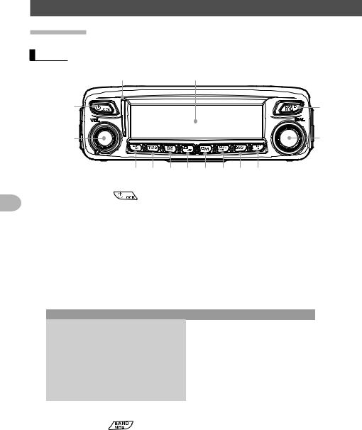
Name and function of each component
Front panel
Front
|
|
|
|
|
|
|
|
|
Power/LOCK key ( |
) |
|
| <![if ! IE]> <![endif]>Before |
Pressing the key for over 2 seconds switches the power between ON and OFF. |
||
Briefly pressing the key while the transceiver is turned ON engages or releases the |
|||
|
|||
|
key lock. |
|
|
| <![if ! IE]> <![endif]>Use |
VOL knob |
|
|
Turning the knob clockwise increases the volume, whereas turning it |
|||
counterclockwise decreases the volume.
Mode/Status indicator
Indicates the transmission/reception status with a two-color combination on the upper and lower portions of the mode/status indicator.
|
Communication status |
Upper portion |
Lower portion |
|
|
Receiving analog audio |
Green |
Green |
|
|
Transmitting analog audio |
Red |
Red |
|
|
Receiving digital audio |
|
Green |
Blue |
|
Transmitting digital audio |
Red |
Blue |
|
|
Receiving digital data |
|
Green |
White |
|
Transmitting digital data |
Red |
White |
|
|
Receiving signals with unmatched |
Green |
Blink in blue |
|
|
tone frequency or DCS code |
|||
|
|
|
||
Dot matrix LCD display |
|
|
|
|
BAND MHz key ( |
) |
|
|
|
Switches each band between the operating band and sub-band.
Pressing and holding for over one second allows you to set the frequency in 1 MHz units.
DIAL knob
•Allows you to set the operating band frequency.
Turning clockwise increases the frequency whereas turning counterclockwise decreases the frequency.
10
Name and function of each component
•Allows you to select the desired item for setup, memory registration, group monitoring operation, etc.
A/B DW key (


 )
)
Briefly pressing each time switches the operating band between Band A and Band B. Pressing for over one second each time switches the dual watch function between ON and OFF.
TXPO key (


 )
)
Briefly pressing each time switches the transmission power (HIGH/MID/LOW). Pressing and holding for over one second each time switches the signaling setting. For details, refer to the Advanced Manual (download from the Yaesu website).
V/M MW key (


 )
)
Briefly pressing each time switches between VFO mode and memory mode. Pressing and holding for over one second displays the memory registration screen.
D/X key (

 )
)
Briefly pressing each time switches the operating band communication mode.
Tip For details on the communication mode, see “Selecting communication mode” on page 29.
Pressing and holding for over one second activates WIRES-X.
GM key (

 )
)
Activates the GM (group monitor) function.
Pressing and holding for over one second displays the DG-ID SETUP screen.
Tip Press the 


 , (
, (


 appears on the left side) on the DG-ID SETUP screen displays the logging function screen. (see “Digital Group ID (DG-ID) function” on page 37.)
SQL VOICE key (


 )
)
Pressing this button briefly and rotating the DIAL sets the squelch level.
Pressing and holding for over one second activates VOICE mode (when the optional FVS-2 is mounted).
BACK key (


 )
)
Briefly pressing enables the selected item or value. Then, the display returns to the previously viewed screen.
DISP SETUP key (


 )
)
Briefly pressing switches the display information (your location information/received station location information/GPS INFO screen).
Tip For details on the display information, see page 15.
Pressing and holding for over one second displays the Setup menu.
<![endif]>Use Before
11
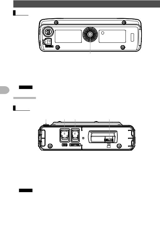
Name and function of each component
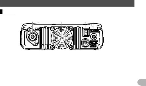
Rear
<![endif]>Use Before
|
|
|
CONTROL jack
Connect the control cable into this jack to connect to the main body.
Screw hole to attach the mounting bracket
Firmware update switch
Caution Keep the rubber cap on when not in use.
Main body
Front
|
|
|
|
MIC jack
Connect the provided microphone cable.
CONTROL jack
Connect the control cable into this jack to connect to the controller.
micro-SD memory card slot
Firmware update switch
Caution Keep the rubber cap on when not in use.
12
|
|
Name and function of each component |
|
Rear |
|
|
|
|
|
|
|
|
|
|
|
ANT terminal Connect the antenna.
13.8V DC
Connect the provided DC power supply cable (with fuse attached).
EXT SP jack
Connect the optional external speaker.
DATA jack
Connect a cable for remote operation or a cable for connecting to devices such as your computer interface unit and the external terminal unit.
Cooling fan
<![endif]>Use Before
13

<![endif]>Use Before
Name and function of each component
Microphone (MH-48A6JA)
MIC
|
ABC |
DEF |
|
LOCK |
1 |
2 |
3 |
A |
|
GHI |
JKL |
MNO |
|
|
4 |
5 |
6 |
B |
LAMP |
7 |
8 |
9 |
C |
|
PQRS |
TUV |
WXYZ |
|
|
|
0 |
|
D |
|
P1 |
|
P3 |
P4 |
|
|
P2 |
|
|
|
DTMF MICROPHONE
MH-48
Increases the frequency by one step.
Decreases the frequency by one step.
Locks / unlocks the [UP] and [DWN] keys and [P1] to [P4] keys.
Turns the lamp on the body of the microphone on/off.
[MIC] Speak into this part during transmission.
[1] to [0] Enters the numbers.
[ ] Switches between VFO and Memory operating mode of the operating band.
[#] |
Activates the GM (Group Monitor) functions. |
[A] |
Switches the operating band to the A-band. |
[B] |
Switches the operating band to the B-band. |
[C] |
Adjusts the squelch level. |
[D] |
Switches the display. |
[P1] |
Turns off the squelch function. |
|
(T.CALL: European version) |
[P2] |
Recalls the receiver home channel. |
[P3] |
Changes the communication mode. |
[P4] |
Changes the transmit power. |
[PTT] |
Switches the transceiver to transmission mode. |
Tip
The desired functions can be assigned to buttons [P1] to [P4]. For details, refer to the Advanced Manual (download from the Yaesu website).
14
Name and function of each component
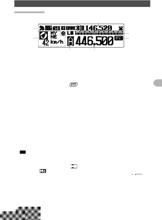
Screen display
|
|
|
|
Icon display
Displays the Bluetooth, APRS, micro-SD memory card and GPS icons when each function is in use.
Station location information display |
|
|
|
Displays the received station’s location information and your station location |
|
||
information. Briefly pressing the |
key each time switches the displayed data |
<![if ! IE]> <![endif]>Before |
|
between the received station location, and your station location. |
|||
|
|||
Sub-band frequency display |
|
|
|
While in VFO mode, displays the sub-band name (A or B) and sub-band frequency. |
<![if ! IE]> <![endif]>Use |
||
While in memory mode, displays the registered frequency or memory tag. |
|||
S-meter display
Displays the S-meter bar graph. Displays the squelch level while adjusting the squelch.
Functions as a power indicator during transmission.
Communication mode display
Displays the current operating mode, such as analog and digital using abbreviations. Auto mode is indicated with a flashing bar appearing above the abbreviation. In Auto mode, the communication mode is automatically set according to the receiving signal.
Tip The AMS functions can be changed in the Setup menu from [2 TX/RX] → [3 AMS TX MODE].
Indicates the operating band name, memory channel, and transmission. When in VFO mode, the operating band name (A or B) is displayed.
While in memory mode, displays 


 and the memory channel number for the
A-band, and |
and the memory channel number for the B-band. |
When transmit is keyed, 

 indicates the “LO” level transmit power, and


 indicates the “MID” level transmit power.
Frequency display
Displays the operating band frequency.
15

Name and function of each component
● GPS INFO screen
While a received station’s information is displayed, briefly press the 


 key to display the GPS INFO screen.
May also display the compass and the signal level of each acquired satellite. □ indicates an un-acquired satellite and ■ indicates an acquired satellite.
Tip From [1 DISPLAY] → [4 GPS INFORMATION], you can select “LOCATION” (location display) or “FREQUENCY” (frequency display).
[Location display]
[Frequency display]
<![endif]>Use Before
Input characters
You can input letters and characters to enter your call sign and memory channel tags by following the procedure below.
Switching the character type
Press 


 (
(


 appears on the upper display). Pressing each time changes the
character type in the following order.
Uppercase letters → symbols → lowercase letters → numbers
Deleting the input characters
Press 


 (
(


 appears on the upper display).
Deletes all characters to the right side of the cursor including the character on which the cursor is currently positioning.
Moving the cursor to the left
Press 

 (
(
 appears on the upper display).
Moving the cursor to the right
Press 

 (
(
 appears on the upper display).
Deleting the most recently input character
Press 


 (
(

 appears on the upper display).
Completing input
Press 


 . To cancel inputting, press


 .
.
16

Installation and Connection
Installing the transceiver
Precautions on installation
Note the following when installing the transceiver.
Do not install the transceiver in a place where it would be exposed to direct sunlight, high temperatures, excessive humidity, dusty conditions, or extreme vibrations.
Install the transceiver in a well-ventilated position, so that heat dissipation is not hindered, because the heat sinks will become hot when the transceiver is run for an extended period of time.
Do not place any objects on the transceiver.
Do not attempt to lift the front panel by holding onto just the knob or control cable. This transceiver requires a 13.8 V DC power supply.
When using this transceiver in a mobile unit, ensure that the car battery is a 12 V type. Never connect this transceiver to a 24 V battery of a large vehicle.
Never connect the transceiver to a 100 V AC power source.
Heed caution as hum and noise may be introduced, depending on the installation conditions of the external power source.
Install the transceiver as far away as possible from TVs and radios. Failing to do so
may result in noise interference such as broadcast interference (BCI) or television
interference (TVI) from radios and TVs respectively. Installation Never attempt to install this transceiver near indoor antenna elements.
<![if ! IE]><![endif]>Connection and
17
<![endif]>Connection and Installation
Installing the transceiver
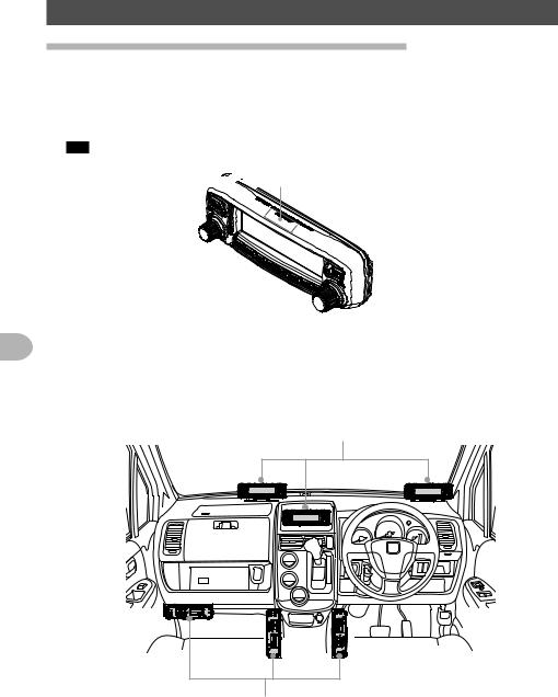
Installation location when used in a mobile unit
● Front panel
To efficiently receive the GPS satellites, it is recommended that the transceiver should be installed on the dashboard or front side of the center console. See “Installing the front panel” on page 21.
Tip The GPS reception antenna is built into the front panel.
Where the GPS antenna


 is built in
● Main body
It is recommended that the main body be installed below the car dashboard or to either side of the center console. See “Installing the main body” on page 20.
Controller
Transceiver main body
18
Installing the transceiver
About the antenna
The antenna is an extremely important part for both transmitting and receiving. The antenna type and its inherent characteristics determine whether the performance of the transceiver can be fully realized. As such, please note the following:
Use an antenna that is suitable for the installation conditions and application objective.
Use an antenna that is suitable for the operating frequency band.
Use an antenna and a coaxial cable with a characteristic feed point impedance of
50Ω.
Adjust the VSWR (Voltage Standing Wave Ratio) until it is 1.5 or less for an antenna with an adjusted impedance of 50Ω.
Keep the coaxial cable routing length as short as possible.
Installing the antenna
● Antenna installation in a mobile unit
Install the antenna base to the rear of the car (rear bumper, trunk, rear gate, etc.) and then attach the antenna to the base.
Cautions
zVerify that the antenna base is securely grounded to the car body.
zWhen using a coaxial cable included with a commercially-available on-vehicle antenna, lay the cable in a way to keep it as short as possible.
zDo not allow rain water or moisture to penetrate the entrance of the cable or connectors when routing the coaxial cable inside the vehicle.
●Antenna installation when using a fixed station
For use in an outdoor setting, there are omni-directional antennas and a variety of directional antennas.
•Omni-directional antennas such as the GP (Ground Plane) antenna are suitable for communications with a local station or mobile stations in all directions.
•Directional antennas such as the Yagi antenna are suitable for communications with a specific station or a remote station in a specific direction.
Cautions
zCreate a loop (slack) in the coaxial cable directly underneath the antenna and fasten the coaxial cable so that the weight of the cable does not pull on the antenna.
zWhen installing the antenna, take into consideration the securing supports and how the guy wires are positioned, so that the antenna does not fall over or get blown away by strong wind gusts.
<![endif]>Connection and Installation
19
<![endif]>Connection and Installation
Installing the transceiver
Installing the main body
Install the main body using the supplied MMB-36 bracket.
1 Select the installation location.
Caution Select a location where the transceiver can be securely attached.
Tip See “Installation location when used in a mobile unit” on page 18.
2Drill four 6 mm diameter holes in the location where the bracket is to be mounted, matching the positions of the bolting holes of the bracket.
3 Attach the bracket. |
|
Attach the bracket using the supplied bolts, nuts |
Nut |
and washers. |
|
Washer |
|
Washer |
Bracket |
|
|
Bolt |
|
4Attach the main body to the bracket.
Fasten the main body to the bracket, using the
supplied flange bolts, as shown in the illustration.
Tip The mounting angle can be changed depending on the securing position of the flange bolts.
Main body |
Flange bolt |
20
Installing the transceiver
Installing the front panel
Install the front panel using the supplied bracket.
Caution
The bracket can be formed by hand to match the location where the front panel is installed. Be careful not to cause an injury when bending the bracket.
1 Select the installation location.
Caution Select a stable, flat location with as few dents and protrusions as possible.
Tip See “Installation location when used in a mobile unit” on page 18.
2Attach the bracket to the front panel.
Attach the bracket to the front panel using the supplied screws as shown in the illustration.
3Adhere double-sided adhesive sheet to the bracket.
Peel off the protection tape from one side of the supplied double-sided adhesive sheet, and paste it onto the bottom side of the bracket.
Controller |
|
|
Bracket |
|
|
Screw |
|
|
Double-sided |
Protection |
<![if ! IE]> <![endif]>Installation |
|
||
adhesive |
|
|
tape |
|
|
sheet |
|
|
|
<![if ! IE]> <![endif]>Connection and |
|
|
|
4 Install the bracket where you want to place the |
|
|
front panel. |
|
|
After the adhesive sheet is adhered to the bottom |
|
|
side of the bracket, Peel off the other side of the |
|
|
protection tape, and then stick the bracket to the |
|
|
installation location. |
|
|
Caution Remove all dirt and dust from the installation |
Protection tape |
|
location before affixing the bracket. |
||
|
21

<![endif]>Connection and Installation
Connecting the transceiver
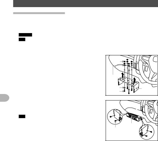
Connecting the front panel to the main body
Caution
Make sure to turn the transceiver OFF before connecting.
1 Connect the supplied control cable to the transceiver main body.
Push the control cable plug into the CONTROL jack on the front panel of the transceiver main body, until it clicks.


 Main
Main
body
Control 

 cable
cable
2Connect the other side of the front panel to the control unit.
Push the other control cable plug into the CONTROL jack on the transceiver control front panel, until it clicks.
Connecting the microphone
1Connect the supplied microphone to the main body.
Plug the microphone connector into the MIC jack
on the front panel until it clicks.
Tips • When disconnecting the microphone, pull the cable while pressing the connector latch.
•Use the optional microphone extension kit “MEK-
2”. An extension cable (Approx. 3 m) is supplied with MEK-2 allowing you to operate further away from the main body.
Front panel |
Control cable |
|
|
MIC |
|
|
|
ABC |
DEF |
|
LOCK |
1 |
2 |
3 |
A |
|
GHI |
JKL |
MNO |
|
|
4 |
5 |
6 |
B |
|
PQRS |
TUV |
WXYZ |
|
LAMP |
7 |
8 |
9 |
C |
|
|
0 |
|
D |
|
P1 |
|
P3 |
P4 |
|
Microphone |
P2 |
|
|
|
DTMF MICROPHONE |
|
|
||
|
MH-48 |
|
|
|
Connector |
|
|
|
|
Connecting the antenna
1Connect the coaxial cable to the main body. Plug the coaxial cable jack into the ANT terminal on the rear panel of the main body, then rotate and tighten it.
Main body |
(rear panel) |
Coaxial cable jack |
22
 Loading...