


HF/50 MHZ TRANSCEIVER
FT-450D
OPERATION MANUAL
VERTEX STANDARD CO., LTD.
4-8-8 Nakameguro, Meguro-Ku, Tokyo 153-8644, Japan
VERTEX STANDARD
US Headquarters
10900 Walker Street, Cypress, CA 90630, U.S.A.
YAESU UK LTD.
Unit 12, Sun Valley Business Park, Winnall Close
Winchester, Hampshire, SO23 0LB, U.K.
VERTEX STANDARD HK LTD.
Unit 5, 20/F., Seaview Centre, 139-141 Hoi Bun Road,
Kwun Tong, Kowloon, Hong Kong
VERTEX STANDARD (AUSTRALIA) PTY., LTD.
Normanby Business Park, Unit 14/45 Normanby Road Notting Hill 3168, Victoria, Australia

TABLE OF CONTENTS
GENERAL FEATURE ........................................... |
1 |
FRONT PANEL BUTTONS AND KNOBS............ |
2 |
DISPLAY INDICATIONS ....................................... |
6 |
REAR PANEL JACKS .......................................... |
8 |
SUPPLIED MH-31A8J MICROPHONE ................. |
9 |
ACCESSORIES & OPTIONS ............................. |
10 |
INSTALLATION .................................................. |
11 |
CONNESTION OF ANTENNA AND POWER SUPPLY .. |
11 |
ABOUT COAXIAL CABLE ............................................... |
12 |
GROUNDING ................................................................... |
12 |
VL-1000 LINEAR AMPLIFIER INTERCONNECTIONS .. |
13 |
INTERFACING TO OTHER LINEAR AMPLIFIER ........... |
13 |
EASY OPERATION ............................................ |
14 |
HOW TO USE THE [DSP/SEL] KNOB ............................ |
15 |
MENU OPERATION ......................................................... |
15 |
HOW TO USE THE [VOICE/C.S] SWITCH .................... |
16 |
KEY DURATION SETTING .............................................. |
17 |
RESETTING THE MICROPROCESSOR ........................ |
18 |
RECEIVING ........................................................ |
19 |
TUNING STEPS ............................................................... |
19 |
CHANGE THE TUNING STEP |
|
OF THE [MAIN DIAL] KNOB ..................... |
19 |
CHANGE THE TUNING STEP |
|
OF THE [DSP/SEL] KNOB ........................ |
19 |
ABOUT THE [UP]/[DWN] BUTTONS |
|
OF THE MH-31A8J ........... |
20 |
CLARIFIER....................................................................... |
20 |
DIGITAL VOICE ANNOUNCEMENT ............................... |
21 |
DIAL LOCK ....................................................................... |
21 |
MY BANDS OPERATION ................................................ |
22 |
MY MODES OPERATION ............................................... |
23 |
DIGITAL VOICE RECORDER ......................................... |
24 |
CONVENIENCE FEATURES ............................. |
25 |
RECEIVER OPERATION |
|
(FRONT END BLOCK DIAGRAM) ......................................... |
25 |
IPO/ATT |
|
(ADJUST THE RECEIVING SENSITIVITY) .................................. |
26 |
NOISE BLANKER |
|
(INTERFERENCE REJECTION “SIGNALS WITHIN 3 kHz”) ........... |
26 |
AGC |
|
(TOOL FOR COMFORTABLE AND EFFECTIVE RECEPTION) ......... |
27 |
CONTOUR |
|
(INTERFERENCE REJECTION “SIGNALS WITHIN 3 kHz”) ........... |
28 |
SHIFT |
|
(INTERFERENCE REJECTION “SIGNALS WITHIN 3 kHz”) ........... |
29 |
WIDTH |
|
(INTERFERENCE REJECTION “SIGNALS WITHIN 3 kHz”) ........... |
30 |
NOTCH |
|
(INTERFERENCE REJECTION “SIGNALS WITHIN 3 kHz”) ........... |
31 |
DNR |
|
(INTERFERENCE REJECTION “SIGNALS WITHIN 3 kHz”) ........... |
32 |
RF GAIN ........................................................................... |
33 |
Using the Automatic Antenna Tuner ............... |
34 |
ATU Operation ................................................................. |
34 |
About ATU Operation ....................................................... |
35 |
SSB/AM MODE TRANSMISSION ..................... |
36 |
TX METER SELECTION ................................................. |
37 |
TX POWER ADJUSTMENT ............................................ |
37 |
TRANSMITTER TIME-OUT TIMER (TOT) ...................... |
38 |
MICROPHONE GAIN LEVEL ADJUSTMENT ................ |
39 |
DSP MICROPHONE EQUALIZER .................................. |
40 |
AUTOMATIC TX/RX SWITCHING |
|
USING VOICE CONTROL (VOX) ........................... |
41 |
MONITOR ........................................................................ |
42 |
SPLIT-FREQUENCY OPERATION ................................. |
43 |
QUICK SPLIT OPERATION ............................................ |
43 |
VOICE MEMORY (SSB/AM/FM MODES) ...................... |
44 |
CW MODE OPERATION .................................... |
46 |
SETUP FOR STRAIGHT KEY |
|
(AND STRAIGHT KEY EMULATION) OPERATION ..... |
46 |
USING THE BUILT-IN ELECTRONIC KEYER ................ |
47 |
CW SPOTTING (ZERO-BEATING) ................................. |
49 |
USING CW REVERSE .................................................... |
49 |
CW DELAY TIME SETTING ............................................ |
50 |
CW SIDETONE VOLUME LEVEL SETTING .................. |
50 |
CW PITCH ADJUSTMENT .............................................. |
51 |
CW TRAINING FEATURE ............................................... |
51 |
BEACON FEATURE ........................................................ |
52 |
FM MODE OPERATION ..................................... |
54 |
BASIC OPERATION ........................................................ |
54 |
REPEATER OPERATION ................................................ |
55 |
TONE SQUELCH/DCS OPERATION .............................. |
56 |
TONE SEARCH SCANNING ........................................... |
57 |
MEMORY OPERATION ...................................... |
58 |
CONVENIENT MEMORY FUNCTIONS .......................... |
58 |
MEMORY GROUPS......................................................... |
59 |
REGULAR MEMORY OPERATION ................................ |
60 |
MEMORY STORAGE ................................................ |
60 |
MEMORY CHANNEL RECALL ................................. |
60 |
ERASING MEMORY CHANNEL DATA ..................... |
61 |
MEMORY TUNE OPERATION .................................. |
61 |
LABELING MEMORIES ............................................ |
62 |
HOME CHANNEL MEMORIES ....................................... |
64 |
HOME CHANNEL RECALL ....................................... |
64 |
HOME CHANNEL FREQUENCY CHANGE ............. |
64 |
QMB (QUICK MEMORY BANK) ...................................... |
65 |
STORAGE ................................................................. |
65 |
RECALL ..................................................................... |
65 |
SCANNING OPERATION ................................... |
66 |
VFO AND MEMORY SCANNING .................................... |
66 |
PREPARATION ......................................................... |
66 |
VFO/MEMORY SCAN ............................................... |
67 |
PROGRAMMABLE MEMORY SCANNING |
|
(PMS) ........ |
68 |
OPERATION ON ALASKA |
|
EMERGENCY FREQUENCY: 5167.5 kHz |
|
(U.S. Version Only)........... |
69 |
MISCELLANEOUS SETTINGS.......................... |
70 |
DISPLAY SETTING.......................................................... |
70 |
BEEPER SETTING .......................................................... |
71 |
BEEP VOLUME ......................................................... |
71 |
BEEP TONE .............................................................. |
72 |
AUTOMATIC POWER-OFF (APO) .................................. |
73 |
Disposal of your Electronic and Electric Equipment
Products with the symbol (crossed-out wheeled bin) cannot be disposed as household waste.
Electronic and Electric Equipment should be recycled at a facility capable of handling these items and their waste byproducts.
In EU countries, please contact your local equipment supplier representative or service center for information about the waste collection system in your country.

TABLE OF CONTENTS
RTTY (RADIO TELETYPE) OPERATION.......... |
74 |
SETTING UP FOR RTTY OPERATION .......................... |
74 |
BASIC SETUP ................................................................. |
74 |
PACKET OPERATION ....................................... |
75 |
PACKET SETUP |
|
(INCLUDING SUBCARRIER FREQUENCY) ........... |
75 |
BASIC SETUP ................................................................. |
75 |
MISCELLANEOUS AFSK-BASED |
|
DATA MODES................. |
76 |
MENU MODE ..................................................... |
78 |
USING THE MENU .......................................................... |
78 |
MENU MODE RESET ...................................................... |
78 |
CLONING ........................................................... |
88 |
INSTALLATION OF |
|
OPTIONAL ACCESSORIES .................... |
90 |
AUTOMATIC-MATCHING 200-MEMORY |
|
ANTENNA TUNER FC-40 OPERATION ....................... |
90 |
ACTIVE-TUNING ANTENNA SYSTEM |
|
(ATAS-100/-120/120A) OPERATION .................... |
92 |
CARRYING HANDLE MHG-1 INSTALLATION ............... |
94 |
MOUNTING BRACKET |
|
MMB-90 INSTALLATION ............................ |
95 |
SPECIFICATIONS .............................................. |
96 |
FCC NOTICE ...................................................... |
98 |
Congratulations on the purchase of your Yaesu amateur transceiver! Whether this is your first rig, or if Yaesu equipment is already the backbone of your station, rest assured that your transceiver will provide many hours of operating pleasure for years to come.
GENERAL FEATURES
Super Compact HF Transceiver with IF-DSP
Built-in ATU (automatic antenna tuner)
Great HF radio performance, with uncomplicated operation, is realized with the very small FT-450D HF transceiver.
HF + 50 MHz with 100 Watts output all mode operation
Small, compact and light-weight HF radio, 9 (W) x 3.3 (H) x 8.5 (D) in, 8.8 lb
Large 9-segment LCD display characters, provide easily read frequency indication
Black-Nega type LCD
Illumination Button
Built-in IF DSP unit that performs all of the following functions:
Modulation and Demodulation
CONTOUR
MANUAL NOTCH
DNR
WIDTH (CW narrow 300 Hz operation available without any optional filters)
Microphone equalizer built in
Speech Processor
DSP VOX operation
Two Voice memory channels included
Frequency read out function
TCXO built-in
500 memory channels
IF SHIFT
IPO
20 dB ATT built-in
Clarifier
Electronic keyer built-in
Microphone and phone jacks on the front panel
FSK-RTTY TX operation
Long wire antenna can be used by the optional FC-40
FT-450D OPERATION MANUAL |
Page 1 |
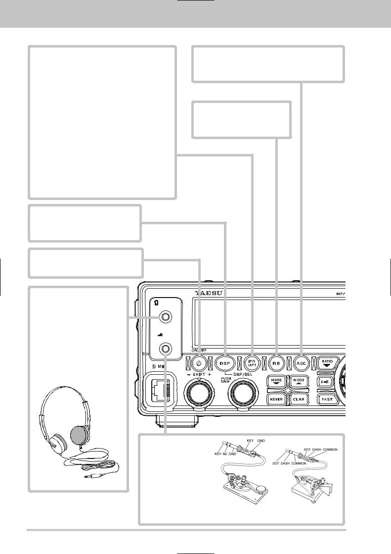
FRONT PANEL BUTTONS AND KNOBS
IPO/ATT Button
This button selects the IPO or ATT feature. Available selections are:
ATT:OFF/IPO:OFF ATT:OFF/IPO:ON
ATT:ON/IPO:OFF ATT:ON/IPO:ON
ATT:OFF/IPO:OFF
IPO: OFF, ATT: OFF
Attenuator is OFF, and the RF preamplifier amplifies the incoming signal.
IPO: ON, ATT: OFF
Attenuator is OFF, and the received signal bypasses the RF preamplifier, yielding a direct feed to the first mixer.
IPO: OFF, ATT: ON
The received signal is reduced by 20 dB, and the RF preamplifier amplifies the incoming signal.
IPO: ON, ATT: ON
The received signal is reduced by 20 dB, and the incoming signal bypasses the RF preamplifier, yielding a direct feed to the first mixer.
The selection will be indicated in the Block Diagram on the display.
AGC Button
This button selects the AGC characteristics for the receiver. Press and hold in this button for one second to disable the AGC (for testing or weak-signal reception).
NB Button
This button turns the IF Noise Blanker on and off. Press this button to reduce short-duration pulse noise.
DSP Button
This button selects the DSP functions. Available selections are CONTOUR, NOTCH, DNR, and WIDTH.
ON/OFF Button
Press and hold in this button for one second to turn the transceiver on or off.
PHONE Jack
A 3.5 mm, 3-contact jack accepts either monaural or stereo headphones with 2 or 3-contact plugs. When a plug is inserted, the loudspeaker is disabled.
NOTE:
When wearing headphones, we recommend that you turn the AF GAIN levels down to their lowest settings before turning power on, to minimize the impact on your hearing caused by audio “pops” during switch-on.
PHONES |
KEY |
KEY Jack
This 3.5 mm, 3-contact jack accepts a CW key or keyer paddles (for the built-in electronic keyer), or output from an external electronic keyer. Pinout is shown below. Key up is 5 volts, and key down current is 0.5 mA.
Do not use the plug except the 3.5-mm 3-pin type plug. If the plug in correct size is not used the radio may be harmed or damaged.
Page 2 |
FT-450D OPERATION MANUAL |
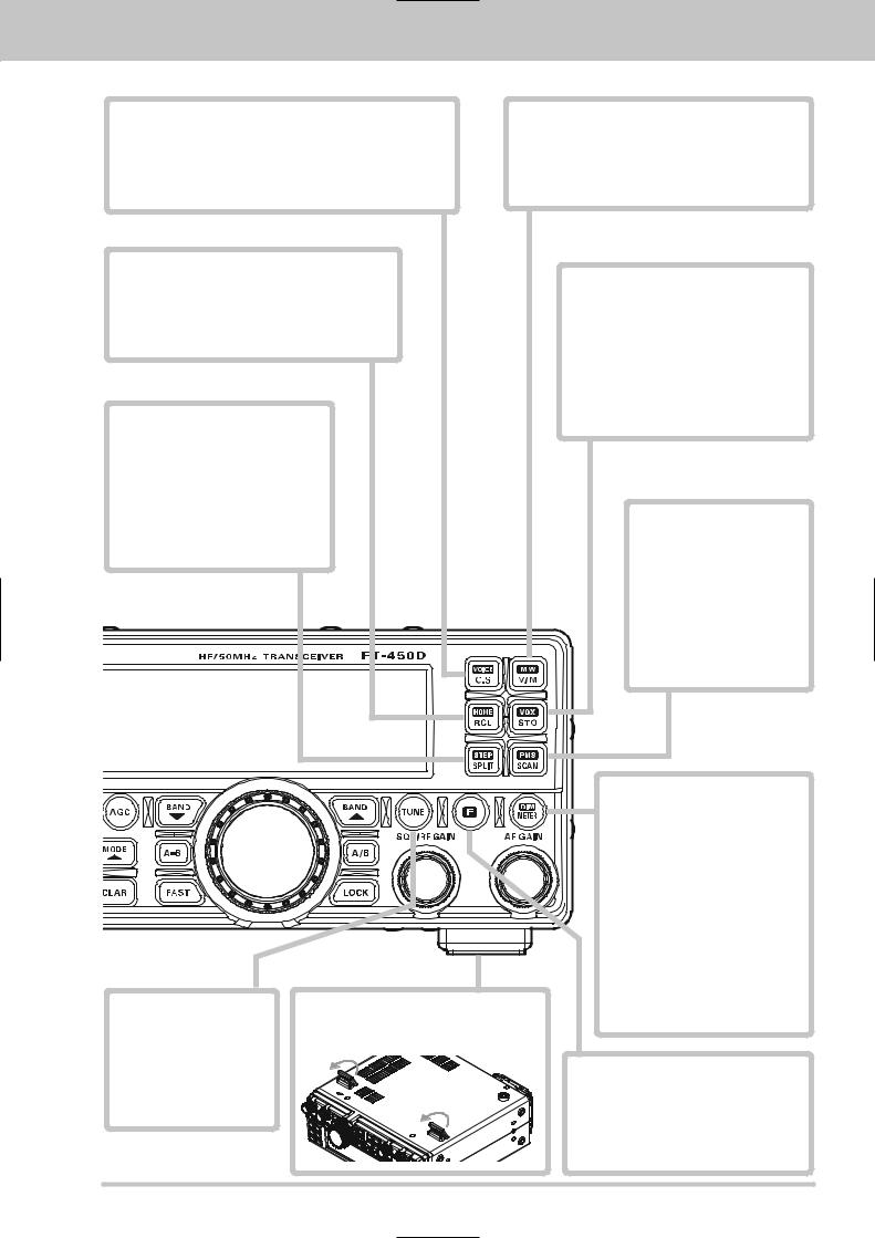
FRONT PANEL BUTTONS AND KNOBS
C.S/VOICE Button
Press this button to activate one of the 52 functions, which can be assigned via Menu Item “PNL-C.S.”
Press the [F] button followed by this button to announce the current operating frequency (with resolution to the displayed 100 Hz digit) and operating mode.
V/M/MW Button
This button toggles frequency control between the VFO and the memory system.
Press the [F] button followed by this button to copy the current operating data from the VFO into the currently selected memory channel.
RCL/HOME Button
Press this button to recall the Quick Memory Bank memory for operation. Press this button again to return to the VFO or Memory mode.
Press the [F] button followed by this button to recall the “Home” (favorite frequency) channel.
SPLIT/STEP Button
Press this button to activate split frequency operation between VFO-A, used for reception and VFO-B, used for transmission (or vice versa).
Press the [F] button followed by this button to enable setting of the frequency step with the [DSP/SEL] knob. When the selection is complete, press this key again.
STO/VOX Button
Press this button to copy the operating information (frequency, mode, bandwidth, and also repeater direction/shift frequency and CTCSS functions on the FM mode) into the Quick Memory Bank.
Press the [F] button followed by this button to activate the VOX (voice-actuated transmitter switching) feature in the SSB, AM, and FM modes.
SCAN/PMS Button
Press this button to initiate the upward scanning of VFO frequencies or memory channels.
Press the [F] button followed by this button to engage the Programmable Memory Scan, (PMS) which limits scanning within a particular frequency range.
TUNE Button
Press this button momentarily to toggle the Internal Automatic Antenna Tuner on/off.
Press and hold in this button to begin the automatic Tuning.
Front Feet
The two front feet allow the transceiver to be tilted upward for better viewing.
METER/DIM Button
Press this button to change the meter function in the transmit mode as follows.
PO ALC SWR PO
PO: Indicates the average power output level.
ALC: Indicates the relative ALC voltage.
SWR: Indicates the Standing Wave Ratio (Forward/Reflected).
Press the [F] button followed by this button to enable adjustment of the display dimmer level by the [DSP/ SEL] knob. When the adjustment is complete, press this key again.
F Button
Press this button to activate the alternate key functions of the six command buttons located on the upper right corner of the front panel.
Press and hold this button for one second to engage the “Menu” mode.
FT-450D OPERATION MANUAL |
Page 3 |
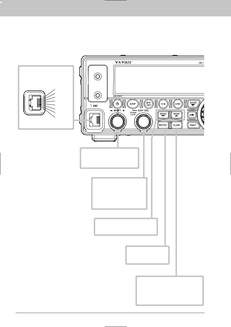
FRONT PANEL BUTTONS AND KNOBS
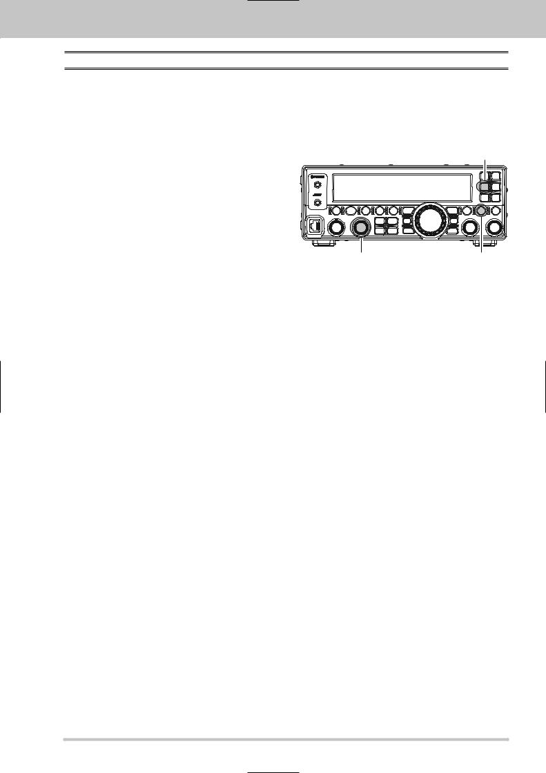
MIC Jack
This 8-pin jack accepts input from a supplied MH-67A8J Hand Microphone.
(viewed from front panel)
 PHONES
 KEY
KEY
SHIFT Knob
This knob shifts the IF DSP passband to reduce an interfering signal which is inside the IF passband.
DSP/SEL Knob
This knob is used to select functions depending on the situation.
Frequency Tuning
Memory Channel Selection
DSP Setting
Menu Mode Selection
MODE /MODE Button
These buttons select the operating mode.
KEYER Button
This button toggles the internal CW keyer on and off.
CLAR Button
Pressing this button activates the Clarifier, to allow temporarily offsetting the receive frequency. When the Clarifier is active, you may offset the receive frequency by adjusting the [MAIN DIAL] knob.
Page 4 |
FT-450D OPERATION MANUAL |
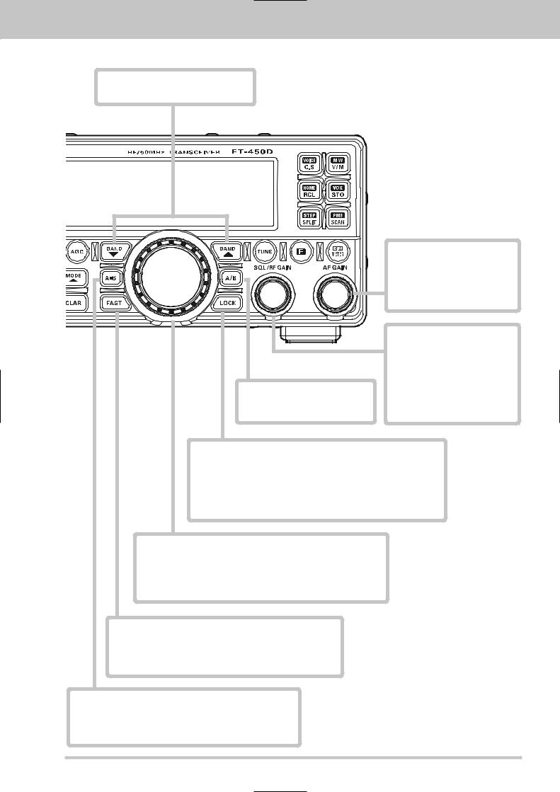
FRONT PANEL BUTTONS AND KNOBS
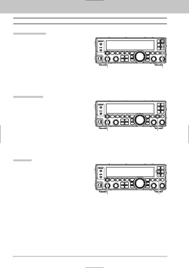
BAND /BAND Button
These buttons select the operating band.
AF GAIN
This knob sets the receiver’s audio volume level. Typically, you will operate with this control set between the 9 o’clock and 10 o’clock positions.
A/B Button
This button toggles the frequency control between VFO-A and VFO-B.
LOCK Button
SQL/RF GAIN Knob
In the factory default, this knob adjusts the gain of the receiver’s RF and IF stages. Using Menu Item “SQL/RFG”, this knob may be changed to function as a Squelch control, which may be used to silence background noise when no signal is present.
This button toggles the locking of the [MAIN DIAL] knob and some switches, to prevent accidental frequency changes.
Advice: You may select the locking schemes via the Menu Mode. Term Explanation: The Menu Mode permits you to make small changes in the parameters of many of the functions of the FT-450D. You can customize the operations to your personal preferences.
MAIN DIAL Knob
This knob adjusts the operating frequency in the SSB/CW/DATA modes. You may change the knob’s function to also adjust frequency in AM/FM mode via the Menu Mode.
When the Clarifier is activated, this knob adjusts the receiver offset frequency.
FAST Button
Pressing this button will increase or decrease the tuning rate of the [MAIN DIAL] knob by a factor of ten and also increase or decrease the tuning rate of the [DSP/SEL] knob by a factor of two.
A=B Button
Press this button momentarily to transfer data from VFO-A frequency (or a recalled memory channel) to VFO-B, overwriting the previous contents in VFO-B. Use this key to set both VFO-A and VFO-B to the same frequency and mode.
FT-450D OPERATION MANUAL |
Page 5 |

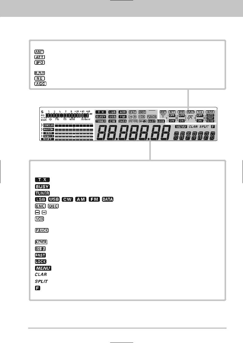
DISPLAY INDICATIONS
Display
 PHONES
 KEY
KEY
Meter
While receiving, the received signal strength is displayed.
While transmitting, the meter displays PO, ALC, or SWR (determined by the [METER/DIM] button).
DSP Graphic Display
:The peak position of the CONTOUR Filter is depicted graphically here when the CONTOUR Filter is activated.
:The null position of the IF Notch Filter is depicted graphically here when the IF Notch Filter is activated.
:Indicates the Noise Reduction level of the Digital Noise Reducer.
:Indicates the bandwidth of the DSP IF filter.
:Indicates the peak position of the DSP IF filter.
Page 6 |
FT-450D OPERATION MANUAL |
DISPLAY INDICATIONS
Block Diagram Display
:Indicates the antenna status. When the antenna system became abnormality, this indicator will blink.
:Indicates the RF attenuator status (“ON” or “OFF”) selected for operation by the [IPO/ATT] button.
:Indicates that the front-end RF pre-amplifier is removed from the receiver circuit. The incoming signal is fed direct to the first mixer.
:Indicates the 10 kHz Roofing Filter status. This is always turned on.
:Indicates the Noise Blanker status (“ON” or “OFF”).
:Indicates the AGC decay time.
Frequency Display
The operating frequency is displayed.
:This indicator appears during transmission.
:This indicator appears whenever the receiver squelch is open.
:This indicator appears when the Internal Automatic Antenna Tuner is activated.
: Displays the currently selected operating mode.
: Displays the current CTCSS operation while in FM mode.
: Displays the Repeater Shift Direction while in FM mode.
:This indicator appears whenever the VOX (automatic voice-actuated transmitter switching) circuit is activated.
:This indicator appears while the voice recorder is recording the receiver audio. This indicator blinks while the voice recorder is playing back the recorded audio.
:This indicator appears whenever the internal CW keyer is activated.
:This indicator appears whenever the CW break-in operation is activated.
:This indicator appears when the [MAIN DIAL] knob’s tuning rate is set to fast.
:This indicator appears when the [MAIN DIAL] knob is locked.
:This indicator appears whenever the Menu Mode is engaged.
:This indicator appears whenever the Clarifier function is activated.
:This indicator appears whenever Split-frequency operation is activated.
:This indicator appears when the alternate key functions of the six command buttons located on the upper right corner of the front panel is activated.
FT-450D OPERATION MANUAL |
Page 7 |
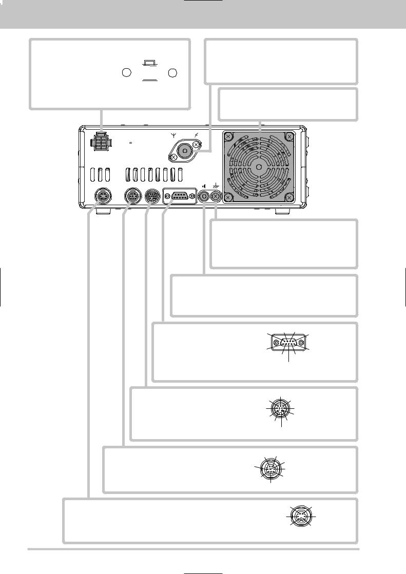
REAR PANEL JACKS
DC IN Jack
This is the DC power supply connection for the transceiver. Use the supplied DC cable to connect directly to the car battery or to a DC power supply, which must be capable of supplying at least 22 A @13.8 VDC.
-  +
+
(viewed from rear panel)
ANT
INPUT DC 13.8V
22A
ANT Jack
Connect your antenna here, using a type-M (PL-259) coaxial connector and 50 Ohm coaxial feedline.
Warning!: High Power RF voltage is present at the TX RF section of the transceiver while transmitting. Absolutely! Do not touch the TX RF section while transmitting.
COOLING FAN
Turns at low speed in receive mode.
Turns at high speed when the temperature begins to rise or in transmit mode.
|
|
EXT |
GND |
|
|
SPKR |
|
DATA |
TUNER LINEAR |
CAT |
|
GND Terminal
For safety and optimum performance, use this terminal to connect the transceiver to a good earth ground. Use a large diameter, short braided cable for making ground connections. Refer to page 12 for other notes about proper grounding.
EXT SPKR Jack
This 3.5-mm, 2-pin jack provides variable audio output for an external speaker. The audio output impedance at this jack is 4 - 16 Ohms and the level varies according to the setting of the front panel’s [AF GAIN] knob. Inserting a plug into this jack disables the internal loudspeaker.
CAT Jack
This 9-pin serial DB-9 jack allows external computer control of the FT450D. Connect a (straight) serial cable here and to the RS-232C COM port on your personal computer (no external interface is required).
N/A |
CTS |
RTS |
|
Connect to |
|
|
|
|
GND |
|
Connect to |
Connect to |
SERIAL OUT |
|
|
SERIAL IN |
|
(viewed from rear panel)
LINEAR Jack
This 10-pin output jack provides band selection data, which may be used for control of the optional VL-1000 SolidState Linear Amplifier.
TUNER Jack
This 8-pin jack is used for Connection to the FC-40 External Automatic Antenna Tuner.
TX GND OUT
+13.8V OUT |
GND |
BAND DATA-A (LSB) |
BAND DATA-D (MSB) |
TX INH IN |
TXREG IN |
|
|
BAND DATA-B |
BAND DATA-C |
|
|
EXT ALC IN |
(viewed from rear panel) |
+13.8V OUT TX GND OUT
RXD
GND
TXD
TUNER SENSE |
TX INH IN |
RESET OUT (viewed from rear panel)
DATA Jack
This 6-pin input/output jack provides receiver audio and squelch signals, and accepts transmit (AFSK) audio and PTT control, from an external packet TNC.
DATA IN |
GND |
DATA PTT |
FSK IN |
DATA OUT |
SQL OUT |
(viewed from rear panel)
Page 8 |
FT-450D OPERATION MANUAL |
SUPPLIED MH-31A8J MICROPHONE
FST (FAST) Key
The FST Button on the transceiver should be set for momentary operation.
DWN Key
Press to tune down, hold to start scanning.
PTT Switch
Press this Switch to transmit, and release it to receive after your transmission is completed.
UP Key
Press to tune up, hold to start scanning.
DWN FST UP
DYNAMIC MICROPHONE
MH-31
MIC
The microphone is located here. Speak into the microphone in a normal voice level. The microphone should be positioned within 2 inches (5 cm) from the mouth for optimum performance.
TONE Switch
Position 1 provides flat-audio- characteristic transmit audio. Position 2 attenuates low audio tones, for improved clarity in moderate band conditions, or if you have a naturally deep voice.
FT-450D OPERATION MANUAL |
Page 9 |

ACCESSORIES & OPTIONS
SUPPLIED ACCESSORIES
Hand Microphone (MH-31A8J) |
1 pc |
P/N: M3090086A |
DC Power Cord with Fuse |
1 pc |
P/N: T9025225 |
Fuse |
1 pc |
P/N: Q0000074 |
Operation Manual |
1 pc |
|
Warranty Card |
1 pc |
|
AVAILABLE OPTIONS
External Automatic Antenna Tuner (for Wire Antenna) |
FC-40 |
Active-Tuning Antenna System |
ATAS-25 |
Active-Tuning Antenna System |
ATAS-120A |
Solid-State Linear Amplifier/AC Power Supply |
VL-1000 / VP-1000 |
Band Data Cable (for VL-1000) |
CT-118 |
Desktop Microphone |
MD-100 |
DTMF Hand Microphone |
MH-36E8J |
Hand Microphone |
MH-31A8J |
Lightweight Stereo Headphone |
YH-77STA |
Mobile Mounting Bracket |
MMB-90 |
Carrying Handle |
MHG-1 |
CT Cable (MDIN10P - Bare Wire 2m) |
Linear Amplifier Connection Cable (P/N T9207451) |
Page 10 |
FT-450D OPERATION MANUAL |
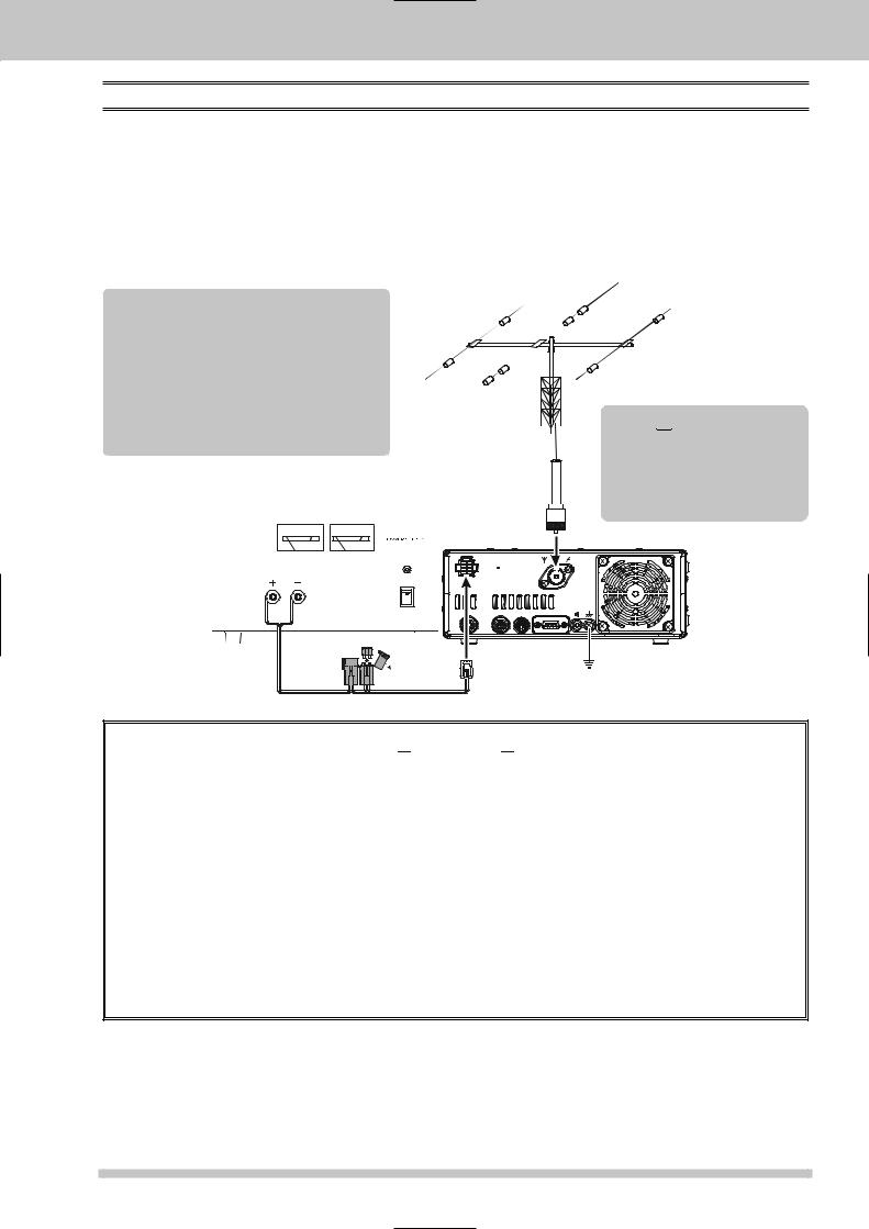
INSTALLATION
CONNECTION OF ANTENNA AND POWER SUPPLY
The FT-450D is designed for use with any antenna system providing a 50 Ohm resistive impedance at the desired operating frequency. Every effort should be made to ensure the impedance of the antenna system is as close as possible to the specified 50-Ohm value. Note that the “G5RV” type antenna does not provide 50-Ohm impedance on all HF Amateur bands, and an external wide-range antenna coupler must be used with this antenna type.
Any antenna to be used with the FT-450D must, ultimately, be fed with 50 Ohm coaxial cable. Therefore, when using a “balanced” antenna such as a dipole, remember that a balun or other matching/balancing device must be used to ensure proper antenna performance.
CAUTION
Permanent damage can result if improper supply voltage, or reverse-polarity voltage, is applied to the FT-450D. The Limited Warranty on this transceiver does not cover damage caused by application of AC voltage, reversed polarity DC, or DC voltage outside the specified range of 13.8V ±10%.
When replacing fuses, be certain to use a fuse of the proper rating. The FT-450D requires a 25A fastblow fuse.
AC Power Supply |
|
|
|
|
ANTENNA |
|
|||||
|
|
|
|
|
|
||||||
0 |
5 |
10 |
15 |
20 |
0 |
5 |
20 |
30 |
40 |
|
|
|
|
V |
|
|
|
|
A |
|
|
|
|
|
|
|
|
|
|
|
|
|
|
ANT |
|
|
|
|
|
|
|
|
|
|
|
INPUT |
|
|
|
|
|
|
|
|
|
|
|
DC 13.8V |
|
|
|
|
|
|
|
|
|
|
|
22A |
|
|
|
|
|
|
|
|
|
|
POWER |
|
|
|
|
|
|
|
|
|
|
|
ON |
|
|
|
|
|
|
|
|
|
|
|
|
EXT |
GND |
|
|
|
|
|
|
|
|
|
OFF |
SPKR |
|
|
|
|
|
|
|
|
|
|
DATA |
TUNER LINEAR CAT |
|
RED BLACK
BLACK

 Warning!
The 100V RF voltage (@100 W/50 Ω) is applied to the TX RF section of the transciver while transmitting.
Do not touch the TX RF section absolutely while transmitting.
FT-450D
FUSE: 25A

 CAUTION

Do not position this apparatus in a location with direct exposure to sunshine.
Do not position this apparatus in a location exposed to dust and/or high humidity.
Do not expose the apparatus to dripping or splashing. Do not put objects with liquids on the apparatus.
Ensure adequate ventilation around this apparatus, so as to prevent heat build-up and possible reduction of performance due to high heat.
Do not install this apparatus in a mechanically-unstable location, or where objects may fall onto this product from above.
To minimize the possibility of interference to home entertainment devices, take all precautionary steps including separation of TV/FM antennas from Amateur transmitting antennas to the greatest extent possible, and keep transmitting coaxial cables separated from cables connected to home entertainment devices.
Be absolutely certain to install your transmitting antenna(s) such that they cannot possibly come in contact with TV/FM radio or other antennas, nor with outside power or telephone lines.
FT-450D OPERATION MANUAL |
Page 11 |
INSTALLATION
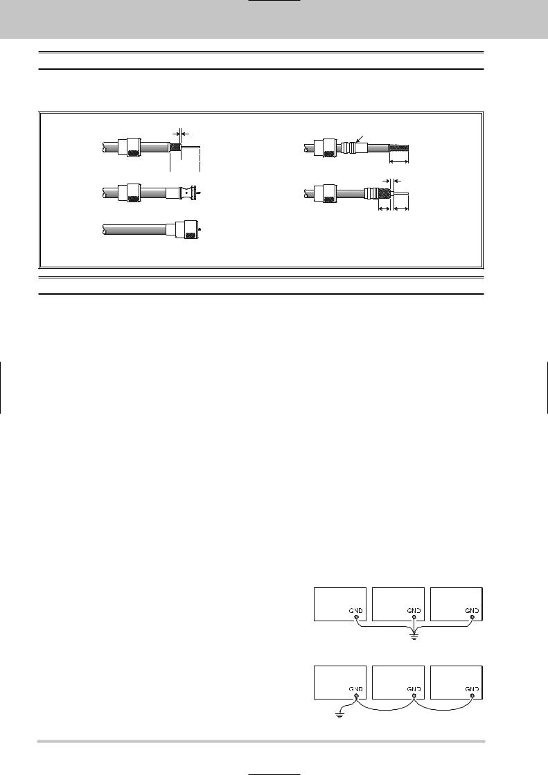
ABOUT COAXIAL CABLE
Use high-quality 50-Ohm coaxial cable for the lead-in to your FT-450D transceiver. All efforts at providing an efficient antenna system will be wasted if poor quality, lossy coaxial cable is used. This transceiver utilizes standard “M” (“PL-259”) type connector.
21/16''mm |
Adapter |

 20 mm
20 mm
3/4''


 203/4''mm 301 1/8''mm
31/8''mm |
10 3/8''mm 155/8''mm
TYPICAL PL-259 INSTALLATION
GROUNDING
The FT-450D transceiver, like any other HF communications apparatus, requires an effective ground system for maximum electrical safety and best communications effectiveness. A good ground system can contribute to station efficiency in a number of ways:
It can minimize the possibility of electrical shock to the operator.
It can minimize RF currents flowing on the shield of the coaxial cable and the chassis of the transceiver.
Such currents may lead to radiation, which can cause interference to home entertainment devices or laboratory test equipment.
It can minimize the possibility of erratic transceiver/accessory operation caused by RF feedback and/or improper current flow through logic devices.
An effective earth ground system may take several forms. For a more complete discussion, see an appropriate RF engineering text. The information below is intended only as a guideline.
Typically, the ground connection consists of one or more copper-clad steel rods, driven into the ground. If multiple ground rods are used, they should be positioned in a “V” configuration, and bonded together at the apex of the “V” which is nearest the station location. Use a heavy, braided cable (such as the discarded shield from type RG-213 coaxial cable) and strong cable clamps to secure the braided cable(s) to the ground rods. Be sure to weatherproof the connections to ensure many years of reliable service. Use the same type of heavy, braided cable for the connections to the station ground bus (described below).
Inside of the station, a common ground bus consisting of a copper pipe of at least 25 mm (1”) diameter should be used. An alternative station ground bus may consist of a wide copper plate (single-sided circuit board material is ideal) secured to the bottom of the operating desk. Grounding connections from individual devices such as transceivers, power supplies, and data communications devices (TNCs, etc.) should be made directly to the ground bus using a heavy, braided cable.
Do not make ground connections from one electrical device to another, and thence to the ground bus. This so-called “Daisy-Chain” grounding technique may nullify any attempt at effective radio frequency grounding. See the drawing at the right for examples of proper grounding techniques.
Inspect the ground system - inside the station as well as outside - on a regular basis so as to ensure maximum performance and safety.
Besides following the above guidelines carefully, note that household or industrial gas lines must never be used in an attempt to establish an electrical ground. Cold water pipes may, in some instances, help in the grounding effort, but gas lines represent a significant explosion hazard, and must never be used.
Transceiver |
Linear |
TNC |
|
Amplifier |
|
PROPER GROUND CONNECTION
Transceiver |
Linear |
TNC |
|
Amplifier |
|
|
"Daisy Chain" |
|
IMPROPER GROUND CONNECTION
Page 12 |
FT-450D OPERATION MANUAL |
INSTALLATION
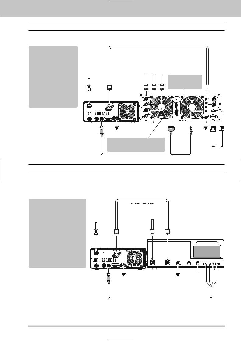
VL-1000 LINEAR AMPLIFIER INTERCONNECTION
Be sure that both the FT-450D and VL-1000 are turned off, then follow the installation recommendations contained in the illustration.
Note
Please refer to the VL-1000 Operating
Manual for details regarding amplifier operation.
Please do not attempt to connect or disconnect coaxial cables when your hands are wet.
DC 13.8 V
INPUT |
ANT |
|
ANT |
INPUT |
|
DC 13.8V |
|
22A |
|
|
|
EXT |
GND |
|
|
SPKR |
|
DATA |
TUNER LINEAR |
CAT |
|
ANTENNA CABLE (Not Supplied)
VerticalAntenna |
DipoleAntenna |
BeamAntenna |
HF |
HF |
HF |
|
|
|
Set the front panel’s |
1 |
2 |
3 |
INPUT switch to the |
ANT |
ANT |
ANT |
“INPUT2”. |
|
|||
ANT 1 |
|
|
|
|
|
|
REMOTE |
|
|
|
ON |
|
|
|
OFF |
ANT 2 |
|
|
BAND DATA 1 |
ANT 3 |
|
|
|
ANT 4 |
|
|
|
|
|
|
BAND DATA 2 |
 INPUT 2
INPUT 1
PTT 1
PTT 2
INPUT 2
ALC 1
CONTROL
ALC 2
DC48V IN
GND
LINEAR |
GND |
To link the FT-450D and VL-1000
Power switches, set the VL-1000 REMOTE switch to the “ON” position.
CT-118 CONNECTION CABLE (Option)
BAND-DATA2 |
ALC2 |
GND |
DC48VIN |
CONTROL |
|
|
|
VP-1000 |
VP-1000 |
INTERFACING TO OTHER LINEAR AMPLIFIER
The T/R control line is a transistor “open collector” circuit, capable of handling positive amplifier relay coil voltages of up to +50V DC and current of up to 400 mA. If you plan on using multiple linear amplifiers for different bands, you must provide external band-switching of the “Lin Tx” relay control line from the “TX GND OUT” line at the LINEAR jack.
Important Note!
Do not exceed the maximum voltage or current ratings for the “TX GND OUT” line at the LINEAR jack. This line is not compatible with negative DC voltages, nor AC voltages of any magnitude.
Most amplifier control relay systems require only low DC voltage/current switching capability (typically, +12V DC at 25 ~ 75 mA), and the switching transistor in the FT-450D will easily accommodate such amplifiers.
DC13.8V |
HFAntenna |
INPUT |
ANT1 |
ANT 1 |
INPUT 1 |
ANT
INPUT DC 13.8V
22A
|
|
|
RF OUT |
RF IN |
|
|
|
|
|
|
|
GND |
FUSE |
AC |
E ALC E RY |
|
|
EXT |
GND |
|
|
|
|
|
|
SPKR |
|
|
|
|
|
DATA |
TUNER LINEAR |
CAT |
|
|
|
|
|
Linear Amplifier Connection Cable (T9207451)
Color Code Information
Wire Color |
LINEA Jack (Pin Number) |
Function |
Orange |
1 |
+13.8 V |
Yellow |
2 |
TX GND OUT |
Green |
3 |
GND |
Red |
4 |
BAND DATA A |
White |
5 |
BAND DATA B |
Blue |
6 |
BAND DATA C |
Violet |
7 |
BAND DATA D |
Brown |
8 |
TX INH |
Black |
9 |
EXT ALC IN |
Gray |
10 |
TX REQ IN |
Light Blue |
Case |
Shield |
LINEAR |
GND |
GND |
Light-Blue |
Black |
Green |
Yellow |
|
|
Linear Amplifier Connection Cable (T9207451: Option) |
|
|
|
|
FT-450D OPERATION MANUAL |
Page 13 |
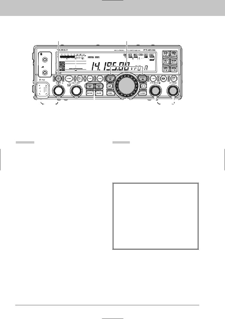
EASY OPERATION
[POWER(ON/OFF)] switch |
[BAND ]/[BAND ] button |
PHONES |
|
KEY |
|
|
|
|
|
|
|
|
|
|
|
|
|
|
|
|
|
|
|
|
|
|
|
|
|
|
|
|
|
|
|
|
|
|
|
|
|
|
|
|
|
|
|
|
|
|
|
|
|
|
|
|
|
|
|
|
|
|
|
|
|
|
|
|
|
|
|
|
|
|
|
|
|
|
|
|
|
|
|
|
|
|
|
|
|
|
|
|
|
|
|
|
|
|
|
|
|
|
|
|
|
|
|
|
|
|
|
|
|
|
|
|
|
|
|
|
|
|
|
|
|
|
|
|
|
|
|
|
|
|
|
|
|
|
|
|
|
|
|
|
|
|
|
|
|
|
|
|
|
|
|
|
|
|
|
|
|
|
|
|
|
|
|
|
|
|
|
|
|
|
|
|
|
|
|
|
|
|
|
|
|
|
|
|
|
|
|
|
|
|
|
|
[MAIN DIAL] knob |
|
|
|
[AF GAIN] knob |
||||
|
|
|
|
|
|
|
|
|
|
|
|
|
|
|
|
|
|
|
|
|||||
|
|
|
|
|
|
|
|
|
|
|
|
|
|
|
[MODE ]/[MODE ] button |
[SQL/RF GAIN] knob |
||||||||
RECEIVING |
TRANSMIT |
1.Connect your antenna to the ANT jack on the rear panel.
2.Connect the after-market DC power supply (or car battery) using the supplied DC power cable, and set the POWER switch of the DC power supply to on.
3.Press and hold in the [POWER(ON/OFF)] switch for one second to turn the transceiver on.
4.Rotate the [SQL/RF GAIN] knob to the fully counter-clockwise position.
5.Rotate the [AF GAIN] knob to set a comfortable audio level on incoming signals or noise. Clockwise rotation of the [AF GAIN] knob increases the volume level.
6.Press the [BAND ]/[BAND ] button to select the amateur band which you wish to begin operating.
7.Press the [MODE ]/[MODE ] button to select the desired operating mode.
8.Rotate the [MAIN DIAL] knob to set the desired frequency.
1.Connect the supplied MH-31A8J to the MIC jack on the front panel.
2.To transmit, press the microphone’s PTT (Push To Talk) switch, speak into the microphone in a normal voice level.
3.Release the PTT switch to return to the receive mode.
NOTICE
Regarding of the [DSP/SEL] knob
The [DSP/SEL] knob is used for operating various functions depending on the situation.
If you can not change the frequency/memory channel by tuning the [DSP/SEL] knob, the [DSP/SEL] knob is selected to operate of one of the DSP functions.
In this case, press the [DSP] button several times until the “>” icon disappears from the
DSP Graphic Display.
Page 14 |
FT-450D OPERATION MANUAL |
EASY OPERATION
HOW TO USE THE [DSP/SEL] KNOB
When a DSP function is not selected and no “>” icon is shown in the LCD Graphic Display, then turning the [DSP/SEL] knob controls the frequency in VFO mode, or selects the memory channel in memory mode, or selects the menu item in memory mode. In the VFO Mode, briefly depressing the [DSP/SEL] knob will permit frequency adjustment in 100 kHz steps (Default setting). (The 100 kHz operation may
be changed with the“SELDIAL” menu function.) |
[DSP/SEL] knob |
|
When a DSP function is selected, the “>” icon will appear next to the function in the LCD Graphic Display. Then pressing the [DSP/SEL] knob will switch the DSP function on or off. When the DSP function is on, turning the [DSP/SEL] knob will change the function parameters.
ADVICE:
You may change the function of the [DSP/SEL] knob via menu item “SELDIAL”.
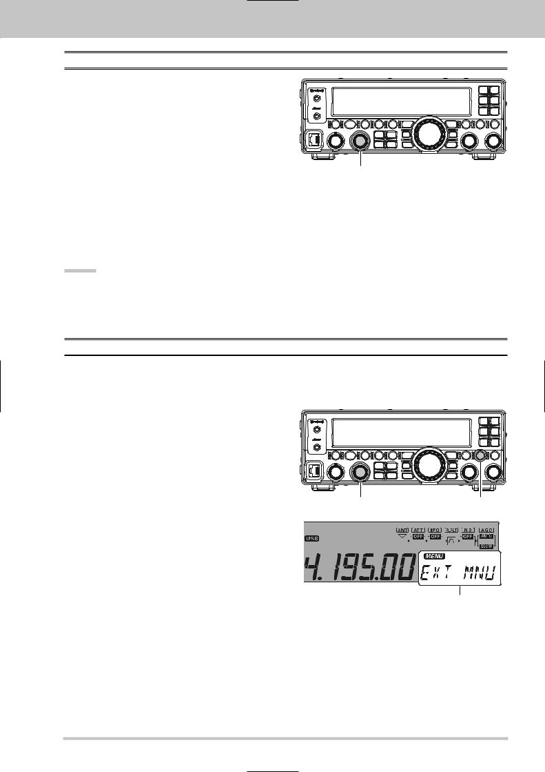
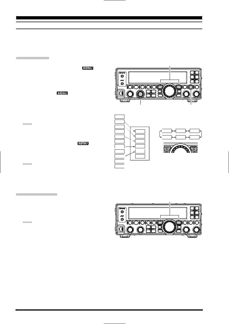
MENU OPERATION
The Menu System allows you to customize a wide variety of transceiver performance aspects and operating characteristics. After you have initially customized the various Menu procedures, you will find that you will not have to resort to them frequently during everyday operation.
1.Press and hold the [F] button for one second to enter the Menu Mode. The “ ” icon will appear on the display.
2.Rotate the [DSP/SEL] knob to select the Menu Item to be adjusted.
3.Press the [DSP/SEL] knob to enable adjustment of the selected Menu Item. The “ ” icon will blink.
4.Rotate the [DSP/SEL] knob to adjust or select the parameter to be changed.
5.Press the [DSP/SEL] knob to save the selection. The icon appears continuously.
6.Press and hold the [F] button for one second to return to normal operation.
[DSP/SEL] knob |
[F] button |
Menu Item or Menu Setting
FT-450D OPERATION MANUAL |
Page 15 |
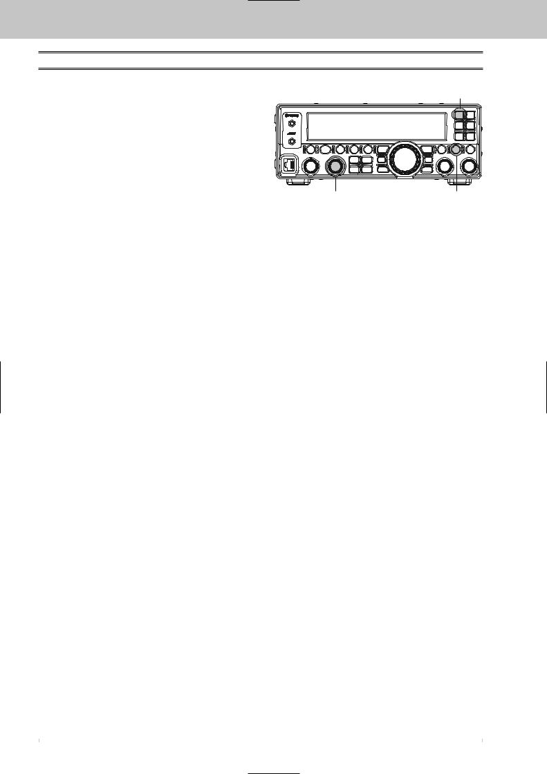
EASY OPERATION
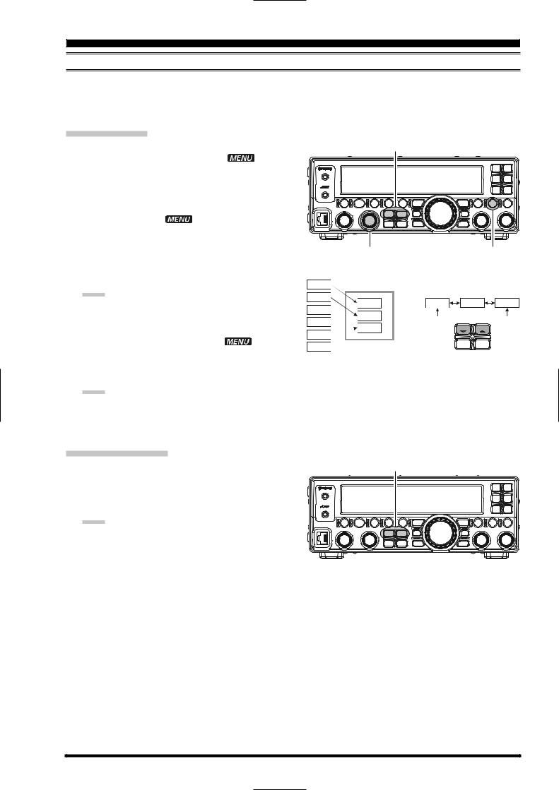
HOW TO USE THE [C.S/VOICE] SWITCH
You may set the [C.S/VOICE] button function to one of 52 functions via Menu Item “PNL-C.S”.
To assign a function to the [C.S/VOICE] button:
1.Press and hold the [F] button for one second to enter the Menu Mode. The “ ” icon will appear on the display.
2.Rotate the [DSP/SEL] knob to select Menu Item “PNL-C.S”.
3.Press the [DSP/SEL] knob to enable adjustment of this Menu Item. The “ ” icon will be blinking.
4.Rotate the [DSP/SEL] knob to select the desired function.
5.Press the [DSP/SEL] knob. The “ ” icon returns to appear continuously.
6.Press and hold the [F] button for one second to return to normal operation.
[C.S/VOICE] button
[DSP/SEL] knob |
[F] button |
Item |
Function |
MONI |
Activates the Monitor function. |
N/A |
No Function. |
P/B |
Activates the Digital Voice Recorder. |
PLAY1 |
Send the CW message, which is memorized in BEACON TEXT 1. |
PLAY2 |
Send the CW message, which is memorized in BEACON TEXT 2. |
PLAY3 |
Send the CW message, which is memorized in BEACON TEXT 3. |
QSPL |
Activates Quick Split Operation |
SPOT |
Generates a CW Spot Tone while pressing the [C.S/VOICE] button when using CW mode. |
SQLOFF |
Opens the noise squelch while pressing the [C.S/VOICE] button. |
SWR |
Transmits a 10 watts carrier (CW mode) to measure the SWR ratio while pressing the [C.S/VOICE] button. |
TXW |
Monitor the transmit frequency while pressing the [C.S/VOICE] button when Split Frequency operation is engaged. |
VCC |
Display the DC supply voltage while pressing the [C.S/VOICE] button. |
VOICE2 |
Announces the current S-meter reading, operating frequency (with resolution to the displayed 100 Hz digit), and |
|
operating mode. |
VM1MONI |
Play back the voice message, which is memorized in Voice Memory 1. |
VM1REC |
Store the voice message into Voice Memory 1. |
VM1TX |
Send the voice message, which is memorized in Voice Memory 1. |
VM2MONI |
Play back the voice message, which is memorized in Voice Memory 2. |
VM2REC |
Store the voice message into Voice Memory 2. |
VM2TX |
Send the voice message, which is memorized in Voice Memory 2. |
DOWN |
Decreases the VFO frequency by one step or moves the memory channel to the next-lowest channel while pressing |
|
the [C.S/VOICE] button. |
FAST |
Set to the same function as the front panel’s [FAST] button. |
UP |
Increases the VFO frequency by one step or moves the memory channel to the next-highest channel while pressing |
|
the [C.S/VOICE] button |
DSP |
Set to the same function as the front panel’s [DSP] button. |
IPO/ATT |
Set to the same function as the front panel’s [IPO/ATT] button. |
NB |
Set to the same function as the front panel’s [NB] button. |
AGC |
Set to the same function as the front panel’s [AGC] button. |
MODEDN |
Set to the same function as the front panel’s [MODE ] button. |
MODEUP |
Set to the same function as the front panel’s [MODE ] button. |
DSP/SEL |
Set to the same function as the front panel’s [DSP/SEL] button. |
KEYER |
Set to the same function as the front panel’s [KEYER] button. |
CLAR |
Set to the same function as the front panel’s [CLAR] button. |
BANDDN |
Set to the same function as the front panel’s [BAND ] button. |
BANDUP |
Set to the same function as the front panel’s [BAND ] button. |
A=B |
Set to the same function as the front panel’s [A=B] button. |
A/B |
Set to the same function as the front panel’s [A/B] button. |
LOCK |
Set to the same function as the front panel’s [LOCK] button. |
TUNE |
Set to the same function as the front panel’s [TUNE] button. |
VOICE |
Announce the current operating frequency (with resolution to the displayed 100 Hz digit) and operating mode. |
MW |
Copies the current operating data from the VFO into the currently selected memory channel. |
V/M |
Toggles frequency control between VFO and memory system. |
HOME |
Recall the “Home” (favorite frequency) channel. |
RCL |
Recall the QMB (Quick Memory Bank) memory. |
VOX |
Activate the VOX (automatic voice-actuated transmitter switching) feature. |
STO |
Copies operating data into QMB (Quick Memory Bank) Memory. |
STEP |
Enables the setting of the frequency step of the [DSP/SEL] knob by the [DSP/SEL] knob. |
SPLIT |
Activates split frequency operation between VFO-A and VFO-B. |
PMS |
Engages Programmable Memory Scan (PMS). |
SCAN |
Initiates the upward scanning of VFO frequencies or memory channels. |
MENU |
Engage the “Menu” mode. |
DIMMER |
Enables adjustment of the display dimmer level by the [DSP/SEL] knob. |
MTR |
Change the meter function in the transmit mode. |
USER |
This parameter is for future expansion of the transceiver’s capabilities. Do not select this parameter. |
|
|
Page 16 |
FT-450D OPERATION MANUAL |
EASY OPERATION
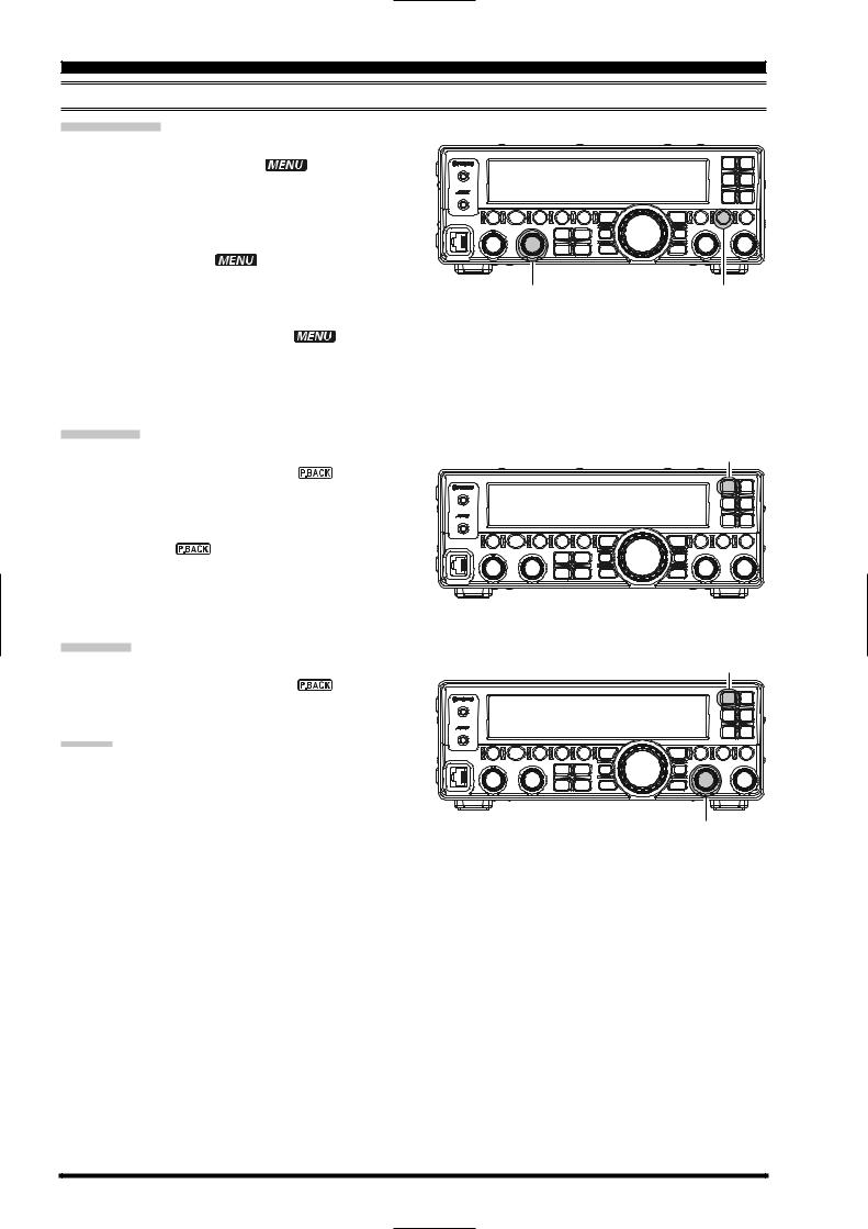
KEY DURATION SETTING
The duration that buttons are held determines the function they activate. Factory default is one second. Pressing a button for less than one second activates one function. Pressing and holding the button in for longer than one second activates another function.
The default one second release time can be changed to a shorter or longer duration, if desired.
To do this:
1.Press and hold the [F] button for one second to enter the Menu mode again. The “ ” icon will appear on the display.
2.Rotate the [DSP/SEL] knob to select menu item
“KEYHOLD”.
3.Press the [DSP/SEL] knob to enable adjustment of this menu item. The “ ” icon will be blinking.
4.Rotate the [DSP/SEL] knob to set the desired duration time. Available selections are 0.5/1.0/1.5/
2.0 sec. (default value: 1.0 sec).
You may Press the [RCL/HOME] button to reset the duration time to the factory default.
5.Press the [DSP/SEL] knob. The “ ” icon returns to appear continuously.
6.Press and hold the [F] button for one second to save the new setting and return to normal operation.
[RCL/HOME] button
[DSP/SEL] knob |
[F] button |
FT-450D OPERATION MANUAL |
Page 17 |
EASY OPERATION
RESETTING THE MICROPROCESSOR
The FT-450D has three reset methods.
VFO/MEMORY RESET
Use this procedure to reset (clear out) the Memory channels (Except the QMB channel) previously stored and VFO data, without affecting any configuration changes you may have made to the Menu settings.
1.Press and hold in the [POWER(ON/OFF)] button for one second to turn the transceiver off.
2.Press and hold the [(V/M)/MW] button. While holding it in, press and hold in the [POWER(ON/ OFF)] switch for one second to turn the transceiver on. Once the transceiver comes on, you may release the [(V/M)/MW] button.
MENU MODE RESET
Use this procedure to restore the Menu settings to their factory defaults, without affecting the memories you have programmed.
1.Press and hold in the [POWER(ON/OFF)] button for one second to turn the transceiver off.
2.Press and hold the [F] button. While holding it in, press and hold in the [POWER(ON/OFF)] button for one second to turn the transceiver on. Once the transceiver comes on, you may release the [F] button.
FULL RESET
Use this procedure to restore all Menu and Memory settings to their original factory defaults. All Memories will be cleared by this procedure.
1.Press and hold in the [POWER(ON/OFF)] button for one second to turn the transceiver off.
2.Press and hold the [RCL/HOME] button. While holding it in, press and hold in the [POWER(ON/
OFF)] button for one second to turn the transceiver on. Once the transceiver comes on, you may release the [RCL/HOME] button.
[ON/OFF] button |
[(V/M)/MW] button |
[ON/OFF] button |
[F] button |
[ON/OFF] button |
[RCL/HOME] button |
Page 18 |
FT-450D OPERATION MANUAL |
RECEIVING
TUNING STEPS
The tuning step of the [MAIN DIAL] knob and the
[DSP/SEL] knob is different depending on the operating mode.
OPERATING |
|
|
KNOB |
MODE |
|
[MAIN DIAL] |
[DSP/SEL] 1 |
LSB/USB |
|
1/10/20 Hz |
1.0/2.5/5.0 kHz |
CW |
|
1/10/20 Hz |
1.0/2.5/5.0 kHz |
AM |
|
100/200 Hz 2 |
2.5/5.0/9.0/10/12.5/25 kHz |
FM |
|
100/200 Hz 2 |
5.0/6.25/10/12.5/15/20/25/50 kHz |
DATA |
|
1/10/20 Hz |
1.0/2.5/5.0 kHz |
1: When you press the [DSP/SEL] knob, the tuning step of the [DSP/SEL] knob changes to 100 kHz in all modes.
2: In the factory default, the [MAIN DIAL] knob does not tune the AM and FM modes. However, you may activate the [MAIN DIAL] knob on the AM and FM mode via Menu Item “A&FDIAL”.
Pressing the [FAST] button will increase or decrease the tuning rate of the [MAIN DIAL] knob by a factor of ten and also increase or decrease the tuning rate of the [DSP/SEL] knob by a factor of two.
[FAST] button
[DSP/SEL] knob [MAIN DIAL] knob
NOTICE
Regarding of the [DSP/SEL] knob
The [DSP/SEL] knob is used for operating various functions depending on the situation.
If you can not change the frequency/memory channel by tuning the [DSP/SEL] knob, the [DSP/SEL] knob is selected to operate of one of the DSP functions.
In this case, press the [DSP] button several times until the “>” icon disappears from the DSP Graphic Display.
CHANGE THE TUNING STEP OF THE [MAIN DIAL] KNOB
1.Set the operating mode by pressing the
[MODE ]/[MODE ] button.
2.Press and hold the [F] button for one second to
enter the Menu mode. The |
” icon will ap- |
pear on the display. |
|
3.Rotate the [DSP/SEL] knob to select the menu item “DIALSTP”.
4.Press the [DSP/SEL] knob to enable adjustment
of this menu item. The |
” icon will be blink- |
ing. |
|
5.Rotate the [DSP/SEL] knob to select the desired tuning step described above.
(You may Press the [RCL/HOME] button to reset the tuning step to the factory default.)
6. Press the [DSP/SEL] knob. The ” icon is displayed continuously.
7.Press and hold the [F] button for one second to save the new setting and return to normal operation.
[DSP/SEL] button |
[RCL/HOME] button |
[MODE ]/[MODE ] button |
[F] button |
CHANGE THE TUNING STEP OF THE [DSP/SEL] KNOB
1.Set the operating mode by pressing the [MODE ]/[MODE ] button.
2.Press the [F] button momentarily.
3.Press the [SPLIT/STEP] button.
4.Rotate the [DSP/SEL] knob to select the desired tuning step described above.
5.Press the [DSP/SEL] knob to save the new setting and return to normal operation.
[DSP/SEL] knob |
[SPLIT/STEP] button |
[MODE ]/[MODE ] button |
[F] button |
FT-450D OPERATION MANUAL |
Page 19 |
RECEIVING
ABOUT THE [UP]/[DWN] BUTTONS OF THE MH-31A8J
The microphone [UP]/[DWN] keys utilize the tuning steps of the [MAIN DIAL] knob on the SSB/
CW/DATA mode, and utilize the tuning steps of the [DSP/SEL] knob on the AM/FM mode.
When the microphone [FST] key is pressed, the tuning rate increases by a factor of ten, in a manner similar to the effect of the transceiver frontpanel [FAST] button.
[FST] Key
[DWN] Key |
[UP] Key |
DWN FST |
UP |
DYNAMIC MICROPHONE
MH-31
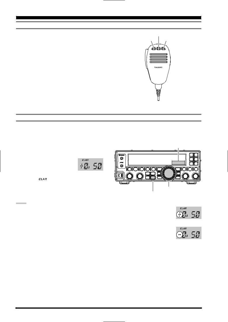
CLARIFIER
You may change the receiving frequency only without changing the transmit frequency.
1.Press the [CLAR] button to activate the clarifier. The “ ” icon will appear on the display.
2. Rotate the [MAIN DIAL] knob to tune the desired |
Clarifier Offset |
|
|
|
|
receive frequency. (Offset of up to ±9.99 kHz may |
|
|
be set using the clarifier.) |
|
|
The offset frequency will appear |
|
|
at the bottom right corner of the |
|
|
display. |
|
|
3. Press the [CLAR] button again to disable the clari- |
|
|
fier. The “ |
” icon will disappear from the dis- |
|
play. |
|
|
|
|
[MAIN DIAL] knob |
|
|
[CLAR] button |
NOTE:
Even when the clarifier is disabled, the variance of the clarifier remains (both TX and RX frequencies).
Press and hold in the [CLAR] button for one second to clear the clarifier offset, meaning the receiving frequency is equal to the transmit frequency.
When the [MAIN DIAL] knob is rotated to change the frequency after disabling the clarifier, the clarifier offset becomes “zero”, meaning the receiving frequency is equal to the transmit frequency.
When the receiving frequency is higher than transmit frequency, “+” will be appended to the offset frequency.
When the receiving frequency is lower than transmit frequency, “–” will be appended to the offset frequency.
You may assign the CLAR function to the [DSP/
SEL] knob via the Menu Item “CLAR”.
Page 20 |
FT-450D OPERATION MANUAL |
RECEIVING
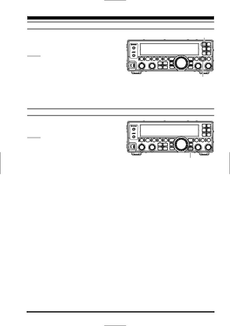
DIGITAL VOICE ANNOUNCEMENT
Press the [F] button followed by the [C.S/VOICE] button to announce the current operating frequency (with resolution to the displayed 100 Hz digit) and operating mode.
ADVICE:
If you assign the “VOICE2” function to the [C.S/VOICE] button via the menu item “PNL-C.S”, you may confirm the current operating frequency (with resolution to the displayed 100 Hz digit), operating mode, and S-meter reading through the voice message announcement system by pressing the [C.S/VOICE] button. See page
16 for details of the [C.S/VOICE] button assignment.
[C.S/VOICE] button
[F] button
DIAL LOCK
Pressing the [LOCK] button toggles the locking of the [MAIN DIAL] knob and some switches, to prevent accidental frequency changes.
ADVICE:
You may select the locking schemes via the menu item “LOCKMOD”. See page 83 for details.
[LOCK] button
FT-450D OPERATION MANUAL |
Page 21 |
RECEIVING
MY BANDS OPERATION
The “My Bands” feature allows you to select several Amateur bands, and make only those bands available for selection via the [BAND ]/[BAND ] buttons.
This feature can be very useful in a contest, where the 10/18/24 MHz band are not used, or if you do not have antennas for some bands.
MY BANDS SETUP
1. Press and hold the [F] button for one second to enter the Menu mode again. The ” icon will appear on the display.
2.Rotate the [DSP/SEL] knob to select the menu item “MY BAND”.
3.Press the [DSP/SEL] knob to enable adjustment of
this menu item. The |
” icon will be blinking. |
4.Press the [BAND ]/[BAND ] buttons to choose a band you wish to skip (omit) from the band selection loop.
5.Rotate the [DSP/SEL] knob to select “OFF”, and then press the [DSP/SEL] knob.
NOTE
The “OFF” selection sets the selected band to be
skipped, while the “ON” selection sets the selected band to be included in the band-selection list.
6. Press the [DSP/SEL] knob. The ” icon returns to appear continuously.
7.Repeat steps 4 through 6 to select/deselect as many bands as you like.
NOTE
The GEN (General Band) and the current band cannot be skipped.
8.Press and hold the [F] button for one second to save the new setting and return to normal operation.
[BAND ]/[BAND ] button |
|
[DSP/SEL] knob |
|
[F] button |
|
1.8MHz |
|
|
|
|
3.5MHz |
|
|
|
|
7MHz |
|
|
|
|
10MHz |
3.5MHz |
3.5MHz |
7MHz |
14MHz |
|
|
|
||
14MHz |
7MHz |
28MHz |
21MHz |
GEN |
|
|
|||
18MHz |
14MHz |
|
|
|
21MHz |
21MHz |
|
|
|
24MHz |
28MHz |
|
|
|
28MHz |
GEN |
|
|
|
50MHz |
|
|
|
|
GEN |
|
|
|
|
MY BANDS OPERATION
Press the [BAND ]/[BAND ] buttons to choose the
Amateur band on which you wish to operate. Only those Amateur bands that have not been skipped will appear as you scroll through the bands.
NOTE
If you want to recall an operating band which has been set to my band “OFF”, Press the [F] button, then press the [BAND ]/[BAND ] button until the desired band appears.
[BAND ]/[BAND ] button |
Page 22 |
FT-450D OPERATION MANUAL |
RECEIVING
MY MODES OPERATION
The “My Modes” feature allows you to select the operating modes you wish to have available for selection via the [MODE ]/[MODE ] buttons. Only the desired modes will be displayed in the loop.
This feature can be very useful in an HF operation, where the AM/FM/DATA modes are not used.
MY MODES SETUP
1. Press and hold the [F] button for one second to enter the Menu mode again. The ” icon will appear on the display.
2.Rotate the [DSP/SEL] knob to select the menu item “MY MODE”.
3.Press the [DSP/SEL] knob to enable adjustment of
this menu item. The |
” icon will be blinking. |
4.Press the [MODE ]/[MODE ] buttons to choose a mode you wish to skip (omit) from the mode selection loop.
5.Rotate the [DSP/SEL] knob to select “OFF”, and then press the [DSP/SEL] knob.
NOTE
The “OFF” selection sets the selected mode to be skipped, while the “ON” selection sets the selected
mode to be included in the mode-selection list. 6. Press the [DSP/SEL] knob. The ” icon
returns to appear continuously.
7.Repeat steps 4 through 6 to select/deselect as many modes as you like.
NOTE
The mode currently in use cannot be turned off.
8.Press and hold the [F] button for one second to save the new setting and return to normal operation.
[MODE ]/[MODE ] button |
[DSP/SEL] knob |
|
|
[F] button |
|
LSB |
|
|
|
|
USB |
|
|
|
|
LSB |
|
LSB |
USB |
FM |
CW |
|
|
|
|
USB |
|
|
|
|
AM |
|
|
|
|
FM |
|
|
MODE MODE |
|
FM |
|
|
|
|
KEYER CLAR
DATA
MY MODES OPERATION
Press the [MODE ]/[MODE ] buttons to choose the operating mode on which you wish to operate. Only those operating modes that have not been skipped will appear as you scroll through the modes.
NOTE
If you want to recall an operating Mode which has been set to my band “OFF”, Press the [F] button, then press the [MODE ]/[MODE ] button until the desired Mode appears.
[MODE ]/[MODE ] button |
FT-450D OPERATION MANUAL |
Page 23 |
RECEIVING
DIGITAL VOICE RECORDER
PREPARATIONS
1. Press and hold the [F] button for one second to enter the Menu mode. The ” icon will appear on the display.
2.Rotate the [DSP/SEL] knob to select the menu item “PNL-C.S”.
3.Press the [DSP/SEL] knob to enable adjustment of
|
this menu item. The |
” icon will be blinking. |
|
4. |
Rotate the [DSP/SEL] knob to select “P/B” to as- |
||
|
sign the Play Back feature to the [C.S/VOICE] |
||
|
button. |
|
|
5. |
Press the [DSP/SEL] knob. The |
” icon re- |
|
turns to appear continuously.
6.Press and hold the [F] button for one second to save the new setting and return to normal operation.
[DSP/SEL] knob |
[F] button |
RECORDING
1. Press and hold in the [C.S/VOICE] button for one second to initiate recording. The ” icon will appear in the display to confirm that recording is in progress. The recorder will store up to 20 seconds of the received audio and then halt the recording. The ” icon will go out.
2.You may halt the recording in progress, by pressing and holding the [C.S/VOICE] button for one second.
PLAYBACK
Press the [C.S/VOICE] button momentarily to begin playback of the recorded audio. The ” icon will blink in the display to confirm that playback is in progress.
ADVICE:
You may adjust the playback level of the recording with the [AF GAIN] knob
[C.S/VOICE] button
[C.S/VOICE] button
[AF GAIN] knob
Page 24 |
FT-450D OPERATION MANUAL |

CONVENIENCE FEATURES
RECEIVER OPERATION (FRONT END BLOCK DIAGRAM)
The FT-450D includes a wide range of special features to suppress the many types of interference that may be encountered on the HF bands. However, real world interference conditions are constantly changing, so optimum setting of the controls is somewhat of an art, requiring familiarity with the types of interference and the subtle effects of some of the controls. Therefore, the following information is provided as a general guideline for typical situations, and a starting point for your own experimentation.
The FT-450D’s interference-fighting circuitry begins in its “RF” stages, and continues throughout the entire receiver section. FT-450D allows configuration of the features described below.
R. FLT (IF Roofing Filters)
The Roofing filter, with a bandwidth of 10 kHz is provided in the 68 MHz First IF, right after the first mixer.
This filter provides narrow-band selectivity to protect the following IF and DSP stages, for special operating circumstances.
CONTOUR Filter (SEE PAGE 28)
The DSP Contour filter provides a unique capability on the receiver, providing either nulling or peaking of tunable segments of the receiver passband, so as to suppress interference or excessive frequency components on an incoming signal, or to peak those tunable frequency segments. The amount of nulling/ peaking, and the bandwidth over which it is applied, are adjustable via the Menu.
IF SHIFT (SEE PAGE 29)
The passband center frequency response of the IF
DSP filtering may be adjusted using this control.
IF WIDTH (SEE PAGE 30)
IF NOTCH (SEE PAGE 31)
The IF Notch filter is a high-Q notch filter that can significantly reduce, if not eliminate, an interfering carrier.
DNR (DIGITAL NOISE REDUCTION) (SEE PAGE 32)
The DSP’s Digital Noise Reduction (DNR) feature utilizes eleven different mathematical algorithms to analyze and suppress different noise profiles encountered on the HF/50 MHz bands. Choose the selection that provides the best noise suppression, which concurrently will allow the signal to rise up out of the noise.
AGC (SEE PAGE 27)
The AGC system is highly adaptable to changing signal and fading characteristics, making reception possible under the most difficult conditions.
The width of the IF DSP filtering may be adjusted using this control.
FT-450D OPERATION MANUAL |
Page 25 |
CONVENIENCE FEATURES
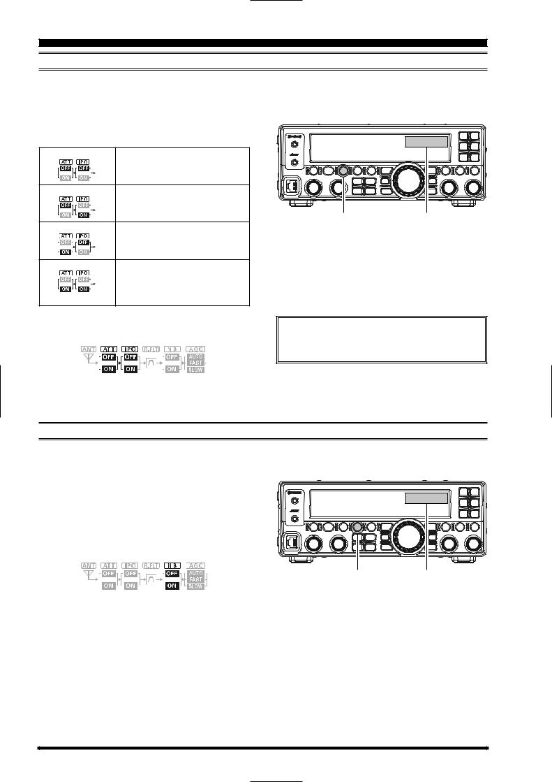
IPO/ATT (ADJUST THE RECEIVING SENSITIVITY)
You may reduce the receiving signal strength to 20 dB when extremely strong local signals or high noise degrade reception. You may optimize the characteristics of the receiver front-end, for best reception, depending on the noise levels and the signal strengths.
Press the [IPO/ATT] button several times to set the desired selection, per the chart below.
ATT: OFF, IPO: OFF |
Attenuator is OFF, and the incoming |
|
|
signal is amplified by the RF preampli- |
|
|
fier. |
|
ATT: OFF, IPO: ON |
Attenuator is OFF, and the incoming |
|
|
signal bypasses the RF preamplifier, |
|
|
yielding direct feed to the first mixer. |
|
|
[IPO/ATT] button |
Block Diagram |
ATT: ON, IPO: OFF |
Attenuator is ON, (the incoming signal |
|
|
is reduced by 20 dB) and the incom- |
|
|
ing signal is amplified by the RF pream- |
|
|
plifier. |
|
ATT: ON, IPO: ON |
Attenuator is ON, (the incoming signal |
|
|
power is reduced by 20 dB) and the |
|
|
incoming signal bypasses the RF |
|
|
preamplifier, yielding direct feed to the |
|
|
first mixer. |
|
The selection will be indicated in the Block Diagram on the display.
NOTE
An attenuator is always “ON” between 30kHz and 1.7MHz.
NOISE BLANKER (INTERFERENCE REJECTION “SIGNALS WITHIN 3 KHZ”)
The FT-450D includes an effective Noise Blanker, which can significantly reduce noise caused by automotive ignition systems.
1. Press the [NB] button to activate the Noise
Blanker.
2.Press the [NB] button again to disable the Noise Blanker.
The selection will be indicated in the Block Diagram on the display.
[NB] button |
Block Diagram |
Page 26 |
FT-450D OPERATION MANUAL |
CONVENIENCE FEATURES
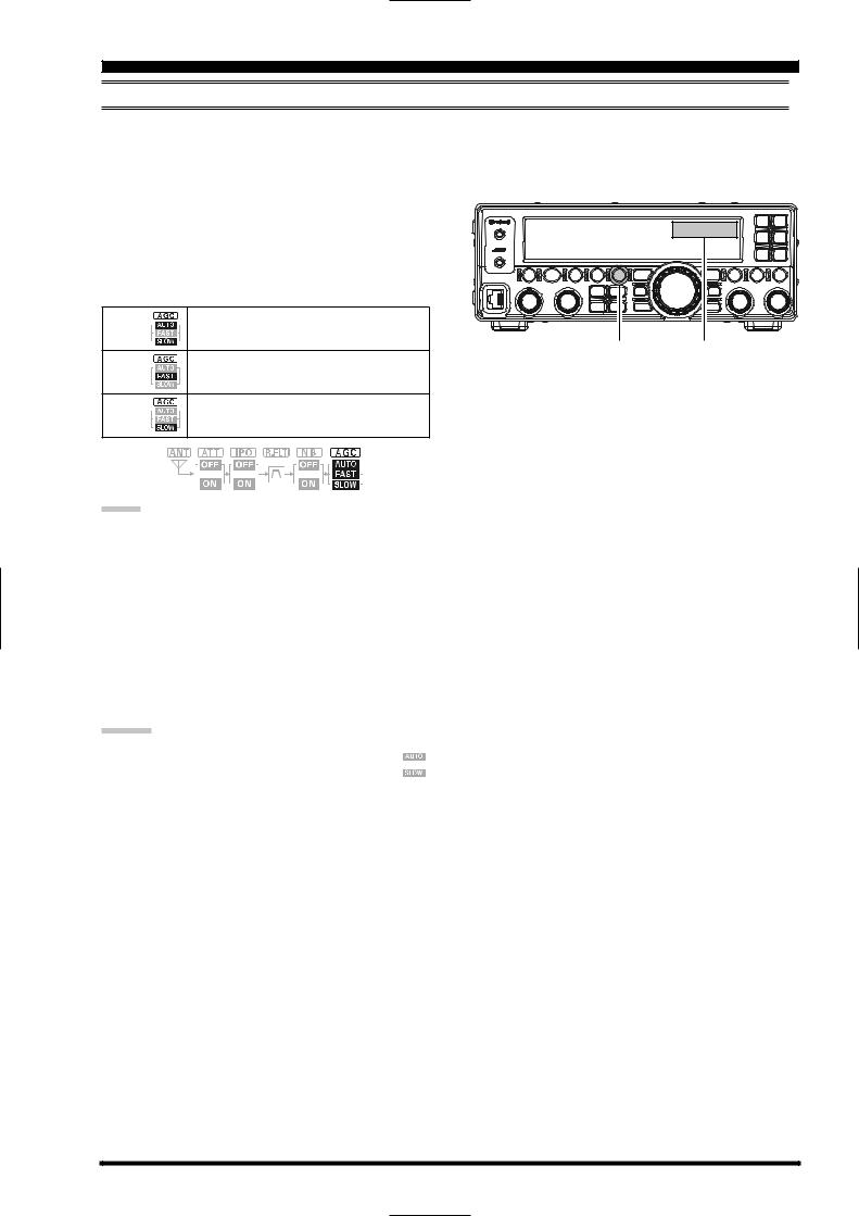
AGC (TOOL FOR COMFORTABLE AND EFFECTIVE RECEPTION)
The AGC system is designed to help compensate for fading and other propagation effects, with characteristics that can be of particular value on each operating mode. The basic objective of AGC is to maintain a constant audio output level once a certain minimum threshold of signal strength is achieved.
Press the [AGC] button repeatedly to select the desired receiver-recovery time constant. The AGC status is indicated in the Block Diagram displayed on the display. For most operations, we recommend the
“AUTO” mode. You may disable the AGC by pressing and holding in the [AGC] button for one second.
AUTO |
Sets the receiver-recovery time automatically |
|
depending on the operating mode. |
FAST |
[AGC] button Block Diagram |
Sets the receiver-recovery time to fast. |
|
|
This mode is suitable for CW/DATA recep- |
|
tion. |
SLOW |
Sets the receiver-recovery time to slow. |
|
This mode is suitable for SSB/AM reception. |
NOTE:
Normally, the “AUTO” selection is satisfactory for most situations, but in the event of operation on a crowded band where you wish to receive a weak signal, you may wish to change the setting (to FAST, for example). The “AUTO” mode selections are:
OPERATING MODE |
AUTO AGC SELECTION |
LSB |
SLOW |
USB |
SLOW |
CW |
FAST |
AM |
SLOW |
FM |
FAST (Fixed) |
DATA |
FAST |
ADVICE:
If the AGC receiver-recovery time is set to “Off”  by pressing and holding in the [AGC] button,
 the S-meter will no longer deflect. Additionally, you will likely encounter distortion on stronger signals, as the IF amplifiers and the following stages are probably being overloaded.
FT-450D OPERATION MANUAL |
Page 27 |

CONVENIENCE FEATURES
CONTOUR (INTERFERENCE REJECTION “SIGNALS WITHIN 3 KHZ”)
The Contour filtering system provides a gentle perturbation of the IF filter pass band, so as to suppress or enhance particular frequency components in five steps, thus improving the sound and/or readability of a received signal.
1.Press the [DSP] button several times to set the
“>” icon to the “CONTOUR” indicator of the DSP Graphic Display on the display.
2.Press the [DSP/SEL] knob to engage the contour filter.
3.Press and hold the [DSP/SEL] knob for one second to toggle the contour filter’s level between
“null” and “peak”.
4.Rotate the [DSP/SEL] knob to achieve the most natural-sounding audio reproduction on the incoming signal.
The peak position of the contour filter is graphi- cally-depicted in the “CONTOUR” indicator of the
DSP Graphic Display on the LCD.
5.Press the [DSP/SEL] knob again to increase the contour filter’s level (“null” or “peak”).
6.To disable the contour filter, press the [DSP/SEL] button again. The graphic disappears from the
“CONTOUR” indicator of the LCD Display, confirming that the contour filter is no longer operating.
CONTOUR “NULL”
CONTOUR “PEAK”
CONTOUR “OFF”
CONTOUR GAIN “LOW”
CONTOUR “NULL”
CONTOUR “PEAK”
CONTOUR “OFF”
CONTOUR GAIN “HIGH”
“CONTOUR” Indicator
[DSP/SEL] knob [DSP] button
Refer to Figure “B”, this shows a “indentation” of the contour filter is center of a passband. Counter-clockwise rotation (to the left) of the [DSP/SEL] knob causes the indentation to move toward a lower frequency within the passband, while clockwise rotation (to the right) causes the indentation to move toward a higher frequency within the passband. By removing interference or unwanted frequency components on the incoming signal, it is possible to make the desired signal rise out of the background noise/interference, enhancing intelligibility.
A |
B |
C |
IF |
IF |
IF |
BANDWIDTH |
BANDWIDTH |
BANDWIDTH |
QUICK POINT:
The steep slopes of the DSP filtering can, when adjusted aggressively, impart an unnatural sound to an incoming signal. Often, a narrow bandwidth is not the key to improving copy. The incoming signal itself may have undesirable or excessive frequency components. By judicious use of the Contour filter, the “shoulder” of the passband response may be altered, or components removed from within the passband, allowing the desired signal to rise above the background noise and interference in a manner not obtainable with other filtering systems.
Page 28 |
FT-450D OPERATION MANUAL |
 Loading...