


 Loading...
FT-818ND
Operating Manual
HF/VHF/UHF
SSB/CW/AM/FM ULTRA-COMPACT TRANSCEIVER

Contents
Introduction...................................................... |
1 |
Safety Precautions........................................... |
2 |
Accessories & Options.................................... |
4 |
Supplied Accessories...................................... |
4 |
Available Options............................................. |
4 |
Installation........................................................ |
5 |
Connecting the Supplied YHA-63 Antenna...... |
5 |
Connecting the Microphone............................. |
6 |
Shoulder Strap Installation.............................. |
6 |
Rubber Foot Installation.................................. |
6 |
Alkaline Battery Installation and Use............... |
7 |
External Power Connections........................... |
8 |
SBR-32MH Ni-MH Battery Pack |
|
Installation and Use......................................... |
9 |
Installation..................................................... |
9 |
Charging....................................................... |
9 |
Front Panel Control & Switches................... |
10 |
Display Icons............................................... |
13 |
Side Panel Switch & Connectors.................. |
14 |
Rear Panel Connectors.................................. |
15 |
Operation........................................................ |
16 |
Turning the Transceiver On and Off.............. |
16 |
Supply Voltage Display.................................. |
16 |
Operating Band Selection.............................. |
17 |
Mode Selection.............................................. |
17 |
Adjusting the Audio Volume Level................. |
17 |
Menu Quick Start........................................... |
18 |
Adjusting the RF Gain and Squelch.............. |
18 |
Setting the Operating Frequency................... |
19 |
Stacked VFO System.................................... |
19 |
Operation on 5 MHz Band (U.S. Version Only).... |
20 |
Receiver Accessories.................................... |
21 |
Clarifier (Receiver Incremental Tuning)......... |
21 |
IF SHIFT........................................................ |
22 |
AGC (Automatic Gain Control)...................... |
22 |
Noise Blanker................................................ |
23 |
IPO (Intercept Point Optimization)................. |
23 |
ATT (Front End Attenuator)............................ |
23 |
AM/FM DIAL.................................................. |
24 |
Automatic Power-Off Feature........................ |
24 |
Transmitter Operation.................................... |
25 |
SSB Transmission......................................... |
25 |
Basic Setup/Operation................................ |
25 |
VOX Operation............................................ |
26 |
CW Transmission.......................................... |
27 |
Operation using Straight Key/ |
|
External Keying Device............................... |
27 |
Operation using Built-in Electronic Keyer... |
29 |
FM Transmission........................................... |
30 |
Basic Setup/Operation................................ |
30 |
Repeater Operation.................................... |
30 |
DCS Operation............................................ |
32 |
ARTSTM (Auto Range Transpond System) |
|
Operation.................................................... |
33 |
CW Identifier Setup..................................... |
33 |
Digital Mode Operation (SSB-Based AFSK).... |
34 |
RTTY (Radio TeleType) Operation.............. |
34 |
PSK31 Operation........................................ |
35 |
“USER” Defined Digital Modes................... |
36 |
Packet (1200/9600 bps FM) Operation......... |
37 |
AM Transmission........................................... |
38 |
Split Frequency Operation............................. |
38 |
Time-Out Timer.............................................. |
39 |
Weather Fax Monitoring................................ |
39 |
Memory Operation......................................... |
40 |
QMB Channel................................................ |
40 |
QMB Channel Storage................................ |
40 |
QMB Channel Recall.................................. |
40 |
Memory Operation on “Regular” |
|
Memory Channels......................................... |
41 |
Normal Memory Storage............................. |
41 |
Split-Frequency Memory Storage............... |
41 |
Memory Channel Recall.............................. |
42 |
Masking Memory......................................... |
42 |
Memory Operation on “HOME” Channel |
|
Memories....................................................... |
43 |
HOME Channel Storage............................. |
43 |
HOME Channel Recall................................ |
43 |
Labeling Memories........................................ |
44 |
Setting the Spectrum Scope Mode............. |
45 |
Activate the Spectrum Scope...................... |
45 |
Spectrum Scope Monitor Operation............. |
45 |
Smart Search™ Operation............................ |
46 |
Scanning Operation....................................... |
47 |
Scanning Operation....................................... |
47 |
Scan Skip Programming (Memory Mode Only)... |
48 |
Programmable Memory Scan (PMS) Operation... |
49 |
Dual Watch Operation.................................... |
50 |
Operation on Alaska Emergency |
|
Frequency: 5167.5 khz (U.S. Version Only)... |
51 |
Menu Operation.............................................. |
52 |
Cloning............................................................ |
63 |
CAT System Programming............................ |
64 |
CAT Data Protocol......................................... |
65 |
Constructing and Sending CAT Commands... |
65 |
Opcode Command Chart............................ |
66 |
Installation of Optional Accessories............ |
68 |
Optional Filters YF-122S/YF-122C/YF-122CN.... |
68 |
Power-on Microprocessor Reset Procedure.... |
69 |
Appendix......................................................... |
69 |
BAND DATA FORMAT................................... |
69 |
Specifications................................................. |
70 |

Introduction
The FT-818 is a compact, innovative multiband, multimode portable transceiver for the amateur radio MF/HF/VHF/UHF bands. Providing coverage of the 160-10 meter bands plus the 6 m, 2 m, and 70 cm bands, the FT-818 includes operation on the SSB, CW, AM, FM, and Digital modes, yielding the most comprehensive performance package available for portable operation.
Designed for use with either an external DC power source or internal batteries. The FT-818 provides 6 watts of power output from a 13.8-Volt external power supply. When using the SBR-32MH Ni-MH battery pack or Alkaline Battery Holder, the FT-818 will automatically reduce the output power (2.5 Watts or more).
The multi-function Liquid-Crystal Display includes Blue, Amber, and Violet backlighting, which may be disabled for battery conservation. The display includes bar-graph indication of power output, ALC voltage, SWR, and modulation level. Also include are a number of operating status icons, as well as the function displays for the three operating function keys ( ,
,  , and
, and  ).
).
Among the advanced features of the FT-818 are many incorporated only in large base-sta- tion transceivers. These include Dual VFOs; Split-Frequency operation; IF Shift; Clarifier (“R.I.T.”); IF Noise Blanker; AGC Fast/Slow/Auto/Off selection; RF Gain and Squelch control; IPO (Intercept Point Optimization) and a receiver front-end Attenuator; AM Aircraft reception; AM and FM Broadcast reception; VOX; Built-in Electronic Keyer; Adjustable CW Pitch; Automatic FM Repeater Shift (ARS); Built-in CTCSS Encoder/Decoders; ARTS™ (Auto-Range Transponder System); Smart Search™ Automatic Memory Loading System; Spectrum Scope; 200 Memories plus Home Channels and Band-limiting Memories; Al- pha-Numeric Labeling of Memories;Automatic Power-Off (APO) and Time-Out Timer (TOT) functions; Computer Interface capability; and Cloning capability.
We urge you to read this manual in its entirety, so as to gain a full understanding of the amazing capability of the exciting FT-818 Portable Transceiver.
1

Safety Precautions
Note beforehand that the company shall not be liable for any damages suffered by the customer or third parties in using this product, or for any failures and faults that occur during the use or misuse of this product, unless otherwise provided for under the law.
Type and meaning of the marks
DANGER |
This mark indicates an imminently hazardous situation, which, if not avoided, could |
|
result in death or serious injury. |
|
|
WARNING |
This mark indicates a potentially hazardous situation, which, if not avoided, could |
|
result in death or serious injury. |
|
|
CAUTION |
This mark indicates a potentially hazardous situation, which, if not avoided, may |
|
result in minor or moderate injury or only property damage. |
|
|
Type and meaning of symbols |
|
|
Prohibited actions that must not be attempted, in order to use this radio safely. |
|
|
For example, signifies that disassembly is prohibited. |
|
|
Precautions that must be adhered to in order to use this radio safely. For example, |
signifies that the |
|
power supply is to be disconnected. |
|
|
 DANGER
Do not use the device in “regions or aircrafts and vehicles where its use is prohibited” such as in hospitals and airplanes.
This may exert an impact on electronic and medical devices.
Do not use this product while driving or riding a motorbike. This may result in accidents.
Make sure to stop the car in a safe location first before use if the device is going to be used by the driver.
Do not operate the device when flammable gas is generated.
Doing so may result in fire and explosion.
Never touch the antenna during transmission.
This may result in injury, electric shock and equipment failure.
Do not transmit in crowded places in consideration of people who are fitted with medical devices such as heart pacemakers.
Electromagnetic waves from the device may affect the medical device, resulting in accidents caused by malfunctions.
When an alarm goes off with the external antenna connected, cut off the power supply to this radio immediately and disconnect the external antenna from this radio.
If not, this may result in fire, electric shock and equipment failure.
Do not touch any liquid leaking from the liquid display with your bare hands.
There is a risk of chemical burns occurring when the liquid comes into contact with the skin or gets into the eyes. In this case, seek medical treatment immediately.
 WARNING
Do not use voltages other than the specified power supply voltage.
Doing so may result in fire and electric shock.
Do not transmit continuously for long periods of time.
This may cause the temperature of the main body to rise and result in burns and failures due to overheating.
Do not dismantle or modify the device.
This may result in injury, electric shock and equipment failure.
Do not handle the power plug and connector etc. with wet hands. Also do not plug and unplug the power plug with wet hands.
This may result in injury, liquid leak, electric shock and equipment failure.
Keep the power plug pins and the surrounding areas clean at all times.
This may result in fire, liquid leak, overheating, breakage, ignition etc.
When smoke or strange odors are emitted from the radio, turn off the power and disconnect the power cord from the socket.
This may result in fire, liquid leak, overheating, damage, ignition and equipment failure. Please contact our company amateur customer support or the retail store where you purchased the device.
Disconnect the power cord and connection cables before incorporating items sold separately and replacing the fuse.
This may result in fire, electric shock and equipment failure.
Never cut off the fuse holder of the DC power cord.
This may cause short-circuiting and result in ignition and fire.
Do not use fuses other than those specified.
Doing so may result in fire and equipment failure.
Do not allow metallic objects such as wires and water to get inside the product.
This may result in fire, electric shock and equipment failure.
2
Safety Precautions
Do not place the device in areas that may get wet easily (e.g. near a humidifier).
This may result in fire, electric shock and equipment failure.
When connecting a DC power cord, pay due care not to mix up the positive and negative polarities.
This may result in fire, electric shock and equipment failure.
Do not use DC power cords other than the one enclosed or specified.
This may result in fire, electric shock and equipment failure.
Do not bend, twist, pull, heat and modify the power cord and connection cables in an unreasonable manner.
This may cut or damage the cables and result in fire, electric shock and equipment failure.
Refrain from using headphones and earphones at a loud volume.
Continuous exposure to loud volumes may result in hearing impairment.
Do not pull the cable when plugging and unplugging the power cord and connection cables.
Please hold the plug or connector when unplugging. If not, this may result in fire, electric shock and equipment failure.
Do not use the device when the power cord and connection cables are damaged, and when the DC power connector cannot be plugged in tightly.
Please contact our company amateur customer support or the retail store where you purchased the device as this may result in fire, electric shock and equipment failure.
Follow the instructions given when installing items sold separately and replacing the fuse.
This may result in fire, electric shock and equipment failure.
Do not use the device when the alarm goes off.
For safety reasons, please pull the power plug of the DC power equipment connected to the product out of the AC socket.
Never touch the antenna as well. This may result in fire, electric shock and equipment failure due to thunder.
 CAUTION
Do not place this device near a heating instrument or in a location exposed to direct sunlight.
This may result in deformation and discoloration.
Do not place this device in a location where there is a lot of dust and humidity.
Doing so may result in fire and equipment failure.
Stay as far away from the antenna as possible during transmission.
Long-term exposure to electromagnetic radiation may have a negative effect on the human body.
Do not wipe the case using thinner and benzene etc.
Please use a soft and dry piece of cloth to wipe away the stains on the case.
Keep out of the reach of small children.
If not, this may result in injuries to children.
Do not put heavy objects on top of the power cord and connection cables.
This may damage the power cord and connection cables, resulting in fire and electric shock.
Do not transmit near the television and radio.
This may result in electromagnetic interference.
Do not use optional products other than those specified by our company.
If not, this may result in equipment failure.
When using the device in a hybrid car or fu- el-saving car, make sure to check with the car manufacturer before using.
The device may not be able to receive transmissions normally due to the influence of noises from the electrical devices (inverters etc.) fitted in the car.
Do not turn on the volume too high when using a headphone or earphone.
This may result in hearing impairment.
For safety reasons, switch off the power and pull out the DC power cord connected to the DC power connector when the device is not going to be used for a long period of time.
If not, this may result in fire and overheating.
Do not throw or subject the device to strong impact forces.
This may result in equipment failure.
Do not the put this device near magnetic cards and video tapes.
The data in the cash card and video tape etc. may be erased.
Do not place the device on an unsteady or sloping surface, or in a location where there is a lot of vibration.
The device may fall over or drop, resulting in fire, injury and equipment failure.
Do not stand on top of the product, and do not place heavy objects on top or insert objects inside it.
If not, this may result in equipment failure.
Do not use a microphone other than those specified when connecting a microphone to the device.
If not, this may result in equipment failure.
Do not touch the heat radiating parts.
When used for a long period of time, the temperature of the heat radiating parts will get higher, resulting in burns when touched.
Do not open the case of the product except when replacing the fuse and when installing items sold separately.
This may result in injury, electric shock and equipment failure.
3

Accessories & Options
|
|
|
Supplied Accessories |
MH-31A8J |
Hand Microphone |
SBR-32MH |
Ni-MH Battery Pack (9.6 V, 1900 mAh) |
SAD-24B/C |
Battery Charger |
FBA-28 |
Battery Holder (holds 8 “AA” size Alkaline cells [not supplied]) |
YHA-63 |
Whip Antenna for (50/144/430 MHz) |
DC Cable |
|
Alkaline Battery Holder |
|
Shoulder Strap |
|
Ferrite Core |
|
Rubber Foot |
|
|
|
|
Available Options |
SBR-32MH |
Ni-MH Battery Pack (9.6 V, 1900 mAh) |
SAD-24B/C |
Battery Charger |
YF-122S |
Collins SSB Filter (2.3 kHz/4.7 kHz: –6 dB/–66 dB) |
YF-122CN |
Collins CW Filter (300 Hz/1 kHz: –6 dB/–60 dB) |
MH-31A8J |
Hand Microphone |
MH-36E8J |
DTMF Microphone |
M-1 |
Reference Microphone |
M-100 |
Dual Element Microphone |
YH-77STA |
Lightweight Stereo Headphone |
SCU-17 |
USB Interface Unit |
CSC-83 |
Soft Case |
CT-62 |
CAT Interface Cable |
CT-39A |
Packet Cable |
ATAS-25 |
Active Tuning Antenna (Manual Type) |
: Depends on the transceiver version.
4
Installation
Connecting the Supplied YHA-63 Antenna
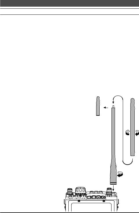
Your FT-818 is supplied with a three-section antenna, model YHA-63 which is designed for optimum performance on the 50 MHz, 144 MHz, and 430 MHz. It also works well on the FM broadcast and other VHF bands. This antenna is intended for connection to the front panel’s BNC-type antenna connector.
For HF and/or 50 MHz operation, most hikers carry their own dipole or collapsible vertical antenna, fed by a small-diameter coaxial cable terminated in a type “M” (PL-259) plug, and these kinds of antennas may be connected to the rear panel’s antenna connector.
The YHA-63 should be connected to the top panel’s “BNC” connector, using the following guidelines:
For 144/430 MHz operation (only), connect the shorter cap section to the screw post on the top of the main antenna shaft, then screw the assembled YHA-63 onto the BNC connector, twisting it 1/4 turn clockwise to secure the antenna.
For 50 MHz operation, unscrew the short cap section, and replace it with the long cap section. The long cap section will provide good results on 144/430 MHz, as well, but those owners not using 50 MHz may prefer the shorter total length of the YHA-63
when using the short cap on 144/430 MHz. For shortwave listening using a ran-
dom-length wire antenna for reception only, you may wish to consider connection of the wire between the main YHA-63 shaft and the cap, using a “spade lug” or similar lug on the end of the wire to provide a secure connection between the cap and the rest of the antenna.
Menu #07 (“ANTENNA”) allows you to define which connector (“Front” or
“Rear”) is used on a particular band. See page 54 for details.
C |
B |
A |
UP |
DWN |
|
BAND |
|
MODE |
5
Installation
Connecting the Microphone
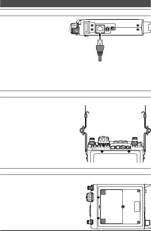
To connect the microphone, plug
its connector (latch side UP) into the MIC jack on the right side of the transceiver. Press it gently inward until you hear the “click” of the latch.
To disconnect the microphone, press gently on the “PUSH ” label on top
of the microphone connector’s rubber boot. While pressing on this spot,
gently pull the connector outward from the body of the transceiver.
Note: During “Digital” or “Packet” operation, it is not necessary to disconnect the microphone, as activation of the PTT line from the DATA connector automatically cuts off the audio input from the MIC jack.
Shoulder Strap Installation
The convenient Shoulder Strap is designed for maximum comfort and security for your FT818 transceiver.
Refer to the illustration, and connect the shoulder strap to the attachment tabs just behind the front panel of the FT-818. Be sure to have the shoulder strap aligned correctly, without twists in the straps.
A convenient microphone hanger is located on one end of the padded top section of the Shoulder Strap. When not in use, the microphone may be affixed here, freeing both of your hands for other tasks.
C |
B |
A |
UP |
DWN |
|
BAND |
|
MODE |
Rubber Foot Installation
Four Rubber Feet are provided with your FT-818, for ease of use when operating from a
base station or camp table. |
|
|
|
Refer to the illustration, and affix the Rubber Feet |
|
|
|
in the appropriate locations. |
|
||
|
|||
|
|
||
|
|
|
6
Installation
Alkaline Battery Installation and Use
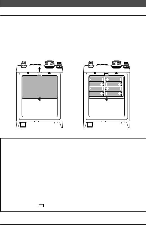
The FT-818 is supplied with the FBA-28 holder for Alkaline “AA” cells. A fresh set of Alkaline cells should provide approximately 5.5 hours of reception under typical conditions.
1.To install or replace the AA cells, first remove the battery cover from the bottom side of the transceiver. Slide the battery cover latch forward, as shown in the illustration, then fold the battery cover upward and set it aside temporarily.
2.Install the Alkaline AA cells as shown in the illustration, paying particular attention to the correct polarity of the batteries.
3.When all batteries have been successfully installed, replace the battery cover.
Important Notes
When the transceiver is to be stored for a long period of time without use (longer than ten days), remove the batteries from the FBA-28 holder, to avoid the possibility of battery leaking causing damage to the transceiver. Inspect the FBA28 battery holder occasionally for signs of corrosion or battery leakage, and remove the batteries immediately if any such damage is observed.
The FBA-28 battery holder is designed for use solely with Alkaline type “AA” cells. Do not attempt to use Ni-MH or other rechargeable cells in the FBA-28, because it does not contain the protection circuitry required when using rechargeable cells.
When replacing batteries, replace all eight AA cells simultaneously with fresh batteries.
When the battery voltage is approaching the value which indicates depletion is near, the small “ ” will blink, indicating it is time to replace the batteries.
7
Installation
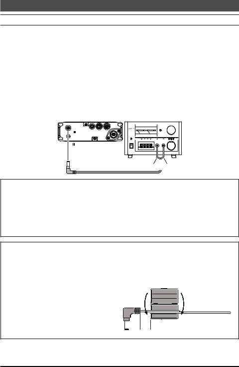
External Power Connections
The FT-818 may be connected to an external 13.8 Volt DC power source providing at least 3 Amps of continuous-duty current.. The supplied DC cable may be used for DC connections.
While connected to an external DC source, if you have installed the supplied SBR-32MH Ni-MH Battery Pack, the DC cable connection to the external DC power source will allow operation of the FT-818 while charging of the SBR-32MH is in progress.
When making DC power connections, be absolutely certain to follow the markings on the DC cable so as to ensure proper polarity of the connection to the power supply. Connect the Red and Black or White and Black wire to the Positive (+) power supply terminal, and connect the Solid Black wire to the Negative (-) power supply terminal.
FT-818
INPUT DC13.8V:
GND
<![if ! IE]><![endif]>INPUT DC13.8V
|
|
ANT |
KEY |
DATA |
ACC |
|
|
|
|
|
|
|
|
|
FP-1030A |
|
0 |
5 |
10 |
15 |
20 |
0 |
5 |
20 |
30 |
40 |
|
POWER SUPPLY |
|
|
|
|
|
|
|
|
|
|
FP-1030A |
|
V |
|
|
|
|
A |
|
OVERLOAD |
|
|
CONTINUOUS |
CURRENT |
25A |
|
|
|
||||
|
|
|
|
|
6A |
|
|
|
25A |
10A |
POWER |
|
|
|
|
|
|
|
|
|
|
ON |
|
|
|
|
|
|
|
|
|
|
OFF |
|
|
|
|
|
|
|
|
|
|
|
RED/BLACK |
|
|
|
or |
|
BLACK |
Supplied DC Cable |
WHITE/BLACK |
|
|
Notice
Be extremely careful when making power supply connections. Use only a 13.8 Volt DC Supply, and carefully observe the proper electrical polarity. Serious damage may result if these precautions are not observed.
The Limited Warranty on this product does not cover damage caused by improper power supply connections, or improper power supply voltage.
Important Note
Occasionally, the 430 MHz transmit signal may behave abnormally when the FT818 is operated using an External Power Supply and the whip antenna, especially with the antenna in close proximity to surrounding metal objects.
If abnormal transmitter operation is experienced, wind one turn of the DC cable around the supplied ferrite core, and snap its two halves together, per the illustration below. Install the core as close as possible to the DC plug, as shown.
wind one turn, snap two halves
DC Cable

 as close as possible
8
Installation
SBR-32MH Ni-MH Battery Pack Installation and Use
The supplied SBR-32MH Ni-MH Battery Pack provides 9.6 Volts of DC power for your FT818, with a maximum capacity of 1900 mAh.
Installation
1. To install the SBR-32MH Ni-MH Battery
Pack, first remove the battery compart- 


 ment cover, as described previously.
2. Lift out the FBA-28 battery holder, and disconnect the short cable connected to
the FBA-28, as shown in the illustration.
3. Connect the short cable to the mating connector on the SBR-32MH, and install the SBR-32MH in the battery compart-
ment.
4. Replace the battery compartment cover.
SBR-32MH
FBA-28
Charging
Charging of the SBR-32MH requires the use of either the supplied battery charger (SAD24B/C), or an external 13.8 Volt (±15%) DC source. If the battery charger is used, the FT818 must be turned off during charging; if an external 13.8 Volt DC source is used (connected via the supplied DC cable), then you may operate the FT-818 while charging is in progress.
1.Turn the FT-818 off, then connect the supplied battery charger DC connector to the INPUT: 13.8V  jack on the rear panel of the FT-818.
2.Plug the battery charger into the nearest AC wall outlet.
3.Press the FT-818’s  switch for one second to turn the transceiver on.
4.Press the  key momentarily.
5.Rotate the  knob so that the function row containing “[CHG, VLT, DSP]” appears on the display.
6.Press the  key to select the [CHG] option (the display will immediately revert to the regular frequency display).
7.Turn the FT-818 off. The display will indicate “CHG TIME RMN”
and remaining time to indicate the time remaining before a full charge is achieved on the SBR-32MH.
Important Note
The SAD-24B/C are not designed to power the transceiver for operation (reception or transmission).
Please be advised that the SAD-24B/C may contribute noise to TV and radio reception in the immediate vicinity, so we do not recommend its use adjacent to such devices.
9
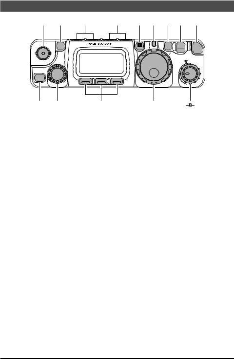
Front Panel Control & Switches
F |
HOME |
|
|
V M |
LOCK |
PWR |
|
|
|
|
||
SEL |
|
|
|
F |
SQL/RF |
|
|
|
|
||
|
|
|
|
A |
|
CLAR |
|
|
|
|
|
A |
B |
C |
|
|
|
|
|
|
|
|
|
 PWR Switch
Press and hold in the  switch for one second to turn to the transceiver on or off.
 AF Knob
The (inner)  knob adjusts the receiver audio volume level presented to the internal or external speaker. Clockwise rotation increases the volume level.
 SQL/RF Knob
In the USA version, this (outer)  knob adjusts the gain of the receiver’s RF and IF stages. Using Menu Selection 45, this control may be changed to function as a Squelch control, which may be used to silence background noise when no signal is present. In the other versions, its default setting is set to “Squelch”.
 LOCK Key
Pressing this key locks the front panel keys so as to prevent accidental frequency change.
 V/M Key
Pressing this key switches frequency control between the VFO and Memory Systems.
 TRANSMIT/BUSY Indicator
This LED glows green when the squelch opens, and turns red during transmit.
 MAIN Dial
This is the main tuning dial for the transceiver. It is used both for frequency tuning as well as “Menu” setting in the transceiver.
 F Key
F Key
Pressing this key momentarily changes the display to show the operating functions available via the  ,
,  ,
,  keys.
keys.
Press and hold this key for one second to activate the “Menu” mode.
10

Front Panel Control & Switches
 FUNC Keys
These three keys select many of the most important operating features of the transceiver. When pressing the  key, the current function of that key appears above each of the
  ,
,  ,
,  keys (along the bottom of the LCD); rotating the
  knob scrolls the display through eleven rows of functions available for use via the
  ,
,  ,
,  keys.
keys.
The available features are shown in chart on the next page.
 BAND(DWN)/BAND(UP) Key
Pressing either of these keys momentarily will cause the frequency to be moved up or down by one frequency band. The selections available are:
1.8 MHz
 3.5 MHz
 5.0 MHz
 7.0 MHz
 10 MHz
 14 MHz
 15 MHz
 18 MHz
430 MHz
 144 MHz
 108 MHz
 88 MHz
 50 MHz
 28 MHz
 24 MHz
 21 MHz
 MODE()/MODE() Key
Pressing either of these keys momentarily will change the operating mode. The selections available are:
 LSB
LSB 
 USB
USB 
 CW
CW 
 CWR
CWR 
 AM
AM
 FM
FM
 DIG
DIG
 PKT
PKT 
 HOME Key
Pressing this key momentarily recalls a favorite “Home” frequency memory.
 SEL Knob
This detented rotary switch is used for tuning, memory selection, and function selection for the  ,
,  ,
,  keys of the transceiver.
 CLAR Key
Press this key momentarily to activate the Receiver Clarifier feature. When this feature is activated, the  knob may be used to set a tuning offset of up to ±9.99 kHz. The transmitter’s frequency is not affected by the setting of the Clarifier.
Press and hold this key for 1/2 second to activate the IF Shift feature, which allows you to use the  knob to adjust the center frequency of the IF filter’s passband response.
 ANT Jack
Connect the supplied 50/144/430 MHz rubber flex antenna (or another antenna presenting a 50Ω impedance) to this BNC connector.
In its default setting, this jack does not function on the HF bands. If you want to enable this jack on the HF bands, recall and change the setting of Menu #07.
11
Front Panel Control & Switches
|
|
key |
|
key |
|
key |
|
Press the |
A/B |
|
A=B |
|
SPL |
|
key to switch |
Press and hold in the |
Press the |
key to activate |
||
1 |
between VFO-A and VFO-B |
key for 1/2 second to copy the |
Split frequency operation be- |
|||
on the display. |
contents of VFO-A into the |
tween VFO-A and VFO-B. |
||||
|
|
|
VFO-B register, so that the |
|
|
|
|
|
|
two VFOs’ contents will be |
|
|
|
|
|
|
identical. |
|
|
|
|
|
MW |
|
MC |
|
TAG |
|
Press and hold in the |
Press the |
key to des- |
Press the |
key to select |
|
2key for 1/2 second to transfer ignate the current Memory the display type (Frequency the contents of the VFO into a channel to be “skipped” or Alpha-numeric Tag) during
|
Memory register. |
during scanning. |
Memory operation. |
||||
|
Press the |
STO |
|
RCL |
|
PMS |
|
3 |
key to store |
Press the |
key to recall |
Press the |
key to activate |
||
the contents of the VFO into |
the QMB Memory. |
the Programmable Memory |
|||||
|
the QMB (Quick Memory |
|
|
Scan feature. |
|||
|
Bank) register. |
|
|
|
|
||
|
Press the |
RPT |
|
REV |
|
TON |
|
|
key to select |
Press the |
key to reverse |
Press the |
key to activate |
||
|
the direction of the uplink |
the transmit and receive |
CTCSS or DCS operation. |
||||
|
frequency shift (“–,” “+,” or |
frequencies while working |
Press and hold in the |
||||
4 |
Simplex) during FM repeater |
through a repeater. |
key for 1/2 second to recall |
||||
operation. |
|
|
|
Menu #48 (for selecting the |
|||
|
|
|
|
||||
|
Press and hold in the |
|
|
CTCSS tone frequency). |
|||
|
key for 1/2 second to recall |
|
|
|
|
||
|
Menu #42 (for setting the shift |
|
|
|
|
||
|
frequency offset). |
|
|
|
|
||
|
Press the |
SCN |
|
PRI |
|
DW |
|
5 |
key to initiate |
Press the |
key to activate |
Press the |
key to activate |
||
scanning (in the direction of |
the Priority Scan feature. |
the Dual Watch system. |
|||||
|
|||||||
|
higher frequencies). |
|
|
|
|
||
|
Press the |
SSM |
|
SCH |
|
ART |
|
|
key to activate |
Press the |
key to activate |
Press the |
key to initiate |
||
|
the Spectrum Scope Monitor |
Smart SearchTM operation. |
the Auto-Range Transponder |
||||
6 |
feature. |
|
|
|
mode. |
|
|
Press and hold in the |
|
|
Press and hold in the |
||||
|
|
|
|||||
|
key for 1/2 second to recall |
|
|
key for 1/2 second to recall |
|||
|
Menu #43 (for selecting the |
|
|
Menu #09 (for selecting the |
|||
|
SSM sweep mode). |
|
|
ARTS “Beep” option). |
|||
|
Press the |
IPO |
|
ATT |
|
NAR |
|
|
key to bypass |
Press the |
key to engage |
Press the |
key to activate |
||
|
the receiver preamplifier, |
the receiver front-end atten- |
the “Narrow” filter mode in the |
||||
|
thereby activating Intercept |
uator, which will reduce all |
CW (optional YF-122C or YF- |
||||
|
Point Optimization for im- |
signals and noise by approxi- |
122CN required) mode. On |
||||
7 |
proved overload characteris- |
mately 10 dB. |
the FM mode, it also selects |
||||
tics. |
|
The ATT feature does not |
the low-deviation mode re- |
||||
|
The IPO feature does not |
function on 144/430 MHz. |
quired for HF FM operation |
||||
|
function on 144/430 MHz. |
|
|
on 29 MHz. |
|
||
|
|
|
Press and hold in the |
||||
|
|
|
|
|
|||
|
|
|
|
|
key for 1/2 second to recall |
||
|
|
|
|
|
Menu #38 (to Enable/Disable |
||
|
|
|
|
|
the optional filter during instal- |
||
|
|
|
|
|
lation). |
|
|
12
Front Panel Control & Switches
|
|
key |
|
key |
key |
|
Press the |
NB |
|
AGC |
– |
8 |
key to activate |
Press the |
key to select |
No function |
|
the receiver’s IF Noise Blank- |
the recovery time (Fast, |
|
|||
|
er. |
|
Slow, Auto, or Off) for the |
|
|
|
|
|
receiver’s AGC system. |
|
|
|
Press the |
PWR |
|
MTR |
– |
|
key to select |
Press the |
key to select |
No function |
|
9the transmitter power output the display function of the level (Low 1, Low 2, Low 3, meter in the transmit mode
|
or High). |
|
(Power, ALC, SWR, or MOD |
|
|
|
|
|
|
indication). |
|
|
|
|
Press the |
VOX |
|
BK |
|
KYR |
|
key to enable |
Press the |
key to activate |
Press the |
key to activate |
|
|
the VOX (voice-operated |
CW “Semi” |
Break-in opera- |
the built-in Electronic Keyer. |
||
10 |
transmitter switching system) |
tion. |
|
Press and hold in the |
||
in the SSB, AM, and FM |
Press and hold in the |
key for 1/2 second to recall |
||||
|
modes. |
|
key for 1/2 second to recall |
Menu #21 (for setting the |
||
|
Press and hold in the |
Menu #17 (for setting the CW |
Keyer speed). |
|||
|
key for 1/2 second to recall |
Delay time). At a setting of 10 |
|
|
||
|
Menu #51 (for setting the |
ms, operation emulates full |
|
|
||
|
VOX Gain level). |
QSK performance. |
|
|
||
|
Press the |
CHG |
|
VLT |
|
DSP |
|
key to initiate |
Press the |
key to display |
Press the |
key to switch |
|
11 |
Battery Charging. |
the current battery voltage. |
the display between the Large |
|||
Press and hold in the |
|
|
Character and Small Charac- |
|||
|
key for 1/2 second to recall |
|
|
ter modes. |
|
|
|
Menu #11 (for selecting the |
|
|
|
|
|
|
Charging period). |
|
|
|
|
|
12 |
Press the |
TCH |
|
DCH |
|
– |
key to initiate |
Press the |
key to initiate |
No function |
|||
|
Tone Search. |
DCS Search. |
|
|
||
* The Operating Function number in this column does not appear on the LCD.
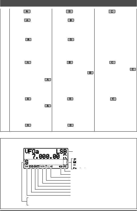
Display Icons
Operating Mode |


 Rear Panel Antenna Selected (page 54)


 LOCK Feature Active (page 10)
S: S-Meter
PO: TX Power Meter
AL: ACL Meter


 FST
FST Button (MH-31A8J) Active
Low Battery!
Split Frequency Operation Active (page 38) Low TX Power Selected (page 25) Automatic Power-Off Active (page 24) Digital Coded Squelch Active (page 32)
CTCSS Decoder Active (page 31)
CTCSS Encoder Active (page 31)
Repeater Shift Direction (page 30)
Dual Watch Active (page 50)
SW: SWR Meter MO: Deviation Meter
: This operation does not function in the FM Broadcast frequencies.
13
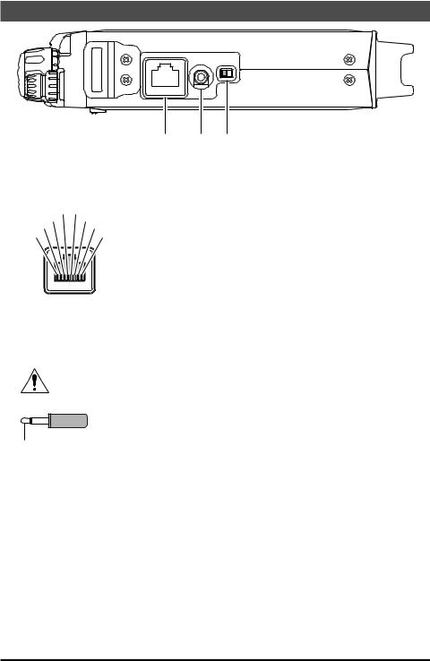
Side Panel Switch & Connectors
SP/PH SP- PH
MIC |
|
|
|
 MIC Jack
Connect the supplied MH-31A8J Hand Microphone to this jack.
|
MIC |
MIC GND |
|
PTT |
+5 V |
||
GND |
|
UP |
|
FAST |
|
DOWN |
|
|
|
|
|
MIC
 SP/PH Jack
This 3.5-mm, 2-pin jack provides variable audio output for an external speaker (4 Ω - 16 Ω impedance) or earphones. The audio level varies according to the setting of the front panel’s  knob.
knob.
When you insert an earphone plug into this jack, the SP-PH slide switch (located to the right side of this jack) MUST BE set to the “PH” position, to prevent the
possibility of injury to your ears.
 GND
GND
SIGNAL
 SP-PH Switch
If you use earphones with this transceiver, move this switch to the “PH” position before inserting the earphone plug into the SP/PH Jack, to prevent injury your ears.
14
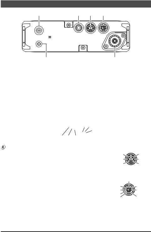
Rear Panel Connectors
|
|
|
|
|
ANT |
: |
KEY |
DATA |
ACC |
INPUT DC13.8V |
|
|
|
GND |
|
|
|
|
|
|
|
 INPUT:13.8V
  Jack (

 )
)
This is the DC power supply connection for the transceiver, used when operating the transceiver with an external power supply. Use the supplied DC cable to connect this jack to the car battery or base station DC power supply, which must be capable of supplying at least 3A @ 8 - 16 VDC. This jack is also used for battery charging (when using the supplied SBR-32MH battery pack).
 GND Terminal
For best performance and safety, this Ground lug may be connected to a good earth ground using a short, heavy, braided cable.
 KEY Jack
This 3.5-mm, 3-pin jack |
DOT DASH |
|
KEY GND |
|
is used for connection to |
COMMON |
|
|
|
a CW keyer paddle or a |
DOT DASH COMMON |
KEY NC GND |
|
|
|
|
|
||
straight key. |
When connecting an electronic keyer paddle |
When connecting a single straight key |
||
DATA Jack |
||||
|
|
|
||
This 6-pin, mini-DIN jack accepts AFSK input from a Termi- |
SQL |
DATA OUT |
||
nal Node Controller (TNC); it also provides fixed-level Re- |
|
1200bps |
||
DATA OUT |
PTT |
|||
ceiver Audio Output, Push-To-Talk (PTT), Squelch Status, |
9600bps |
|||
|
||||
GND |
DATA IN |
|||
and ground lines. |
|
|||
|
|
|
||
 ACC Jack
This 8-pin, mini-DIN jack provides a closure to ground during transmission, ALC, a transmitter-inhibit pin, and
“band data” for connection to an external amplifier. It is also used for Transceiver-to Transceiver Cloning and for control of this transceiver using a personal computer.
|
ALC |
TX INH |
BAND DATA |
RX D |
GND |
TX D |
+13.8V |
TX GND |
 ANT Jack
Connect your HF and/or 50 MHz antenna’s 50-ohm coaxial cable to this M-type (“SO239”) connector. In its default setting, this jack does not function on 50/144/430 MHz bands. If you want to enable this jack on 50/144/430 MHz bands, recall and change the settings of Menu #07.
15

Operation
Turning the Transceiver On and Off
1. |
To turn the transceiver on, press and hold in the |
|
|
|
|
switch for one second. |
|
2. |
To turn the transceiver off, again press and hold |
|
|
|
in the |
switch for one second. |
CLAR |
The one-second delay helps you avoid accidental switching on (or off) of DC power.
HOME |
SEL
A 
 B
B 
 C
C
PWR
F |
|
|
V M |
LOCK |
PWR |
|
||
|
F |
SQL/RF |
|
|
|
|
A |
|
Supply Voltage Display
When you turn on the transceiver, the DC supply voltage is indicated in the upper left corner of the LCD for two seconds. After this interval, the display will resume its normal indication of the operating mode (VFOa, VFOb, or Memory Channel Number).
To view the supply voltage at any time during operation:
1.Press the  key momentarily, then rotate the
  knob to select Operating Function Row 11* [CHG, VLT, DSP] on the display.
2.Press the  (VLT) key momentarily to display the supply voltage in the upper right corner of the LCD.
3.To cancel the supply voltage display, again press the  (VLT) key.
Remember, the Operating Row Number does not appear on the display.
If you have not operated your FT-818 within the past week, we recommend that you plug in the Battery Charger, and perform a 10 hour (use for SAD-24B/C) charge cycle, to ensure that the SBR-32MH is ready for operation when you are.
16
Operating Band Selection |
|
Operation |
|||
|
|
|
|
||
This transceiver covers an incredibly wide fre- |
|
|
BAND( DWN) |
|
|
quency range, over which a number of different |
|
|
BAND( UP) |
|
|
|
|
|
|
|
|
operating modes are used. Therefore, this trans- |
|
|
F |
|
|
ceiver’s frequency coverage has been divided into |
HOME |
|
V M |
A |
|
E |
|
|
|
||
|
|
|
|
LOCK |
PWR |
|
S L |
|
|
F |
SQL/RF |
different operating bands, each of with has its own |
CLAR |
|
|
|
|
preset channel steps and operating modes. You |
A |
B |
C |
|
|
|
|
|
|
|
|
can change the channel steps and operating mode once you get started, of course, per |
|||||
the next section. |
|
|
|
|
|
To change the frequency band, press either the  or
or  key to move to the next lower or higher operating band, respectively.
1.8 MHz
 3.5 MHz
 5.0 MHz
 7.0 MHz
 10 MHz
 14 MHz
 15 MHz
 18 MHz
430 MHz
 144 MHz
 108 MHz
 88 MHz
 50 MHz
 28 MHz
 24 MHz
 21 MHz
1)Recalling the 5 MHz band (U.S. model) requires different procedure. See page 20 for details.
2)VFOa and VFOb are independent VFOs, so they may be set to different bands. See the “Stacked VFO System” discussion on page 19 for details.
Mode Selection
Press either the  or
or  key to move among the eight settings for the operating modes, respectively.
 LSB
LSB 
 USB
USB 
 CW
CW 
 CWR
CWR 
CLAR
 AM
AM
 FM
FM
 DIG
DIG 
 PKT
PKT 
HOME |
SEL
MODE()
MODE()
F |
|
|
V M |
LOCK |
PWR |
|
||
|
F |
SQL/RF |
|
|
|
|
A |
|
A 
 B
B 
 C
C
You can also set VFOa and VFOb to different modes in the same band, allowing you to have a “Phone” VFO and a “CW” VFO, for example.
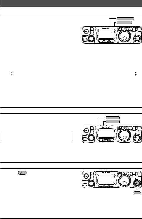
Adjusting the Audio Volume Level
Rotate the |
knob to set a comfortable listen- |
ing level. |
|
When operating in the “DIG” or “PKT” modes, you 
 CLAR
CLAR 
 may set the
  knob to any comfortable setting,
  or even all the way off, because the output from
the DATA jack is a fixed-level audio signal.
|
|
F |
|
|
HOME |
V M |
LOCK |
PWR |
|
|
|
|
||
S |
L |
|
F |
SQL/RF |
E |
|
|
A |
|
A 
 B
B 
 C
C
AF
Start with the  knob set fully counter-clockwise, especially when using FM (the background noise on FM can be surprisingly loud)!
17
Operation
Menu Quick Start
Many aspects of this transceiver’s configuration may be customized using the convenient “Menu” system, which allow you to configure many “set and forget” settings just the way you want to. A full discussion of the Menu system beings on page 52; for now, here is a brief discussion on how to change Menu settings:
1.Press and hold in the  key for one second to enter the Menu mode.
2.Rotate the  knob to recall the Menu item to be changed (for example, Menu #01, which Enables or Disables the Automatic Repeater Shift on the 144 MHz band).
3.Rotate the  knob to set this feature (in this example, the default setting is “ENABLE,” so rotate the
  knob to set this feature to “DISABLE”.
4.Press and hold in the  key for one second to save the new setting and exit to normal operation.
If you have momentarily pressed the key to change an operating function, press the
  key momentarily again (to clear the function indications for the
  ,
,  ,
,  keys) before engaging the Menu.
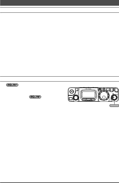
Adjusting the RF Gain and Squelch
The |
control is configured differently, depending on the country to which the FT- |
||
818 has been exported. In the U.S. version, the |
|
F |
|
default function of this control is “RF Gain”. The |
SEL |
|
|
|
|
HOME |
V M |
configuration of the |
control is set via |
|
AF |
|
CLAR |
|
|||
A B |
C |
|||
Menu #45; see page 61 for details. |
||||
|
|
|||
If your transceiver is configured for “RF Gain” use,
rotating this control fully clockwise in the SSB/CW/Digital modes will provide best sensitivity. To reduce the receiver’s RF Gain somewhat, rotate this control counter-clockwise slightly. You will observe an increasing number of bars on the S-meter as you rotate the  control counter-clockwise; this indicates increasing AGC voltage, which is causing the front-end gain to be reduced. In the FM and Packet modes, this control will automatically be set to an “Auto-Squelch” mode, wherein the FM/Packet squelch threshold is preset at the factory; the
  control still acts as an “RF Gain” control, however, and it normally should be set fully clockwise.
If this control is configured for “SQL” operation, the FT-818’s RF Gain will be set for maximum sensitivity in all modes, and the  control will function solely as a Squelch control. In this case, rotate the
  control to the point where the background noise is just silenced; this will provide the best sensitivity to weak signals, while keeping the receiver quiet when no signal is received. The LED just above the Main Dial will glow Green when the squelch is opened by an incoming signal or noise.
Note: Squelch operation does not function in the FM Broadcast frequencies.
Battery consumption is significantly reduced if the receiver is squelched, as the audio amplifier stage is shut off when the receiver is muted.
18
Operation
Setting the Operating Frequency
1. |
In the “SSB/CW/DIG” modes, rotate the |
|
F |
|
|
|||
|
knob to set the frequency. Clockwise rotation |
HOME |
V M |
LOCK |
PWR |
|||
|
|
|
||||||
|
S L |
|
F |
SQL/RF |
||||
|
of the |
knob increases the operating fre- |
E |
|
A |
|
||
|
CLAR |
|
|
|
||||
|
quency. |
|
|
A B |
C |
|
|
|
|
|
|
|
|
|
|
||
2. |
In the “AM/FM/PKT” modes, rotate the |
SEL |
DIAL |
|
|
|||
|
knob to set the frequency. Clockwise rotation of |
|
|
|||||
|
|
|
|
|
||||
|
the |
knob increases the operating frequency. |
|
|
|
|
||
3. |
You may also use the |
|
knob to adjust the operating frequency in the “SSB/CW/ |
|||||
|
DIG” modes. The |
knob provides faster tuning, ideal for making quick changes |
||||||
|
in frequency when you want to move across the band in a hurry. You can then use the |
|||||||
|
|
knob to make fine frequency adjustments. |
|
|
|
|
||
4. |
If you press the |
knob momentarily, then rotate the |
knob, you can now |
|||||
|
change the operating frequency in 1 MHz steps, allowing very quick frequency excur- |
|||||||
|
sions. This can be particularly helpful on the VHF and UHF bands. |
|
|
|
||||
5. |
In step 2 above, it was mentioned that tuning in the “AM/FM/PKT” modes is accom- |
|||||||
|
plished using the |
knob. By default, the |
knob is disabled in these modes; if |
|||||
|
you wish to enable the |
|
knob in these modes, use Menu #04; see page 54. |
|
|
|||
6. |
The synthesizer steps for the |
knob may be adjusted independently by mode. Use |
||||||
|
Menu #06 for AM, #30 for FM, and #47 for SSB/CW/Digital. See pages 54, 58, and |
|||||||
|
61 for details. |
|
|
|
|
|
|
|
The main  knob synthesizer’s tuning rate (the number of steps per rotation of the
  knob) can be adjusted using Menu #33. See page 59 for details.
Stacked VFO System
1. Press the  key momentarily, then rotate the
  knob, as needed, until Operating Function Row 1 [A/B, A=B, SPL] appears on the display.
2. Now press the  (A/B) key to toggle between the “A” and “B” VFOs. There are two such VFOs provided on each Amateur band, so you may set VFO-A to the CW subband, and VFO-B to the SSB sub-band, if you like. The operating mode will be preserved, along with the frequency information, on each VFO.
19
Operation
Operation on 5 MHz Band (U.S. Version Only)
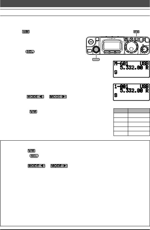
The FT-818 includes the capability for transmission and reception on the five spot frequencies assigned to the Amateur Service in the United States. To operate on the 5 MHz band:
1. Press the |
key once to enter the “Memory” |
|
|
|
|
|
|
mode (a memory channel number “M-nnn” will |
|
|
F |
|
|
||
appear on the display in the space previously |
|
|
|
|
|||
HOME |
|
|
V M |
LOCK PWR |
|||
occupied by “VFOa” or “VFOb”). |
|
CLAR |
|
|
|
SQL/RF |
|
|
|
|
SEL |
|
|
|
AF |
|
|
|
|
|
|
|
|
2. Rotate the |
knob to select the desired |
A |
B |
C |
|
|
|
channel (“M-601” through “M-605”), at the facto- |
SEL |
|
|
|
|
||
ry, with the permitted frequencies in the 5 MHz |
|
|
|
|
|||
|
|
|
|
|
|||
band. |
|
|
|
|
|
|
|
If you have partitioned your memory channels into Memory |
|
|
|
|
|||
Groups via Menu #34, the memory channel numbers for |
|
Memory Group “OFF” |
|||||
60-meter operation will be displayed as “l - 001” ~ “l-005”. See |
|
||||||
page 42 for details regarding Memory Group operation, and |
|
|
|
|
|||
page 59 for details regarding Menu #34. |
|
|
|
|
|
||
3. Pressing the |
or |
key momentarily, switch- |
|
|
|
|
|
es the operating mode between SSB and CW. |
|
|
Memory Group “ON” |
||||
4. To exit from 60-meter operatin and return to the VFO mode, |
|
||||||
|
CH No. |
Frequency |
|||||
just press the |
key (the memory channel number will be |
|
|||||
replaced by “VFOa” or “VFOb”). |
|
|
|
M-601 |
5.3320 MHz |
||
The frequencies and operating mode for 5 MHz band opera- |
|
M-602 |
5.3480 MHz |
||||
|
M-603 |
5.3585 MHz |
|||||
tion are both fixed, and may not be changed. |
|
|
|||||
|
|
M-604 |
5.3730 MHz |
||||
|
|
|
|
|
M-605 |
5.4050 MHz |
|
|
|
PSK Operation on 5 MHz Band |
|
1. |
Press the |
key once, if necessary, to enter the “Memory” mode. |
|
2. |
Rotate the |
knob to select the desired channel (“M-601” through “M-605”), |
|
|
at the factory, with the permitted frequencies in the 5 MHz band. |
||
3. |
Press the |
or |
key to select the SSB mode. |
4.When the “transmit” command is received from the TNC, the FT-818 transmitter will be engaged. The microphone input is disabled automatically when transmitting the PSK signal.
Likewise, the TNC “receive” command will cause the radio to revert to the receive mode.
You can adjust DATA input level using Menu #25 [DIG MIC].
During PSK operation via the rear panel DATA jack, the front panel MIC jack is cut off, so you won’t have a “live microphone” problem during data operation.
Set the PSK sub carrier frequency of the TNC to 1.5 kHz.
20
Receiver Accessories
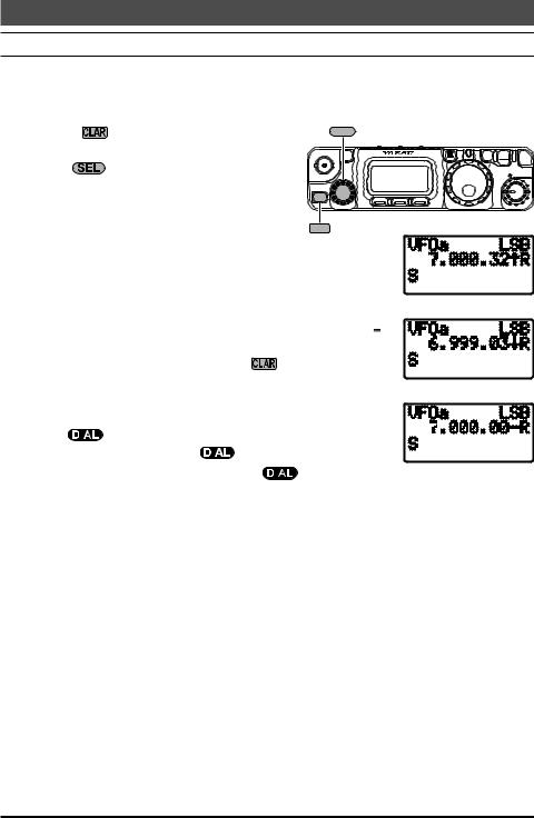
Clarifier (Receiver Incremental Tuning)
The Clarifier allows you to set an offset of up to ±9.99 kHz of the receive frequency relative to your transmit frequency. To achieve a wider offset than this, you may use the “Split” operating mode, described later.
1. |
Press the |
switch momentarily to activate |
SEL |
|
|
|
|
|
2. |
the Clarifier function. |
|
|
|
F |
|
|
|
Turn the |
knob, which allows the receiver |
S |
L |
|
V M |
F |
SQL/RF |
|
|
|
|
HOME |
|
LOCK |
PWR |
||
|
|
|
|
|
|
|
||
|
frequency to be varied over a range of 9.99 |
E |
|
|
|
A |
|
|
|
CLAR |
|
|
|
|
|
||
|
kHz. |
|
|
A |
B |
C |
|
|
3.When the receiving frequency is higher than CLAR transmit frequency, the “  ” icon will appear at
the right of the frequency display. Similarly, when the receiving frequency is lower than transmit frequency, the “ ” icon will
|
appear at the right of the frequency display. |
|
|
|
|
|
|
|
|
|
|
[TX < RX] |
||||||
4. |
When the receiving frequency is equal to transmit frequency |
|
|
|
||||||||||||||
|
(Clarifier offset is zero) while the Clarifier is activated, the “ ” |
|
|
|
|
|
|
|
|
|||||||||
|
icon will appear at the right of the frequency display. |
|
|
|
|
|
|
|||||||||||
5. |
To turn the Clarifier off, again press the |
|
switch momentar- |
|
|
|
|
|
|
|
|
|
|
|
||||
|
|
|
|
|
|
|
|
|
|
|
|
|||||||
|
ily. When you turn the Clarifier back on, the offset previously |
|
|
|
[TX > RX] |
|||||||||||||
|
stored will still be applied. |
|
|
|
|
|
|
|
|
|
|
|
|
|||||
|
|
|
|
|
|
|
|
|
|
|
|
|
|
|
|
|||
6. |
To reset the Clarifier offset to zero, turn the Clarifier off, then |
|
|
|
|
|
|
|
||||||||||
|
turn the |
|
knob by any amount. The Clarifier will reset to |
|
|
|
|
|
|
|
|
|
||||||
|
|
|
|
|
|
|
|
|
|
|
||||||||
|
zero after the first “step” of the |
|
knob. |
|
|
|
|
|
|
|
|
|
|
[TX = RX] |
||||
If you leave the Clarifier on, moving the |
|
knob will not |
|
|
|
|||||||||||||
|
||||||||||||||||||
|
||||||||||||||||||
cause the offset to be cancelled. |
|
|
|
|
|
|
|
|
|
|
|
|
|
|
|
|||
21
Loading...