


7MWTW1955EW1
Whirlpool 7MWTW1955EW1, 7MWTW1500EM1, 7MWTW1700EM1, 7MWTW1805EM1, 7MWTW1950EW1 Installation Guide
...
WASHER INSTALLATION INSTRUCTIONS
INSTRUCCIONES DE INSTALACIÓN DE LA LAVADORA
Table of Contents Índice
WASHER SAFETY ..............................................................1
INSTALLATION REQUIREMENTS .....................................2
Tools and Parts ..................................................................... 2
Location Requirements .......................................................2
Drain System ........................................................................ 3
Electrical Requirements ......................................................4
INSTALLATION INSTRUCTIONS .......................................4
Before you start: remove shipping materials ....................4
Connect Drain Hose ............................................................. 5
Connect Inlet Hoses ............................................................. 6
Level Washer ........................................................................7
Complete Installation Checklist .......................................... 8
INSTALLATION NOTES
Date of purchase: _________________________________
Date of installation: _______________________________
Installer: ________________________________________
Model number: ___________________________________
Serial number: ___________________________________
SEGURIDAD DE LA LAVADORA .................................9
REQUISITOS DE INSTALACIÓN .................................9
Herramientas y piezas ...................................................9
Requisitos de ubicación ...............................................10
Sistema de desagüe ......................................................11
Requisitos eléctricos ....................................................11
INSTRUCCIONES DE INSTALACIÓN ........................12
Antes de comenzar: quite los materiales
de transporte .................................................................12
Conexión de la manguera de desagüe ........................ 13
Conexión de las mangueras de entrada .....................14
Nivelación de la lavadora .............................................15
Complete la instalación ...........................Contraportado
NOTAS SOBRE LA INSTALACIÓN
Fecha de compra: ________________________________
Fecha de instalación: ______________________________
Instalador: ______________________________________
Número de modelo: _______________________________
Número de serie: _________________________________
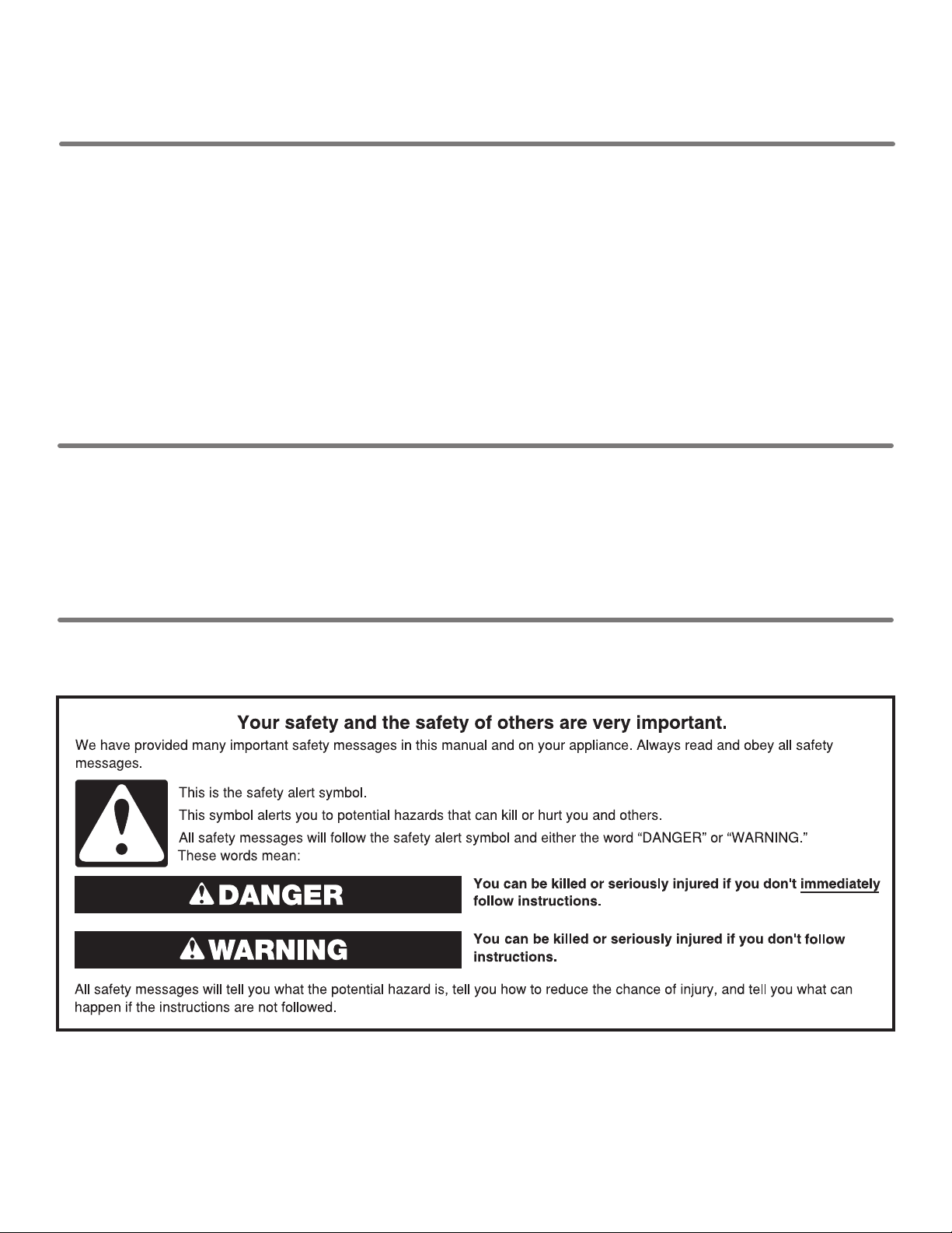
WASHER SAFETY
W10807862A
271/2"
INSTALLATION REQUIREMENTS
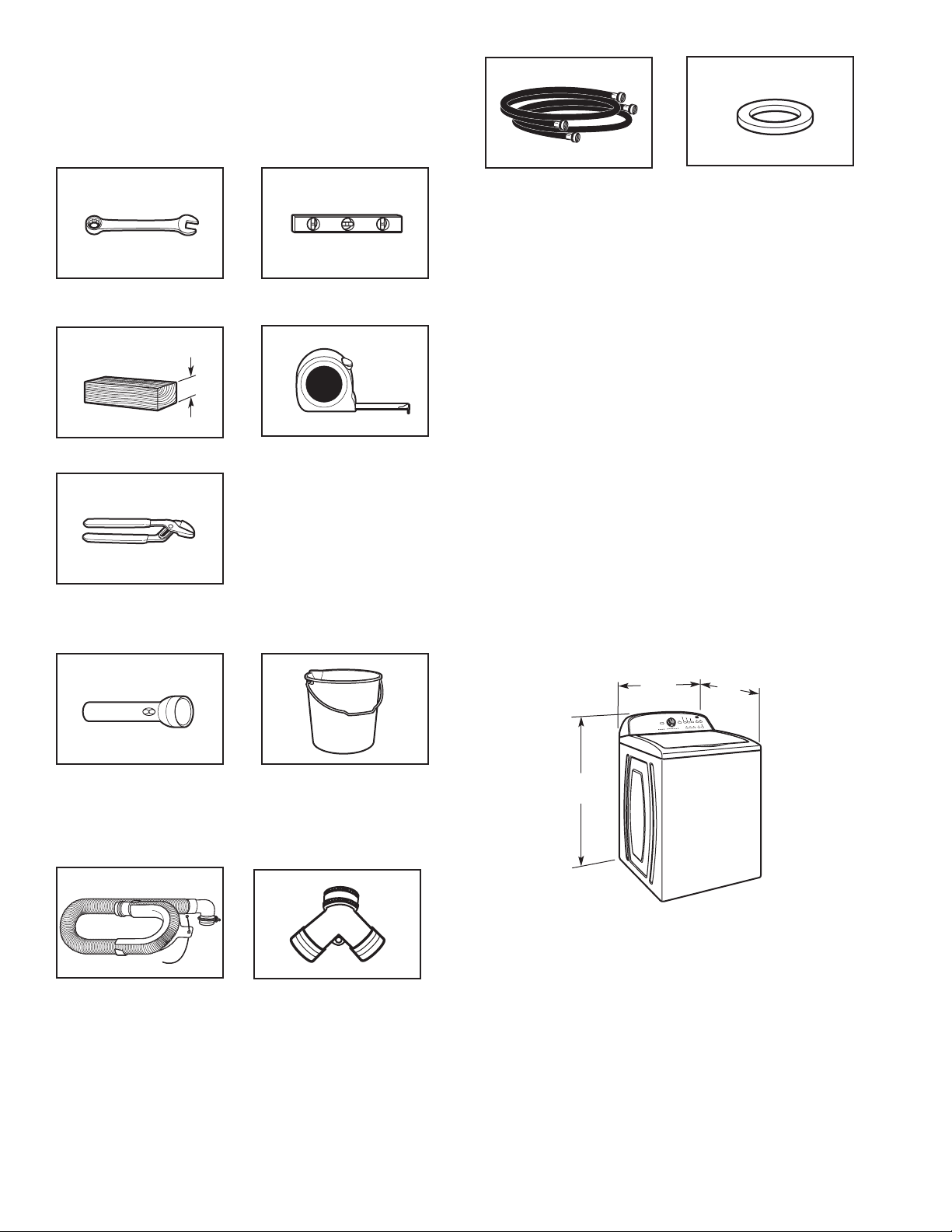
Tools and Parts
Gather required tools and parts before starting installation.
Tools needed:
Adjustable or open end
wrench
Wood block
9
⁄
” (14 mm)
16
4" min
(102 mm)
Level
Ruler or measuring tape
Inlet hoses with
flat washers
Rubber washer
Alternate parts: (Not supplied with washer)
Your installation may require additional parts.
If you have: You will need:
Overhead sewer Standard 20 gal. (76 L) 39" (990 mm)
tall drain tub or utility sink, sump
pump and connectors (available from
local plumbing suppliers)
1" (25 mm) standpipe 2" (51 mm) diameter to 1" (25 mm)
diameter Standpipe Adapter
Part Number 3363920
Connector Kit Part Number 285835
Drain hose too short Extension Drain Hose Part
Number 285863
Connector Kit Part Number 285835
Lint clogged drain Drain Protector Part Number 367031
Connector Kit Part Number 285835
Pliers that open to
13⁄4" (44.5 mm)
Optional tools:
Flashlight Bucket
Parts supplied:
NOTE: All parts supplied for installation are in
cardboard insert in the top of the washer.
Drain hose with clamp,
U-form, and cable tie
“Y” connector
LOCATION REQUIREMENTS
Select proper location for your washer to improve performance
and minimize noise and possible “washer walk”. Install your
washer in a basement, laundry room, closet, or recessed area.
(699 mm)
42"
(1067 mm)
27"
(686 mm)
2
You will need:
3"
4.5"
(114 mm)
n
A water heater set to 120° F (49° C).
n
A grounded electrical outlet located within 4 ft (1.2 m) of
power cord on back of washer.
n
Hot and cold water faucets located within 3 ft (0.9 m) of hot
and cold water fill valves on washer and water pressure
of 20-100 psi (138-690 kPa).
n
A level floor with maximum slope of 1" (25 mm) under entire
washer. Installing on carpet is not recommended.
n
Floor must support washer’s total weight (with water and load)
of 315 lbs (143 kgs).
IMPORTANT: Do not install, store, or operate washer where it will
be exposed to weather or in temperatures below 32° F (0° C).
Water remaining in washer after use may cause damage in low
temperatures. See “Washer Care” in your Use and Care Guide
for winterizing information.
Proper installation is your responsibility.
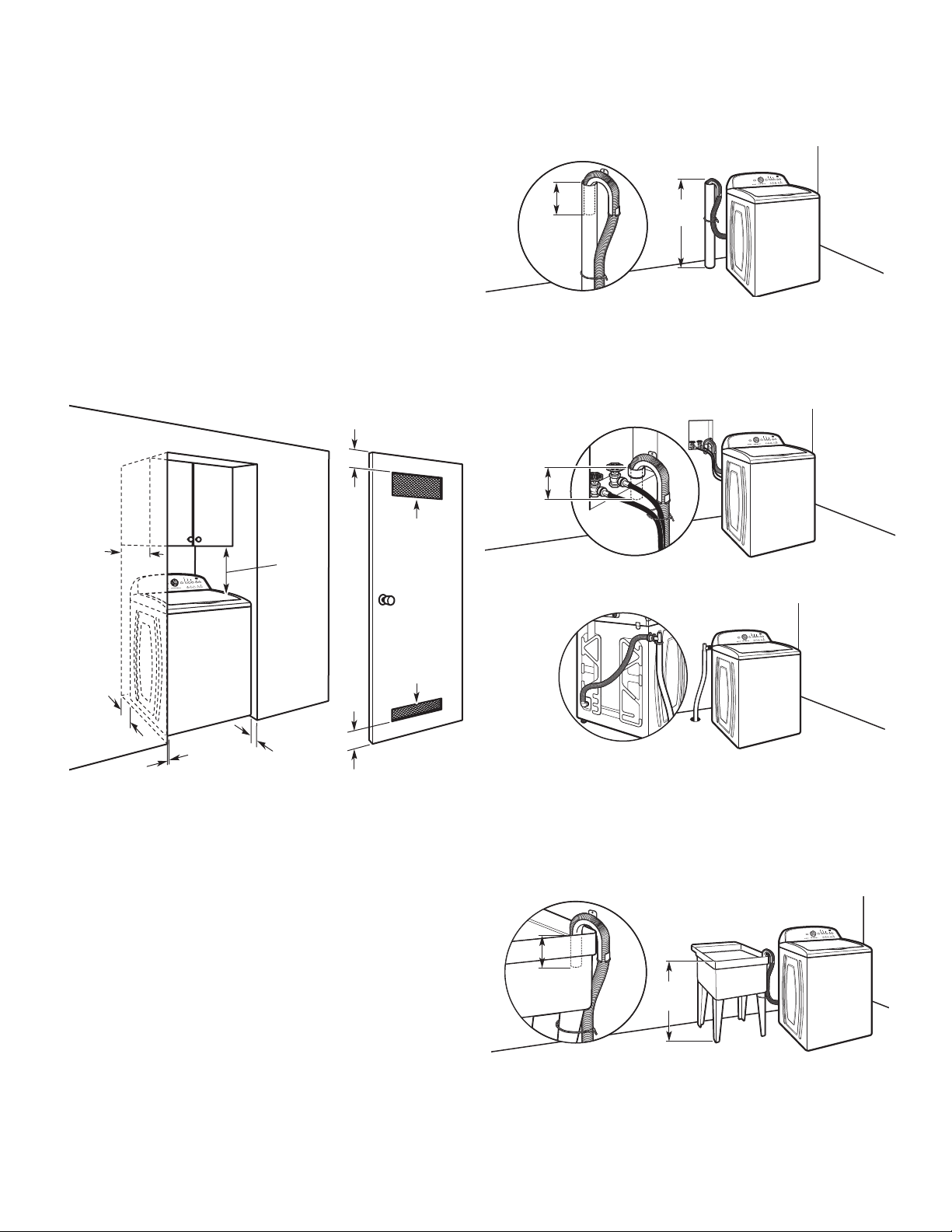
Recessed area or closet installation
(76 mm)
14" max.
(356 mm)
17"
(432 mm)
2
48 in.
(310 cm2)
DRAIN SYSTEM
Drain system can be installed using a floor drain, wall standpipe,
floor standpipe, or laundry tub. Select method you need.
Floor standpipe drain system
39"
4.5"
(114 mm)
Minimum diameter for a standpipe drain: 2" (51 mm). Minimum
carry-away capacity: 17 gal. (64 L) per minute. Top of standpipe
must be at least 39" (990 mm) high; install no higher than
96" (2.44 m) from bottom of washer. If you must install higher
than 96" (2.44 m), you will need a sump pump system.
Wall standpipe drain system
4.5"
(114 mm)
See requirements for floor standpipe drain system.
Floor drain system
(990 mm)
2
24 in.
5"
(126 mm)
1"
(25 mm)
1"
(25 mm)
(76 mm)
(155 cm2)
3"
Dimensions show recommended spacing allowed, except for
closet door ventilation openings which are minimum required.
This washer has been tested for installation with spacing of
0" (0 mm) clearance on the sides. Consider allowing more space
for ease of installation and servicing, and spacing for companion
appliances and clearances for walls, doors, and floor moldings.
Add spacing of 1" (25 mm) on all sides of washer to reduce
noise transfer. If a closet door or louvered door is installed,
top and bottom air openings in door are required.
Floor drain system requires a Siphon Break Kit (Part Number
285834), 2 Connector Kits (Part Number 285835), and an
Extension Drain Hose (Part Number 285863) that may be
purchased separately. Minimum siphon break: 28" (710 mm)
from bottom of washer. (Additional hoses may be needed.)
Laundry tub drain system
39"
(990 mm)
Minimum capacity: 20 gal. (76 L). Top of laundry tub must be at
least 39" (990 mm) above floor; install no higher than 96" (2.44 m)
from bottom of washer.
IMPORTANT: To avoid siphoning, no more than 4.5" (114 mm)
of drain hose should be inside standpipe or below the top of
wash tub. Secure drain hose with cable tie.
3

ELECTRICAL REQUIREMENTS
n
A 120 volt, 60 Hz., AC only, 15- or 20-amp, fused electrical supply
is required. A time-delay fuse or circuit breaker is recommended.
It is recommended that a separate circuit breaker serving only this
appliance be provided.
n
This washer is equipped with a power supply cord having
a 3 prong grounding plug.
n
To minimize possible shock hazard, the cord must be plugged
into a mating, 3 prong, grounding-type outlet, grounded in
accordance with local codes and ordinances. If a mating outlet
is not available, it is the personal responsibility and obligation
of the customer to have the properly grounded outlet installed
by a qualified electrician.
n
If codes permit and a separate ground wire is used, it is
recommended that a qualified electrician determine that
the ground path is adequate.
n
Do not ground to a gas pipe.
n
Check with a qualified electrician if you are not sure the
washer is properly grounded.
n
Do not have a fuse in the neutral or ground circuit.
INSTALLATION INSTRUCTIONS
Before you start: remove shipping materials
It is necessary to remove all shipping materials for proper
operation and to avoid excessive noise from washer.
1. Move washer
48"
(1.2 m)
Move washer to within 4 ft (1.2 m) of its final location; it must
be in a fully upright position.
NOTE: To avoid floor damage, set washer onto cardboard
before moving it and make sure lid is taped shut.
2. Remove shipping base
To avoid damaging floor, place cardboard supports from
shipping carton on floor behind washer. Tip washer back and
place on cardboard supports. Remove shipping base. Set
washer upright.
IMPORTANT: Removing shipping base is necessary for proper
operation. If your washer includes a sound shield, please refer
to the instructions included with the sound shield to install it at
this time.
4
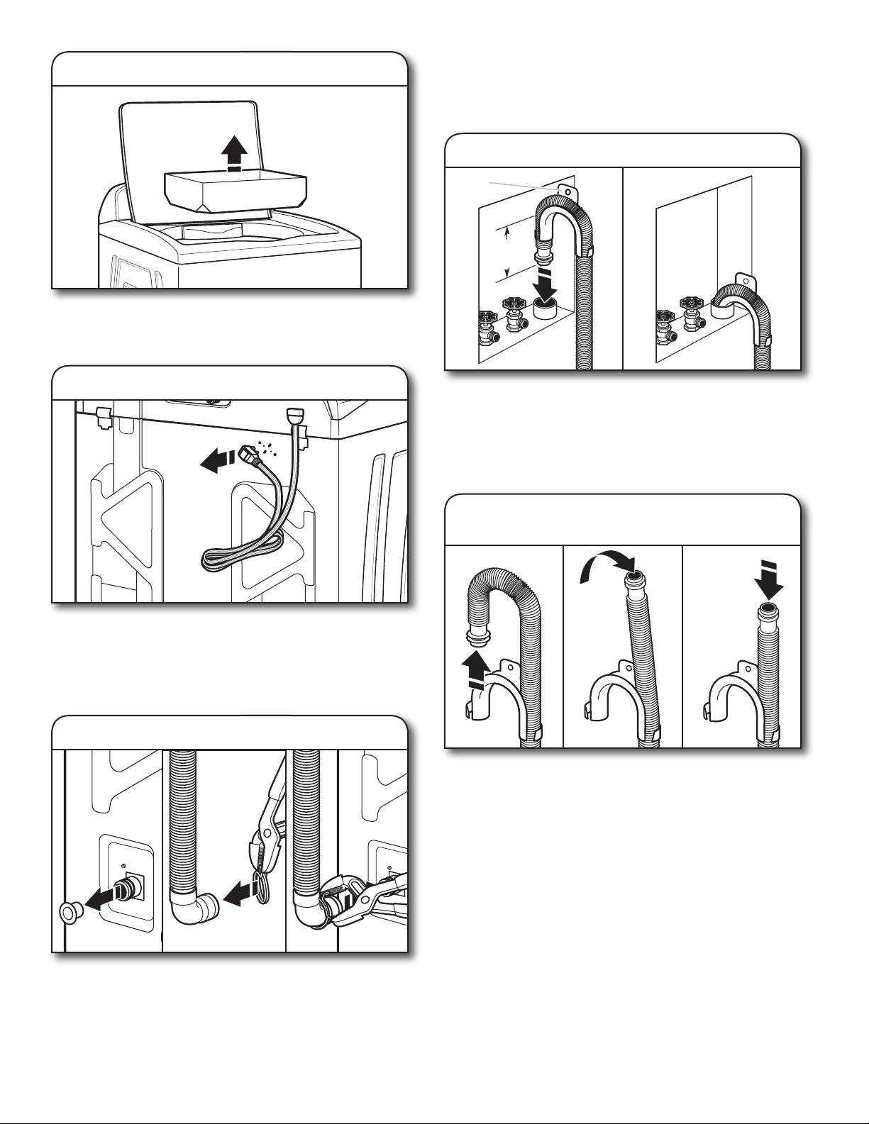
3. Remove packing tray from tub
Remove tape from washer lid, open lid and remove cardboard
packing tray from tub. Be sure to remove all parts from tray.
NOTE: Keep tray in case you need to move washer later.
For a laundry tub or standpipe drain, go to step 6.
For a floor drain, remove the preinstalled drain hose form as
shown in Step 7. You may need additional parts with separate
directions. See “Tools and Parts”.
6. Place drain hose in standpipe
Drain
hose form
4.5"
(114 mm)
4. Free power cord
Firmly grasp power cord plug and pull to free from rear panel.
Gently place power cord over console to allow free access
to back of washer.
CONNECT DRAIN HOSE
5. Attach drain hose to drain port
Place hose into standpipe (shown in picture) or over side of
laundry tub.
IMPORTANT: 4.5" (114 mm) of drain hose should be inside
standpipe; do not force excess hose into standpipe or lay on
bottom of laundry tub. Drain hose form must be used.
7. Remove drain hose form
(floor drain installations only)
For floor drain installations, you will need to remove the drain
hose form from the end of the drain hose. You may need
additional parts with separate directions. See “Tools and Parts”.
Remove the red plastic plug from the black drain port on the
back of the washer.
If clamp is not already in place on elbow end of drain hose,
slide it over end as shown. Squeeze clamp with pliers and
slide black elbow end of drain hose onto black drain port
and secure with clamp.
5
 Loading...