


Model No. WEBE19301
Serial No.
Write the serial number in the space above for reference.
Serial
Number
Decal 


QUESTIONS?
As a manufacturer, we are committed to providing complete customer satisfaction. If you have questions, or if there are missing parts, we will guarantee complete satisfaction through direct assistance from our factory.
TO AVOID UNNECESSARY DELAYS, PLEASE CALL DIRECT TO OUR TOLL-FREE CUSTOMER HOT LINE. The trained technicians on our customer hot line will provide immediate assistance, free of charge to you.
CUSTOMER HOT LINE:
1-800-999-3756
Mon.–Fri., 6 a.m.–6 p.m. MST
 CAUTION
Read all precautions and instructions in this manual before using this equipment. Save this manual for future reference.
®
USER’S MANUAL

 Visit our website at
www.weiderfitness.com
new products, prizes, fitness tips, and much more!

®
Table of Contents
Important Precautions . . . . . . . . . . . . . . . . . . . . . . . . . . . . . . . . . . . . . . . . . . . . . . . . . . . . . . . . . . . . . . . . . . . 3
Before You Begin . . . . . . . . . . . . . . . . . . . . . . . . . . . . . . . . . . . . . . . . . . . . . . . . . . . . . . . . . . . . . . . . . . . . . . 4
Part Identification Chart . . . . . . . . . . . . . . . . . . . . . . . . . . . . . . . . . . . . . . . . . . . . . . . . . . . . . . . . . . . . . . . . . . 5
Assembly . . . . . . . . . . . . . . . . . . . . . . . . . . . . . . . . . . . . . . . . . . . . . . . . . . . . . . . . . . . . . . . . . . . . . . . . . . . . 6
Adjusting the Weight Rack . . . . . . . . . . . . . . . . . . . . . . . . . . . . . . . . . . . . . . . . . . . . . . . . . . . . . . . . . . . . . . 12
Exercise Guidelines . . . . . . . . . . . . . . . . . . . . . . . . . . . . . . . . . . . . . . . . . . . . . . . . . . . . . . . . . . . . . . . . . . . .14
Ordering Replacement Parts . . . . . . . . . . . . . . . . . . . . . . . . . . . . . . . . . . . . . . . . . . . . . . . . . . . . . .Back Cover
Limited Warranty . . . . . . . . . . . . . . . . . . . . . . . . . . . . . . . . . . . . . . . . . . . . . . . . . . . . . . . . . . . . . . . Back Cover
Note: A Part List/Exploded Drawing is attached in the center of this manual. Remove the Part List/Exploded Drawing before beginning assembly.
WEIDER is a registered trademark of ICON Health & Fitness, Inc.
2
Important Precautions
 WARNING: To reduce the risk of serious injury, read the following important precautions before using the weight rack.
1.Read all instructions in this manual before using the weight rack. Use the weight rack only as described in this manual.
2.It is the responsibility of the owner to ensure that all users of the weight rack are adequately informed of all precautions.
3.The weight rack is intended for home use only. Do not use the weight rack in a commercial, rental or institutional setting.
4.Use the weight rack only on a level surface. Cover the floor beneath the weight rack for protection.
5.Inspect and tighten all parts each time you use the weight rack. Replace any worn parts immediately.
6.Keep children under 12 and pets away from the weight rack at all times.
7.Keep hands and feet away from moving parts.
8.Always wear athletic shoes for foot protection while exercising.
9.Always make sure there is an equal amount of weight (not included) on each side of the barbell or the weight carriage.
10.The weight rack is designed to support a maximum of 300 pounds, including the barbell and weights (weights are not included). Do not place more than 300 pounds, including the barbell, on the weight gliders and safety spotters. Do not place more than 150 pounds on the weight carriage.
11.Always set both weight gliders and both safety spotters at the same height.
12.Always secure your weights (not included) with weight clips when they are mounted on the barbell or the weight carriage.
13.Always lower the weight carriage in a controlled manner; never let the weight carriage drop.
14.Always move your bench (not included) out of the way when performing an exercise that does not use the bench.
15.Always remove the lat bar when performing an exercise that does not require the use of the lat bar.
16.If you feel pain or dizziness while exercising, stop immediately and begin cooling down.
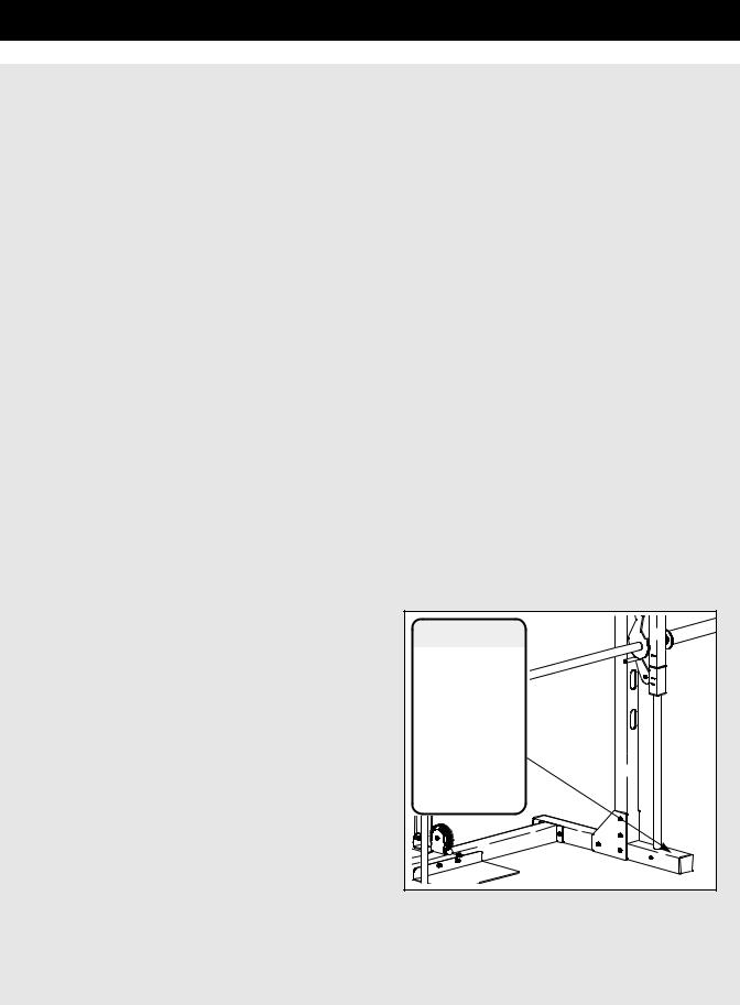
17.The decal shown below has been placed on the weight rack. If the decal is missing or illegible, please call our Customer Service Department toll-free at 1-800-999-3756, Monday through Friday, 6 a.m. until 6 p.m. Mountain Time, to order a free replacement decal. Apply the decal in the location shown.
 WARNING
• Misuse of this product may result in  serious injury.
 • Read user’s manual and follow all war-
  nings and operating instructions prior to use
• Do not allow children on or around machine.
 • Replace label if damaged, illegible, or removed.
 WARNING: Before beginning this or any exercise program, consult your physician. This is especially important for persons over the age of 35 or persons with pre-existing health problems. Read all instructions before using. ICON assumes no responsibility for personal injury or property damage sustained by or through the use of this product.
3
Before You Begin
Thank you for selecting the versatile WEIDER® XT55 PRO weight rack. The XT55 PRO is designed to help you develop every major muscle group of the body.
Whether your goal is a shapely figure, dramatic increase in muscle size and strength, or a healthier cardiovascular system, the XT55 PRO will help you achieve the specific results you want.
For your benefit, read this manual carefully before using the XT55 PRO. If you have additional questions, please call our Customer Service Department toll-free
at 1-800-999-3756, Monday through Friday, 6 a.m. until 6 p.m. Mountain Time (excluding holidays). To help us assist you, please note the product model number and serial number before calling. The model number is WEBE19301. The serial number can be found on a decal attached to the weight rack (see the front cover of this manual).
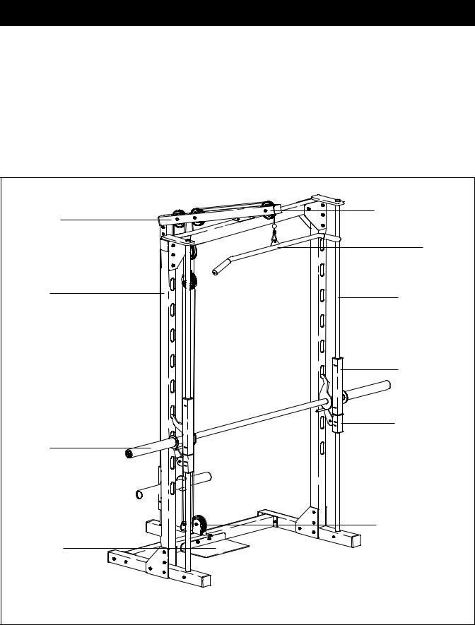
Before reading further, please review the drawing below and familiarize yourself with the parts that are labeled.
Lat Tower
Upright
Right Side
Barbell
Weight Carriage 

Foot Plate
High Pulley Station
Lat Bar
Weight Guide
Left Side
Weight Glider
Safety Spotter
Low Pulley Station
Note: The terms “right side” and “left side” are determined relative to a user standing with his back toward the weight rack; they do not refer to right and left on the drawings in this manual.
4
Part Identification Chart—Model No. WEBE19301 R1200A
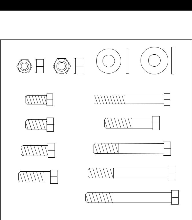
Refer to the drawings below to identify small parts used in assembly. The number in parentheses below each drawing is the key number of the part, from the Part List in the center of this manual. The number following the key number is the quantity needed for assembly. Note: Some small parts may have been pre-attached. If a part is not in the parts bag, check to see if it has been pre-attached.
M8 Nylon |
M10 Nylon |
M10 Small |
M10 Large |
Locknut (54)—1 |
Locknut (11)—40 |
Washer (6)—14 |
Washer (58)—6 |
M8 x 20mm Screw (50)—2 |
M8 x 70mm Bolt (30)—1 |
||
M10 x 20mm Bolt (26)—2 |
M10 x 45mm Bolt (40)—3 |
||
|
|
||
M10 x 25mm Bolt (43)—4 |
M10 x 65mm Bolt (56)—7 |
||
|
|
||
M10 x 30mm Bolt (38)—2 |
M10 x 75mm Bolt (39)—2 |
||
|
|
||
|
|
M10 x 80mm Bolt (41)—24 |
|
|
|
5 |
|
Assembly
Before beginning assembly, carefully read the following information and instructions:
Make Things Easier for Yourself!
This manual is designed to ensure that the weight rack can be assembled successfully by anyone. By setting aside plenty of time, and by deciding to make the task enjoyable, assembly will go smoothly.
•Assembly requires two people.
•Place all parts in a cleared area and remove the packing materials. Do not dispose of the packing materials until assembly is completed.
•Tighten all parts as you assemble them, unless instructed to do otherwise.
•As you assemble the weight rack, make sure all parts are oriented as shown in the drawings.
•For help identifying small parts, use the PART IDENTIFICATION CHART on page 5. Note:
Some small parts may be pre-assembled.
Assembly requires the following tools (not included):
• Two adjustable wrenches
• One rubber mallet
• One standard screwdriver
• One phillips screwdriver
•Lubricant, such as grease or petroleum jelly, and soapy water.
Assembly will be more convenient if you have a socket set, a set of open-end or closed-end wrenches, or a set of ratchet wrenches.
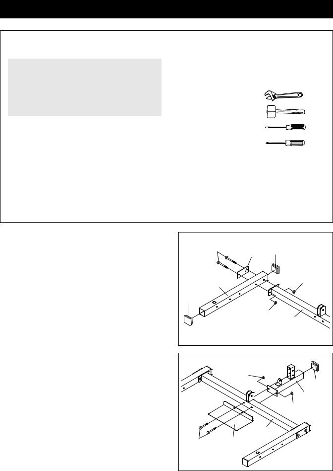
1.Before beginning, make sure you understand the information in the box above. Note: Some parts described in the assembly steps may be pre-assembled.
Press a 60mm Square Inner Cap (55) into each end of a Base (7). Attach the Base to the indicated end of the Base Crossbar (20) using a Support Plate (57), two M10 x 80mm Bolts (41), and two M10 Nylon Locknuts (11). Do not tighten the Nylon
Locknuts yet.
Attach the other Base (7) to the opposite side of the Base Crossbar (20) in the same manner.
2.Press a 60mm Square Inner Cap (55) into the end of the Rear Base (3). Attach the Rear Base and the Foot Plate (4) to the Base Crossbar (20) using two M10 x 80mm Bolts (41) and two M10 Nylon Locknuts (11). Do not tighten the Nylon Locknuts yet.
1 |
|
|
|
|
41 |
57 |
55 |
|
|
||
|
|
|
|
|
7 |
|
11 |
|
|
|
|
55 |
|
|
|
|
|
|
11 |
|
|
|
20 |
2 |
|
|
|
|
|
11 |
55 |
|
|
|
|
|
|
|
3 |
|
|
|
11 |
|
|
|
20 |
41 |
|
4 |
|
6
 Loading...